WIRELESS MADE SIMPLE Product Overview Guide Sheets/Linx Technologies PDFs/linxovrvw.pdfWIRELESS MADE...
48
Product Overview Guide Quarter 1, 2004 WIRELESS MADE SIMPLE Product Overview Guide Quarter 1, 2004 RF MODULES ANTENNAS CONNECTORS EVALUATION KITS TESTING SUPPORT RF MODULES ANTENNAS CONNECTORS EVALUATION KITS TESTING SUPPORT
Transcript of WIRELESS MADE SIMPLE Product Overview Guide Sheets/Linx Technologies PDFs/linxovrvw.pdfWIRELESS MADE...
Product Overview GuideQuarter 1, 2004
WIRELESS MADE SIMPLE
Product Overview GuideQuarter 1, 2004
RF MODULESANTENNASCONNECTORSEVALUATION KITSTESTINGSUPPORT
RF MODULESANTENNASCONNECTORSEVALUATION KITSTESTINGSUPPORT

Page 2 Page 3
About LinxFrom all of us here at Linx Technologies, thank you for your interest inlearning more about our rapidly growing company. The following sectionwill provide a brief insight into our history, vision and future.
Our HistoryFounded in 1994, Linx Technologies is a privately held growth-modecorporation consisting of three divisions. The first and primary division,Linx Technologies, shares the corporate name and specializes in low-costwireless modules and OEM RF product solutions. The second division,Antenna Factor, specializes in cost-effective standard and customantennas for consumer and industrial wireless products. Finally, a thirddivision, Connector City, provides world-class standard and customconnectors and cable assemblies for high-volume OEM applications.
Our VisionRadio Frequency (RF) is a complex science requiring a unique grasp ofboth advanced technical issues and complex legal requirements; thus,adding wireless capabilities to a product has traditionally been a costlyand time-consuming proposition. This has limited the widespread use ofRF and prevented many potentially useful products from reachingproduction.
Here at Linx, we believe that every engineer, regardless of training andexperience, should have the option of using RF technology. That’s why“Wireless Made Simple” is more than just a motto.... It’s our commitment.A commitment to offering the highest quality RF products designed toprovide a simple and cost-effective path to making any product wireless.
Through its three divisions, Linx Technologies, Inc., is positioned to takeadvantage of the exploding wireless market it helped to create. We believethat our vision for enabling engineers of all skill levels in diverseindustries to harness the power of RF will allow Linx continuedrecognition as a leader in RF solutions.
Welcome to the Products & Services of
RF MODULES 1
EVALUATION SYSTEMS 2
RF AMPLIFIERS 3
INTERFACE MODULES 4
PRECERTIFIED OEM PRODUCTS 5
ANTENNAS 6
CONNECTORS 7
ADDITIONAL SERVICES 8
APPLICATIONS LITERATURE 9
Table of Contents
WIRELESS MADE SIMPLE
Phone: (541) 471-6256FAX: (541) 471-6251http://[email protected]
Page 4 Page 5
Part Number
Series
Frequen
cy (M
Hz)
Vcc (V
)
Icc (m
A) Typ
.
Analog Ran
ge
Max. D
ata Rate
(bps)Pac
kage
Page
LC
KH
RF MODULES 1
RM
HP
ES
KH
ES
HP
RM
LC
SC
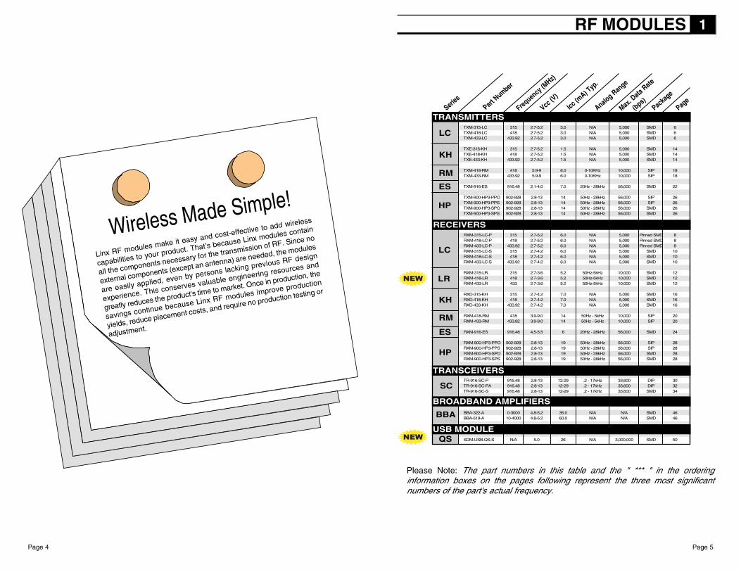
Please Note: The part numbers in this table and the " *** " in the orderinginformation boxes on the pages following represent the three most significantnumbers of the part's actual frequency.
Wireless Made Simple!
Linx RF modules make it easy and cost-effective to add wireless
capabilities to your product. That’s because Linx modules contain
all the components necessary for the transmission of RF. Since no
external components (except an antenna) are needed, the modules
are easily applied, even by persons lacking previous RF design
experience. This conserves valuable engineering resources and
greatly reduces the product's time to market. Once in production, the
savings continue because Linx RF modules improve production
yields, reduce placement costs, and require no production testing or
adjustment.
BBA
TRANSMITTERS
RECEIVERS
TRANSCEIVERS
BROADBAND AMPLIFIERS
LRNEW
NEW QSUSB MODULE
TXM-315-LC 315 2.7-5.2 3.0 N/A 5,000 SMD 6TXM-418-LC 418 2.7-5.2 3.0 N/A 5,000 SMD 6TXM-433-LC 433.92 2.7-5.2 3.0 N/A 5,000 SMD 6
TXE-315-KH 315 2.7-5.2 1.5 N/A 5,000 SMD 14TXE-418-KH 418 2.7-5.2 1.5 N/A 5,000 SMD 14TXE-433-KH 433.92 2.7-5.2 1.5 N/A 5,000 SMD 14
TXM-418-RM 418 5.9-9 6.0 0-10KHz 10,000 SIP 18TXM-433-RM 433.92 5.9-9 6.0 0-10KHz 10,000 SIP 18
TXM-916-ES 916.48 2.1-4.0 7.0 20Hz - 28kHz 56,000 SMD 22
TXM-900-HP3-PPO 902-928 2.8-13 14 50Hz - 28kHz 56,000 SIP 26TXM-900-HP3-PPS 902-928 2.8-13 14 50Hz - 28kHz 56,000 SIP 26TXM-900-HP3-SPO 902-928 2.8-13 14 50Hz - 28kHz 56,000 SMD 26TXM-900-HP3-SPS 902-928 2.8-13 14 50Hz - 28kHz 56,000 SMD 26
RXM-315-LC-P 315 2.7-5.2 6.0 N/A 5,000 Pinned SMD 8RXM-418-LC-P 418 2.7-5.2 6.0 N/A 5,000 Pinned SMD 8RXM-433-LC-P 433.92 2.7-5.2 6.0 N/A 5,000 Pinned SMD 8RXM-315-LC-S 315 2.7-4.2 6.0 N/A 5,000 SMD 10RXM-418-LC-S 418 2.7-4.2 6.0 N/A 5,000 SMD 10RXM-433-LC-S 433.92 2.7-4.2 6.0 N/A 5,000 SMD 10
RXM-315-LR 315 2.7-3.6 5.2 50Hz-5kHz 10,000 SMD 12RXM-418-LR 418 2.7-3.6 5.2 50Hz-5kHz 10,000 SMD 12RXM-433-LR 433 2.7-3.6 5.2 50Hz-5kHz 10,000 SMD 12
RXD-315-KH 315 2.7-4.2 7.0 N/A 5,000 SMD 16RXD-418-KH 418 2.7-4.2 7.0 N/A 5,000 SMD 16RXD-433-KH 433.92 2.7-4.2 7.0 N/A 5,000 SMD 16
RXM-418-RM 418 3.9-9.0 14 50Hz - 5kHz 10,000 SIP 20RXM-433-RM 433.92 3.9-9.0 14 50Hz - 5kHz 10,000 SIP 20
RXM-916-ES 916.48 4.5-5.5 6 20Hz - 28kHz 56,000 SMD 24
RXM-900-HP3-PPO 902-928 2.8-13 19 50Hz - 28kHz 56,000 SIP 28RXM-900-HP3-PPS 902-928 2.8-13 19 50Hz - 28kHz 56,000 SIP 28RXM-900-HP3-SPO 902-928 2.8-13 19 50Hz - 28kHz 56,000 SMD 28RXM-900-HP3-SPS 902-928 2.8-13 19 50Hz - 28kHz 56,000 SMD 28
TR-916-SC-P 916.48 2.8-13 12-29 .2 - 17kHz 33,600 DIP 30TR-916-SC-PA 916.48 2.8-13 12-29 .2 - 17kHz 33,600 DIP 32TR-916-SC-S 916.48 2.8-13 12-29 .2 - 17kHz 33,600 SMD 34
BBA-322-A 0-3000 4.8-5.2 35.0 N/A N/A SMD 46BBA-519-A 10-4000 4.8-5.2 60.0 N/A N/A SMD 46
SDM-USB-QS-S N/A 5.0 26 N/A 3,000,000 SMD 50

Page 6 Page 7
WIRELESS MADE SIMPLE
Remote Control Keyless EntryGarage / Gate OpenersLighting ControlMedical Monitoring / Call SystemsRemote Industrial MonitoringPeriodic Data TransferHome / Industrial AutomationFire / Security AlarmsRemote Status / Position SensingLong-Range RFIDWire Elimination
APPLICATIONS INCLUDE
Low Cost
No External Components Required
Ultra-Low Power Consumption
Compact Surface-Mount Package
Stable SAW-Based Architecture
Supports Data Rates to 5,000bps
Wide Supply Range (2.7-5.2VDC)
Direct Serial Interface
Low Harmonics
No Production Tuning
The LC Series is ideally suited for volumeuse in OEM applications such as remotecontrol, security, identification, andperiodic data transfer. Packaged in acompact SMD package, the LCtransmitter utilizes a highly optimizedSAW architecture to achieve anunmatched blend of performance, size,efficiency and cost. When paired with amatching LC or LR Series receiver, ahighly reliable wireless link is formed,capable of transferring serial data atdistances in excess of 300 feet. Noexternal RF components, except anantenna, are required, making designintegration straightforward, even forengineers lacking previous RFexperience.
0.360"
0.500"
0.150" Max
TOP VIEW
SIDE VIEW
PHYSICAL DIMENSIONS
DESCRIPTION
FEATURES
Performance Data - TXM-***-LC
Test/Basic Application Circuit
About These MeasurementsThe performance parameters listedbelow are based on moduleoperation at 25°C from a 3.3VDCsupply unless otherwise noted. Thefigure at the right illustrates theconnections necessary for testingand operation. It is recommendedthat all ground pins be connected tothe groundplane.
1. Current draw with data pin held continuously high2. Current draw with data pin low3. RF out connected to 50Ω load4. LADJ (Pin 4) through 430Ω resistor
NOTES:
PART # DESCRIPTIONTXM-***-LC LC Transmitter EVAL-***-LC-P LC Basic Evaluation SystemMDEV-***-LC-P LC Master Development System*** = Frequency 315, 418, 433.92 MHzLC TX modules are supplied in tubes of 50 pcs.
ORDERING INFORMATION
PINOUTS
LC SERIES TRANSMITTER MODULE
TOP VIEW
PPaarraammeetteerr DDeessiiggnnaattiioonn MMiinn.. TTyyppiiccaall MMaaxx.. UUnniittss NNootteess
PPOOWWEERR SSUUPPPPLLYYSupply Voltage VCC 2.7 – 5.2 VDC –Supply Current ICC – 3.0 6.0 mA 1,4Sleep Current ISLP – – 1.5 µA 2TTRRAANNSSMMIITT SSEECCTTIIOONNTransmit Frequency FC
TXM-315-LC 314.925 315.0 315.075 MHz –TXM-418-LC 417.925 418 418.075 MHz –TXM-433-LC 433.845 433.92 433.995 MHz –
Center Frequency Accuracy – -75 – +75 kHz –Output Power PO -4 0 +4 dBm 3Harmonic Emissions PH – – -40 dBc 3Data Bandwidth – 100 – 5,000 bps –Data input
Logic low VIL 0 – 0.4 VDC –Logic high VIH 2.5 – VCC VDC –
AANNTTEENNNNAA PPOORRTTRF output impedance RIN – 50 – Ohms –TTIIMMIINNGGTransmitter Turn-on Time TOSU – – 80 µS 3Transmitter Turn-off Time TORD – – 100 nSecEENNVVIIRROONNMMEENNTTAALLOperational Temperature – -30 – +70 °C –
RF
MO
DU
LE
S1

Page 9Page 8
WIRELESS MADE SIMPLE
Low Cost No External Components RequiredLow Power ConsumptionCompact “L” Leg Surface-Mount PackageStable SAW-Based ArchitectureOutstanding Sensitivity
Supports Data Rates to 5,000bps
Wide Supply Range (2.7-5.2VDC)
Qualified Data Output
Direct Serial Interface
No Production Tuning
FEATURES
The LC Series is ideally suited for volumeuse in OEM applications such as remotecontrol, security, identification, and periodicdata transfer. Available in 2 styles ofcompact SMD packages, the LC receiverutilizes a highly optimized SAW architectureto achieve an unmatched blend ofperformance, size, efficiency and cost.When paired with a matching LC or LRSeries transmitter, a highly reliable wirelesslink is formed, capable of transferring serialdata at distances in excess of 300 feet. Noexternal RF components, except anantenna, are required, making designintegration straightforward, even forengineers lacking previous RF experience.
0.890"
0.220"
0.040"
0.592"
0.835"
PINOUTS
PHYSICAL DIMENSIONS
About These MeasurementsThe performance parameters listedbelow are based on moduleoperation at 25°C from a 3.3VDCsupply unless otherwise noted. Thefigure at the right illustrates theconnections necessary for testingand operation. It is recommendedall ground pins be connected to thegroundplane.
1. VCC applied to Pin 10. Pin 10 is connected to VCC for VCC=2.7 - 4.2V. Pin 6 is not connected2. VCC applied to Pin 6. Pin 6 is connected to VCC for VCC=4 - 5.2V. Pin 10 is not connected3. For BER of 10-5 @ 4800 baud. Sensitivity is affected by the antenna’s SWR4. Time to valid data output
Notes:
Test / Basic Application Circuit
Remote Control
Keyless Entry
Garage / Gate Openers
Lighting Control
Medical Monitoring / Call Systems
Remote Industrial Monitoring
Periodic Data Transfer
Home / Industrial Automation
Fire / Security Alarms
Remote Status / Position Sensing
Long-Range RFID
Wire Elimination
APPLICATIONS INCLUDE
P-STYLE (PINNED SMD VERSION)
PART # DESCRIPTIONRXM-***-LC-P LC Receiver (Pinned SMD)EVAL-***-LC-P LC Basic Evaluation SystemMDEV-***-LC-P LC Master Development System*** = Frequency 315, 418, 433.92 MHzLC-P RX modules are supplied in tubes of 40 pcs.
ORDERING INFORMATION
LC SERIESRECEIVER MODULE
TTHHIISS SSTTYYLLEE NNOOTT RREECCOOMMMMEENNDDEEDD FFOORR NNEEWW DDEESSIIGGNNSS
DESCRIPTION
109876
VCC 2.7-4.2NCGNDPDN/NCVCC 4-5.2
ANTNC
GNDNC
DATA
12345
TOP VIEW
PPaarraammeetteerr DDeessiiggnnaattiioonn MMiinn.. TTyyppiiccaall MMaaxx.. UUnniittss NNootteess
PPOOWWEERR SSUUPPPPLLYYSupply Voltage Pin 10 VCC 2.7 – 4.2 VDC –Supply Voltage Pin 6 VCC 4.0 – 5.2 VDC –Supply Current ICC
VCC = 3V 4.0 6.0 8.0 mA 1VCC = 5V 4.0 6.0 8.0 mA 2
Sleep Current ISLPVCC = 3V – – 300 µA 1VCC = 5V – – 370 µA 2
RREECCEEIIVVEE SSEECCTTIIOONNReceive Frequency FC
RXM-315-LC-P 314.925 315.0 315.075 MHz –RXM-418-LC-P 417.925 418 418.075 MHz –RXM-433-LC-P 433.845 433.92 433.995 MHz –
Center Frequency Accuracy – -75 – +75 kHz –Noise BW – 280 – kHz –Sensitivity @10-5 BER -92 -102 -106 dBm 3Data Bandwidth – 100 – 5,000 bps –Data Output
Logic low VOL 0 – 0.2 VDC –Logic high VOH VCC-0.3 – VCC VDC –
AANNTTEENNNNAA PPOORRTTRF input impedance RIN – 50 – Ohms –TTIIMMIINNGGReceiver Turn-on Time TOSU 5 7 10 mSec 4EENNVVIIRROONNMMEENNTTAALLOperational Temperature – -30 – +70 °C –
Performance Data - RXM-***-LC-P
RF
MO
DU
LE
S1

Page 11
About These MeasurementsThe performance parameters listedbelow are based on module operation at25°C from a 3VDC supply unlessotherwise noted. The figure at the rightillustrates the connections necessary fortesting and operation. It is recommendedall ground pads be connected to thegroundplane.
NC
3VDC
5VDC
200Ω NCNCGNDVCCPDNNCDATA
16 1514131211109
ANTGND
NCNCNCNCNCNC
123
54
678
ExternalResistor
Notes:1. For BER of 10-5 @ 4800 baud. Sensitivity is affected by the antenna’s SWR.2. Time to valid data output3. *CRITICAL* In order to operate the device over this range it is necessary for a 200Ω resistor to be placed
in-line with VCC.4. When operating from a 5-volt source it is important to consider that the output will swing to less than 5 volts
as a result of the required dropping resistor. Please verify that the minimum voltage will meet the highthreshold requirement of the device to which data is being sent.
Test / Basic Application Circuit (Top View)
PPaarraammeetteerr DDeessiiggnnaattiioonn MMiinn.. TTyyppiiccaall MMaaxx.. UUnniittss NNootteess
PPOOWWEERR SSUUPPPPLLYYSupply Voltage VCC 2.7 – 4.2 VDC –
with dropping resistor 4.7 – 5.2 VDC 3Supply Current ICC
VCC = 3V 4.0 6.0 8.0 mA –Sleep Current ISLP
VCC = 3V – 700 930 µA –RREECCEEIIVVEE SSEECCTTIIOONNReceive Frequency FC
RXM-315-LC-P 314.925 315.0 315.075 MHz –RXM-418-LC-P 417.925 418 418.075 MHz –RXM-433-LC-P 433.845 433.92 433.995 MHz –
Center Frequency Accuracy – -75 – +75 kHz –Noise BW – 280 – kHz –Sensitivity @10-5 BER -92 -102 -106 dBm 1Data Bandwidth – 100 – 5,000 bps –Data Output
Logic low VOL 0 – 0.2 VDC –Logic high VOH VCC-0.3 – VCC VDC 4
AANNTTEENNNNAA PPOORRTTRF input impedance RIN – 50 – Ohms –TTIIMMIINNGGReceiver Turn-on Time TOSU 5 7 10 mSec 2EENNVVIIRROONNMMEENNTTAALLOperational Temperature – -30 – +70 °C –
Page 10
WIRELESS MADE SIMPLE
Remote Control / Keyless Entry
Garage / Gate Openers
Lighting Control
Medical Monitoring / Call Systems
Remote Industrial Monitoring
Periodic Data Transfer
Home / Industrial Automation
Fire / Security Alarms
Wire Elimination
Long-Range RFID
APPLICATIONS INCLUDE
Low Cost No External Components RequiredLow Power ConsumptionCompact True Surface-Mount PackageStable SAW-Based ArchitectureOutstanding Sensitivity
Supports Data Rates to 5,000bpsDirect Serial InterfaceNo Production TuningWide Supply Range (2.7 - 5.2VDC)
FEATURES
The LC Series is ideally suited for volumeuse in OEM applications such as remotecontrol, security, identification, andperiodic data transfer. Available in 2styles of compact SMD packages, the LCreceiver utilizes a highly optimized SAWarchitecture to achieve an unmatchedblend of performance, size, efficiencyand cost. When paired with a matchingLC or LR Series transmitter, a highlyreliable wireless link is formed, capableof transferring serial data at distances inexcess of 300 feet. No external RFcomponents, except an antenna, arerequired, making design integrationstraightforward.
DESCRIPTION
0.812"
0.630"
0.14"
PINOUTS
PHYSICAL DIMENSIONS
ULTRA-COMPACT S-STYLE (SMD VERSION)
PART # DESCRIPTIONRXM-***-LC-S LC Receiver (SMD)EVAL-***-LC-S LC-S Basic Evaluation System*** = Frequency 315, 418, 433.92 MHzLC-S RX modules are supplied in tubes of 25 pcs.
ORDERING INFORMATION
LC SERIES RECEIVER MODULE
TOP VIEW
Performance Data - RXM-***-LC-S
RF
MO
DU
LE
S1

PRELIMINARY
DESCRIPTIONThe LR Receiver is ideal for the wirelesstransfer of serial data, control, or commandinformation in the favorable 260-470MHz band.The receiver’s advanced synthesized superhetarchitecture achieves an outstanding typicalsensitivity of -112dBm, which provides a 5-10times improvement in range over previoussolutions. When paired with a Linx LC or LRtransmitter, a reliable wireless link is formed, capable of transferring data at ratesof up to 10,000bps at distances in excess of 3,000 feet. Applications operating atshort distances, or lower data rates will also benefit from increased link reliabilityand superior noise immunity. Housed in a tiny reflow compatible SMD package,the LR Receiver module is footprint compatible with the popular LC-S Receiver,allowing existing users an instant path to improved range and lower cost. Noexternal components are required (except an antenna), allowing for easyintegration, even by engineers without previous RF experience.
Page 12Page 12
LR SERIES RECEIVER MODULE
Remote Control Keyless EntryGarage / Gate OpenersLighting ControlMedical Monitoring / Call SystemsRemote Industrial MonitoringPeriodic Data TransferHome / Industrial AutomationFire / Security AlarmsRemote Status / Position SensingLong-Range RFIDWire Elimination
APPLICATIONS INCLUDE
Long RangeLow-Cost PLL Synthesized ArchitectureDirect Serial InterfaceData Rates to 10,000 bpsQualified Data Output No External Components Needed
Low Power Consumption
Wide Supply Range (2.7 - 5.2VDC)
Compact Surface-mount Package
Wide Temperature Range
RSSI and Power-Down Functions
No Production Tuning
FEATURES
0.125 in.
0.812 in.
0.630 in.
PART # DESCRIPTIONEVAL-***-LR Basic Evaluation KitMDEV-***-LR Master Development KitTXM-315-LR Transmitter 315 MHzTXM-418-LR Transmitter 418 MHz TXM-433-LR Transmitter 433 MHzRXM-315-LR Receiver 315 MHzRXM-418-LR Receiver 418 MHzRXM-433-LR Receiver 433 MHz*** Insert FrequencyLR-S RX modules are supplied in tubes of 25 pcs.
ORDERING INFORMATION
Page 13
WIRELESS MADE SIMPLE
Page 13
Performance Data - RXM-***-LR-S
PRELIMINARY
1. The LR can utilize a 4.3 - 5.2VDC supply provided a 330 ohm resistor is placed in serieswith VCC.
2. Matched to 50 ohms.3. When operating from a 5 volt source it is important to consider that the output will swing
to well less than 5 volts as a result of the required dropping resistor. Please verify that theminimum voltage will meet the high threshold requirement of the device to which data isbeing sent.
4. For BER of 10-5 at 1200bps.
5. Characterized, but not tested.6. Time to valid data output.
Notes:
PPaarraammeetteerr DDeessiiggnnaattiioonn MMiinn.. TTyyppiiccaall MMaaxx.. UUnniittss NNootteess
PPOOWWEERR SSUUPPPPLLYYOperating Voltage VCC 2.7 3.0 3.6 VDC –
With Dropping Resistor 4.3 5.0 5.2 VDC 1,5Supply Current ICC 4.0 5.2 7.0 mA –Power-down Current IPDN 20 28 35 µA 5RREECCEEIIVVEERR SSEECCTTIIOONNReceive Frequency Range FC
RXM-315-LR – 315 – MHz –
RXM-418-LR – 418 – MHz –
RXM-433-LR – 433.92 – MHz –
Center Frequency Accuracy – -50 – +50 kHz –
LO Feedthrough – – -80 – dBm 2,5
IF – – 10.7 – MHz 5
Noise Bandwidth N3DB – 280 – kHz –
Data Rate – 100 – 10,000 bps –
Data OutputLogic Low – – 0.0 – VDC 3Logic High – – 3.0 – VDC 3
Receiver Sensitivity – -106 -112 -118 dBm 2,4
RSSI / Analog:Dynamic Range – – 80 – dB 5
Analog Bandwidth – 50 – 5000 Hz 5
Gain – – 16 – mV/dB 5
Voltage/No Carrier – – 1.5 – V 5
AANNTTEENNNNAA PPOORRTTRF Input Impedance RIN – 50 – Ω 5
TTIIMMIINNGGReceiver Turn-On Time:
Via VCC– 3.0 7 10.0 mSec 5, 6
Via PDN – 0.04 0.25 0.5 mSec 5, 6
Max Time Between Transitions – – 10 – mSec 5EENNVVIIRROONNMMEENNTTAALLOperating Temperature Range – -40 – +70 °C 5
PHYSICAL DIMENSIONS
RF
MO
DU
LE
S1

Page 15Page 14
WIRELESS MADE SIMPLE
Performance Data - TXE-***-KH
GND/LVLD0D1GNDVCCTED2D3D4D5D6D7
ANTGND
A9A8A7A6A5A4A3A2A1A0
12
3456
78
91011
2423
2221201918171615141312
3VDC
VCC
Test Circuit (Top View)
About These MeasurementsThe performance parameters listedbelow are based on moduleoperation at 25°C from a 3VDCsupply unless otherwise noted. Thefigure at the right illustrates theconnections necessary for testingand operation. It is recommendedthat all ground pins be connected tothe groundplane.
1. Current draw with 50% mark / space ratio2. Current draw in standby3. RF out connected to 50Ω load
Notes:
PPaarraammeetteerr DDeessiiggnnaattiioonn MMiinn.. TTyyppiiccaall MMaaxx.. UUnniittss NNootteess
PPOOWWEERR SSUUPPPPLLYYSupply Voltage VCC 2.7 – 5.2 VDC –Supply Current ICC – 1.5 – mA 1Sleep Current ISLP – 1.0 – µA 2TTRRAANNSSMMIITT SSEECCTTIIOONNTransmit Frequency FC
TXM-315-LC 314.925 315.0 315.075 MHz –TXM-418-LC 417.925 418 418.075 MHz –TXM-433-LC 433.845 433.92 433.995 MHz –
Center Frequency Accuracy – -75 – +75 kHz –Output Power PO -4 0 +4 dBm 3Harmonic Emissions PH – – -40 dBc 3Data Bandwidth – 100 – 5,000 bps –Data input
Logic low VIL 0 – 0.3 VDC –Logic high VIH 0.7xVcc – VCC VDC –
AANNTTEENNNNAA PPOORRTTRF output impedance RIN – 50 – Ohms –EENNCCOODDEERRTX Data Length – – 26bits 3x – – –Average Data Duty Cycle – – 50% – – –Encoder Oscillator FENC – 70 – kHz –EENNVVIIRROONNMMEENNTTAALLOperational Temperature – -30 – +70 °C –
RF TRANSMITTER WITH INTEGRATED ENCODER
The KH Series is ideally suited for volumeuse in OEM applications such as remotecontrol / command and keyless entry. Itcombines a highly optimized RFtransmitter with an on-board encoder.When paired with a compatible receiver /decoder module, a highly reliable wirelesslink is formed, capable of transferring thestatus of 1 to 8 parallel inputs along with310 addresses for distances in excess of300 feet. Packaged in a compact SMDpackage, the KH module utilizes a highlyoptimized SAW architecture to achieve anunmatched blend of performance, size,and cost. No external RF components,except an antenna, are required, makingdesign integration straightforward.
Remote Control / CommandKeyless EntryGarage / Gate OpenersLighting ControlCall SystemsHome / Industrial AutomationFire / Security AlarmsRemote Status MonitoringWire Elimination
APPLICATIONS INCLUDE
Low Cost
On-Board Encoder
8 Parallel Binary Outputs Allow DirectConnection of Peripherals
310 Addresses for Security and Uniqueness
No External Components Required
Ultra-Low Power Consumption
Compact Surface-Mount Package
Stable SAW-Based Architecture
No Production Tuning
FEATURES
GND/LVLD0D1GNDVCCTED2D3
2423222120191817
ANTGND
A9A8A7A6A5A4
D4 A3D5 A2D6 A1D7 A0
12345678
169151014111312
TOP VIEW
1.220 in.31.3 mm
0.18 in.
.630 in.16.2 mm
4.6 mm
LOT 2000
RF TRANSMITTER/ENCODERTXE-418-KH
PINOUTS
PHYSICAL DIMENSIONS
DESCRIPTION
PART # DESCRIPTIONTXE-***-KH KH TX / EncoderEVAL-***-KH KH Evaluation System*** = Frequency 315, 418, 433.92 MHzKH TX modules are supplied in tubes of 20 pcs.
ORDERING INFORMATION
KH SERIES TRANSMITTER MODULE
RF
MO
DU
LE
S1

Page 17Page 16
WIRELESS MADE SIMPLE
Performance Data - RXD-***-KH
About These MeasurementsThe performance parameters listed beloware based on module operation at 25°Cfrom a 3VDC supply unless otherwisenoted. The figure at the right illustrates theconnections necessary for testing andoperation. It is recommended all groundpins be connected to the groundplane. Thepins marked NC have no physicalconnection and are designed only to addsupport.
Test / Basic Application Circuit(Top View)
NCD0D1GNDVCCPDND2D3D4DATAVTD5
ANTGND
NCNCA9A8A7A6A5A4A3A2
D6 A1D7 A0
12345
6789
1011
2827
262524232221201918171615
121314
3VDC
5VDC
200ΩExternalResistor
1. Sensitivity is affected by the antenna’s SWR.2. Potential rate of data recovered at RX data (Pin 10). Decoder rate is internally fixed3. Maximum drive capability of data outputs4. *CRITICAL* In order to operate the device over this range it is necessary for a 200Ω resistor
to be placed in-line with VCC5. When operating from a 5-volt source it is important to consider that the output will swing to well
less than 5 volts as a result of the required dropping resistor. Please verify that the minimumvoltage will meet the high threshold requirement of the device to which data is being sent
Notes:
PPaarraammeetteerr DDeessiiggnnaattiioonn MMiinn.. TTyyppiiccaall MMaaxx.. UUnniittss NNootteess
PPOOWWEERR SSUUPPPPLLYYSupply Voltage VCC 2.7 – 4.2 VDC –
with dropping resistor 4.7 – 5.2 VDC 4Supply Current ICC
VCC = 3V 5.0 7.0 8.0 mA –Sleep Current ISLP
VCC = 3V – 700 950 µA –RREECCEEIIVVEE SSEECCTTIIOONNReceive Frequency FC
RXM-315-LC-P 314.925 315.0 315.075 MHz –RXM-418-LC-P 417.925 418 418.075 MHz –RXM-433-LC-P 433.845 433.92 433.995 MHz –
Center Frequency Accuracy – -75 – +75 kHz –Noise BW – 280 – kHz –Sensitivity @10-5 BER -92 -102 -106 dBm 1Data Bandwidth – 100 – 5,000 bps 2Data Output
Logic low VOL 0 – 0.3 VDC 5Logic high VOH VCC-0.3 – VCC VDC 5
AANNTTEENNNNAA PPOORRTTRF input impedance RIN – 50 – Ohms –DDEECCOODDEERRTX Data Length – – 26bits 3x – – –Average Data Duty Cycle – – 50% – – –Decoder Oscillator FENC – 70 – kHz –Decoder Drive Current 0.6 1 1.2 mA 3EENNVVIIRROONNMMEENNTTAALLOperational Temperature – -30 – +70 °C –
RF RECEIVER WITH INTEGRATED DECODER
Remote Control / CommandKeyless EntryGarage / Gate OpenersLighting ControlCall SystemsHome / Industrial AutomationFire / Security AlarmsRemote Status MonitoringWire Elimination
APPLICATIONS INCLUDE
Low Cost On-Board Decoder8 Parallel Binary Outputs Allow Direct Connection of Peripherals 310 Addresses for Security and UniquenessNo External RF Components Required
Ultra-Low Power Consumption
Compact Surface-Mount Package
Stable SAW-Based Architecture
Received Data Output
Transmission Validation
No Production Tuning
FEATURES
The KH Series is ideally suited forvolume use in OEM applications suchas remote control / command andkeyless entry. It combines an RFreceiver with an on-board decoder.When paired with a compatibletransmitter / encoder, a highly reliablewireless link is formed, capable oftransferring the status of 1 to 8 parallelinputs along with 310 addresses fordistances in excess of 300 feet.Packaged in a compact SMD package,the KH module utilizes a highlyoptimized SAW architecture to achievean unmatched blend of performance,size, efficiency and cost. No external RFcomponents, except an antenna, arerequired, making design integrationstraightforward.
DESCRIPTION
NCD0D1GNDVCCPDND2D3D4DATAVTD5
ANTGND
NCNCA9A8A7A6A5A4A3A2
D6 A1D7 A0
123456789
1011
2827262524232221201918171615
121314
TOP VIEW
1.430 in.36.7 mm
0.18 in.
.630 in.16.2 mm
4.6 mm
LOT 1000
RF RECEIVER/DECODERRXD-418-KH
PINOUTS
PHYSICAL DIMENSIONS
PART # DESCRIPTIONRXD-***-KH KH RX / DecoderEVAL-***-KH KH Evaluation System*** = Frequency 315, 418, 433.92 MHzKH RX modules are supplied in tubes of 15 pcs.
ORDERING INFORMATION
KH SERIES RECEIVER MODULE
RF
MO
DU
LE
S1

Page 19Page 18
WIRELESS MADE SIMPLE
Performance Data - TXM-***-RM
About These MeasurementsThe performance parameters listedbelow are based on module operationat 20°C from an 8VDC source. Thefigure at the right illustrates theconnections necessary for testing andoperation. It is recommended allground pads be connected to thegroundplane.
1. Into 50Ω load2. Supply 5.9 to 9 volt, temp -10Þ to +55Þ C3. 2kHz square wave, 0 to Vcc
Notes:
Test Circuit
PPaarraammeetteerr DDeessiiggnnaattiioonn MMiinn.. TTyyppiiccaall MMaaxx.. UUnniittss NNootteess
PPOOWWEERR SSUUPPPPLLYYSupply Voltage VCC 5.9 6.0 9.0 VDC –Supply Current ICC
VCC = 6.0V 3.0 6.0 10.0 VDC –VCC = 9.0V 5.0 10.0 17.0 VDC –
TTRRAANNSSMMIITT SSEECCTTIIOONNTransmit Frequency FC
TXM-418-RM – 418 – MHz –TXM-433-RM 433.92 MHz –
Center Frequency Accuracy – -95 – +95 kHz 2Output Power – -4 -1 +4 dBm 1Spurious EmissionsData Bandwidth – 100 – 10,000 bps –Analog / Audio Bandwidth – 0 – 10,000 Hz 3Data input:
Logic low – GND – – VDC –Logic high – – – VCC VDC –
Frequency Deviation – 15 25 40 kHz 3AANNTTEENNNNAA PPOORRTTRF input impedance RIN – 50 – Ohms –EENNVVIIRROONNMMEENNTTAALLOperational Temperature – -10 – +55 °C –
Capable of meeting FCC Part 15
DESCRIPTIONThe LINX TXM-***-RM Series is an advancedultra-compact SAW-based FM / FSKtransmitter module. When paired with an RMreceiver, the units create a highly reliable linkcapable of transferring analog or high-speeddigital data at distances in excess of 500 feet.Like all Linx modules, the RM Series needsno production tuning or adjustment andrequires no external RF components exceptan antenna. Observing simple design rules,the module is easily integrated even byengineers lacking previous RF experience.
Remote Control / Access Control
Remote Monitoring / Telemetry
Medical Alert
Remote Industrial Process Monitoring
Periodic Data Transfer
Lighting Control
Garage / Gate Openers
Security / Fire Alarms
Wire Elimination
APPLICATIONS INCLUDE
Compact SIP-Style Mounting
No Production Tuning or Setup
Direct Analog or Digital Input
Precision SAW-Stabilized FM / FSK Modulation
Supports High Data Rates (up to 10kbps)
Wide Supply Range (5.9-9VDC)
Low Power Consumption (6mA Typical)
Wide Operating Temperature Range
FEATURES
PART # DESCRIPTIONTXM-418-RM RM Transmitter 418 MHzTXM-433-RM RM Transmitter 433.92 MHzMDEV-418-RM RM Master Dev. System 418 MHzMDEV-433-RM RM Master Dev. System433.92 MHzRM TX modules are supplied in bags of 20 pcs.
ORDERING INFORMATION
0.1 in.
0.80 in.
0.39 in.
1.18 in.
0.42 in.
0.185 in
AN
TEN
NA
GN
D
Vcc
GN
DD
AT
A IN
PHYSICAL DIMENSIONS
RM SERIES TRANSMITTER MODULE
Absolute Maximum Ratings:Supply voltage Vcc (Pin 3) -0.7 to +12 VoltsModulation input (Pin 5) -0.7 to +12 VoltsOperating temperature -10°C to +55°CStorage temperature -40°C to +100°C
*NOTE* Exceeding any of the limits of this section may lead to permanentdamage of the device. Furthermore, extended operation at these maximumratings may reduce the life or affect the function of this device.
RF
MO
DU
LE
S1

Page 21Page 20
WIRELESS MADE SIMPLE
1. Over supply and temperature range2. ± 25kHz deviation, 1kHz tone3. 3µV input4. 1mA sink5. 1mA source
6. (Time high / time low) * 100%, averaged over any20mS period
7. Time from valid carrier detect to stable data output8. From application of supply to carrier detect valid9. From application of signal to carrier detect low
Performance Data - RXM-***-RM
Notes:
Absolute Maximum Ratings:
Supply voltage Vcc, Pin 5 -0.3 to +10Volts
Operating temperature -10°C to +50°CStorage temperature -40°C to +100°CRF input, pin 1 0dBmAny input or output pin -0.3 to Vcc Volts ± 10mA
*NOTE* Exceeding any of the limits of this section may lead to permanent damage tothe device. Furthermore, extended operation at these maximum ratings may reduce thelife of this device.
About These MeasurementsThe performance parameters listedbelow are based on module operationat 20°C from a 5VDC source. Thefigure at the right illustrates theconnections necessary for testingand operation. It is recommended allground pads be connected to thegroundplane.
1
RF input(Antenna)
10uF
47K
DATAAFVcc 4 – 9 V
0 V
+
2 3 4 5 6 7
Test Circuit
PPaarraammeetteerr DDeessiiggnnaattiioonn MMiinn.. TTyyppiiccaall MMaaxx.. UUnniittss NNootteess
PPOOWWEERR SSUUPPPPLLYYSupply Voltage VCC 3.9 5.0 9.0 VDC –Supply Current ICC 11.0 14.0 17.0 mA –Sleep Current ISLP – 150.0 – µA –RREECCEEIIVVEE SSEECCTTIIOONNReceive Frequency FC
RXM-418-RM – 418 – MHz –RXM-433-RM 433.92 MHz –
Center Frequency Accuracy – -100 – +100 kHz 1Noise Bandwidth – – 250 – kHz –Sensitivity @10-5 BER -95 -100 – dBm 2Data Bandwidth – 300 – 10,000 bps –Data mark-space Ratio 20% 80% 6Analog / Audio Bandwidth – 50 – 5,000 Hz 3Analog / Audio Output Level 500 mVpp 2, 3Data input:
Logic low – GND 0.2 0.8 VDC 4Logic high – 4.0 4.5 5.0 VDC 5
AANNTTEENNNNAA PPOORRTTRF input impedance RIN – 50 – Ohms –TTIIMMIINNGGTransmitter Turn-on Time – 2.5 mSec 3, 8Data Settling Time 15 mSec 7Signal Detect Time 0.5 mSec 3, 8EENNVVIIRROONNMMEENNTTAALLOperational Temperature – -10 – +55 °C –
Remote Industrial Process Monitoring
Remote Control / Access Control
Remote Monitoring / Telemetry
Medical Alert
Periodic Data Transfer
Lighting Control
Garage / Gate Openers
Security / Fire Alarms
Wire Elimination
APPLICATIONS INCLUDE
Compact SIP-Style Package
No Production Tuning or Setup
Precision SAW-Controlled FM Reception
Selective Double-Conversion Superhet Design
High Sensitivity For Superior Range
Supports High Data Rates (up to 10kbps)
Wide Supply Range (3.9-9VDC)
Carrier Detect & AF Outputs
Low Power Consumption (14mA)
Wide Temperature Range
FEATURES
DESCRIPTIONThe LINX RM Series moduleincorporates an ultra-sensitive,SAW-based, double-conversion FMsuperheterodyne receiver. Whenpaired with the LINX RM Seriestransmitter module the units create ahighly reliable RF link capable oftransferring analog or high-speeddigital data at distances in excess of500 feet. Like all Linx modules, theRM Series needs no productiontuning or adjustment and requires no external RF components (except anantenna). Observing simple design rules, the module is easily integrated evenby engineers lacking previous RF experience.
1
1.20 in.
1.89 in.
0.79 in. 0.83 in.
0.236 in.
pin spacing: 0.1 in
PCB level
AN
TE
NN
AG
ND
DE
TE
CT
GN
DV
cc AF
DA
TA
RM SERIES RECEIVER MODULE
PHYSICAL DIMENSIONS
PART # DESCRIPTIONRXM-418-RM RM Receiver 418 MHzRXM-433-RM RM Receiver 433.92 MHzMDEV-418-RM RM Master Dev. System 418 MHzMDEV-433-RM RM Master Dev. System 433.92 MHzRM RX modules are supplied in bags of 20 pcs.
ORDERING INFORMATION
RF
MO
DU
LE
S1

Page 23Page 22
WIRELESS MADE SIMPLE
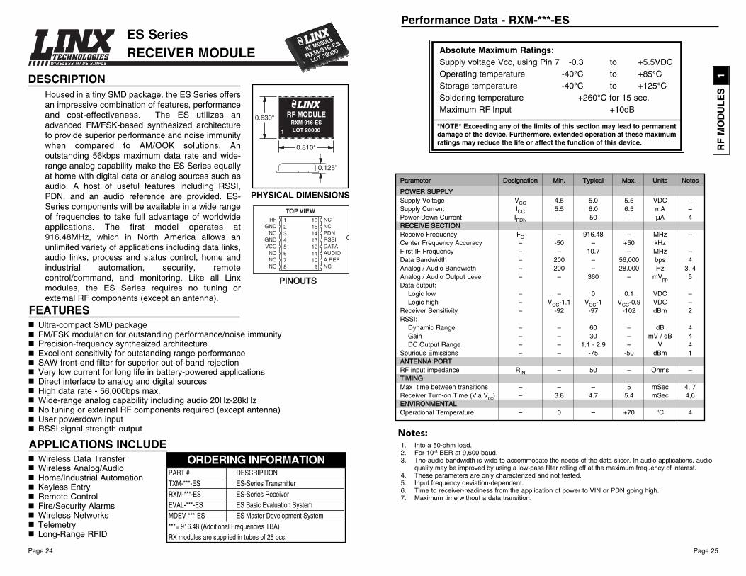
Performance Data - TXM-***-ES
Absolute Maximum Ratings:Supply voltage Vcc, using Pin 7 -0.3 to +4.0VDCOperating temperature -40°C to +85°CStorage temperature -40°C to +125°CSoldering temperature +260°C for 15 sec.
*NOTE* Exceeding any of the limits of this section may lead to permanentdamage of the device. Furthermore, extended operation at these maximumratings may reduce the life or affect the function of this device.
PPaarraammeetteerr DDeessiiggnnaattiioonn MMiinn.. TTyyppiiccaall MMaaxx.. UUnniittss NNootteess
PPOOWWEERR SSUUPPPPLLYYSupply voltage VCC 2.1 3 4 VDCSupply current ICC 5.5 7 8.5 mASleep current ISLP – 90 – µA 7TTRRAANNSSMMIITT SSEECCTTIIOONNTransmit Frequency FC – 916.48 – MHz 4Center Frequency Accuracy -50 – +50 kHz 1Output Power PO -3 0 +4 dBm 2,3Level Adjust 0 65 – dB 2,4,7Harmonic Emissions PH – -55 -47 dBc 2Frequency Deviation 90 110 130 kHz 5Data Bandwidth 200 – 56,000 bps 7Analog / Audio Bandwidth 20 – 28,000 Hz 6,7Data input:
Logic low GND – 0.4 VDC 8Logic high 3 – 5.2 VDC 8
Analog Input 0 – 5 VPP 9AANNTTEENNNNAA PPOORRTTRF input impedance RIN – 50 – Ohms 7TTIIMMIINNGGMax time between transitions – – 5 mSec 7,11Transmitter Turn-on Time 0.1 0.5 1.5 mSec 7,10EENNVVIIRROONNMMEENNTTAALLOperational Temperature 0 – +70 °C 7
1. Center frequency measured while modulated with a 0-5V square wave.2. Into a 50-ohm load.3. LVLADJ open.4. Maximum power when LVLADJ open, minimum power when LVLADJ grounded.5. TXDATA pin modulated with a 0-5V square wave.6. The audio bandwidth is wide to accommodate the needs of the data slicer. 7. These parameters are only characterized and not tested.8. The ES is optimized for both 0-5V and 0-3V modulation when sending digital data. 9. Analog signals including audio should be AC-coupled. 10. Time to transmitter readiness from the application of power to VIN or PDN going high.11. Maximum time without a data transition.
Notes:
ES Series TRANSMITTER MODULE
Ultra-compact SMD packageFM / FSK modulation for performance / noise immunityPrecision-frequency synthesized architecture Excellent sensitivity for outstanding range performanceVery low current for long life in battery-powered applicationsDirect interface to analog and digital sourcesHigh data rate - 56,000bps max.Wide-range analog capability including audio 20Hz-28kHzUser powerdown inputLow-voltage detect and microprocessor clock output on TXCost-effective: low cost vs. performanceNo tuning or external RF components required (except antenna)
Housed in a tiny SMD package, the ES utilizes anadvanced FM / FSK-based synthesizedarchitecture to provide superior performance andnoise immunity when compared to AM / OOKsolutions. An outstanding 56kbps maximum datarate and wide-range analog capability make the ESSeries equally at home with digital data or analogsources such as audio. A host of useful featuresincluding RSSI, PDN, audio reference, LVL ADJ,low voltage detect, and a microprocessor clocksource are provided. ES Series components will beavailable in a wide range of frequencies. The firstmodel operates at 916.48MHz, which, in NorthAmerica, allows an unlimited variety of applicationsincluding data links, audio links, process and statuscontrol, home and industrial automation, security,remote control / command, and monitoring. Like allLinx modules, the ES Series requires no tuning orexternal RF components except an antenna.
Wireless Data TransferAudio / Analog Signal TransferProcess MonitoringHome / Industrial AutomationKeyless EntryRemote Control
Fire / Security AlarmsWireless NetworksRemote Status SensingTelemetryRS-232 / 485 Data LinksMIDI LinksVoice Links / Intercoms
APPLICATIONS INCLUDE
FEATURES
DESCRIPTION
TXM-916-ES
PART # DESCRIPTIONTXM-***-ES ES Series Transmitter RXM-***-ES ES Series ReceiverEVAL-***-ES ES Basic Evaluation SystemMDEV-***-ES ES Master Development System***= 916.48 (Additional Frequencies TBA)TX modules are supplied in tubes of 40 pcs.
ORDERING INFORMATION
PHYSICAL DIMENSIONS
PINOUTS
RF
MO
DU
LE
S1
Page 25Page 24
WIRELESS MADE SIMPLE
Performance Data - RXM-***-ES
1. Into a 50-ohm load.2. For 10-5 BER at 9,600 baud.3. The audio bandwidth is wide to accommodate the needs of the data slicer. In audio applications, audio
quality may be improved by using a low-pass filter rolling off at the maximum frequency of interest.4. These parameters are only characterized and not tested.5. Input frequency deviation-dependent.6. Time to receiver-readiness from the application of power to VIN or PDN going high.7. Maximum time without a data transition.
PPaarraammeetteerr DDeessiiggnnaattiioonn MMiinn.. TTyyppiiccaall MMaaxx.. UUnniittss NNootteess
PPOOWWEERR SSUUPPPPLLYYSupply Voltage VCC 4.5 5.0 5.5 VDC –Supply Current ICC 5.5 6.0 6.5 mA –Power-Down Current IPDN – 50 – µA 4RREECCEEIIVVEE SSEECCTTIIOONNReceive Frequency FC – 916.48 – MHz –Center Frequency Accuracy – -50 – +50 kHzFirst IF Frequency – – 10.7 – MHz –Data Bandwidth – 200 – 56,000 bps 4Analog / Audio Bandwidth – 200 – 28,000 Hz 3, 4Analog / Audio Output Level – – 360 – mVpp 5Data output:
Logic low – – 0 0.1 VDC –Logic high – VCC-1.1 VCC-1 VCC-0.9 VDC –
Receiver Sensitivity – -92 -97 -102 dBm 2RSSI:
Dynamic Range – – 60 – dB 4Gain – – 30 – mV / dB 4DC Output Range – – 1.1 - 2.9 – V 4
Spurious Emissions – – -75 -50 dBm 1AANNTTEENNNNAA PPOORRTTRF input impedance RIN – 50 – Ohms –TTIIMMIINNGGMax time between transitions – – – 5 mSec 4, 7Receiver Turn-on Time (Via Vcc) – 3.8 4.7 5.4 mSec 4,6EENNVVIIRROONNMMEENNTTAALLOperational Temperature – 0 – +70 °C 4
Absolute Maximum Ratings:Supply voltage Vcc, using Pin 7 -0.3 to +5.5VDCOperating temperature -40°C to +85°CStorage temperature -40°C to +125°CSoldering temperature +260°C for 15 sec.Maximum RF Input +10dB
*NOTE* Exceeding any of the limits of this section may lead to permanentdamage of the device. Furthermore, extended operation at these maximumratings may reduce the life or affect the function of this device.
DESCRIPTIONHoused in a tiny SMD package, the ES Series offersan impressive combination of features, performanceand cost-effectiveness. The ES utilizes anadvanced FM/FSK-based synthesized architectureto provide superior performance and noise immunitywhen compared to AM/OOK solutions. Anoutstanding 56kbps maximum data rate and wide-range analog capability make the ES Series equallyat home with digital data or analog sources such asaudio. A host of useful features including RSSI,PDN, and an audio reference are provided. ES-Series components will be available in a wide rangeof frequencies to take full advantage of worldwideapplications. The first model operates at916.48MHz, which in North America allows anunlimited variety of applications including data links,audio links, process and status control, home andindustrial automation, security, remotecontrol/command, and monitoring. Like all Linxmodules, the ES Series requires no tuning orexternal RF components (except an antenna).
FEATURESUltra-compact SMD packageFM/FSK modulation for outstanding performance/noise immunityPrecision-frequency synthesized architecture Excellent sensitivity for outstanding range performanceSAW front-end filter for superior out-of-band rejectionVery low current for long life in battery-powered applicationsDirect interface to analog and digital sourcesHigh data rate - 56,000bps max.Wide-range analog capability including audio 20Hz-28kHzNo tuning or external RF components required (except antenna)User powerdown inputRSSI signal strength output
Wireless Data TransferWireless Analog/Audio Home/Industrial AutomationKeyless EntryRemote ControlFire/Security AlarmsWireless NetworksTelemetryLong-Range RFID
APPLICATIONS INCLUDE
PHYSICAL DIMENSIONS
LOT 20000RXM-916-ES
RF MODULE
PART # DESCRIPTIONTXM-***-ES ES-Series Transmitter RXM-***-ES ES-Series ReceiverEVAL-***-ES ES Basic Evaluation SystemMDEV-***-ES ES Master Development System***= 916.48 (Additional Frequencies TBA)RX modules are supplied in tubes of 25 pcs.
ORDERING INFORMATION
PPIINNOOUUTTSS
ES Series RECEIVER MODULE
Notes:
RF
MO
DU
LE
S1

Page 27Page 26
WIRELESS MADE SIMPLE
Performance Data - TXM-900-HP3
Absolute Maximum Ratings:Supply voltage Vcc, using Pin 7 -0.3 to +18VDCOperating temperature -30°C to +85°CStorage temperature -45°C to +85°CSoldering temperature +260°C for 10 sec.Any input or output pin -0.3 to Vcc
*NOTE* Exceeding any of the limits of this section may lead to permanentdamage of the device. Furthermore, extended operation at these maximumratings may reduce the life or affect the function of this device.
1. Over entire operating voltage range 2. PDN pin low3. Serial Mode 4. 100 Serial channels on PS versions only5. Does not change over 3-13VDC supply 6. Into 50 Ohms7. Receiver will not reliably hold a DC level. See RX manual for minimum transition rate.8. Voltage specified is modulation pin voltage
Notes:
PPaarraammeetteerr DDeessiiggnnaattiioonn MMiinn.. TTyyppiiccaall MMaaxx.. UUnniittss NNootteess
PPOOWWEERR SSUUPPPPLLYYSupply Voltage VCC 2.8 – 13.0 VDC –Supply Current ICC – 14 17 mA 1Power-Down Current IPDN – – 15 µA 2TTRRAANNSSMMIITT SSEECCTTIIOONNTransmit Frequency Range FC 902.62 – 927.62 MHz 3Center Frequency Accuracy – -50 – +50 kHz –Available Channels – 8 (Par.) – 100 (Ser.) – 4Channel Spacing – – 250 – kHz –Occupied Bandwidth – – 115 140 kHz –Output Power – -3 0 +3 dBm 5Spurious Emissions – – -45 – dBm 6Harmonic Emissions – – -60 -47 dBm 6Data Bandwidth – 100 – 56,000 bps 7Analog / Audio Bandwidth – 50 – 28,000 Hz 7Data input:
Logic low – GND – 0.5 VDC –Logic high – 2.8 – 5.2 VDC –
Data Input Impedance – – 200 – kOhms –Frequency Deviation @ 3VDC – 60 70 110 kHz 8Frequency Deviation @ 5VDC – 90 115 140 kHz 8AANNTTEENNNNAA PPOORRTTRF input impedance RIN – 50 – Ohms –TTIIMMIINNGGTransmitter Turn-on Time T1 – 7 10 mSec –Max Channel-Change Time T2 – 1 1.5 mSec –EENNVVIIRROONNMMEENNTTAALLOperational Temperature – -30 – +85 °C –
HP-3 SERIESTRANSMITTER MODULE
DESCRIPTIONThe HP-3 RF transmitter module is the thirdgeneration of the popular HP Series and offerscomplete compatibility and numerousenhancements over previous generations. Like itspredecessors, the HP-3 is designed for the cost-effective, high-performance wireless transfer ofanalog or digital information in the popular 902-928MHz band. All HP-3 Series parts continue tofeature eight parallel selectable channels, butversions are also available which add serialselection of 100 channels. To ensure reliableperformance, the transmitter employs FM / FSKmodulation and a microprocessor-controlledsynthesized architecture. The transmitter is pin- andfootprint-compatible with all previous generationsbut its overall physical size has been reduced. BothSMD and pinned packages are now available. When paired with an HP-3 receiver,a reliable link is created for transferring analog and digital information up to 1000feet. (under optimal conditions). Like all Linx modules, the HP-3 requires no tuningor additional RF components (except an antenna), making integrationstraightforward, even for engineers without prior RF experience.
FEATURES8 parallel, 100 serial (PS Versions) User-Selectable Channels Precision Frequency Synthesized ArchitectureFM / FSK Modulation For Outstanding Performance and Noise ImmunityTransparent Analog / Digital InterfaceWide-Range Analog Capability Including Audio (50Hz-28kHz)Extended Temperature Range (-30°C to +85°C)No External RF Components Required (Except Antenna)Compatible With Previous HP Series ModulesPower-Down and CTSFunctionsWide Supply Range (2.8-13VDC) Cost-EffectivePinned or SMD PackagingHigh Data Rate (up to 56kbps)No Production Tuning
APPLICATIONS INCLUDEWireless Data TransferWireless Analog / AudioHome / Industrial AutomationWireless NetworksRemote Control Remote AccessRemote Monitoring / TelemetryAlarm / Security SystemsLong-Range RFIDMIDI LinksVoice / Music / Intercom Links
PHYSICAL DIMENSIONS
0.178"
1.290"
0.680"
LOT 100001
HP SERIES RF TRANSMITTERTXM-900-HP3-PP*
““PP”” SSttyyllee
““SS”” SSttyyllee
PART # DESCRIPTIONTXM-900-HP3-PPO HP-3 Transmitter (PINNED 8 CH only)TXM-900-HP3-PPS HP-3 Transmitter (PINNED 8p / 100s CH)TXM-900-HP3-SPO HP-3 Transmitter (SMD 8 CH only)TXM-900-HP3-SPS HP-3 Transmitter (SMD 8p / 100s CH)MDEV-900-HP3-PPS-USB Development Kit 900MHz (Pinned Pkg.)MDEV-900-HP3-PPS-RS232 Development Kit 900MHz (Pinned Pkg.)MDEV-900-HP3-SPS-USB Development Kit 900MHz (SMD Pkg.)MDEV-900-HP3-SPS-RS232 Development Kit 900MHz (SMD Pkg.)TX modules are supplied in tubes of 15 pcs
ORDERING INFORMATION
0.150"
0.628"
1.260"
LOT 100001
HP SERIES RF TRANSMITTERTXM-900-HP3-SP*
RF
MO
DU
LE
S1
Page 29Page 28
WIRELESS MADE SIMPLE
Performance Data - RXM-900-HP3
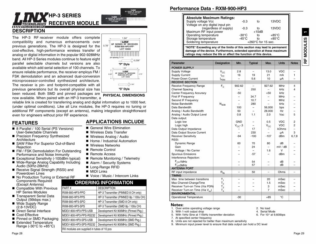
PPaarraammeetteerr DDeessiiggnnaattiioonn MMiinn.. TTyyppiiccaall MMaaxx.. UUnniittss NNootteess
PPOOWWEERR SSUUPPPPLLYYSupply Voltage VCC 2.8 – 13.0 VDC –Supply Current ICC 16 19 21 mA 1Power-Down Current IPDN – 5.6 10 µA –RREECCEEIIVVEE SSEECCTTIIOONNReceive Frequency Range FC 902.62 – 927.62 MHz 4Channel Spacing – 250 – kHz 4Center Frequency Accuracy -50 +50 kHzFirst IF Frequency – 34.7 – MHz –Second IF Frequency – 10.7 – MHz –Noise Bandwidth N3DB – 280 – kHz –Data Bandwidth 100 – 56,000 bps –Analog / Audio Bandwidth 50 – 28,000 Hz –Analog / Audio Output Level 0.8 1.1 2.0 Vac 5Data output:
Logic low GND – 0.5 VDC 2Logic high VCC-.3 – VCC VDC 2
Data Output Impedance – 17 – kOhms –Data Output Source Current – 230 – µA 3Receiver Sensitivity -94 -100 -107 dBm 6,7,8RSSI:
Dynamic Range 60 70 80 dB –Gain – 24 – mV / dB –Voltage / No Carrier – – 1.6 V –
Spurious Emissions – -57 – dBm –Interference Rejection:
FC±1MHz – 54 – dB –FC±5MHz – 57 – dB –
AANNTTEENNNNAA PPOORRTTRF input impedance RIN – 50 – Ohms –TTIIMMIINNGGMax time between transitions T1 – – 20 mSec –Max Channel-ChangeTime T2 – – 1.5 mSec –Receiver Turn-on Time (Via PDN) T3 – – 3 mSec –Receiver Turn-on Time (Via Vcc) T4 – – 7 mSec –EENNVVIIRROONNMMEENNTTAALLOperational Temperature -30 +85 °C
Notes:1. Over entire operating voltage range 2. No load3. With 1-volt output drop 4. Serial Mode5. With 1kHz Sine at 115kHz transmitter deviation 6. For 10-5 at 9,600bps7. At specified center frequency8. Units are not rejected for better than maximum sensitivity9. Minimum input power level to ensure that data output can hold a DC level
Absolute Maximum Ratings:Supply voltage Vcc -0.3 to 13VDCVoltage on any digital input pin
(regardless of supply) -0.3 to 13VDCMaximum RF input power +10dBOperating temperature -30°C to +85°CStorage temperature -45°C to +85°CSoldering temperature +260°C for 15 sec.
*NOTE* Exceeding any of the limits of this section may lead to permanentdamage of the device. Furthermore, extended operation at these maximumratings may reduce the life or affect the function of this device.
HP-3 SERIESRECEIVER MODULE
APPLICATIONS INCLUDEGeneral Wire EliminationWireless Data TransferWireless Analog / AudioHome / Industrial AutomationWireless NetworksRemote Control Remote AccessRemote Monitoring / TelemetryAlarm / Security SystemsLong-Range RFIDMIDI LinksVoice / Music / Intercom Links
FEATURES8 Parallel / 100 Serial (PS Versions) User-Selectable ChannelsPrecision Frequency Synthesized ArchitectureSAW Filter For Superior Out-of-Band RejectionFM / FSK Demodulation For Outstanding Performance and Noise ImmunityExceptional Sensitivity (-100dBm typical)Wide-Range Analog Capability Including Audio (50Hz-28kHz)Receive Signal Strength (RSSI) and Powerdown LinesNo Production Tuning or External RF Components Required (Except Antenna)Compatible With Previous HP Series ModulesTransparent Serial Data Output (56kbps max.)Wide Supply Range(2.8-13VDC) Direct Serial InterfaceCost-EffectivePinned or SMD PackagingExtended Temperature Range (-30°C to +85°C)
DESCRIPTIONThe HP-3 RF receiver module offers completecompatibility and numerous enhancements overprevious generations. The HP-3 is designed for thecost-effective, high-performance wireless transfer ofanalog or digital information in the popular 902-928MHzband. All HP-3 Series modules continue to feature eightparallel selectable channels but versions are alsoavailable which add serial selection of 100 channels. Toensure reliable performance, the receiver employs FM /FSK demodulation and an advanced dual-conversionmicroprocessor-controlled synthesized architecture.The receiver is pin- and footprint-compatible with allprevious generations but its overall physical size hasbeen reduced. Both SMD and pinned packages arenow available. When paired with an HP-3 transmitter, areliable link is created for transferring analog and digital information up to 1000 feet.(under optimal conditions). Like all Linx modules, the HP-3 requires no tuning oradditional RF components (except an antenna), making integration straightforwardeven for engineers without prior RF experience.
PHYSICAL DIMENSIONS
0.236"
1.94"
0.78"LOT 10000
HP SERIES RF RECEIVERRXM-900-HP3-PP*
0.190"
0.75"
1.95"
0.69"
LOT 10000
HP SERIES RF RECEIVERRXM-900-HP3-SP*
1
““PP”” SSttyyllee
““SS”” SSttyyllee
PART # DESCRIPTIONRXM-900-HP3-PPO HP-3 Transmitter (PINNED 8 CH only)RXM-900-HP3-PPS HP-3 Transmitter (PINNED 8p / 100s CH)RXM-900-HP3-SPO HP-3 Transmitter (SMD 8 CH only)RXM-900-HP3-SPS HP-3 Transmitter (SMD 8p / 100s CH)MDEV-900-HP3-PPS-USB Development Kit 900MHz (Pinned Pkg.)MDEV-900-HP3-PPS-RS232 Development Kit 900MHz (Pinned Pkg.)MDEV-900-HP3-SPS-USB Development Kit 900MHz (SMD Pkg.)MDEV-900-HP3-SPS-RS232 Development Kit 900MHz (SMD Pkg.)RX modules are supplied in tubes of 10 pcs
ORDERING INFORMATION
RF
MO
DU
LE
S1
Page 31Page 30
WIRELESS MADE SIMPLE
1. Center frequency measured while modulated with a 0-5V square wave.2. Into a 50-ohm load3. LVLADJ open4. Maximum power when LVLADJ open, minimum power when LVLADJ grounded5. TXDATA pin modulated with a 0-5V square wave.6. For 10-5 BER at 9,600 baud7. The audio bandwidth is wide to accommodate the needs of the data slicer. In audio applications, audio
quality may be improved by using a low-pass filter rolling off at the maximum frequency of interest.8. These parameters are only characterized and not tested. 9. The SC is optimized for 0-5V modulation when sending digital data. 0-3V modulation is possible but
will slightly reduce system sensitivity and increase settling times.10. Analog signals including audio should be AC-coupled. Signals in excess of 3V will cause distortion.11. Time to transmitter or receiver readiness from the application of power to VIN or PDN going high12. Time from the TXEN going high and RXEN going low to the transmitter being ready to transmit data13. Time from the RXEN going high and TXEN going low to valid receiver data output14. Maximum time without a data transition
Performance Data - TR-916-SC-P
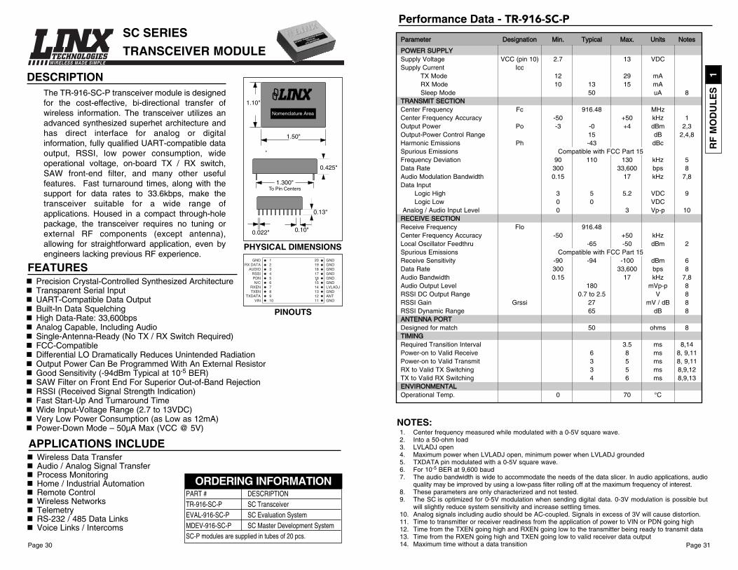
PPaarraammeetteerr DDeessiiggnnaattiioonn MMiinn.. TTyyppiiccaall MMaaxx.. UUnniittss NNootteess
PPOOWWEERR SSUUPPPPLLYYSupply Voltage VCC (pin 10) 2.7 13 VDCSupply Current Icc
TX Mode 12 29 mARX Mode 10 13 15 mASleep Mode 50 uA 8
TTRRAANNSSMMIITT SSEECCTTIIOONNCenter Frequency Fc 916.48 MHzCenter Frequency Accuracy -50 +50 kHz 1Output Power Po -3 -0 +4 dBm 2,3Output-Power Control Range 15 dB 2,4,8Harmonic Emissions Ph -43 dBcSpurious Emissions Compatible with FCC Part 15Frequency Deviation 90 110 130 kHz 5Data Rate 300 33,600 bps 8Audio Modulation Bandwidth 0.15 17 kHz 7,8Data Input
Logic High 3 5 5.2 VDC 9Logic Low 0 0 VDC
Analog / Audio Input Level 0 3 Vp-p 10RREECCEEIIVVEE SSEECCTTIIOONNReceive Frequency Flo 916.48Center Frequency Accuracy -50 +50 kHzLocal Oscillator Feedthru -65 -50 dBm 2Spurious Emissions Compatible with FCC Part 15Receive Sensitivity -90 -94 -100 dBm 6Data Rate 300 33,600 bps 8Audio Bandwidth 0.15 17 kHz 7,8Audio Output Level 180 mVp-p 8RSSI DC Output Range 0.7 to 2.5 V 8RSSI Gain Grssi 27 mV / dB 8RSSI Dynamic Range 65 dB 8AANNTTEENNNNAA PPOORRTTDesigned for match 50 ohms 8TTIIMMIINNGGRequired Transition Interval 3.5 ms 8,14Power-on to Valid Receive 6 8 ms 8, 9,11Power-on to Valid Transmit 3 5 ms 8, 9,11RX to Valid TX Switching 3 5 ms 8,9,12TX to Valid RX Switching 4 6 ms 8,9,13EENNVVIIRROONNMMEENNTTAALLOperational Temp. 0 70 °C
DESCRIPTIONThe TR-916-SC-P transceiver module is designedfor the cost-effective, bi-directional transfer ofwireless information. The transceiver utilizes anadvanced synthesized superhet architecture andhas direct interface for analog or digitalinformation, fully qualified UART-compatible dataoutput, RSSI, low power consumption, wideoperational voltage, on-board TX / RX switch,SAW front-end filter, and many other usefulfeatures. Fast turnaround times, along with thesupport for data rates to 33.6kbps, make thetransceiver suitable for a wide range ofapplications. Housed in a compact through-holepackage, the transceiver requires no tuning orexternal RF components (except antenna),allowing for straightforward application, even byengineers lacking previous RF experience.
FEATURESPrecision Crystal-Controlled Synthesized ArchitectureTransparent Serial InputUART-Compatible Data OutputBuilt-In Data SquelchingHigh Data-Rate: 33,600bps Analog Capable, Including AudioSingle-Antenna-Ready (No TX / RX Switch Required)FCC-CompatibleDifferential LO Dramatically Reduces Unintended RadiationOutput Power Can Be Programmed With An External ResistorGood Sensitivity (-94dBm Typical at 10-5 BER)SAW Filter on Front End For Superior Out-of-Band RejectionRSSI (Received Signal Strength Indication)Fast Start-Up And Turnaround TimeWide Input-Voltage Range (2.7 to 13VDC)Very Low Power Consumption (as Low as 12mA)Power-Down Mode – 50µA Max (VCC @ 5V)
Wireless Data TransferAudio / Analog Signal TransferProcess MonitoringHome / Industrial AutomationRemote ControlWireless NetworksTelemetryRS-232 / 485 Data LinksVoice Links / Intercoms
APPLICATIONS INCLUDE
1.50"
1.10"
Nomenclature Area
SC SERIES
TRANSCEIVER MODULE
PHYSICAL DIMENSIONS
0.13"
0.425"
1.300"To Pin Centers
0.10"0.022"
PART # DESCRIPTIONTR-916-SC-P SC TransceiverEVAL-916-SC-P SC Evaluation SystemMDEV-916-SC-P SC Master Development SystemSC-P modules are supplied in tubes of 20 pcs.
ORDERING INFORMATION
PINOUTS
GNDRX DATA
AUDIORSSIPDNN/C
RXENTXEN
TXDATAVIN
GNDGNDGNDGNDGNDGNDLVLADJGNDANTGND
12345678910
20191817161514131211
NOTES:
RF
MO
DU
LE
S1

Page 33Page 32
WIRELESS MADE SIMPLE
1. Center frequency measured while modulated with a 0-5V square wave.2. Into a 50-ohm load3. LVLADJ open4. Maximum power when LVLADJ open, minimum power when LVLADJ grounded5. TXDATA pin modulated with a 0-5V square wave.6. For 10-5 BER at 9,600 baud7. The audio bandwidth is wide to accommodate the needs of the data slicer. In audio applications, audio
quality may be improved by using a low-pass filter rolling off at the maximum frequency of interest.8. These parameters are only characterized and not tested.9. The SC-PA is optimized for 0-5V modulation when sending digital data. 0-3V modulation is possible but
will slightly reduce system sensitivity and increase settling times.10. Analog signals including audio should be AC-coupled. Signals in excess of 3V will cause distortion.11. Time to transmitter or receiver readiness from the application of power to VIN or PDN going high12. Time from the TXEN going high and RXEN going low to the transmitter being ready to transmit data13. Time from the RXEN going high and TXEN going low to valid receiver data output14. Maximum time without a data transition
Performance Data - TR-916-SC-PAPPaarraammeetteerr DDeessiiggnnaattiioonn MMiinn.. TTyyppiiccaall MMaaxx.. UUnniittss NNootteess
PPOOWWEERR SSUUPPPPLLYYSupply Voltage VCC (pin 10) 2.7 13 VDCSupply Current Icc
TX Mode 12 15 19 mARX Mode 10 13 15 mASleep Mode 50 uA 8
TTRRAANNSSMMIITT SSEECCTTIIOONNCenter Frequency Fc 916.48 MHzCenter Frequency Accuracy -50 +50 kHz 1Output Power Po -12 -10 -6 dBm 2,3Output-Power Control Range 5 dB 2,4,8Harmonic Emissions Ph -45 dBcSpurious Emissions Compatible with FCC Part 15Frequency Deviation 90 110 130 kHz 5Data Rate 300 33,600 bps 8Audio Modulation Bandwidth 0.15 17 kHz 7,8Data Input
Logic High 3 5 5.2 VDC 9Logic Low 0 0 VDC
Analog / Audio Input Level 0 3 Vp-p 10RREECCEEIIVVEE SSEECCTTIIOONNReceive Frequency Flo 916.48Center Frequency Accuracy -50 +50 kHzLocal Oscillator Feedthru -65 -50 dBm 2Spurious Emissions Compatible with FCC Part 15Receive Sensitivity -90 -94 -100 dBm 6Data Rate 300 33,600 bps 8Audio Bandwidth 0.15 17 kHz 7,8Audio Output Level 180 mVp-p 8RSSI DC Output Range 0.7 to 2.5 V 8RSSI Gain Grssi 27 mV / dB 8RSSI Dynamic Range 65 dB 8AANNTTEENNNNAA PPOORRTTDesigned for match 50 ohms 8TTIIMMIINNGGRequired Transition Interval 3.5 ms 8,14Power-on to Valid Receive 6 8 ms 8, 9,11Power-on to Valid Transmit 3 5 ms 8, 9,11RX to Valid TX Switching 3 5 ms 8,9,12TX to Valid RX Switching 4 6 ms 8,9,13EENNVVIIRROONNMMEENNTTAALLOperational Temp. 0 70 °C
DESCRIPTIONThe PA version of Linx popular SC Series greatlyreduces the time and expense of making a productwireless. That is because it is pre-approved by theFCC when used with the appropriate proprietaryantennas. The transceiver is designed for the cost-effective, bi-directional transfer of analog & digitalinformation. Housed in a compact through-holepackage, it utilizes an advanced synthesizedsuperhet architecture and has direct interface foranalog or digital information, fully qualified UART-compatible data output, RSSI, low powerconsumption, wide operational voltage, on-boardTX / RX switch, SAW front-end filter, and manyother useful features. Fast turnaround times, alongwith the support for data rates to 33.6kbps, makethe transceiver suitable for a wide range ofapplications. The transceiver requires no tuning orexternal RF components, except an antenna,making integration straightforward.
FEATURES
Wireless Data TransferAudio / Analog Signal TransferProcess MonitoringHome / Industrial AutomationRemote ControlWireless NetworksTelemetryRS-232 / 485 Data LinksVoice Links / Intercoms
APPLICATIONS INCLUDE
SC SERIES PRECERTIFIED
TRANSCEIVER MODULE
PHYSICAL DIMENSIONS
PINOUTS
GNDRX DATA
AUDIORSSIPDNN/C
RXENTXEN
TXDATAVIN
GNDGNDGNDGNDGNDGNDLVLADJ
12345678910
20191817161514131211
PART # DESCRIPTIONTR-916-SC-PA SC TransceiverEVAL-916-SC-PA SC Evaluation SystemMDEV-916-SC-PA SC Master Development SystemSC-PA modules are supplied in tubes of 20 pcs.
ORDERING INFORMATION
FCC-Precertified For Immediate IntegrationPrecision Crystal-Controlled Synthesized ArchitectureTransparent Serial InputUART-Compatible Data OutputBuilt-In Data SquelchingHigh Data Rate: 33,600bps Can Transmit Intercom-Quality AudioSingle Antenna Ready (No TX / RX Switch Required)Differential LO Dramatically Reduces Unintended RadiationOutput Power Can Be Programmed With An External ResistorGood Sensitivity (-94dBm Typical at 10-5 BER)SAW Filter on Front End For Superior Out-of-Band RejectionRSSI (Received Signal Strength Indication)Fast Start-Up And Turnaround TimeWide Input-Voltage Range (2.7 to 13VDC)Very Low Power Consumption (as Low as 12mA)Power-Down Mode – 50µA Max (VCC @ 5V)
0.05"
0.425"
1.300"To Pin Centers
0.13"
0.10"0.022"
0.375"
0.175"
∅ .325"
0.90"
1.50"
1.10"
Nomenclature Area
NOTES:
RF
MO
DU
LE
S1

Page 35
Performance Data - TR-916-SC-S
1. Center frequency measured while modulated with a 0-5V square wave.2. Into a 50-ohm load3. LVLADJ open4. Maximum power when LVLADJ open, minimum power when LVLADJ grounded5. TXDATA pin modulated with a 0-5V square wave.6. For 10-5 BER at 9,600 baud7. The audio bandwidth is wide to accommodate the needs of the data slicer. In audio applications, audio
quality may be improved by using a low-pass filter rolling off at the maximum frequency of interest.8. These parameters are only characterized and not tested.9. The SC-PA is optimized for 0-5V modulation when sending digital data. 0-3V modulation is possible
but will slightly reduce system sensitivity and increase settling times.10. Analog signals including audio should be AC-coupled. Signals in excess of 3V will cause distortion.11. Time to transmitter or receiver readiness from the application of power to VIN or PDN going high12. Time from the TXEN going high and RXEN going low to the transmitter being ready to transmit data13. Time from the RXEN going high and TXEN going low to valid receiver data output14. Maximum time without a data transition
PPaarraammeetteerr DDeessiiggnnaattiioonn MMiinn.. TTyyppiiccaall MMaaxx.. UUnniittss NNootteess
PPOOWWEERR SSUUPPPPLLYYSupply Voltage VCC (pin 10) 2.7 13 VDCSupply Current Icc
TX Mode 12 29 mARX Mode 10 13 15 mASleep Mode 50 uA 8
TTRRAANNSSMMIITT SSEECCTTIIOONNCenter Frequency Fc 916.48 MHzCenter Frequency Accuracy -50 +50 kHz 1Output Power Po -3 -0 +4 dBm 2,3Output-Power Control Range 15 dB 2,4,8Harmonic Emissions Ph -43 dBcSpurious Emissions Compatible with FCC Part 15Frequency Deviation 90 110 130 kHz 5Data Rate 300 33,600 bps 8Audio Modulation Bandwidth 0.15 17 kHz 7,8Data Input
Logic High 3 5 5.2 VDC 9Logic Low 0 0 VDC
Analog / Audio Input Level 0 3 Vp-p 10RREECCEEIIVVEE SSEECCTTIIOONNReceive Frequency Flo 916.48Center Frequency Accuracy -50 +50 kHzLocal Oscillator Feedthru -65 -50 dBm 2Spurious Emissions Compatible with FCC Part 15Receive Sensitivity -90 -94 -100 dBm 6Data Rate 300 33,600 bps 8Audio Bandwidth 0.15 17 kHz 7,8Audio Output Level 180 mVp-p 8RSSI DC Output Range 0.7 to 2.5 V 8RSSI Gain Grssi 27 mV / dB 8RSSI Dynamic Range 65 dB 8AANNTTEENNNNAA PPOORRTTDesigned for match 50 ohms 8TTIIMMIINNGGRequired Transition Interval 3.5 ms 8,14Power-on to Valid Receive 6 8 ms 8, 9,11Power-on to Valid Transmit 3 5 ms 8, 9,11RX to Valid TX Switching 3 5 ms 8,9,12TX to Valid RX Switching 4 6 ms 8,9,13EENNVVIIRROONNMMEENNTTAALLOperational Temp. 0 70 °C
Notes:
Page 34
WIRELESS MADE SIMPLE
SC SERIES SMT
TRANSCEIVER MODULE
DESCRIPTIONThe TR-916-SC-S transceiver module is designed forthe cost-effective, bi-directional transfer of wirelessinformation. The transceiver utilizes an advancedsynthesized superhet architecture and has directinterface for analog or digital information, UART-compatible data output, RSSI, low power consumption,wide operational voltage, on-board TX / RX switch,SAW front-end filter, and many other useful features.Fast turnaround times, along with the support for datarates to 33.6kbps, make the transceiver suitable for awide range of applications. Housed in a compact SMTpackage, the transceiver requires no tuning or externalRF components (except antenna), allowing forstraightforward application, even by engineers lackingprevious RF experience.
FEATURESDirect Interface For Analog or Digital InformationPrecision Crystal-Controlled Synthesized ArchitectureTransparent Serial InputUART-Compatible Data OutputBuilt-In Data SquelchingHigh Data-Rate: Up To 33,600bps Wide-Range Analog Capability Including AudioSingle-Antenna-Ready (No TX / RX Switch Required)Output Power Can Be Programmed With an External ResistorGood Sensitivity (-95dBm typical at 10-5 BER)SAW Filter on Front End For Superior Out-of-Band RejectionReceived Signal Strength IndicationFast Start-Up And Turnaround TimesWide Input-Voltage Range (2.7 to 13VDC)Very Low Power Consumption (as low as 12mA)Power-Down Mode – 50µA max (VCC @ 5V)
Wireless Data TransferAudio / Analog Signal TransferHome / Industrial AutomationRemote ControlWireless NetworksTelemetryRS-232 / 485 Data LinksVoice Links / Intercoms
APPLICATIONS INCLUDE
0.265"
1.055"
1.335"
TR-916-SC-SHYBRID RF TRANSCEIVER
LOT 22000
1
TR-916-SC-SHYBRID RF TRANSCEIVER
LOT 22000
GND
RX DATA
AUDIO
RSSI
PDN
N/C
RXEN
TXEN
TXDATA
VIN
GND
GND
GND
GND
GND
GND
LVLADJ
GND
ANT
GND
1
2
3
4
5
6
7
8
9
10
20
19
18
17
16
15
14
13
12
11
PHYSICAL DIMENSIONS
PINOUTS
PART # DESCRIPTIONTR-916-SC-S SC TransceiverEVAL-916-SC-S SC Evaluation SystemMDEV-916-SC-S SC Master Development SystemSC-S modules are supplied in tubes of 20 pcs.
ORDERING INFORMATION
RF
MO
DU
LE
S1

Page 37
Your Fast Track To Wireless Success
Evaluation / Development Systems put you on the fast track to wireless success.Each kit contains everything necessary to evaluate the Linx module family of yourchoice and then integrate it into your product in record time. Clear documentationwill guide you through the legal and technical issues of application while pre-populated evaluation boards allow immediate module operation under actual fieldconditions. Finally, when you have integrated the modules into your own product,the kit will continue to serve as a valuable benchmark to compare theperformance of your own layout and design. In addition, you’ll receive unlimitedno-charge technical support throughout the entire design process.
*IMPORTANT NOTE*Linx requires the purchase of an evaluation kit of a module Series (LC, LR, KH,RM, ES, HP, SC) prior to selling individual modules of that Series to a user.There are many reasons for this policy, but the most important is that we wantyou to have all the tools necessary to correctly and legally bring wireless functionto your product. Evaluation kits serve as a point of reference among all of ourcustomers and allow us to more effectively assist in explaining layout conceptsor in troubleshooting application difficulties.
EVALUATION SYSTEMS 2
EVALUATION KITSPART# DESCRIPTION PG.EVAL-***-LC LC Basic Evaluation System 38MDEV-***-LC LC Master Development System 38EVAL-***-KH KH Basic Evaluation System 39EVAL-***-KEY-X Keyfob Evaluation System 39EVAL-***-HHTX Full-Size Handheld Eval System 40EVAL-***-HHCP Compact Handheld Eval System 40EVAL-***-HHLR Compact Long-Range Handheld Eval System 40EVAL-***-RM RM Basic Evaluation Kit 40EVAL-***-ES ES Basic Evaluation System 41MDEV-***-ES ES Master Development System 41MDEV-900-HP3-XXX-RS232 HP3 Master Development System (RS232) 42MDEV-900-HP3-XXX-USB HP3 Master Development System (USB) 42EVAL-***-SC-XX SC Basic Evaluation System 43MDEV-***-SC-XX SC Master Development System 43*** See Order Info for available frequencies
Page 36
NEW
NEW

Page 39
PART # DESCRIPTIONEVAL-***-KEY-X Keyfob Evaluation System*** = Frequency - 315, 418 (Standard) , 433MHz x = Number of buttons from 1 to 5
ORDERING INFORMATION
KH SERIES EVALUATION SYSTEMThis kit allows rapid evaluation of the KH Seriesand serves as a valuable reference during thedesign process. The kit features pre-builtevaluation boards for range testing andbenchmarking. Additional modules andguidelines for integrating KH Series modulesinto your own design are also included.
RF MODULEEVALUATION/DEVELOPMENT KITS
ORDERING INFORMATION
KEYFOB EVALUATION SYSTEMThe new EVAL-***-KEY-X evaluationsystem is an ideal starting point toevaluate the performance of Linx’spopular keyfob transmitters and beginintegration with your own product. TheFCC pre-certified keyfobs allow OEM’s torapidly incorporate wireless functions in awide variety of remote control andcommand applications. The kit containstwo keyfob transmitters, along with a pre-assembled demonstration / developmentboard based on the KH Series receiver / decoder module. The developmentboard features audible and visual indication for range testing and a smallprototyping area with signal breakout header for the user's circuit.
PART # DESCRIPTION EVAL-315-KH KH Basic Evaluation System - 315 MHzEVAL-418-KH KH Basic Evaluation System - 418 MHzEVAL-433-KH KH Basic Evaluation System - 433 MHz
Basic Kit Includes2 Assembled Eval. Boards2 TX / Encoder Modules*2 RX / Decoder Modules*2 CW Series AntennasLithium BatteriesTX+RX Data GuidesFCC Part 2 + Part 15 Guidelines
Keyfob Kit Includes2 Five-Button Keyfobs1 Assembled RX Eval. board2 KH Receiver Modules*1 CW Series Antenna1 Ea. Keyfob and KH RX ManualsPart 2 + Part 15 GuidelinesFree Technical Support
* Listed quantity includes those populated on demo / eval. boards.Page 38
WIRELESS MADE SIMPLEWIRELESS MADE SIMPLE
RF MODULEEVALUATION / DEVELOPMENT KITS
LC SERIES BASIC EVALUATION SYSTEMThis kit is a quick way to evaluate the fieldperformance of the popular LC module Series andverify the performance of your own design. The kitdoes not allow for the level of testing that our MasterKit does, but it is a cost-effective starting pointparticularly for remote-control applications.
Basic Kit Includes2 Fully Assembled Evaluation Boards2 Transmitter Modules*2 Receiver Modules*2 Bronze Rod Antennas1 Ea. Tx and Rx ManualsPart 2 + Part 15 GuidelinesFree Technical Support
PART # DESCRIPTION MDEV-***-LC LC Master Development System*** = Frequency 315, 418, 433.92 MHz
ORDERING INFORMATION
LC MASTER EVALUATION / DEVELOPMENT SYSTEMThese kits provide the most completeopportunity to evaluate the Linx LCSeries and then begin integration intoyour own design. The kit not onlyallows for full evaluation of the LCmodules, but also speeds thedevelopment of your own design viathe included boardset which featuresan onboard prototyping area andbreakout headers.
Master Kit Includes2 Fully Assembled DevelopmentBoards with Prototyping Area2 Transmitter Modules*2 Receiver Modules*2 9V Batteries2 CW Series Antennas1 Ea. Tx and Rx ManualsPart 2 + Part 15 GuidelinesFree Technical Support
* Listed quantity includes those populated on demo / eval. boards.
FeaturesOn-Board Encoder / Decoder IC’sRelay Output for External Loads High-Output Buzzer for Range TestingEfficient 1/4-Wave AntennasUser Prototyping Area5V On-Board RegulationAssembled for Immediate UseRS-232 Interface
PART # DESCRIPTION EVAL-315-LC-* LC Basic Evaluation System- 315 MHzEVAL-418-LC-* LC Basic Evaluation System- 418 MHzEVAL-433-LC-* LC Basic Evaluation System- 433 MHz* = P for Pinned Receiver or S for SMD Receiver
ORDERING INFORMATION
EV
AL
UA
TIO
N/S
YS
TE
MS
2

Page 41
RF MODULEEVALUATION / DEVELOPMENT KITS
ES SERIES BASIC EVALUATION SYSTEMThis kit is a quick way to evaluate the fieldperformance of the popular ES Series modules. Thekit does not allow for the level of development thatour Master Kit does, but it is a cost-effective startingpoint for many basic applications. The developmentboards features audible and visual indication forrange testing and a small prototyping area withsignal breakout header for the user's circuit.
ES Basic Kit Includes2 Assembled Evaluation Boards2 Transmitter Modules*2 Receiver Modules*2 CW Series Antennas2 Batteries1 Ea. Tx and Rx ManualsPart 2 + Part 15 GuidelinesFree Technical Support
PART # DESCRIPTION MDEV-916-ES ES Master Development System - 916.48MHz
ORDERING INFORMATION
ES MASTER EVALUATION / DEVELOPMENT SYSTEMThis kit provides the most completeopportunity to evaluate the Linx ESSeries modules and then begin theintegration of it into your own design.The kit not only allows for full evaluationof the ES modules, but also speeds thedevelopment of your own design via theincluded boardset, which features anonboard prototyping area, RS-232interface and breakout headers. Features
RS-232 InterfaceDemonstration SoftwareOn-Board Encoder / Decoder IC’sRelay Output for External Loads High-Output Buzzer for Range TestingEfficient 1/4-Wave AntennasUser Prototyping Area5V On-Board RegulationPre-Assembled for Immediate Use
ES Master Kit Includes2 Assembled Development Boards2 Transmitter Modules*2 Receiver Modules*1 Software / Documentation CD2 9V Batteries2 CW Series Antennas1 Ea. Tx and Rx ManualsPart 2 + Part 15 GuidelinesFree Technical Support
PART # DESCRIPTION EVAL-916-ES ES Basic Evaluation System- 916.48 MHz
ORDERING INFORMATION
* Listed quantity includes those populated on demo / eval. boards.Page 40
WIRELESS MADE SIMPLEWIRELESS MADE SIMPLE
RF MODULEEVALUATION / DEVELOPMENT KITS
HANDHELD SERIES BASIC EVALUATION KITThis basic development system allowsfor rapid testing of Linx's popularhandheld transmitters, and speedsintegration into your own product. TheFCC pre-certified HHLR, HHCP andHHTX transmitters allow OEM’s torapidly incorporate wireless functions ina wide variety of wireless products. Thekit contains two HH Series transmitters,along with a pre-assembled demon-stration / development board based on the KH Series receiver / decoder module.An antenna, battery, extra KH receiver / decoder and full documentation are alsoprovided. Customization of the Handheld Series' button area is available on OEMorders.
Basic Kit Includes2 HH Series Transmitters2 KH Receiver Modules1 Antenna, 1 Fully AssembledEvaluation BoardHH and KXRX Data GuidesPart 2 + Part 15 GuidelinesFree Technical Support
PART # DESCRIPTIONEVAL-***-HHTX Full-Size Handheld Eval SystemEVAL-***-HHCP Compact Handheld Eval SystemEVAL-***-HHLR Compact Long-Range Handheld Eval System*** = Frequency - 315, 418 (Standard) , 433MHz
ORDERING INFORMATION
The EVAL-***-RM is a cost-effective way to evaluate theRM Series and begin integrating it into your own product.The kit features an on-board encoder / decoder withbuzzer and relay outputs that allow range andinterference testing in anticipated use environments.When you are ready to begin development, a convenientprototyping area with breakout headers and regulatedpower supply allows for rapid testing and interface.
Basic Kit Includes2 Assembled Evaluation / Proto boards2 RM Series Transmitter Modules2 RM Series Receiver Modules2 CW Series Antennas2 9V BatteriesDetailed Data GuidesFCC Part 2 + Part 15 Guidelines
RM SERIES BASIC EVALUATION KIT
PART # DESCRIPTION EVAL-***-RM RM Basic Evaluation System *** = 418, 433MHz
ORDERING INFORMATION
EV
AL
UA
TIO
N/S
YS
TE
MS
2

Page 43
The EVAL-***-SC is a cost-effective way toevaluate the SC Series and begin integratingit into your own product. The kit features anon-board encoder / decoder with buzzer andrelay outputs that allow range andinterference testing in anticipated useenvironments. When you are ready to begindevelopment, a convenient prototyping areawith breakout headers and regulated powersupply allows for rapid testing and interface.
Basic Kit Includes2 Assembled Evaluation / Proto boards2 SC Transceiver Modules2 CW or RCS Series Antennas2 Extra RPSMA Antenna Connectors2 9V BatteriesDetailed Data GuidesFCC Part 2 + Part 15 Guidelines
SC SERIES BASIC EVALUATION / DEVELOPMENT SYSTEM
PART # DESCRIPTION MDEV-***-SC-P SC Master Development System MDEV-***-SC-PA SC-PA Master Development System MDEV-***-SC-S SC-S Master Development System *** = 433, 868, 916MHz
ORDERING INFORMATION
RF MODULEEVALUATION / DEVELOPMENT KITS
PART # DESCRIPTION EVAL-***-SC-P SC Basic Evaluation System EVAL-***-SC-PA SC-PA Basic Evaluation System EVAL-***-SC-S SC-S Basic Evaluation System *** = 433, 868, 916MHz
ORDERING INFORMATION
The most complete way to evaluate the SCSeries and then begin the integration of it intoyour own design. The kit allows for fullevaluation of the SC modules, and speeds thedevelopment of your own design via theincluded boardset which features an onboardprototyping area, RS-232 interface andbreakout headers. Windows demonstrationsoftware is included.
SC Master Kit Includes2 Assembled Development Boardsw/Prototyping Area and RS-2324 SC Transceiver Modules1 Software/Support CD2 9V Batteries2 CW- or RCS Series AntennasDetailed ManualsPart 2 & Part 15 GuidelinesFree Technical Support
SC SERIES MASTER EVALUATION / DEVELOPMENT SYSTEM
* Listed quantity includes those populated on demo / eval. boards.Page 42
WIRELESS MADE SIMPLEWIRELESS MADE SIMPLE
HP3 MASTER EVALUATION / DEVELOPMENT SYSTEMThis kit provides a versatile platform toevaluate the Linx HP3 module familyand then begin the integration of it intoyour own design. The kit features anon-board encoder / decoder with buzzerand relay outputs that allow range andinterference testing in anticipated useenvironments. When you are ready tobegin development, a convenientprototyping area with breakout headersand regulated power supply allows forrapid testing and interface. Forapplications requiring softwaredevelopment, RS-232 or USB hostinterface modules and demonstrationsoftware are provided. Finally, whenyou have integrated the modules intoyour own product, the kit will continue toserve as a valuable benchmark tocompare the performance of your ownlayout and design.
HP Master Kit Includes2 Assembled Development Boards2 RS-232 or USB Interface Modules2 Transmitter Modules2 Receiver Modules1 Software / Documentation CD2 CW Series Antennas2 9V Batteries1 Ea. Tx and Rx ManualsPart 2 + Part 15 GuidelinesFree Technical Support
FeaturesOn-Board Encoder / Decoder IC’sRelay Output for External Loads High-Output Buzzer for Range TestingEfficient 1/4-Wave AntennasRS-232 or USB InterfaceUser Prototyping Area5V On-Board RegulationPre-Assembled for Immediate Use
RF MODULEEVALUATION / DEVELOPMENT KITS
Ground Bus
+5V Bus
UserArea
INTEGRATED PROTOTYPING AREA
PART # DESCRIPTIONMDEV-900-HP3-XXX-RS232 HP3 Series Master Development System - RS-232MDEV-900-HP3-XXX-USB HP3 Series Master Development System - USBXXX = SPS or PPS
ORDERING INFORMATION
EV
AL
UA
TIO
N/S
YS
TE
MS
2

Page 45Page 44
Linx offers compact, low-cost RF amplifier modules that are ideally suited to avariety of amplification and buffering applications. The broad bandwidth and gainflatness of the modules allow them to be used over a wide range of frequenciesand applications, including extending the range of Linx’s own RF modules (whenlegally appropriate).
*IMPORTANT NOTE*
Use of these modules may result in the amplification of signals to a level that maybe unacceptable for legal or technical reasons. It is the responsibility of the userto determine and adhere to the appropriate guidelines for the proposedapplication.
RF AMPLIFIERS 3
RF AMPLIFIERSPART# DESCRIPTION PG.BBA-322-A High-Gain RF Amp 46BBA-519-A High-Power RF Amp 46
More Power To You

Page 47Page 46
WIRELESS MADE SIMPLE
All parameters measured at 5.2Volts, 25°C, -30dBm input
Performance Data - BBA-322-A
PPaarraammeetteerrss TTyyppiiccaall UUnniittss NNootteess
Frequency Range 10 to 4000 MHz T=25°C, Icc=65mAGain 18.5 dB Freq=100MHz
17.5 dB Freq=1000MHz15.5 dB Freq=2000MHz13.5 dB Freq=3000MHz12.5 dB Freq=4000MHz
Gain Flatness ±2 dB 100MHz to 2000MHzNoise Figure 4.8 dB Freq=2000MHzInput VSWR 2.1:1 In a 50Wsystem, DC to 4000MHzOutput VSWR 1.8:1 In a 50Wsystem, DC to 4000MHzOutput IP3 +33 dBm Freq=1000MHz±50kHz, PTONE=-10dBmOutput P1dB +18.5 dBm Freq=1000MHzReverse Isolation 20 dB Freq=2000MHzPPOOWWEERR SSUUPPPPLLYYDevice Operating Voltage 4.8-5.2 VDC VCC regulated between 4.8 and 5.2VDC
5.2-12 VDC VCC Range using appropriate current limiting resistor inline with VCC
Max Supply Current 65 mAOperating Current 60 mA @5VDCEENNVVIIRROONNMMEENNTTAALLRated Operating Temperature 0-70 °C
PPaarraammeetteerrss TTyyppiiccaall UUnniittss NNootteess
Frequency Range DC to 3000 MHz T=25°C, Icc=35mAGain 21 dB Freq=100MHz
20 dB Freq=1000MHz17 dB Freq=2000MHz14 dB Freq=3000MHz
Gain Flatness ±2 dB 100MHz to 2000MHzNoise Figure 3.8 dB Freq=2000MHzInput VSWR 2.3:1 In a 50Wsystem, DC to 3000MHzOutput VSWR 2.1:1 In a 50Wsystem, DC to 3000MHzOutput IP3 +22.5 dBm Freq=2000MHz±50kHz, PTONE=-18dBmOutput P1dB +11.2 dBm Freq=2000MHzReverse Isolation 20 dB Freq=2000MHzPPOOWWEERR SSUUPPPPLLYYDevice OperatingVoltage 4.8-5.2 VDC VCC regulated between 4.8 and 5.2VDC
5.2-12 VDC VCC Range using appropriate current limitingresistor inline with VCC
Max Supply Current 65 mAOperating Current 35 mA @ 5VDCEENNVVIIRROONNMMEENNTTAALLRated Operating Temperature 0-70 °C
All parameters measured @ 5.0 Volts, 25°C, -50dBm input
TX / RX Range Enhancement*IF or RF BufferingDriver or Final Stage for PAGeneral-Purpose Gain Blocks
Applications IncludePrematched for 50Ω Impedance I / ONo External RF Components RequiredExceptional Gain FlatnessCompact Surface-Mount Package(for easy hand or automated mounting)
High-Gain Model10MHz - 3GHz Broadband Operation+20dB Small Signal-Gain at 900MHzUp to +10dB (10mW) Linear Output Power3.8dB Noise FigureOperates From a Single Supply
BBA-322 Features
BBA-519 FeaturesHigh-Output Model10MHz - 4GHz Broadband Operation+18dB Small Signal-Gain at 900MHzUp to +17dB (50mW) Linear Output-Power4.8dB Noise FigureOperates From a Single Supply
The BBA Series is a family of low-costhigh-performance broadband RFamplifiers. The modules are ideallysuited to a wide range of amplificationand buffering applications includingextending the range of Linx’s own RFmodules (when legally appropriate).Housed in a compact SMD package, thehybrid amps are prematched to 50Ωsource and load impedances and requireno external RF components. Themodules utilize a GaHBT gain stagewhich yields high gain and IP3, excellentflatness and low noise.
RF OUT
GND
GND
GND
TOP VIEW
VCC
GND
GND
RF IN
0.15"3.8mm
0.365"9.5mm
0.505"13mm
PINOUTS
PHYSICAL DIMENSIONS
DESCRIPTION
All BBA Amps Feature
BBA Series
BROADBAND AMPLIFIERS
* The purchaser of this device should beaware that approvals may be required byapplicable governing bodies for systemsproducing RF energy. It is the responsibilityof the user to determine and adhere to theappropriate regulations for the region inwhich operation is intended.
PART # DESCRIPTION BBA-322-A Hi-Gain RF AmpBBA-519-A Hi-Power RF AmpBBA Amplifiers are supplied in tube packaging of 50 pcs.per tube.* The purchaser is responsible to ensure compliance withall appropriate emission standards
ORDERING INFORMATION
Performance Data - BBA-519-A
RF
AM
PL
IFIE
RS
3

Page 49Page 48
The Linx interface modules are designed to reliably convert data from one formto another while quickly and easily integrating into our customer's designs. Thefirst member of the interface family is the QS Series USB module. The QSmodule makes adding a USB interface exceptionally easy by making the USBoperations invisible to the user. This saves development time and costs allowingour customers to bring their products to market quickly and efficiently.
INTERFACE MODULES 4
INTERFACE MODULESPART# DESCRIPTION PG.SDM-USB-QS-S USB Module 50
Interface Made Simple

Page 51
*CAUTION*This product incorporates numerous static-sensitive components.Always wear an ESD wrist strap and observe proper ESDhandling procedures when working with this device. Failure toobserve this precaution may result in module damage or failure.
USBDP
USBDM
GND DSR
DATA_IN
DATA_OUT
RTS
CTS
DTR
TX_IND
VCC
SUSP_IND
RX_IND
485_TX
RI
DCD1
2
3
4
5
6
7
8 9
10
11
12
13
14
15
16
Absolute Maximum Ratings:
Supply voltage VCC -0.5 to +6.0 VDCAny input or output Pin -0.5 to VCC + 0.5 VDCMax Current Sourced By Data Pins 2 mAMax Current Sunk By Data Pins 4 mAOperating temperature 0 to +70 °CStorage temperature -65 to +150 °CSoldering temperature +225°C for 10 seconds
*NOTE* Exceeding any of the limits of this section may lead to permanentdamage to the device. Furthermore, extended operation at these maximumratings may reduce the life of this device.
PPaarraammeetteerr DDeessiiggnnaattiioonn MMiinn.. TTyyppiiccaall MMaaxx.. UUnniittss NNootteess
PPOOWWEERR SSUUPPPPLLYYOperating Voltage VCC 4.4 5.0 5.26 VDC –Supply Current ICC – 26 28 mA –UUAARRTT SSEECCTTIIOONN
Data Rate – – – 3 Mbps –
Data OutputLogic Low VOL 0.1 – 0.7 VDC –Logic High VOH 4.4 – 5 VDC –
EEPROM Size – – 1024 Bits –UUSSBB SSEECCTTIIOONNData Output
Logic Low UVOL 0 – 0.3 VDC –Logic High UVOH 2.8 – 3.6 VDC –
Single Ended RX Threshold – 0.8 – 2.0 VDC –Differential Common Mode – 0.8 – 2.5 VDC –Differential Input Sensitivity – 0.2 – – VDC –EENNVVIIRROONNMMEENNTTAALLOperating Temperature Range – 0 – +70 °C –
Pin Assignments
Performance Data - SDM-USB-QS-S
TOP VIEW
Page 50
WIRELESS MADE SIMPLE
QS SERIES
USB MODULE
The Linx QS Series USB module allows the rapidaddition of USB to virtually any device. Housed ina compact SMD package the QS moduleprovides a complete solution for convertingbetween USB and TTL logic output. The modulecan be directly connected to virtually any serialdevice including microprocessors, RS232/RS485level converters, even Linx wireless RF modules.The QS module is completely self contained andrequires no external components, (except a USBjack) and includes all necessary firmware anddrivers freeing the designer from complicatedprogramming. Power can be supplied externallyor from the USB bus and both USB 1.1 and USB2.0 are supported at data rates to 3Mbps.
0.14"
0.630"
TOP VIEW
SIDE VIEW
LOT 10000SDM-USB-QS1-SUSB MODULE
0.812"
USB to RS232 Converters USB to RS485 ConvertersUSB ModemsInterfacing Microcontrollers To USBInterfacing RF Modules To USBUSB InstrumentationUSB to Serial Converter CablesUpgrade Legacy PeripheralsUSB Smart Card ReadersUSB Game ControllersRobotics
APPLICATIONS INCLUDE
Single Chip USB to Asynchronous Serial Data ConversionLow-Cost 3Mbps baud rateSupports Low-Speed USBFull Handshaking Support For RS232And RS485Bus Or Self Powered
VID, PID, Serial Number, and Descriptors Programmed via USBNo External Components Needed (Except A USB Jack)Compact Surface-mount PackageDrivers And Firmware IncludedSupports Windows 98/2000/ME/XPUSB 1.1 and 2.0 Compatible
FEATURES
DESCRIPTION
PART # DESCRIPTIONSDM-USB-QS-S USB ModuleMDEV-USB-QS Master Development KitQS Modules are supplied in tubes of 25 pcs.
ORDERING INFORMATION
PHYSICAL DIMENSIONS
INT
ER
FA
CE
MO
DU
LE
S4

Page 53
INSTANT RF
PRECERTIFIEDFCC
Instant RF For Your Application
The Linx OEM-configurable RF product line greatly reduces the cost and timerequired to bring a wireless product to market. The line features a variety of low-cost generic command and control modules which can be customized to meetspecific OEM labeling requirements. Since these products have received priorFCC approval, the time and expense of bringing a product to market issignificantly reduced. Available in frequencies from 315-433MHz, the modulesare divided into two classes: command and function modules.
Command modules include complete handheld and keyfob transmitters capableof sending multiple commands to an unlimited number of function modules. Thecommand module’s transmissions may be received by a compatible Linx RFmodule incorporated in a user’s discrete circuit or by a Linx function module.Function modules contain a receiver and decoder to interpret the signal sent bythe command module and then perform switching and control functions. Thecommand module’s transmissions may also be received by the Linx LC, LR, orKH family of RF modules.
COMMAND MODULESPART# DESCRIPTION PG.CMD-KEYx-***-xxx Keyfob Transmitter 54CMD-HHTX-*** -xxx 8-Button Handheld Transmitter 55CMD-HHLR-***-xxx Long-Range OEM Handheld Transmitter 56
CMD-HHCP-***-xxx Compact OEM Handheld Transmitter 57
FUNCTION MODULESPART# DESCRIPTION PG.FCTN-DEC1-*** OEM Decoder Module 58FCTN-WALL-*** AC Function Module 59FCTN-RLY-*** Relay Module 60
*** See Order Info for available frequencies
PRECERTIFIED OEM PRODUCTS 5
NEW
FEATURES

Page 55
WIRELESS MADE SIMPLE
Page 54
WIRELESS MADE SIMPLE
PRECERTIFIED OEMRF PRODUCTS
PRECERTIFIED OEMRF PRODUCTS
OEM Configurations
With a one-time NRE and minimumorder, Linx can configure the keypadand label areas to meet your specificrequirements. Contact Linx for details.
OEM KEYFOB TRANSMITTER
DESCRIPTIONThe Linx CMD-KEYx-*** RemoteCommand Keyfob is ideal for general-purpose remote control and commandapplications. The unit has been pre-certified for FCC Part-15 compliance,which reduces costs and time toproduct introduction. Available in 315,418 or 433.92MHz (418MHz standard),this stylish and compact remote iscapable of 100+ft. transmission range.Keyfob units can be configured with 1-5 buttons and the keypad and labelingcan be customized to meet specificcustomer requirements. Available inblack, white or transparent-neoncolors. Selectable addressing providessecurity and allows for 210 distincttransmitter-receiver relationships. Thetransmission can be decoded using amatching Linx function module, a KHSeries receiver/decoder module or aLinx LC or LR Series receiver pairedwith a decoder IC or microcontroller.The unit operates from a single 3-voltlithium cell.
2.24"(57.4)
0.99"(25.4)
0.45"(11.5)
1.35"(34.6)
S4
S2
S1 S3S5
Remote Control / Command
Keyless Entry
Garage / Gate Openers
Lighting Control
Security / Call Systems
Home / Industrial Automation
APPLICATIONS INCLUDE
Physical Dimensions
OEM Configurations
With a one-time NRE and minimumorder, Linx can configure the keypadand label areas to meet your specificrequirements. Contact Linx for details.
OEM HANDHELD TRANSMITTER
DESCRIPTIONThe Linx CMD-HHTX-*** RemoteCommand Unit is ideal for general-purpose remote control and commandapplications. The unit has been pre-certified for FCC Part-15 compliance,which reduces costs and time toproduct introduction. Available in 315,418 or 433.92MHz (418MHz standard),this compact handheld remote iscapable of 100+ft. transmission ranges.The transmitter unit can be configuredwith 1-8 buttons and the keypad andlabeling can be modified to meetspecific customer requirements.Selectable addressing providessecurity and allows the creation of up to256 distinct transmitter-receiverrelationships. The transmission can bedecoded using a matching Linx functionmodule, a Linx KH Seriesreceiver/decoder or Linx LC or LRSeries receiver paired with a decoderIC or microcontroller. The unit operatesfrom a single 3-volt lithium cell.
0.17"
0.62"
R 0.12"
3.35"
1.81"
General Remote Control
Keyless Entry
Garage / Gate Openers
Lighting Control
Call Systems
Home / Industrial Automation
Wire Elimination
APPLICATIONS INCLUDE
Physical Dimensions
PART # DESCRIPTIONEVAL-***-KEYx Keyfob Evaluation SystemCMD-KEYx-315xxx 315MHz Keyfob TransmitterCMD-KEYx-418xxx 418MHz Keyfob TransmitterCMD-KEYx-433xxx 433MHz Keyfob Transmitterx = # of buttons - insert 1-5xxx indicates transparent color (Blank for standard black):WHT = White CGY = Gray CBL = BlueCRE = Red CPU = Purple
ORDERING INFORMATION
PART # DESCRIPTIONCMD-HHTX-*** 8-Button Handheld TransmitterEVAL-***-HHTX Full Size Handheld Eval System*** = 315, 418 (Standard), 433.92MHz
ORDERING INFORMATION
IN
STANT RF
PRECERTIFIEDFCC
IN
STANT RF
PRECERTIFIEDFCC
OE
M P
RO
DU
CT
S
5

Page 57Page 56
WIRELESS MADE SIMPLE WIRELESS MADE SIMPLE
PRECERTIFIED OEMRF PRODUCTS
PRECERTIFIED OEMRF PRODUCTS
OEM Configurations
With a one-time NRE and minimumorder, Linx can configure thekeypad and label areas to meetyour specific requirements. ContactLinx for details.
OEM LONG-RANGE HANDHELD TRANSMITTER
DESCRIPTIONThe Linx CMD-HHLR-***-xxx RemoteCommand Unit is ideal for generalpurpose remote control and commandapplications requiring longertransmission distances. This unit hasbeen pre-certified for FCC Part-15compliance, which reduces costs andtime to product introduction. Available in315, 418 or 433.92MHz (418MHzstandard), this compact handheld remoteis capable of a 250+ft. transmissionrange. The transmitter unit can beconfigured with 1-8 buttons and thekeypad and labeling can be modified tomeet specific customer requirements.Selectable addressing provides securityand allows the creation of up to 1024distinct transmitter-receiver relationships.Address selection can be easily changedby the user via an externally accessibleDIP switch. The transmission can bedecoded using a matching Linx functionmodule, KH Series receiver/decoder, ora Linx LC or LR Series receiver pairedwith a decoder IC or microcontroller. Theunit operates from a single 3-volt lithiumcell.
0.15"
1.375"
2.75"
1.535"
General Remote Control Keyless EntryGarage / Gate OpenersLighting ControlCall SystemsHome / Industrial AutomationWire Elimination
APPLICATIONS INCLUDE
Physical Dimensions
OEM Configurations
With a one-time NRE and minimumorder, Linx can configure thekeypad and label areas to meetyour specific requirements. ContactLinx for details.
OEM COMPACT HANDHELD TRANSMITTER
DESCRIPTIONThe Linx CMD-HHCP-***-xxx RemoteCommand Unit is ideal for generalpurpose remote control and commandapplications. This unit has beenprecertified for FCC Part-15compliance, which reduces costs andtime to product introduction. Available in315, 418 or 433.92MHz (418MHzstandard), this compact handheldremote is capable of up to 100ft.transmission range.The transmitter unitcan be configured with 1-8 buttons andthe keypad and labeling can bemodified to meet specific customerrequirements. Selectable addressingprovides security and allows thecreation of up to 1024 distincttransmitter-receiver relationships.Address selection can be easilychanged by the user via an externallyaccessible DIP switch. Thetransmission can be decoded using amatching Linx function module, KHSeries receiver/decoder, or a Linx LCor LR Series receiver paired with adecoder IC or microcontroller. The unitoperates from a single 3-volt lithium cell.
General Remote Control Keyless EntryGarage / Gate OpenersLighting ControlCall SystemsHome / Industrial AutomationWire Elimination
APPLICATIONS INCLUDE
Physical Dimensions
PART # DESCRIPTION
CMD-HHCP-***-xxx 8-Button Handheld TransmitterEVAL-***-HHCP HHCP Evaluation System*** = 315, 418 (Standard), 433.92 MHzxxx = Color Leave blank for standard BlackWHT = White CGY= Gray CBL = BlueCRE = Red CPU = Purple
ORDERING INFORMATIONPART # DESCRIPTIONCMD-HHLR-***-xxx 8-Button Handheld TransmitterEVAL-***-HHLR HHLR Evaluation System*** = 315, 418 (Standard), 433.92 MHzxxx = Color Leave blank for standard BlackWHT = White CGY= Gray CBL = BlueCRE = Red CPU = Purple
ORDERING INFORMATIONIN
STANT RF
PRECERTIFIEDFCC IN
STANT RF
PRECERTIFIEDFCC
OE
M P
RO
DU
CT
S
5

DESCRIPTIONThe AC Function Module plugsdirectly into a 110VAC wallreceptacle and is capable ofswitching devices at loads up to 1800watts (15 amps) or 1 HP at 120VAC.Devices connect via a standardNEMA 5-15 North American powerplug. Labeling can be modified tomeet specific customer requirements.The antenna rotates to a variety ofpositions to allow for maximum rangewhen plugged into a power strip orfloor outlet. The unit is pre-approvedas a Class B device to allowimmediate integration and sale inmost OEM products.
Page 58
WIRELESS MADE SIMPLE
Page 59
WIRELESS MADE SIMPLE
PRECERTIFIED OEMRF PRODUCTS
PRECERTIFIED OEMRF PRODUCTS
OEM DECODER MODULE
General Remote Control Keyless EntryGarage / Gate OpenersLighting ControlCall SystemsHome / Industrial AutomationWire Elimination
APPLICATIONS INCLUDE
Pre-Authorized for Immediate IntegrationComplete RF to Data SolutionConvenient Through-hole PackageLow Power ConsumptionSwivel Antenna for Mounting Flexibility8 Data/9 Address Encoder On-board
FEATURES
OEM Configurations
With a one-time NRE andminimum order, Linx canconfigure the keypad andlabel areas to meet yourspecific requirements. ContactLinx for details.
AC FUNCTION MODULE
DESCRIPTIONThe Linx FCTN-DEC1-xxx decoder moduleis ideal for general-purpose remote-controland command applications. When pairedwith a matching Linx command module orLinx KH, LC or LR Series transmitters, themodule is capable of operation at distancesup to 100ft. The module is pre-authorized tomeet FCC requirements, thereby reducingcosts and speeding product introduction.Available in 315, 418 or 433.92MHz(418MHz standard), this decoder modulemounts directly onto an OEM’s PC board.The on-board receiver/decoder combinationprovides eight switched outputs thatcorrespond to the state of the data lines onthe transmitter’s encoder. Nine tri-stateaddress lines are also provided to allow upto 19,683 unique identification codes. Themodule operates from 5VDC at 8mA typical.Header pins on 0.100" centers allow director socketed connection to a user’s PCB. Theintegral antenna tilts and swivels to allowmaximum mounting flexibility.
2.23"
Front
SIDE VIEW
0.95"
4.1"
SIDE VIEW
2.53"
4.1"
0.9"
APPLICATIONS INCLUDELighting controlRemote activationHome/industrial automationProcess controlSecurity
PART # DESCRIPTIONFCTN-DEC1-315 315MHz Decoder ModuleFCTN-DEC1-418 *418MHz Decoder ModuleFCTN-DEC1-433 433.92MHz Decoder Module* = Standard Frequency
ORDERING INFORMATIONPART # DESCRIPTIONFCTN-WALL-315 AC Function Module-315MHzFCTN-WALL-418* AC Function Module-418MHzFCTN-WALL-433 AC Function Module-433MHz* = Standard Frequency
ORDERING INFORMATION
Physical Dimensions
Physical Dimensions
1.58"
0.20"
0.145"
0.170"
0.35"
1.15"
0.06"
0.80
1
2
3
4
5
6
7
8
9
10
20
19
18
17
16
15
14
13
12
11
4.13"(315-433MHz)
0.160"
0.300"
0.100"0.060"
0.26"
0.44"
1.02"
1.04"Pin Dia. .025"
Pin Dia. .032"
0.100" typ
OE
M P
RO
DU
CT
S
5

Page 60
WIRELESS MADE SIMPLE
Page 61
PRECERTIFIED OEMRF PRODUCTS
4 POSITION RELAY FUNCTION MODULE DATA GUIDEDESCRIPTION
The Relay Function Module is a member ofthe Linx pre-certified OEM-configurableproduct line. The modules have beenpreviously tested for FCC compliance andcan be quickly customized to meet aspecific OEM’s labeling requirements. Thisgreatly reduces the time and expense ofbringing an RF-based OEM product tomarket. The Relay Function Modulesprovide 4 latched or momentary relayoutputs that are capable of switchingexternal AC- or DC-powered loads up to 5amps. The Function Modules incorporate aLinx LC Series receiver and an on-boardHoltek decoder IC. Selectable addressingprovides security and allows the creation ofdistinct transmitter/receiver relationships to avoid unwanted interaction whenmultiple systems are in use. When paired with a Linx command module, a KHSeries transmitter/encoder, or an LC or LR transmitter using a Holtek encoderIC, the Relay Function Module serves as a reliable short-range switching device.
APPLICATIONS INCLUDELighting controllers
Motor control
Industrial control
Remote control/command
Wire elimination
Pre-authorized for immediate integration
Wide operational voltage (5 - 16VDC)
Dual power inputs
4 momentary or latched outputs
Long-life relays switch AC or DC loads
Quick-attach heavy-duty device connectors
Addressing allows for up to 256 unique ID's
Compatible with popular Holtek encoder IC's
Attractive flange-mount case
Easily cosmetically customized
FEATURES
PART # DESCRIPTIONFCTN-RLYXXX-315 Relay Module-315MHzFCTN-RLYXXX-418* Relay Module-418MHzFCTN-RLYXXX-433 Relay Module-433MHz1st. "X" Indicates # of relays (4)2nd. "XX" Future assignment* = Standard Frequency
ORDERING INFORMATION
1.770"
4.700"5.775"
3.100"
3.200"
Physical Dimensions
NEW
FEATURE

Page 63Page 62
A Critical Component for Proper Performance!
The antenna is a critical and often overlooked RF component. A properlymatched antenna is vital to achieving maximum range and reliable systemperformance. Linx offers a wide variety of antennas designed to offer outstandingperformance at a cost-effective price. The antennas featured in this data guideare those most appropriate for use with Linx RF modules. Linx offers manyadditional styles and custom antenna design services through our AntennaFactor division. Visit www.antennafactor.com for full details.
ANTENNASSERIES DESCRIPTION CONNECTION PAGELP Permanent-Mount Reduced-Height PA-TAB 64
RA Permanent-Mount Multi-Angle PA-TAB 64
PW-QW Permanent Mount 1/4-Wave Whip Stud-Mount 64
PMA Permanent-Mount Reduced-Height PA-TAB 65
PMB Permanent-Mount 360° Rotating PA-TAB 65
PMC Permanent-Mount 360° Rotating PA-TAB 65
PML Permanent-Mount 90° Tilt Stud-Mount 65
CW-QW Connectorized 1/4-Wave Whip RP-SMA 66
RH Reduced-Height RP-SMA 67
HD Heavy-Duty Reduced-Height RP-SMA 67
RCS Ultra-Compact Right-Angle RP-SMA 68
RCL Compact Right-Angle RP-SMA 68
RCR Compact Right-Angle RP-SMA 69
RCT Right-Angle Tilt-Swivel RP-SMA 69
EVAL Permanent/Connectorized Antenna Evaluation Kits – 70
EVAL Chip Antenna Evaluation Kit Surface-Mount 71
HETH Internal Helical Through-Hole 71
HESM Internal Helical Surface-Mount 71
SP Splatch Planar Surface-Mount 72
JJB Permanent-Mount Ultra-Miniature Through-Hole 72
CHP Ultra-Compact Chip Antenna Surface-Mount 73
PCH Dual-Band Surface-Mount Patch Cable + RP-SMA or TNC 74
HDP Dual-Band Surface-Mount Cable + RP-SMA or TNC 74
VDP Tri-Band Surface-Mount Cable + RP-SMA or TNC 75
MHW Compact Center-Fed Dipole /w Cable RP-SMA 75
RMS Dual-Band Through-Hole Mount Cable + RP-SMA or TNC 76
RMT "Techno" Dual-Band Through-Hole Mount Cable + RP-SMA or TNC 76
DBD Dual-Band Dome "CELNSAT" SMA/BNC & RPSMA/BNC 76
MMA Magnetic Mount Cable + RP-SMA or TNC 77
YAG Multi-Element YAGI High-Gain N 78
CN High-Gain Corner Antenna N 79
ANT-SKN Antenna Covers – 80
See Order Info for available frequencies
ANTENNAS 6
VISITwww.AntennaFactor.com
for a variety of additionalantenna options
A Division of Linx

Page 65Page 64
WIRELESS MADE SIMPLE WIRELESS MADE SIMPLE
Permanent-mount antennas are designed to mount or attach directly to aproduct’s circuit board, thereby maximizing performance, eliminating the cost ofa connector and ensuring FCC compliance. These antennas are ideally suited toOEM applications that require a compact, cosmetically attractive, low-costantenna solution. Custom colors and logo options are also available for volumeOEM customers. Call for details.
ABOUT PERMANENT-MOUNT ANTENNAS
LP SERIES ANTENNALP Series antennas are low-cost, reduced-height permanentlyattached 1/4-wave whips. They are ideal for applications requiringa rugged, cosmetically attractive, yet cost-effective antennasolution. Like the RH Series these antennas feature an internalhelix, which greatly reduces the overall antenna height whileoffering near monopole performance.
RA SERIES ANTENNAThe RA Series offers maximum mounting and orientation flexibilityin a cost-effective reduced-height package. The antenna’sinnovative base allows a wide range of horizontal and verticalmotions, enhancing versatility for both the designer and customer.The antenna mounts quickly to a PCB via a single screw andmeets all Part-15 requirements.
ANTENNAS
PART # DESCRIPTIONANT-***-PW-LP LP-Perm. Reduced-HeightANT-***-PW-RA RA-Perm. Multi-AngleANT-***-PW-QW PW-Perm w/8.5" Cable***= 418, 433, 868, 916MHz (315 for RA and LP Only)
ORDERING INFORMATION
*Requires proximity groundplane
PW SERIESDesigned for permanent attachment, PW Series 1/4-wave whipsgive outstanding performance in a rugged and cost-effectivepackage. The antenna is attached by placing its base through a1/4" hole in the product and securing it with a nut or by threadingit into a PEM-style insert. This method of attachment is highlysecure and saves the cost of an antenna connector. The antennais fed through the base with RG-174 coax cable that may besoldered directly to the board or attached using a 50-ohmconnector. Standard cable length is 8.5". Custom lengths andterminations are available by special order. This antenna can beused with plastic or metal enclosures*.
PMB SERIES ANTENNAThe PMB Series 1/4-wave antennas feature a soft blade-typeelement then can be rotated 360°. A molded tab allows coding ofthe customer’s case to control the rotational travel.
PMA SERIES The PMA Series 1/4-wave whip antennas combine bold styling withincredible value. The cosmetically attractive housing is resistant todamage and abuse thanks to its highly flexible internal element. ThePMA Series backs up its futuristic appearance with excellentperformance characteristics.
PML SERIES ANTENNAThis innovative 1/2-wave antenna with 90° tilt is attached byplacing its base through a 1/4" hole in the product and securing itwith a nut or by threading it into a PEM-style insert. Attaches toPCB or connector via 8.5" RG-178 coax cable. This antenna canbe used with plastic or metal enclosures*.
PART # DESCRIPTIONANT-***-PMA PMA-Perm. Reduced-HeightANT-***-PMB PMB-Perm. 360° RotatingANT-***-PMC PMC-Perm. 360° RotatingANT-916-PML PML-Perm. 90° Tilt***= 868, 916MHz
ORDERING INFORMATION
ANTENNAS
PMC SERIES ANTENNAThe PMC Series1/4-wave antenna is a heavy-duty version of thePMB Series above. It features a stylish and rugged blade element andheavy-duty mounting base. The element can be rotated 360°.
*Requires proximity groundplane
AN
TE
NN
AS
6

Page 67Page 66
WIRELESS MADE SIMPLE WIRELESS MADE SIMPLE
ANTENNAS
FeaturesLow costOutstanding VSWR (<1.2 typ.)Excellent performanceOmni-directional patternFlexible main shaftRugged constructionFully weatherizedDamage-resistantRPSMA-connector mountAvailable in black or custom colorsUse with plastic* or metal enclosures
*Requires proximity groundplane
PART # DESCRIPTIONANT-***-CW-QW CW Connectorized 1/4-Wave***= 418, 433, 868, 916 MHz
ORDERING INFORMATION
The CW Series of 1/4 wave antennas feature anFCC Part 15-compliant RP-SMA connector. Thissimplifies packaging and shipment, and allowsfor easy field replacement while complying withFCC requirements. Like the PW Series, theseantennas deliver outstanding performance in arugged and cosmetically attractive package. Linxoffers a wide variety of PCB and chassis-mountRP-SMA mating connectors to allow for a varietyof mounting options. The antenna comesstandard in black but custom colors are availablefor orders in excess of 5k pieces.
CW SERIES QUARTER-WAVE
Features
The HD Series sets new standards for field durability. This reduced-height 1/4-wave antenna is ready for years of use thanks to a highlyflexible internal helical that is overmolded with a heavy-duty protectivejacket. The HD Series is an excellent choice for outdoor applications,or for use in adverse environments where the antenna must resistshock, harsh weather, and tampering. The HD Series uses a Part15-compliant RP-SMA connector.
HD (HEAVY DUTY REDUCED HEIGHT) SERIES
Part 15-Compliant RP-SMA ConnectorReduced-Height Helical-WhipVery Low VSWR (<2 typ.)Excellent PerformanceOmni-Directional PatternFlexible Main ShaftExtra-Heavy-Duty ConstructionFully WeatherizedDamage-ResistantUse With Plastic*
or Metal Enclosures *Requires Proximity Groundplane
The RH Series is designed to offer near straight monopoleperformance in an ultra-compact package. Ideal for smallproducts where cosmetic or functional requirements dictate acompact, aesthetically pleasing antenna package. Despite theirtiny size RH antennas are ruggedly constructed and able towithstand punishing environments just like our larger whips.
PLEASE NOTE: The internal helical element constructionreduces the antenna's effective bandwidth to approximately10MHz of the specified center frequency.
RH (REDUCED HEIGHT) SERIES
FeaturesPart 15-Compliant RP-SMA ConnectorReduced-Height Helical WhipVery Low VSWR (<1.9 typ.)Excellent PerformanceOmni-Directional PatternFlexible Main ShaftRugged ConstructionFully WeatherizedDamage-ResistantUse With Plastic* or Metal Enclosures*Requires proximity groundplane
ANTENNAS
PART # DESCRIPTIONANT-***-CW-HD HD- Heavy-Duty Reduced-Height***= 315, 418, 433, 868, 916MHz
ORDERING INFORMATION
PART # DESCRIPTIONANT-***-CW-RH RH- Reduced Height***= 315, 418, 433, 868, 916MHz
ORDERING INFORMATION
Actual Size
AN
TE
NN
AS
6

Page 69Page 68
WIRELESS MADE SIMPLE WIRELESS MADE SIMPLE
The RCS Series is ideally suited for products requiringan attractive yet compact antenna in a right-angle formfactor. The 1/4-wave antenna features a Part 15-compliant RP-SMA connection that mates with all LinxPCB and chassis RP-SMA connectors.
Reduced-Height Helical WhipVery Low VSWR (<1.9 typ.)Excellent PerformanceOmni-Directional PatternRugged ConstructionRight-Angle SMA or Part 15-Compliant RP-SMA ConnectorUse with Plastic* or Metal Enclosures
*Requires proximity groundplane
The RCL Series is similar to the RCS Series abovebut in a larger form factor. It is useful in productswhere additional height above the product’s case isneeded or a slightly wider operational bandwidth isdesired. The 2.4GHz version has a center-fed 1/2-wave element with internal ground reference. All otherfrequencies are 1/4-wave.
RCL COMPACT RIGHT-ANGLE
Part 15-Compliant Right-Angle RP-SMA ConnectorFully Weatherized & Damage-ResistantReduced-Height WhipExcellent PerformanceOmni-Directional PatternRugged ConstructionUse With Plastic* or Metal Enclosures
*Requires proximity groundplane
ANTENNAS
PART # DESCRIPTIONANT-***-CW-RCL RCL Right-Angle Compact ***= 916 (902-928MHz), 2.4 GHz
ORDERING INFORMATION
Features
Features
RCS ULTRA-COMPACT RIGHT-ANGLEActual Size
PART # DESCRIPTIONANT-***-CW-RCS Rt- Angle Reduced-Height - RP-SMAANT-2.4-CW-RCS-SMA Rt- Angle Reduced-Height - SMA***= 916-(902-928MHz), 2.4 GHz
ORDERING INFORMATION
ANTENNAS
RCR SERIES RIGHT ANGLE ANTENNAThe RCR Series is ideally suited to the size, cosmetic, andperformance requirements of today’s compact wirelessproducts. These tiny antennas utilize a precision helical elementto dramatically reduce the overall antenna size, while providingin-bandwidth performance comparable to a full-size whip. Twomodels provide coverage of the popular 902-928MHz and2.4GHz bands. The antennas attach via an FCC-compliant,right-angle, gold-plated RP-SMA type connection.
Tilts and rotatesVery low VSWR (<1.9 typ.)Excellent performanceOmni-directional patternRugged constructionFully weatherized & damage-resistantPart 15-compliant right-angle RP-SMA or SMA connectorUse with plastic or metal enclosures
RCT 1/2-WAVE RIGHT ANGLE TILT/SWIVEL ANTENNAThe new RCT 1/2-wave 2.4GHz antenna from the Antenna Factordelivers outstanding performance and maximum orientationflexibility in a compact physical package. The antenna’s innovative,articulating base allows the antenna to tilt and swivel for optimumorientation. The antenna mounts quickly via a Part 15-compliantRP-SMA connector.
Reduced-height helical whipVery low VSWR (<1.9 typ.)Excellent performanceOmni-directional patternRugged constructionFully weatherized & damage-resistantPart 15-compliant right-angle RP-SMA connectorUse with plastic* or metal enclosures *Requires Proximity Groundplane
PART # DESCRIPTIONANT-***-CW-RCR RCR Right-Angle Reduced-Height***= 916-(902-928MHz), 2.4 GHz
ORDERING INFORMATION
PART # DESCRIPTIONANT-***-CW-RCT-xx RCT Right-Angle Half-Wavexx=SS (SMA) or RP (RP-SMA)
ORDERING INFORMATION
Features
Features
Actual Size
AN
TE
NN
AS
6

Page 71Page 70
WIRELESS MADE SIMPLE WIRELESS MADE SIMPLE
ANTENNAEVALUATION/DEVELOPMENT KITS
PERMANENT-MOUNT ANTENNA EVALUATION KIT
Compare whip-antenna styles & performance!
This handy kit contains two (2) of each permanent-mount 1/4-wave antenna style at the frequency ofyour choice.
Kit IncludesQuarter-Wave Whip2 PW-QW - Perm. Mount w/coax2 LP - Reduced-Height 2 RA - Right-Angle - Tilt-Swivel 2 SP - SMD Planar 2 JJB Ultra-Miniature (916MHz only)
CONNECTORIZED-ANTENNA EVALUATION KIT
Compare whip-antenna styles & performance!
This handy kit contains two (2) of each whip-antenna style at the frequency ofyour choice, and a sampling of Linx RP-SMA connectors.
Kit Includes2 RH - Reduced-Height 2 HD - Heavy-Duty 2 CW - Connectorized2 RCS Right-Angle (916MHz only)2 RCL Right-Angle (916MHz only)
RP-SMA Connector Selection2 Right-Angle2 Vertical PCB2 Bulkhead2 PCB Edge-Mount2 Multi-Mount
PART # DESCRIPTIONCAEK - *** Connectorized-Antenna Eval Kit***= Choose center 418, 433, 868, 916 MHz
ORDERING INFORMATION
PART # DESCRIPTIONPAEK - *** Permanent-Mount Antenna Eval Kit***= Choose center 418, 433, 868, 916 MHz
ORDERING INFORMATION
ANTENNAS
HE Series antennas are designed for direct PCB mounting. Thanks to theHE’s compact size they are ideal for internal concealment inside a product'shousing. The HE is also very low in cost, making it well-suited to high-volumeapplication. HE Series antennas have a very narrow bandwidth(approximately 10MHz of the specified center frequency); thus, care inplacement and layout is required. In addition, they are not as efficient as whip-style antennas, so they are generally better suited to use on the transmitterend where attenuation is often required anyway. Use on both transmitter andreceiver ends is recommended only in instances where a short range (>30%of whip style) is acceptable.
Outside Diameter=.35"Inside Diameter=.25"
Surface StyleThrough-Hole StyleEnd Views
Side View
.25"
1.5"
HE (HELICAL ELEMENT) SERIES
FeaturesVery low costCompact for easy concealmentPrecision-wound for consistent performanceRugged phosphor-bronze constructionLow physical impedanceSurface-mount or through-hole styles (element dia. 0.050")
1.0"Feed Trace .18" - .090 width.25 - .45 max. length
0.200"
0.110"
1.5"
.150"
.300"
Groundplane
Minimum distance to groundplane.50"
Helical Layout Example
PART # DESCRIPTIONANT-***-HETH HE-Helical Through-HoleANT-***-HESM HE-Helical Surface-Mount***= 315, 418, 433, 916MHz
ORDERING INFORMATION
CHIP ANTENNA EVALUATION KITThis handy kit contains six (6) chip antennas and atest board to allow you to evaluate the performanceof the chip antenna.
Kit Includes6 Chip Antennas1 Evaluation BoardAntenna Data Guide
PART # DESCRIPTIONAEK-CHP-245-1 Chip Antenna Evaluation Kit
ORDERING INFORMATION
AN
TE
NN
AS
6

Page 73Page 72
WIRELESS MADE SIMPLE WIRELESS MADE SIMPLE
SP SERIES ANTENNAThe Splatch uses a grounded-line technique to achieve outstanding performancefrom a tiny surface-mount element. This unique antenna is designed for hand orreflow mounting directly to a product’s circuit board. Its low cost makes it idealfor volume application. Unlike many compact antennas, the Splatch exhibitsgood proximity performance, making it an appropriate choice for hand-heldapplications, such as remote controls, pagers, and alert devices. Typicalperformance is below that of many external antennas but the Splatch is anexcellent choice when cosmetic or mechanical issues dictate the use of aninternal antenna.
FeaturesIdeal for concealed/internal mountingSuitable for hand or reflow assemblyPerfect for compact portable devicesVery low costResistant to proximity effectDirect PCB attachmentUltra-compact package
0.062"
1 GROUNDED LINE PLANAR ANTENNA
433-SP
0.200"
1.102"
0.540"
SPECIALTYANTENNAS
PART # DESCRIPTIONANT-***-SP Spatch Planar Antenna***= 315, 418, 433, 868, 916 MHz
ORDERING INFORMATIONFeatures
Applications
PART # DESCRIPTIONANT-2.45-CHP-x 2.45GHz Ultra-Compact Chip AntennaAEK-CHP-245-1 Chip Antenna Evaluation Kitx= "T" for Tape/Reel, "B" for Bulk (<3K pcs.)Standard Reel is 3,000 pcs. Quantities less than 3,000pcs. supplied in Bulk.
ORDERING INFORMATION
SPECIALTYANTENNAS
Any 2.4GHz Wireless Product Including:Bluetooth802.11ZigBeeWireless PCMCIA CardsTelemetry
Data CollectionIndustrial Process MonitoringCompact Wireless ProductsExternal Antenna Elimination
Incredibly Compact SMD PackageSuperior LTCC Technology50Ω Characteristic ImpedanceLow LossWide BandwidthFavorable Linear Polarization> Unity Gain
No External Matching RequiredHighly Stable Over Temp. and HumidityFully Hand- and Reflow-Assembly CompatibleCost-Effective
2.45GHZ ULTRA-COMPACT CHIP ANTENNA The exciting ANT-2.45-CHP is of the one of theworld’s smallest, high-performance 2.4GHz ChipAntennas. It is ideal for all 2.4GHz applicationsincluding Bluetooth, 802.11, Home RF, ZigBee andother popular and emerging standards. Theantenna uses an advanced multilayer LTCCTechnology and a proprietary hybrid spiral elementto achieve size and performance characteristicssuperior to other designs. The incredibly compactSMD package measures a mere 6.5mm (L) x2.2mm (W) x 1.0mm (H) and is fully compatiblewith hand- and reflow-attachment processes. Theantenna’s favorable electrical specifications,stability and cost-effectiveness make it the logicalchoice for a wide variety of applications.
0.4mm
1.0mm
6.5mm
2.2mm
2.4
Actual Size
The JJB-Series antenna packs the performance of aconventional monopole into an incredibly tiny 7mm-diameterpackage. This antenna is ideal for any OEM applicationrequiring a compact, cosmetically attractive, low-cost antennasolution. The antenna features a through-hole feedline thatattaches directly to a user’s PCB. Internal or external mountingis possible. JJB antennas are designed for 50-ohm systemsand typically exhibit a VSWR of less than 2.
JJB SERIES
PART # DESCRIPTIONANT-***-JJB-RA JJB Perm. Ultra-Miniature ANT-***-JJB-ST Straight version of JJB***= 868, 916-(902-928MHz)
ORDERING INFORMATION
Actual Size
FeaturesGood Usable Bandwidth (900-930MHz)High-Performance (-1dBi Typical)Easily Concealed InternallyUltra-CompactVery Low CostLow VSWR (<2.0)Direct PCB Mount
StraightRightAngle
AN
TE
NN
AS
6

Page 75Page 74
WIRELESS MADE SIMPLE WIRELESS MADE SIMPLE
ANTENNAS
VDP SERIES TRI-BAND SURFACE-MOUNT ANTENNAThe VDP Series is similar to the HDP Series but thecable enters from the bottom to facilitate verticalorientation. In addition, this compact, center-fedantenna achieves efficient operation at any or all ofthree frequency bands. Its durable, unobtrusivehousing attaches permanently with integraladhesive to flat non-conductive surfaces such aswindows, drywall, ceiling tiles, plastic, etc. Theantenna is supplied with 9.8' (3m) of highly flexibleRG-174 cable.
PART # DESCRIPTIONANT-DB1-VDP-xxx VDP Tri-Band Antennaxxx=RPS, SMA
ORDERING INFORMATION
The MHW Series antennas provide a cleversolution for difficult environments, such as vehicles.Designed to mount directly to surfaces such aswindow glass, rear-view mirrors, walls and other flatnon-conductive surfaces, these compact antennasare easily concealed. Two frequency ranges areavailable to cover a wide variety of applications. The antennas are well suited tolow-power devices but are capable of operation at levels to 10 watts. They aresupplied with 15 feet of RG-174 coax terminated in RP-SMA connections.Custom cable length and terminations are available for volume OEM’s.
Features
PART # DESCRIPTIONANT-***-MHW-RPS MHW Compact Center-Fed Dipole - RPSMAANT-***-MHW-SMA MHW Compact Center-Fed Dipole - SMA***= 418, 433, 916 (902-928) MHz
ORDERING INFORMATION
Typical Gain 2dBiVery Low VSWR (<1.5 typ.)Excellent PerformanceOmni-Directional PatternFlexible ShaftsRugged ConstructionDamage-ResistantPart 15-Compliant
MHW SERIES ANTENNA
ANTENNAS
ABOUT SURFACE-MOUNT ANTENNASThese antennas are designed for mounting on flat, non-conductive surfaces suchas windows, drywall, ceiling tiles, plastic, etc. Their compact size and unobtrusiveappearance makes them well-suited to a wide range of applications fromautomotive interiors to in-building networks.
PCH SERIES DUAL-BAND SURFACE-MOUNT PATCH ANTENNAThe PCH Series is housed in a sleek, unobtrusivehousing which attaches permanently with integraladhesive to flat, non-conductive surfaces such aswindows, drywall, ceiling tiles, plastic, etc. Its uniquecenter-fed burst element achieves efficient operation ateither or both of two frequency bands. The antenna issupplied with 9.8' (3m) of RG-58 cable.
HDP SERIES DUAL-BAND SURFACE-MOUNT ANTENNAThe HDP Series is a compact, center-fed antennawhich achieves efficient operation at either or bothof two frequency bands. Its durable, unobtrusivehousing attaches permanently with integraladhesive to flat, non-conductive surfaces such aswindows, drywall, ceiling tiles, plastic, etc. Theantenna is supplied with 9.8' (3m) of highly flexibleRG-174 cable.
PART # DESCRIPTIONANT-DB1-PCH-xxx PCH Patch-Style Antennaxxx=RPS, SMA
ORDERING INFORMATION
PART # DESCRIPTIONANT-DB1-HDP-xxx HDP Surface-Mount Antennaxxx=RPS, SMA
ORDERING INFORMATION
PARAMETER SPECIFICATION
Frequency Range 860-960MHz / 1770-1880MHz
Gain 3dBi
V.S.W.R. <1.5 Typ.
Impedance 50W
Connector RP-SMA or TNC
Cable 9.8' - RG-174
PARAMETER SPECIFICATION
Frequency Range 860-960MHz / 1770-1880MHz
Gain 3dBi
V.S.W.R. <1.5 Typ.
Impedance 50W
Connector RP-SMA or TNC
Cable 9.8' - RG-174
PARAMETER SPECIFICATION
Frequency Range 860-960MHz / 1770-1880MHz
2.4GHz
Gain 3dBi
V.S.W.R. <1.5 Typ.
Impedance 50W
Connector RP-SMA or TNC
Cable 9.8' - RG-174
AN
TE
NN
AS
6
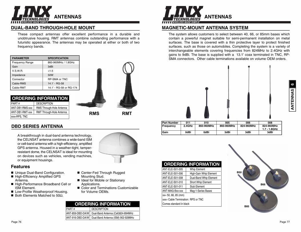
Page 77Page 76
WIRELESS MADE SIMPLE WIRELESS MADE SIMPLE
ANTENNAS
DUAL-BAND THROUGH-HOLE MOUNT These compact antennas offer excellent performance in a durable andunobtrusive housing. RMT antennas combine outstanding performance with afuturistic appearance. The antennas may be operated at either or both of twofrequency bands.
PART # DESCRIPTIONANT-DB1-RMS-xxx RMS Through-Hole AntennaANT-DB1-RMT-xxx RMT Through-Hole Antennaxxx=RPS, TNC
ORDERING INFORMATION
A breakthrough in dual-band antenna technology,the CELNSAT antenna combines a wide-band ISMor cell-band antenna with a high-efficiency, amplifiedGPS antenna. Housed in a weather-tight, tamper-resistant dome, the CELNSAT is ideal for mountingon devices such as vehicles, vending machines,or equipment housings.
DBD SERIES ANTENNA
Unique Dual-Band Configuration.High-Efficiency Amplified GPS Antenna.High-Performance Broadband Cell or ISM Element.Low-Profile Weatherproof Housing.Both Elements Matched to 50Ω.
Center-Fed Through Rugged Mounting Stud.Ideal for Mobile or Stationary Applications.Color and Terminations Customizablefor Volume OEMs.
Features
RMS RMT
ANTENNAS
ORDERING INFORMATION
MAGNETIC-MOUNT ANTENNA SYSTEMThe system allows customers to select between 40, 66, or 85mm bases whichcontain a powerful magnet suitable for semi-permanent installation on metalsurfaces. The base is covered with a thin protective layer to protect finishedsurfaces. such as those on automobiles. Completing the system is a variety ofinterchangeable elements covering frequencies from 824MHz to 2.4GHz withgains to 9dBi. The base is supplied with a 13.1' coax terminated in TNC, RP-SMA connectors. Other cable terminations available on volume OEM orders.
B50
B66
B85
ANT-ELE-S01-005 Whip ElementANT-ELE-S01-006 High-Gain Whip ElementANT-ELE-S01-008 Dual-Band Whip ElementANT-ELE-S01-010 Short Whip ElementANT-ELE-S01-011 Stub ElementANT-MAG-Bxx-xxx Mag-1-Series Basesxx= 50, 66, 85 (mm)xxx= Cable Termination: RPS or TNCComes standard in black
Part Number 011 010 005 006 008Frequency 2.4GHz 860-960MHz 860-960MHz 824-960MHz 824-960MHz
1.7 - 1.8GHzGain 0dBi 0dBi 3dBi 3dBi 3dBi
PART # DESCRIPTIONANT-859-DBD-DA/W Dual-Band Antenna (Cell)824-894MHzANT-916-DBD-DA/W Dual-Band Antenna (ISM) 902-928MHz
ORDERING INFORMATION
PARAMETER SPECIFICATION
Frequency Range 860-960MHz / 1.8GHz
Gain 3dBi
V.S.W.R. <1.5
Impedance 50W
Connector RP-SMA or TNC
Cable-RMS 14.1' - RG-58
Cable-RMT 14.1' - RG-58 or RG-174
AN
TE
NN
AS
6

Page 79Page 78
WIRELESS MADE SIMPLE WIRELESS MADE SIMPLE
Antenna Factor “Corner”-style antennasfeature a wide >70MHz bandwidth,25dB front-to-back ratio, high gain, and a wide beamwidth. These ruggedantennas are constructed to withstandthe stress of long-term use and aredesigned for 50-ohm system matcheswith a maximum input of 100W.
*NOTE* Use of these antennas mayresult in TX and RX emission levels inexcess of legal limits.
CORNER ANTENNAS
PARAMETER SPECIFICATION
Model ANT-916-CN-N ANT-2.4-CN-N
Center Frequency 916MHz 2442MHz
Frequency Range 881-951MHz 2400-2483MHz
Bandwidth 70MHz 83MHz
Gain 10.2dB 10.5dB
Horizontal Beamwidth 50° 54°
Weight 2.6 lbs. 1.75 lbs.
VSWR <1.5
F/B Ratio >25dB
Polarization Vertical
Impedance 50ΩMax. Power 100W
Cable RG-8/U
Connector N-Style (other connectors available for volume applications)
Wind Velocity 60 m/s
PART # DESCRIPTION ANT-916-CN-N 916MHz Corner AntennaANT-2.4-CN-N 2.4GHz Corner Antenna
ORDERING INFORMATION
SPECIALTYANTENNAS
The Antenna Factor division of Linxoffers Yagi antennas in models coveringfrequencies from 400MHz to 2.4GHz.The antennas are designed for long-distance directional communication andcan greatly enhance the performance ofRF links. Made of stainless steel andfeaturing sturdy mast mounts, theserugged antennas are constructed towithstand the stress of long-term use.All antennas are designed for 50-ohmsystem matches with maximum inputsof 100W.
*NOTE* Use of these antennas mayresult in TX and RX emission levels inexcess of legal limits.
PARAMETER SPECIFICATION
Model ANT-2.4-YG6-N ANT-2.4-YG12-N ANT-916-YG5-N ANT-418-YG5-N
Center Frequency 2442MHz 2442MHz 916MHz 418MHz
Frequency Range 2400-2483MHz 2400-2483MHz 881-951MHz 397-439MHz
Bandwidth 83MHz 83MHz 70MHz 42MHz
Gain 9.5dBi 12dBi 9dBi 10dBi
Elements 6 12 5 5
Weight 1.4 lbs. 1.32 lbs. 1.5 lbs. 2 lbs.
Beamwidth 50° 36° 54° 40°
F/B Ratio 18dB 18dB 14dB 18dB
Impedance 50ΩMax. Power 100W
VSWR <1.5
Polarization Vertical or Horizontal
Connector N-Style (other connectors available for volume applications)
Element Material Stainless Steel
Wind Velocity 60 m/s
YAGI ANTENNAS
PART # DESCRIPTION ANT-2.4-YG6-N 2.4GHz 6-Element Yagi AntennaANT-2.4-YG12-N 2.4GHz 12-Element Yagi AntennaANT-916-YG5-N 916MHz 5-Element Yagi AntennaANT-418-YG5-N 418MHz 5-Element Yagi Antenna
ORDERING INFORMATION
SPECIALTYANTENNAS
AN
TE
NN
AS
6

Page 81Page 80
WIRELESS MADE SIMPLE
VISITwww.ConnectorCity.com
for a variety of additionalconnector options
A Division of Linx Technologies
ANTENNA COVERS
PART # DESCRIPTIONANT-SKN-V1-*** SKN-Antenna Cover***= 1.5, 3.15, 4.25 inches
ORDERING INFORMATION
These low-cost sleeves give the externalruggedness and cosmetic appeal of expensivewhip antennas but are hollow to cover the low-cost internal element of a user’s choosing, suchas a wire, rod, or flexible shaft. The sleeve isdesigned to allow a wide range of mountingoptions in metal or plastic housings of variousthicknesses. Ant-skins can also reduce your partsinventory since a wide range of frequency lengthscan be accommodated by a single sleeve.
Features Recesses provided to accommodate 6 different thicknesses
of case materials by simply “pulling” the ant-skin through thecase until it is in the correct position.
Generous cavity to accommodate many different elementsincluding flexible cable, wire, or rod.
Squared base for permanent spin-proof mounting option. Cost-effective. Gives cosmetically attractive, professional appearance.
The multi-purpose base allows mounting in a hole, clamp, or molded-slot configuration.
Through-Hole Mounting
0.375" 0.325" 0.275"
Hook basethrough hole
Rock & rotate to step down to correct position
When correct level for materialis reached, center ant-skin
Molded-slotClamp
ANT-SKINS ANTENNA COVERS
BEFORE AFTER

Page 83Page 82
WIRELESS MADE SIMPLE
13.47(.525")
3.94(.153")
1.27 Dia.(.050") 5.08
(.198")
7 SQ.(.273")
5.08(.198")
4–1.02 SQ.(.040")
13.8(.538")
10.3(.401")
15.1(.589")
11.6(.452")
5.08(.198")
7 SQ.(.273")
5.08(.198")
4–1.02 SQ.(.040")
1.27 Dia.(.050")
3.94(.153")
12.00(.468")
3.94(.153")
1.27 Dia.(.050") 5.08
(.198")
7 SQ.(.273")
5.08(.198")
4–1.02 SQ.(.040")
CONREVSMA001
CONREVSMA002
CONREVSMA008
VERTICAL PCB MOUNT
RIGHT-ANGLE PCB MOUNT
VERTICAL PCB MOUNT - LONG
CONNECTORSThe Final Link to Ultimate RF Performance!
CONNECTORSPART# DESCRIPTION PG.CONREVSMA001 Straight Jack for PC Board 83CONREVSMA002 Right-Angle Jack for PC Board 83CONREVSMA008 Vertical PCB Mount - Long 83CONREVSMA003.031 PCB Horizontal Edge-Mount 84CONREVSMA003.062 PCB Horizontal Edge-Mount 84CONREVSMA006.031 Multi-Mount Horizontal PCB 84CONREVSMA006.062 Multi-Mount Horizontal PCB 84CONREVSMA004 Front-Mount Bulkhead Receptacle 85CONREVSMA004SS Front-Mount Bulkhead Receptacle - Stainless Steel 85CONREVSMA005 Bulkhead Crimp Jack - Captive Contact 85CONREVSMA005-C08.5 Bulkhead Crimp Jack w/8.5" RG-174 Coax 85CONREVSMA005-Cxx.xx Bulkhead Crimp Jack w/Custom RG-174 Coax 85CONREVSMA007 Cable-End Female for RG-174 86CONREVSMA009 PCB Edge-Mount Right-Angle 86
CONNECTORS 7
Linx offers a wide variety of cost-effective PCB and bulkhead RP-SMAconnectors. The high-quality connectors featured in this guide are designed tomate with Linx connectorized antennas. Linx offers many additional styles forhigh-volume OEM use through our Connector City division. Visitwww.connectorcity.com for full details. C
ON
NE
CT
OR
S
7

Page 85Page 84
WIRELESS MADE SIMPLE WIRELESS MADE SIMPLE
6.5(.254")
3.2 (.125") MAX. PANEL
11.4 (.446")
16.3 (.636")
24.5 (.955")
(AFTER ASSEMBLY)
RECOMMENDEDMOUNTING HOLE
27.2 (1.061")
6.6(.256")
RECOMMENDED CABLE STRIPPING DIMENSIONS
3.3(.128")
∅6.5(.254")
6(.234")
9.5(.371")
8 (5/16") HEX6.35 (1/4")HEX
RG-174 Cable
RECOMMENDEDMOUNTING HOLE
∅6.5(.254")
6(.234")
5.6(.218")
∅0.95(.037")
∅1.27(.050")
7.1(.277")
17.3(.675")
3.2 MAX PANEL(.125")
8 (5/16") HEX
SOLDER CUP
CONREVSMA004
CONREVSMA005
FRONT-MOUNT BULKHEAD RECEPTACLE
CABLE END - MALE FOR RG-174
PRE-ASSEMBLED MALE BULKHEAD-WITH RG-174
8.5"RG-174
Heat ShrinkStrain Relief
CONREVSMA005
CONREVSMA005-C08.5 (8.5" STANDARD)
CONREVSMA005-Cxx.xx (xx.xx=CUSTOM LENGTH, 1K MIN. ORDER)
CONNECTORS
11.4(0.445")
6.3(0.242")
3.9(0.152")
1.02(0.04")
1.2(0.047")
1.02(0.04")
1.27 terminal(0.05")
1/4-36THREADS
* see below
0.914 (0.036") for 0.031 model1.676 (0.066") for 0.062 model
*
4(0.16")
6.1(0.24")
20.4(0.786")
9.6(0.375")
4.5(0.175")
3.9(0.152")
1.02(0.04")
1.2(0.050")
1.2(0.050")
1.02(0.04")
1.27 terminal(.05")
7.9(0.31")
4(0.16")
6.1(0.24")1/4-36
THREADS
8 (5/16") HEX
RECOMMENDEDMOUNTING HOLE
∅6.5(0.254")
∅8.3(0.325")
∅5.8(0.225")
8.3(0 .33")
6(0.234")
0.914 (0.036") for 0.031 model1.676 (0.066") for 0.062 model
*
* see below
CONREVSMA003.031 for 0.031 Board ThicknessCONREVSMA003.062 for 0.062 Board Thickness
CONREVSMA006.031 for 0.031 Board ThicknessCONREVSMA006.062 for 0.062 Board Thickness
yy
yClamps intomolded case
Use of nutoptional
yy
Clamps intomolded case
Flange hideshole
yyyy
yyyy
Serves as rear flange
Plastic/MetalCase
Mounting Options
HORIZONTAL PCB EDGE-MOUNT
MULTI-MOUNT HORIZONTAL PCB
CONNECTORS
CO
NN
EC
TO
RS
7

Page 87Page 86
WIRELESS MADE SIMPLE
ADDITIONAL SERVICES 8
An engineer will generally choose most components based on technical issuesof function and application. RF products are unusual in that they involve not onlysuch technical issues but issues of legality as well. Many manufacturers haveavoided incorporating RF into their products as a result of uncertainty and evenfear of such matters.
In order to address these concerns and simplify each customer’s design cycle,Linx has attempted to identify any step in the RF implementation process thatmay cause delay or frustration. We have then tailored a service to simplify thatstep. While such services are unusual for a high-volume componentmanufacturer, they are all a part of the Linx commitment to “Making WirelessSimple”.
6.5(.254")
8.4 (.328")
16.9 (.660")
1.2(.047")
RECOMMENDED CABLE STRIPPING DIMENSIONS
2.2(.0861")
9.5(.371")
8 (5/16") HEX
6.3(.246")
RG-174 Cable
0.6(.023")
CONREVSMA007
CONREVSMA009
CABLE END FOR RG-174 - FEMALE
20.4(.786")
4.5(.175")
3.9(.152")
1.02(.04")
1.2(.050")
1.2(.050")
1.02(.04")
1.27 terminal(.05")
1.63(.064")
7.93(.31")
4.06(.158")7.93
(.309")
7.70(.300")
1/4-36THREADS
∅8.3(.325")
∅6.0(.225")
8.3(.325")
6.4(0.25")
7.0(0.275")
7.0(0.275")
7.0(0.275")
RPSMA PCB EDGE-MOUNT RIGHT-ANGLE JACKRECEPTACLE W/FLANGE
CONNECTORS

Page 89Page 88
WIRELESS MADE SIMPLE WIRELESS MADE SIMPLE
INTERNET SITEIf you have questions regardingany Linx product, and haveinternet access, make
www.linxtechnologies.com
your first stop. Our website isorganized in an intuitive format togive you the answers you need inrecord time. Day or night, the Linxwebsite gives you instant accessto the latest information regardingthe products and services of Linx.It's all here: manual and softwareupdates, application notes, FCCinformation and much more. Besure to visit soon!
IMPLEMENTATION ASSISTANCEWhile Linx does not undertake OEM designprojects in most instances, our engineers havebroad experience in almost every area of designand manufacturing. Linx is pleased to offer ourcustomers the benefit of that experience as itpertains to the integration of Linx RF productsinto a product design.
EDUCATIONAt Linx we believe that our best customer is aninformed customer. That is why our comprehensivemanuals are supported by a growing library ofinformative application notes. Linx application notesare designed to provide guidance on the effectiveapplication of its products across a broad range ofapplications. Many different topics are discussed ina fashion inappropriate for the device data sheet,from matters to consider before embarking on a design to complete overviews oflegal and technical issues affecting wireless products. Backed by the assistanceof experienced support personnel, each customer has an opportunity to learnabout our products and the basic principles of RF whereby they work. Applicationnotes may be downloaded from www.linxtechnologies.com or obtained bycontacting the Linx literature department.
ANTENNA DESIGN ASSISTANCELinx offers a complete variety of standard antenna stylesthat will meet the needs of most users’ applications.Occasionally a design will call for a custom antenna tomeet physical or cosmetic constraints. Since the designof application-specific antennas calls for experience andequipment outside the scope of many of our customers,Linx offers antenna design services. These servicesrange from assistance evaluation of a customer’santenna configuration to actual antenna design. One ofour most popular design specialties is small printedantennas that are often incorporated directly on a PCBto reduce cost and eliminate a visible antenna.
FCC PRESCREEN SERVICESThe most difficult obstacle to overcomewhen bringing an RF-based product tomarket, aside from the design itself, isthe approval process. To ensure acustomer the best opportunity to passFCC testing, Linx offers unique low-costpre-compliance testing services. Usingour state-of-the-art Hewlett PackardEMC-compliancy test system, a productis screened just as it will be duringactual FCC testing. In addition to thisscreen, the actual design is evaluatedby a Linx engineer to ensure that it isboth legal and technically optimized. A prescreen report is then generatedsummarizing our findings and recommendations. This report, along withadditional documentation, will ease your preparations for final approval testing.
OEM MODIFICATIONSAs a rule Linx does not undertake the design ormanufacture of customer-specific products; however, manyproducts can be modified for high-volume applications. OurOEM product lines are especially suited to suchmodifications. Company logos, custom colors andnomenclature are all ways that Linx products can beadapted to meet the needs of an individual customer.Custom antennas, cables, and connectors can also beprovided through Linx’s Antenna Factor and Connector Citydivisions.
ADDITIONAL SERVICES ADDITIONAL SERVICES
AD
DIT
ION
AL
SE
RV
ICE
S
8

Page 91
Linx application notes are designed to provideguidance on the effective application of itsproducts across a broad range of applications.Many different topics are discussed in a fashioninappropriate for the device data sheet, frommatters to consider before embarking on a designto complete overviews of legal and technicalissues affecting wireless products. This library isever expanding and your suggestions for topics ofinterest are always welcomed. Please check theLinx internet site for additional topics that mayhave become available since the date of this publication. Application notes maybe downloaded from www.linxtechnologies.com or obtained by contacting theLinx literature department.
APPLICATIONS LITERATURE 9
APPLICATION NOTESNumber Description#00100 RF 101: Information for the RF Challenged#00125 Considerations for Operation Within 260-470MHz Band#00126 Considerations for Operation Within 902-928MHz Band#00130 Modulation Techniques for Low-Cost RF Data Links#00134 Using the LC-Series to Create a Simple Telemetry Link#00140 The FCC Road: Part 15 from Concept to Approval#00150 Use and Design of T-Attenuation Pads#00155 Serial Load Techniques for HP Series 3 RF Modules#00160 Considerations for Sending Data with the HP Series#00232 General Considerations for Sending Data With the LC Series#00500 Antennas: Design, Application, Performance

Page 92
WIRELESS MADE SIMPLE
Page 93
WIRELESS MADE SIMPLE
HOURS
Excepting holidays, representatives are available 8:00 AM to 4:00 PM PST to assist you with yourorder, technical, or account questions.
PAYMENT TERMS
Evaluation kits and orders for less than 1,000 pcs. require prepayment by check or credit card.Linx Technologies is pleased to extend NET 30 terms to approved accounts with adequate creditstanding. A completed credit application, accompanied by a single order of $1,500 or more, isrequired to establish an account. Please allow two weeks for credit to be established.
QUANTITY DISCOUNTS
Linx will extend quantity pricing discounts based on the amount of product purchased in a six-month period with up to four product release dates. In the event of rescheduling or partialcancellations, Linx reserves the right to adjust the invoice amounts to reflect the actual productaccepted.
DELINQUENT ACCOUNTS
Any account more than 20 days in arrears will be placed on credit hold, and your accountingdepartment contacted. A 1.5% per month (18% annual) finance charge will be added to delinquentamounts. Billing is a courtesy and we ask you to render payment promptly.
ORDER CANCELLATIONS
An order may be cancelled at any time. If the cancellation affects the quantity discounts extendedfor a blanket order the customer will be billed retroactively for the difference between the quantitiesordered and quantities taken. If the order is in transit the customer will be charged for freight. Noother penalties are imposed unless otherwise noted in writing.
EVALUATION KIT PURCHASE REQUIREMENT
Linx requires the purchase of an evaluation kit prior to the sale of individual modules to anycustomer. This policy insures that each customer has the tools necessary to fairly evaluate ourproducts and legally apply them. In addition, a benchmark platform among all our customersallows our engineers the best chance to assist should application difficulties arise.
SPONSORSHIPS/DONATIONS
The primary market focus of Linx Technologies is volume OEM manufacturers. We recognize,however, that our products have broad application outside this target market. Each year Linxreceives many requests for donations from charitable, scientific, or educational institutions. WhileLinx finds it appropriate to honor only a small percentage of these requests, each request is fairlyconsidered in light of its scope and merit. If you have such a request please state in writing theinstitution you represent, the nature of your project, its merit and the value to Linx of participation.Address your correspondence to: Linx Technologies, Inc. Attention: Director of Marketing, 575SE Ashley Pl., Grants Pass, OR 97526.
LICENSING REQUIREMENTS
Every module is designed with FCC Part-15 compliance in mind; however, it is the responsibilityof each user to verify its appropriateness for each individual application and to obtain certificationof the completed product as needed.
RETURNS
Returns must be accompanied by a valid Return Merchandise Authorization Number (RMA#),which may be obtained by calling our customer service department at (541) 471-6256. Productsnot bearing an RMA# will be returned at shipper’s expense. Returns will be accepted only underthe following conditions:1. 15% Restocking. Accounts may return product subject to a 15% restocking charge
provided it is in new condition and was invoiced within the past four months. Value ofthe product will be the price paid according to the original invoice and will not includeshipping charges.
2. 2 for 1 balancing. The returned components will be accepted without restocking and fullcredit issued provided:A) The components are in as-new condition and were invoiced within the past fourmonths and;B) The returned merchandise is accompanied by an order equivalent to twice the valueof the merchandise being returned. Value of the product will be the price paid accordingto the original invoice and will not include shipping charges.
CHANGES
Linx realizes customers’ needs change rapidly. We attempt to accommodate change requirementson a case-by-case basis.
LEAD TIMES
Linx attempts to maintain a shelf stock to buffer urgent small-quantity requirements; however,due to the popularity of the product and rapid stock fluctuations it is best to allow 8-10 weeksfor volume deliveries. Actual lead times will be quoted at the time of sale. More urgent requirementsare accommodated whenever possible.
WARRANTY OF FITNESS
Linx Technologies is continually striving to improve the quality and function of its products; forthis reason, we reserve the right to change, in whole or in part, prices, product specifications,products offered, terms and conditions of sale, and policies without prior notice.The informationcontained in this Price List is believed to be accurate as of the time of publication. Specificationsare based on representative lot samples. Values may vary from lot to lot and are not guaranteed.Linx Technologies makes no guarantee, warranty, or representation regarding the suitability ofany product for use in a specific application. None of these devices is intended for use inapplications of a critical nature where the safety of life or property is at risk. The user assumesfull liability for the use of product in such applications. Under no conditions will Linx Technologiesbe responsible for losses arising from the use or failure of the device in any application, orfailure to meet delivery requirements, other than the repair, replacement, or refund limited tothe original product purchase price. Some devices described in this publication may be patentedor proprietary. Under no circumstances shall any user be conveyed any license or right to theuse or ownership of these patents. No other warranties, expressed or implied, or statutory,including warranties of fitness for a particular purpose, apply. Linx Technologies shall not beliable for incidental or consequential damage or commercial loss, or any other loss or damage.
AP
PL
ICA
TIO
NS
LIT
ER
AT
UR
E
9
Page 94
Linx Technologies, Inc.575 S.E. Ashley PlaceGrants Pass, Or 97526
PHONE: (541) 471-6256FAX: (541) 471-6251http://www.linxtechnologies.com
U.S. CORPORATE HEADQUARTERS:
WIRELESS MADE SIMPLE
Linx Technologies is continually striving to improve the quality and function of its products; forthis reason, we reserve the right to make changes without notice. The information contained inthis Data Sheet is believed to be accurate as of the time of publication. Specifications are basedon representative lot samples. Values may vary from lot to lot and are not guaranteed. "Typical"parameters can and do vary over lots and application. Linx Technologies makes no guarantee,warranty, or representation regarding the suitability of any product for use in a specificapplication. It is the customer’s responsibility to verify the suitability of the part for the intendedapplication. None of these devices is intended for use in applications of a critical nature wherethe safety of life or property is at risk. Should the user purchase or utilize Linx products for suchunintended or unauthorized application, the user assumes full liability for the use of product insuch applications and shall indemnify and hold Linx, and its officers, employees, subsidiaries,affiliates, distributors, and representatives harmless against all claims, costs, damages,expenses, and attorney fees, even if such a claim alleges that Linx was negligent regarding thedesign or manufacture of the part. Under no conditions will Linx Technologies be responsiblefor losses arising from the use or failure of the device in any application, other than the repair,replacement, or refund limited to the original product purchase price. Devices described in thispublication may contain proprietary, patented, or copyrighted techniques, components ormaterials. Under no circumstances shall any user be conveyed any license or right to the useor ownership of such items. © 2003 by Linx Technologies, Inc. The stylized Linx logo, Linx, and “Wireless Made Simple”
are the trademarks of Linx Technologies, Inc. Printed in U.S.A.
Disclaimer