Wireless Local Area Networks - Technische Universität Ilmenau · 2017-11-05 · Wireless Local...
39
Wireless Local Area Networks Experiments for Bachelor Students of Mobile Communication Networks Course http://www.tu-ilmenau.de/iks/lehre/bachelor-studiengaenge/?event_id=11 Dr.-Ing. Florian Evers & Prof. Dr.-Ing. habil. Andreas Mitschele-Thiel Integrated Communication Systems Faculty of Computer Science and Automation Ilmenau University of Technology
Transcript of Wireless Local Area Networks - Technische Universität Ilmenau · 2017-11-05 · Wireless Local...

Wireless Local Area NetworksExperiments for Bachelor Students of Mobile Communication
Networks Coursehttp://www.tu-ilmenau.de/iks/lehre/bachelor-studiengaenge/?event_id=11
Dr.-Ing. Florian Evers & Prof. Dr.-Ing. habil. Andreas Mitschele-ThielIntegrated Communication SystemsFaculty of Computer Science and AutomationIlmenau University of Technology


Contents
1. Introduction 51.1. Test Set-up . . . . . . . . . . . . . . . . . . . . . . . . . . . . . . . . . . . . . 51.2. Gentoo Linux . . . . . . . . . . . . . . . . . . . . . . . . . . . . . . . . . . . . 5
2. Network Topology 72.1. IP-Addresses . . . . . . . . . . . . . . . . . . . . . . . . . . . . . . . . . . . . 82.2. Netmasks . . . . . . . . . . . . . . . . . . . . . . . . . . . . . . . . . . . . . . 8
3. Homework: Preparation 9
4. Experiments 114.1. Building the Network . . . . . . . . . . . . . . . . . . . . . . . . . . . . . . . 11
4.1.1. Router . . . . . . . . . . . . . . . . . . . . . . . . . . . . . . . . . . . . 114.1.2. Backbone Router . . . . . . . . . . . . . . . . . . . . . . . . . . . . . . 124.1.3. Server . . . . . . . . . . . . . . . . . . . . . . . . . . . . . . . . . . . . 124.1.4. Subnet Router . . . . . . . . . . . . . . . . . . . . . . . . . . . . . . . 124.1.5. Access Points . . . . . . . . . . . . . . . . . . . . . . . . . . . . . . . . 13
4.1.5.1. Access Point 1 . . . . . . . . . . . . . . . . . . . . . . . . . . 134.1.5.2. Access Point 2 . . . . . . . . . . . . . . . . . . . . . . . . . . 13
4.2. Sniffing and Traffic Monitoring . . . . . . . . . . . . . . . . . . . . . . . . . . 154.2.1. Traffic Capturing . . . . . . . . . . . . . . . . . . . . . . . . . . . . . . 154.2.2. Traffic Filtering . . . . . . . . . . . . . . . . . . . . . . . . . . . . . . . 15
4.2.2.1. Display Filters . . . . . . . . . . . . . . . . . . . . . . . . . . 154.2.2.2. Capture Filters . . . . . . . . . . . . . . . . . . . . . . . . . . 16
5. Configure Cisco Aironet 1200 195.1. Web Interface . . . . . . . . . . . . . . . . . . . . . . . . . . . . . . . . . . . . 19
5.1.1. Home . . . . . . . . . . . . . . . . . . . . . . . . . . . . . . . . . . . . 195.1.2. Network . . . . . . . . . . . . . . . . . . . . . . . . . . . . . . . . . . . 205.1.3. Associations . . . . . . . . . . . . . . . . . . . . . . . . . . . . . . . . . 215.1.4. Setup . . . . . . . . . . . . . . . . . . . . . . . . . . . . . . . . . . . . 22
5.2. Configuration . . . . . . . . . . . . . . . . . . . . . . . . . . . . . . . . . . . . 235.2.1. IP and ESSID . . . . . . . . . . . . . . . . . . . . . . . . . . . . . . . 235.2.2. Default Gateway . . . . . . . . . . . . . . . . . . . . . . . . . . . . . . 255.2.3. Radio Channel and Transmit Power . . . . . . . . . . . . . . . . . . . 265.2.4. WEP . . . . . . . . . . . . . . . . . . . . . . . . . . . . . . . . . . . . 27
Abbreviations 29
Contact 33
A. Handouts 35A.1. Handout: Network topology . . . . . . . . . . . . . . . . . . . . . . . . . . . . 35
3

A.2. Handout: IP addresses and netmasks . . . . . . . . . . . . . . . . . . . . . . . 37A.3. Handout: Linux Commands . . . . . . . . . . . . . . . . . . . . . . . . . . . . 39
4
1. Introduction
Wireless technologies are available since decades ago. One of the popular networks is theWireless Local Area Network (WLAN). Main reasons for the popularity of WLAN arethe always reduced cost of hardware and the ability of WLAN to be quick installed andconfigured in addition to the services that can be offered using such networks. The fact thatWLAN is only suitable for indoor environments has resulted in deploying these networks incompanies, airports, hospitals, etc. Thus, it is useful to provide students with knowledge onhow to build and configure a WLAN, which is the purpose of these experiments.The rest of this document is structured as follows: chapter 2 provides the network topologyof the experiment. In chapter 3 some tasks are given, which should be done before theexperiment. Chapter 4 goes through the experiments that should be done step by step. Howto configure the access points, used in these experiments, is provided in chapter 5.
1.1. Test Set-up
The test set-up consists of one mobile node, two access points and four computers connectedto a Keyboard–Video–Mouse (KVM) switch. With the help of the KVM switch, you canuse one keyboard, mouse and monitor for all four computers. All network cables requiredfor the experiment are already connected.
Table 1.1.: KVM layoutPort Computer
1 Server2 Backbone Router3 Router4 Subnet Router
1.2. Gentoo Linux
The operating system on all computers and the mobile node is Gentoo Linux. To configurethe network you will work on the Unix-Shell. Each entered command will be saved in acommand history and can be recalled with the help of the arrow up and down keys on thekeyboard. If you want to abort a running command, press “CTRL-C”.
5


2. Network Topology
Figure 2.1 shows the network topology of the experiments. The network is hierarchicallystructured and can be assumed as a simple structure of a part of the Internet. As the figureshows, the network consists of a server, a backbone router, a router, a subnet router andtwo access points. The Internet Protocol (IP) addresses and netmasks of the network nodesaccording the figure. On all computers the network interface eth0 is used for the Internetconnection, but is not used in the experiment.
Access Point 1
Mobile Node
Access Point 2Subnet Router
Router
Backbone Router
Server
eth1
eth2eth1
eth3eth1
eth2
eth1
eth2
Server
10.16.0.0/12 10.32.0.0/12
10.33.0.0/16 10.34.0.0/16
10.33.1.0/24
eth1: 10.16.0.2/30
Backbone Router
eth1: 10.16.0.1/30
eth2: 10.32.0.1/30
Router
eth1: 10.33.0.1/30
eth2: 10.34.0.1/16
eth3: 10.32.0.2/30
Subnet Router
eth1: 10.33.0.2/30
eth2: 10.33.1.1/24
Access Point 1
IP: 10.33.1.2/24
Access Point 2
IP: 10.34.0.2/16
Mobile Node
IP 1: 10.33.1.3/24
IP 2: DHCP
Figure 2.1.: Network topology of the experiments
Access point 1 works on channel 5, transmits with 20mW power and has Extended ServiceSet Identifier (ESSID) set to IKS WLAN AP1, while access point 2 operates on channel11, sends with 5mW and has ESSID set to IKS WLAN AP2. The target is to configurethe network provided in the figure 2.1, so that the mobile node can communicate with theserver, which represents the Internet as it runs a web server.
7

2.1. IP-Addresses
The IP addresses used in this experiment are free to use for private networks. The InternetAssigned Numbers Authority (IANA) defined 3 address ranges for private networks:
Table 2.1.: IP addresses for private networks [ipa11]address range CIDR # addresses10.0.0.0 to 10.255.255.255 10.0.0.0/8 224 = 16.777.216172.16.0.0 to 172.31.255.255 172.16.0.0/12 220 = 1.048.576192.168.0.0 to 192.168.255.255 192.168.0.0/16 216 = 65.536
In this practical course, IP addresses of the range 10.0.0.0/8 are used.
2.2. Netmasks
A netmask is a bitmask, for the network protcol IPv4, that describes how many bits fromthe beginning of the IP address are used for the netprefix. A netmask has a length of 32 bit.All bits of the network part are set to 1, and all remaining bits of the host part are set to 0.A short notation of the netmask is the Classless Inter-Domain Routing (CIDR) notation,where the number of continious 1 bits from the left is counted.
Table 2.2.: netmask examples [net11]CIDR netmask binary netmask # addresses/8 255.0.0.0 11111111 00000000 00000000 00000000 16777214/12 255.240.0.0 11111111 11110000 00000000 00000000 1048574/16 255.255.0.0 11111111 11111111 00000000 00000000 65534/20 255.255.240.0 11111111 11111111 11110000 00000000 4094/24 255.255.255.0 11111111 11111111 11111111 00000000 254/30 255.255.255.252 11111111 11111111 11111111 11111100 2
8
3. Homework: Preparation
Router Server
192.169.0.0/8
Computer
192.168.0.0/24eth1 eth1 eth2 eth1
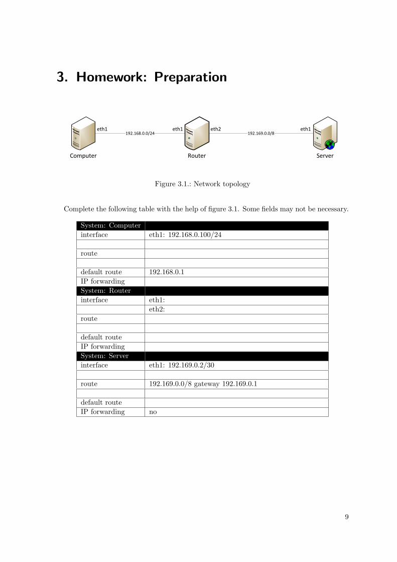
Figure 3.1.: Network topology
Complete the following table with the help of figure 3.1. Some fields may not be necessary.
System: Computerinterface eth1: 192.168.0.100/24
route
default route 192.168.0.1IP forwardingSystem: Routerinterface eth1:
eth2:route
default routeIP forwardingSystem: Serverinterface eth1: 192.169.0.2/30
route 192.169.0.0/8 gateway 192.169.0.1
default routeIP forwarding no
9
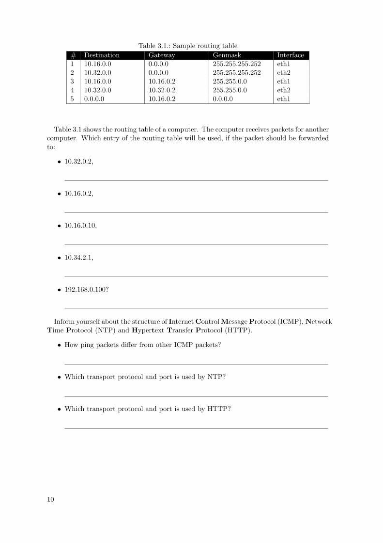
Table 3.1.: Sample routing table# Destination Gateway Genmask Interface1 10.16.0.0 0.0.0.0 255.255.255.252 eth12 10.32.0.0 0.0.0.0 255.255.255.252 eth23 10.16.0.0 10.16.0.2 255.255.0.0 eth14 10.32.0.0 10.32.0.2 255.255.0.0 eth25 0.0.0.0 10.16.0.2 0.0.0.0 eth1
Table 3.1 shows the routing table of a computer. The computer receives packets for anothercomputer. Which entry of the routing table will be used, if the packet should be forwardedto:
• 10.32.0.2,
• 10.16.0.2,
• 10.16.0.10,
• 10.34.2.1,
• 192.168.0.100?
Inform yourself about the structure of Internet Control Message Protocol (ICMP), NetworkTime Protocol (NTP) and Hypertext Transfer Protocol (HTTP).
• How ping packets differ from other ICMP packets?
• Which transport protocol and port is used by NTP?
• Which transport protocol and port is used by HTTP?
10
4. Experiments
The interfaces in all network nodes are not configured yet. First you have to configure theinterfaces and assign the correct IP adresses. Afterwards you have to construct suitablerouting tables in the network nodes, so that each node can reach all nodes connected directlyto it. The next step is to activate IP forwarding, so each node can reach all other nodes inthe network. IP forwarding enables the packet transfer between all network interfaces of onecomputer.The following steps help you. Remember, all steps are just explained once, the procedure forthe other computers is analog.
4.1. Building the Network
Turn on all computers and the mobile node.
• username: praktikum
• password: praktikum
4.1.1. Router
i. Type “ifconfig -a”. How many interfaces can you see? Which interfaces are alreadyactive?
ii. The network interface eth1 is not configured. Use “ifconfig eth1 10.33.0.1/30”to configure the interface for the transit network.
iii. The interface eth2 is already configured, because the router runs a Dynamic HostConfiguration Protocol (DHCP) server on it. Configure interface eth3 according toeth1.
iv. Type “ifconfig”. What do you see now?
v. Type “route add default gw 10.32.0.1”. This command adds interface eth2 ofthe backbone router as default gateway for the router. If the router does not knowwhere to forward a packet, it will send the packet to the defined gateway.
vi. Type “route add -net 10.33.0.0/16 gw 10.33.0.2”, to add a route from eth1 tothe interface of the subnet router. Notice that the server is directly connected to therouter.
vii. If you want to check, whether the routing table is built correctly, type “route -n”.Interpret what you see.
11

viii. Type “nano /proc/sys/net/ipv4/ip forward”. To enable IP forwarding, replace 0with 1, save (CTRL-O) the file and exit (CTRL-X) nano.
4.1.2. Backbone Router
i. Configure the network interfaces to the following addresses: “10.16.0.1/30” (eth1)and “10.32.0.1/30” (eth2).
ii. Add a route from the backbone router to the server and the router.
iii. If a default gateway is necessary, add one.
iv. Check, whether the routing table is built correctly.
v. Type “ping 10.32.0.2 -c 4”. If everything is configured correct, you should obtainfour replies from the interface.
vi. Don’t forget to enable IP forwarding.
4.1.3. Server
i. The network interface eth1 is not yet configured. Configure it to “10.16.0.2/30”.
ii. Add a route, from eth1 to the backbone router.
iii. Add the backbone router as default gateway for the server.
iv. Is there a need of step ii and step iii, or is one of them enough? In case one is enough,which one would you choose? Discuss by looking at the routing table.
v. Ping the backbone router (10.16.0.1). If everything is configured correctly, you shouldobtain a reply from the interface.
vi. Is IP forwarding necessary for the server? Why or why not?
4.1.4. Subnet Router
i. Configure the network interfaces and create corresponding routing tables.
ii. If a error message appears, explain it. How to fix the error?
iii. Test the network with the help of the ping command. Especially ping the server(10.16.0.2).
iv. Enable IP forwarding if necessary.
12

4.1.5. Access Points
The next step is to configure the access points. If you turn on the access points for the firsttime, the default settings are loaded. If no DHCP server is connected to the access point,the IP address is set to 10.0.0.1/24. On default ESSID is set to “tsunami” and the accesspoint transmits on channel 7. Use the mobile node to configure the access points. Configurethem one after another, to avoid confusion. Which access point is connected to a DHCPserver?
4.1.5.1. Access Point 1
i. Change the IP address of the interface wlan0 to the following address “10.0.0.2/24”.
ii. Take care that only one access point 1 is powered.
iii. With the command “iwconfig wlan0 essid tsunami” you can connect the mobilenode to the access point.
iv. Type “iwconfig” and check if you are connected.
v. Send ping packets to the access point.
vi. Type “konqueror”, to open the webbrowser, and access “http://10.0.0.1”.
vii. You have to configure the IP address, network mask, default gateway, ESSID, workingchannel and sending power of the access point. Reflect about the order of the changes.Maybe you have to reconnect to the accesspoint after some changes. Read chapter 5at page 19 if you need some help for configuration.
viii. Configure the interface wlan0 to the following IP address: “10.33.1.3/24” and addaccess point 1 as default gateway.
ix. Connect the mobile node to the access point “IKS WLAN AP1”.
x. If everything is configured correct, you should be able to ping the server.
4.1.5.2. Access Point 2
i. At first plug in access point 2.
ii. Deactivate the interface wlan0 to delete the IP address and the default gateway withthe help of “ifconfig wlan0 down”.
iii. Type “ifconfig wlan0 up” to reactivate the interface.
iv. Type “iwlist scan wlan0” to scan for visible accesspoints and analyze the output.
v. Connect the mobile node to the access point “tsunami”
vi. Check if you are connected.
vii. Type “dhcpcd wlan0”. Now you get your IP address, netmask and default gatewayfrom the DHCP server.
viii. Open Konqueror and access “http://10.34.0.2”.
13

ix. You have to configure ESSID, working channel and sending power of the access point.Maybe you have to reconnect to the accesspoint after some changes.
x. Connect the mobile node to the access point “IKS WLAN AP2”.
xi. Scan for visible accesspoints and analyze the output. What has changed?
xii. If everything is configured correct, you should be able to ping the server.
14

4.2. Sniffing and Traffic Monitoring
Packet sniffers are capable to capture network traffic, decoding packet contents and presentingthem in readable way. Sniffers are used to monitor network traffic and debug errors in thenetwork operation. This experiment provides an insight into how to use such sniffers tomonitor, filter and analyze network traffic. The packet sniffer used in this experiment iswireshark (http://www.wireshark.org/).
4.2.1. Traffic Capturing
Start wireshark on the mobile node by typing “wireshark” on the command line. Click on“Capture→Interface”, to open the Capture Interfaces window. This window shows allinterfaces that wireshark has detected. Click on the “Start” button, responsible to yourwireless interface, to start capturing packets.
i. Wait about one minute. Which protocols do you see?
ii. Which IP addresses do you find in the current trace file?
iii. Wireshark provides you with lots of informations about the captured packets. Whichkind of informations can you obtain?
iv. Send ping packets from the mobile node to the server.
v. Monitor the ping packets in wireshark and notice their content and delay.
4.2.2. Traffic Filtering
For effective traffic monitoring, traffic should be filtered, so only traffic matching the filterwill be presented. The next steps should give you an insight into how to create and use trafficfilters.
4.2.2.1. Display Filters
i. Send ping packets from the mobile node to the server.
ii. Create a filter to present only the packets sent by the server to the interface of yourmobile node or reverse (Filter: “ip.addr == 10.16.0.2”). What do you see?
15

iii. You can extend the filter, to show only traffic of a certain protocol. For example, pingpackets are sent, using ICMP. If we are interested in this traffic only, we have to usean adequate filter (Filter: “ip.addr == 10.16.0.2 && icmp”).
iv. Now delete the filter to show all packets. Notice the types of packets you receive. Writefilters to show the traffic of each protocol for itself.
v. Access “http://10.16.0.2” in your browser and repeat step iv.
4.2.2.2. Capture Filters
In contrast to display filters, which capture all packets and present them matching certainrules, capture filters affect the capturing of packets themselves. Only packets matching thegiven filter will be captured. The basic syntax of capture filters in wireshark is the following:
[not] primitive [and|or [not] primitive ...]
16

Table 4.1.: Some primitives available in wireshark [wir11]Command Task[src|dest] host <ip address> This primitive allows you to filter on a host IP address
or name. You can optionally precede the primitivewith the keyword src|dst to specify that you are onlyinterested in source or destination addresses.
ether [src|dst] host <ehost> This primitive allows you to filter on Ethernet hostaddresses. You can optionally include the keywordsrc|dst between the keywords ether and host tospecify that you are only interested in source or des-tination addresses.
gateway host <host> This primitive allows you to filter on packets thatused host as a gateway. That is, where the Ethernetsource or destination was host but neither the sourcenor destination IP address was host.
[tcp|udp] [src|dst] port <port> This primitive allows you to filter on TCP and UDPport numbers. You can optionally precede this prim-itive with the keywords src|dst and tcp|udp whichallow you to specify that you are only interested insource or destination ports and TCP or UDP pack-ets respectively. The keywords tcp|udp must appearbefore src|dst.
less|greater <length> This primitive allows you to filter on packets whoselength was less than or equal to the specified length,or greater than or equal to the specified length, re-spectively.
ether|ip broadcast|multicast This primitive allows you to filter on either Ethernetor IP broadcasts or multicasts.
Table 4.2.: Operators for primitives in wireshark [wir11]Operator Meaning!, not logical NOT-operation&&, and logical AND-operation||, or logical OR-operation& bitwise AND-operation
17
You can access and check the content of packets with the help of the capture filters. Thebasic syntax is:
protocol[<offset in bytes from the beginning of the header>:<number ofbytes>]
Table 4.3.: Examples for filter expressions checking the contents of packets [wir11]Filter Resultip[8] = 1 Filters IP packets, where the byte number 8 (TTL)
equals 1.tcp[0:2] = 22 Filters TCP packets, where the value of the first two
bytes of TCP header (port number) equals 22.
Notice that the “<number of bytes>” in the basic syntax can be 1, 2 or 4. If you do notgive any number, this value will be 1.
If you want to use a capture filter, you have to stop capturing first. Next step is to click“Capture→Interface”. Before you can restart capturing, you have to click “Options” re-sponsible to your wireless interface. Enter your filter behind “Capture Filter:” and press“Start”. Now practice your knowledge about filtering.
i. Access “http://10.16.0.2” in Konqueror.
ii. Write a filter that captures all packets with Time to Live (TTL) greater than 63.
iii. Ping the server to test the filter. What can you see?
iv. Write a filter that captures all HTTP traffic.
v. Test the filter by accessing the server in Konqueror.
vi. Write a filter that captures all NTP traffic sent from the mobile node. Reflect whichprotocol and port is used by NTP.
vii. Write a filter that captures all ICMP packets, but no ping ones. Reflect the structureof the ICMP header.
18

5. Configure Cisco Aironet 1200
5.1. Web Interface
5.1.1. Home
Figure 5.1 shows the “Home” page, that displays the status of the access point. There youcan see informations about the number of radio devices associated, the status of the Ethernetas well as the radio interface and a list of recent events. Also, this page shows informationabout IP and Media Access Control (MAC) addresses of both interfaces.
Figure 5.1.: Summary Status
19

5.1.2. Network
Figure 5.2 shows the “Network” page. It displays the status and statistics for the Ethernetand radio interfaces.
Figure 5.2.: Network Ports
20

5.1.3. Associations
The “Associations” page displays a list of all devices in your WLAN. It lists their systemnames, network roles, and parent-client relationships. Figure 5.3 presents a screenshot of thepage.
Figure 5.3.: Association Table
21

5.1.4. Setup
The “Setup” page is shown in Figure 5.4. It contains links for configure associations, eventlog, services and network ports. Section 5.2 gives you a insight in some of the configurations.
Figure 5.4.: Setup
22

5.2. Configuration
5.2.1. IP and ESSID
Click on the link “Identification” behind “AP Radio: Internal” on the “Setup” page.Here you can configure the IP address, network mask and ESSID of the radio interface.
Figure 5.5.: AP Radio: Internal Identification
23
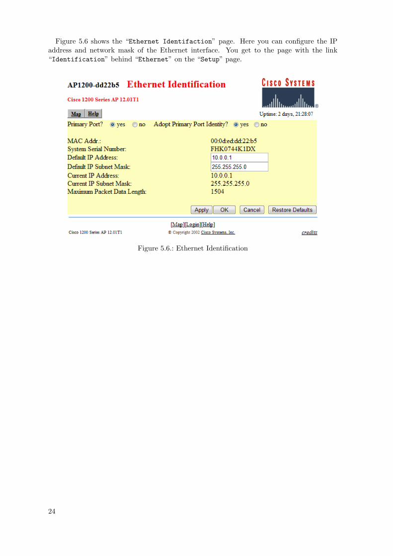
Figure 5.6 shows the “Ethernet Identifaction” page. Here you can configure the IPaddress and network mask of the Ethernet interface. You get to the page with the link“Identification” behind “Ethernet” on the “Setup” page.
Figure 5.6.: Ethernet Identification
24
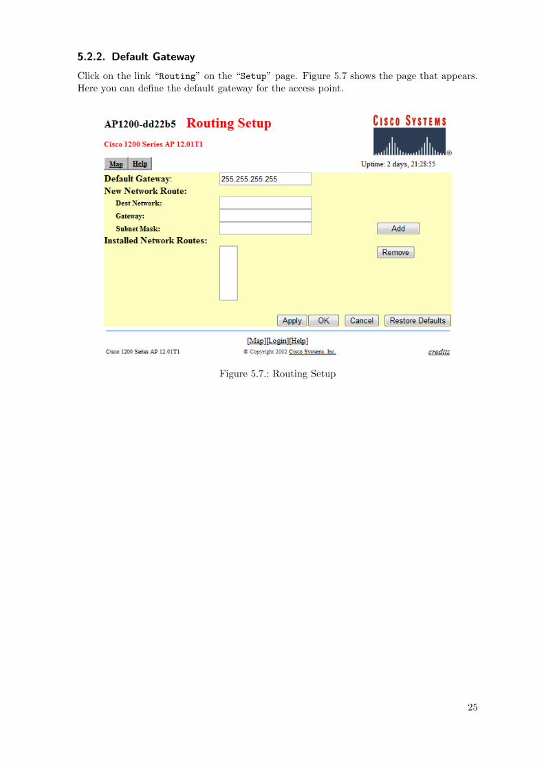
5.2.2. Default Gateway
Click on the link “Routing” on the “Setup” page. Figure 5.7 shows the page that appears.Here you can define the default gateway for the access point.
Figure 5.7.: Routing Setup
25
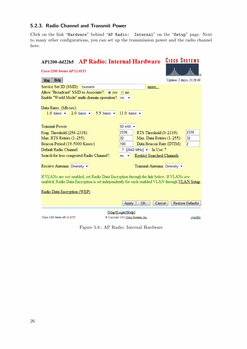
5.2.3. Radio Channel and Transmit Power
Click on the link “Hardware” behind “AP Radio: Internal” on the “Setup” page. Nextto many other configurations, you can set up the transmission power and the radio channelhere.
Figure 5.8.: AP Radio: Internal Hardware
26

5.2.4. WEP
If you follow the link “Radio Data Encryption (WEP)” on the page shown on figure 5.8,you can define a Wired Equivalent Privacy (WEP) encryption key for the radio interface.
Figure 5.9.: AP Radio: Internal Data Encryption
27


Abbreviations
CIDR . . . . . . . . . . . Classless Inter-Domain Routing
DHCP . . . . . . . . . . Dynamic Host Configuration Protocol
ESSID . . . . . . . . . . Extended Service Set Identifier
HTTP . . . . . . . . . . Hypertext Transfer Protocol
IANA . . . . . . . . . . . Internet Assigned Numbers Authority
ICMP . . . . . . . . . . . Internet Control Message Protocol
IP . . . . . . . . . . . . . . . Internet Protocol
KVM . . . . . . . . . . . Keyboard–Video–Mouse
MAC . . . . . . . . . . . . Media Access Control
NTP . . . . . . . . . . . . Network Time Protocol
TCP . . . . . . . . . . . . Transmission Control Protocol
TTL . . . . . . . . . . . . Time to Live
UDP . . . . . . . . . . . . User Datagram Protocol
WEP . . . . . . . . . . . . Wired Equivalent Privacy
WLAN . . . . . . . . . . Wireless Local Area Network
29


Bibliography
[air11] Cisco Aironet 1200 Series Access Point Installation and ConfigurationGuide. http://www.airquay.com/pds/airquay_catalog/AP1200Installation_ConfigurationGuide.pdf, last accessed 12. July 2011
[gen11] Gentoo Linux x86 Handbook. http://www.gentoo.org/doc/en/handbook/handbook-x86.xml, last accessed 12. July 2011
[htt11] Hypertext Transfer Protocol. http://en.wikipedia.org/wiki/HTTP, last accessed12. July 2011
[icm11] Internet Control Message Protocol. http://en.wikipedia.org/wiki/Internet_Control_Message_Protocol, last accessed 12. July 2011
[ipa11] Private IP address. http://en.wikipedia.org/wiki/Private_IP_address, lastaccessed 12. July 2011
[ipf11] IP forwarding. http://en.wikipedia.org/wiki/IP_forwarding, last accessed 12.July 2011
[net11] Netmask. http://en.wikipedia.org/wiki/Netmask, last accessed 12. July 2011
[ntp11] Network Time Protocol. http://en.wikipedia.org/wiki/Network_Time_Protocol, last accessed 12. July 2011
[rou11a] Routing. http://en.wikipedia.org/wiki/Routing, last accessed 12. July 2011
[rou11b] Routing table. http://en.wikipedia.org/wiki/Routing_table, last accessed 12.July 2011
[wir11] Wireshark Documentation. http://www.wireshark.org/docs/, last accessed 12.July 2011
31


Contact
33


A. Handouts
A.1. Handout: Network topology
Access Point 1
Mobile Node
Access Point 2Subnet Router
Router
Backbone Router
Server
eth1
eth2eth1
eth3eth1
eth2
eth1
eth2
Server
10.16.0.0/12 10.32.0.0/12
10.33.0.0/16 10.34.0.0/16
10.33.1.0/24
eth1: 10.16.0.2/30
Backbone Router
eth1: 10.16.0.1/30
eth2: 10.32.0.1/30
Router
eth1: 10.33.0.1/30
eth2: 10.34.0.1/16
eth3: 10.32.0.2/30
Subnet Router
eth1: 10.33.0.2/30
eth2: 10.33.1.1/24
Access Point 1
IP: 10.33.1.2/24
Access Point 2
IP: 10.34.0.2/16
Mobile Node
IP 1: 10.33.1.3/24
IP 2: DHCP
Figure A.1.: Network topology of the experiments


A.2. Handout: IP addresses and netmasks
Table A.1.: IP addresses for private networks [ipa11]address range CIDR # addresses10.0.0.0 to 10.255.255.255 10.0.0.0/8 224 = 16.777.216172.16.0.0 to 172.31.255.255 172.16.0.0/12 220 = 1.048.576192.168.0.0 to 192.168.255.255 192.168.0.0/16 216 = 65.536
Table A.2.: netmask examples [net11]CIDR netmask binary netmask # addresses/8 255.0.0.0 11111111 00000000 00000000 00000000 16777214/12 255.240.0.0 11111111 11110000 00000000 00000000 1048574/16 255.255.0.0 11111111 11111111 00000000 00000000 65534/20 255.255.240.0 11111111 11111111 11110000 00000000 4094/24 255.255.255.0 11111111 11111111 11111111 00000000 254/30 255.255.255.252 11111111 11111111 11111111 11111100 2


A.3. Handout: Linux Commands
dhcpcd wlan0Receive IP address, netmask and default gateway for interface wlan0 from the DHCPserver.
ifconfigDisplay informations about all active network interfaces.
ifconfig -aDisplay informations about all network interfaces, active or inactive.
ifconfig eth1 10.33.0.1/30Assign IP address 10.33.0.1 and netmask 255.255.255.252 to interface eth0.
ifconfig wlan0 downDeactivate interface wlan0 if it is not already inactive.
ifconfig wlan0 upActivate interface wlan0 if it is not already active.
iwconfigDisplay informations about all wireless network interfaces.
iwconfig wlan0 essid tsunamiConnect the interface wlan0 to the accesspoint with ESSID tsunmai.
iwlist scan wlan0Scan for visible access points seen by interface wlan0.
konquerorOpen the webbrowser konqueror.
nano /proc/sys/net/ipv4/ip forwardOpen the file /proc/sys/net/ipv4/ip forward to edit it.
ping 10.32.0.2 -c 4Ping the host 10.32.0.2 four times to see if it can be reached.
route -nShow the routing table for all interfaces.
route add -net 10.33.0.0/16 gw 10.33.0.2Add a route for the network 10.33.0.0/16 via gateway 10.33.0.2.
route add default gw 10.32.0.1Add the IP address 10.32.0.1 as default gateway.
route del -net 10.33.0.0/16 gw 10.33.0.2Delete the route for the network 10.33.0.0/16 via gateway 10.33.0.2.
route del default gw 10.32.0.1Delete the IP address 10.32.0.1 as default gateway.
wiresharkOpen the network analyzer wireshark.