Wireless LAN USB Adapter
43
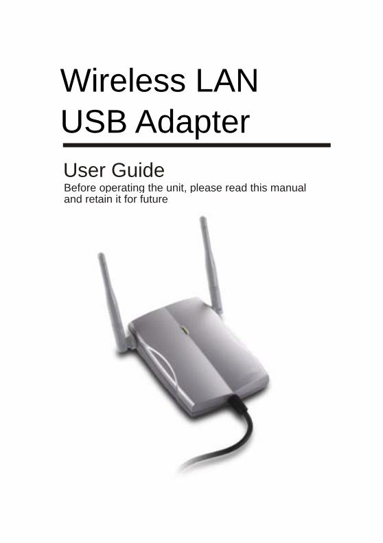
User Guide Before operating the unit, please read this manual and retain it for future Wireless LAN USB Adapter
-
Upload
johnsondon -
Category
Documents
-
view
366 -
download
2
Transcript of Wireless LAN USB Adapter
1
User Guide Before operating the unit, please read this manual and retain it for future
Wireless LAN USB Adapter
2
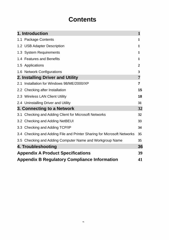
Contents
1. Introduction 1 1.1 Package Contents 1
1.2 USB Adapter Description 1
1.3 System Requirements 1
1.4 Features and Benefits 1
1.5 Applications 2 1.6 Network Configurations 3 2. Installing Driver and Utility 7 2.1 Installation for Windows 98/ME/2000/XP 7 2.2 Checking after Installation 15
2.3 Wireless LAN Client Utility 18
2.4 Uninstalling Driver and Utility 31 3. Connecting to a Network 323.1 Checking and Adding Client for Microsoft Networks 32
3.2 Checking and Adding NetBEUI 33
3.3 Checking and Adding TCP/IP 34
3.4 Checking and Adding File and Printer Sharing for Microsoft Networks 35
3.5 Checking and Adding Computer Name and Workgroup Name 35
4. Troubleshooting 36Appendix A Product Specifications 39 Appendix B Regulatory Compliance Information 41
1
Chapter 1 Introduction
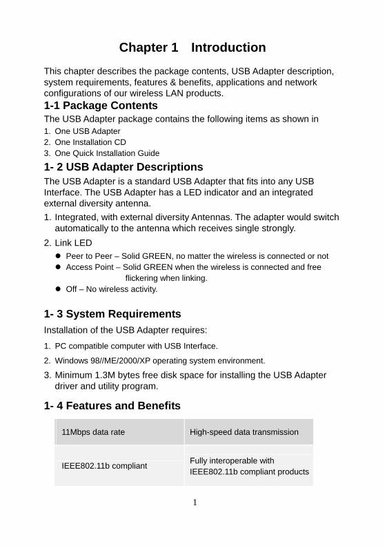
This chapter describes the package contents, USB Adapter description, system requirements, features & benefits, applications and network configurations of our wireless LAN products. 1-1 Package Contents The USB Adapter package contains the following items as shown in 1. One USB Adapter 2. One Installation CD 3. One Quick Installation Guide
1- 2 USB Adapter Descriptions The USB Adapter is a standard USB Adapter that fits into any USB Interface. The USB Adapter has a LED indicator and an integrated external diversity antenna. 1. Integrated, with external diversity Antennas. The adapter would switch
automatically to the antenna which receives single strongly. 2. Link LED
Peer to Peer – Solid GREEN, no matter the wireless is connected or not Access Point – Solid GREEN when the wireless is connected and free
flickering when linking. Off – No wireless activity.
1- 3 System Requirements Installation of the USB Adapter requires: 1. PC compatible computer with USB Interface.
2. Windows 98//ME/2000/XP operating system environment.
3. Minimum 1.3M bytes free disk space for installing the USB Adapter driver and utility program.
1- 4 Features and Benefits
11Mbps data rate High-speed data transmission
IEEE802.11b compliant Fully interoperable with IEEE802.11b compliant products
2
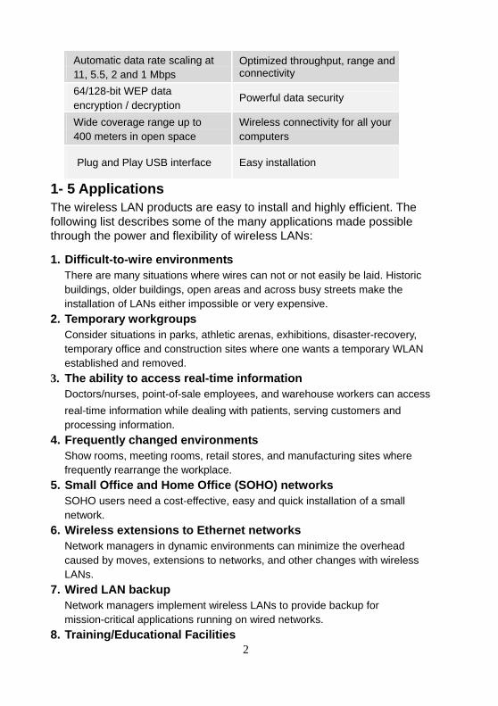
Automatic data rate scaling at 11, 5.5, 2 and 1 Mbps
Optimized throughput, range and connectivity
64/128-bit WEP data encryption / decryption Powerful data security
Wide coverage range up to 400 meters in open space
Wireless connectivity for all your computers
Plug and Play USB interface Easy installation
1- 5 Applications The wireless LAN products are easy to install and highly efficient. The following list describes some of the many applications made possible through the power and flexibility of wireless LANs: 1. Difficult-to-wire environments
There are many situations where wires can not or not easily be laid. Historic buildings, older buildings, open areas and across busy streets make the installation of LANs either impossible or very expensive.
2. Temporary workgroups Consider situations in parks, athletic arenas, exhibitions, disaster-recovery, temporary office and construction sites where one wants a temporary WLAN established and removed.
3. The ability to access real-time information Doctors/nurses, point-of-sale employees, and warehouse workers can access real-time information while dealing with patients, serving customers and processing information.
4. Frequently changed environments Show rooms, meeting rooms, retail stores, and manufacturing sites where frequently rearrange the workplace.
5. Small Office and Home Office (SOHO) networks SOHO users need a cost-effective, easy and quick installation of a small network.
6. Wireless extensions to Ethernet networks Network managers in dynamic environments can minimize the overhead caused by moves, extensions to networks, and other changes with wireless LANs.
7. Wired LAN backup Network managers implement wireless LANs to provide backup for mission-critical applications running on wired networks.
8. Training/Educational Facilities
3
Training sites at corporations and students at universities use wireless connectivity to ease access to information, information exchanges, and learning.
1- 6 Network Configurations To better understand how the wireless LAN products work together to create a wireless network, it might be helpful to depict a few of the possible wireless LAN USB Adapter network configurations. The wireless LAN products can be configured as: 1. Ad-hoc (or peer-to-peer) for departmental or SOHO LANs.
2. Infrastructure for enterprise LANs.
3. IP Sharing for 56K/ISDN TA/Cable/DSL Modem – Connect Internet and your SOHO network.
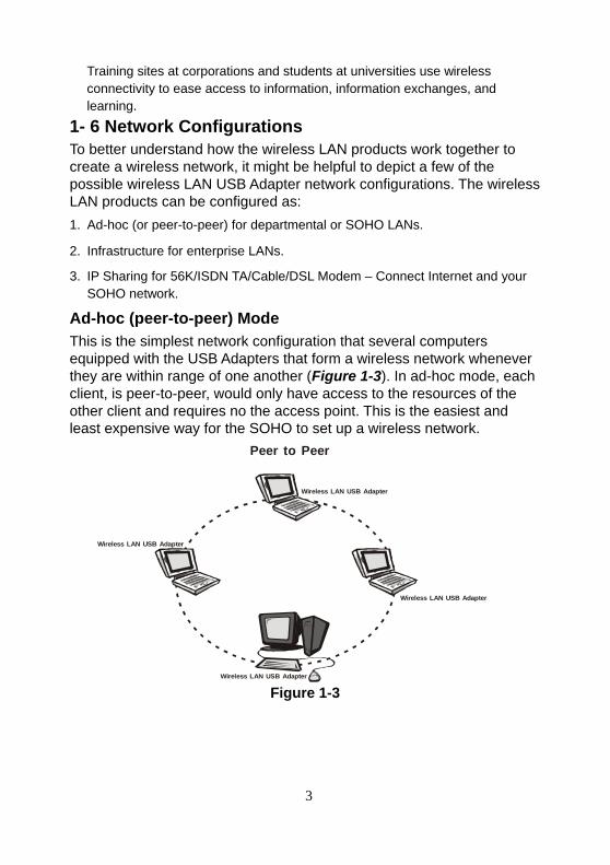
Ad-hoc (peer-to-peer) Mode This is the simplest network configuration that several computers equipped with the USB Adapters that form a wireless network whenever they are within range of one another (Figure 1-3). In ad-hoc mode, each client, is peer-to-peer, would only have access to the resources of the other client and requires no the access point. This is the easiest and least expensive way for the SOHO to set up a wireless network.
Figure 1-3
Peer to Peer
Wireless LAN USB Adapter
Wireless LAN USB Adapter
Wireless LAN USB Adapter
Wireless LAN USB Adapter
4
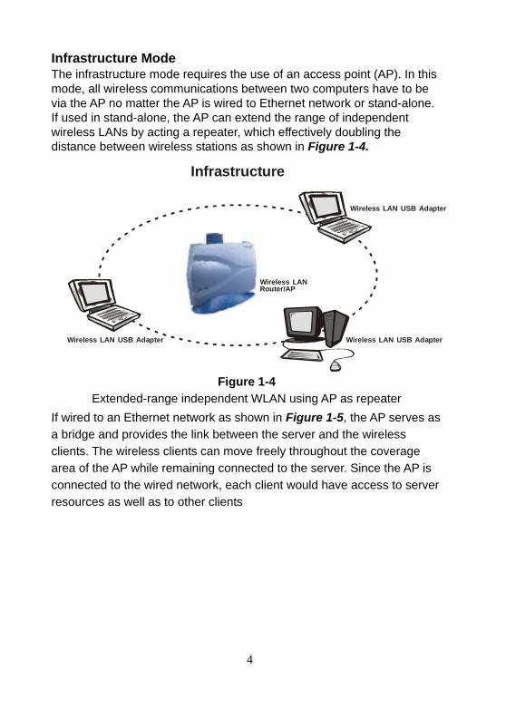
Infrastructure Mode The infrastructure mode requires the use of an access point (AP). In this mode, all wireless communications between two computers have to be via the AP no matter the AP is wired to Ethernet network or stand-alone. If used in stand-alone, the AP can extend the range of independent wireless LANs by acting a repeater, which effectively doubling the distance between wireless stations as shown in Figure 1-4.
Figure 1-4 Extended-range independent WLAN using AP as repeater
If wired to an Ethernet network as shown in Figure 1-5, the AP serves as a bridge and provides the link between the server and the wireless clients. The wireless clients can move freely throughout the coverage area of the AP while remaining connected to the server. Since the AP is connected to the wired network, each client would have access to server resources as well as to other clients
Wireless LAN USB Adapter
Wireless LAN Router/AP
Infrastructure
Wireless LAN USB Adapter Wireless LAN USB Adapter
5
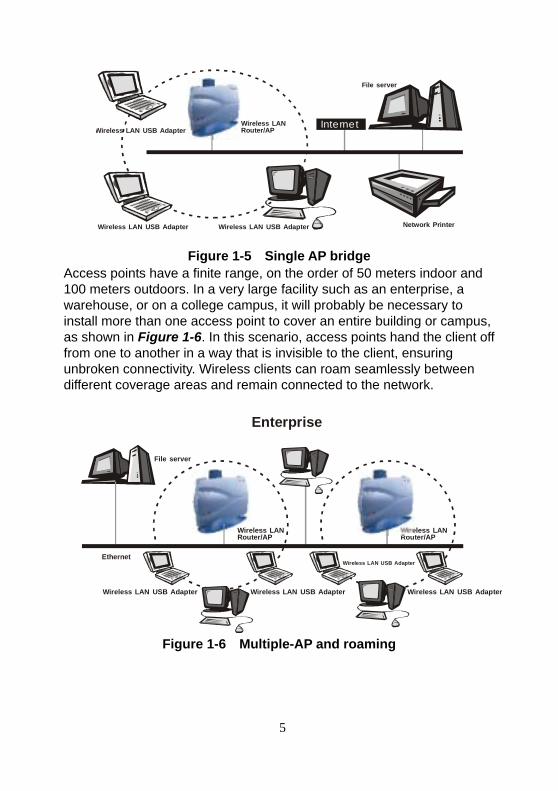
Figure 1-5 Single AP bridge
Access points have a finite range, on the order of 50 meters indoor and 100 meters outdoors. In a very large facility such as an enterprise, a warehouse, or on a college campus, it will probably be necessary to install more than one access point to cover an entire building or campus, as shown in Figure 1-6. In this scenario, access points hand the client off from one to another in a way that is invisible to the client, ensuring unbroken connectivity. Wireless clients can roam seamlessly between different coverage areas and remain connected to the network.
Figure 1-6 Multiple-AP and roaming
File server
Network Printer
InternetWireless LAN USB Adapter
Wireless LAN Router/AP
Wireless LAN USB Adapter Wireless LAN USB Adapter
File server
Enterprise
Ethernet
Wireless LAN USB Adapter
Wireless LAN Router/AP
Wireless LAN Router/AP
Wireless LAN USB Adapter Wireless LAN USB Adapter
Wireless LAN USB Adapter
6
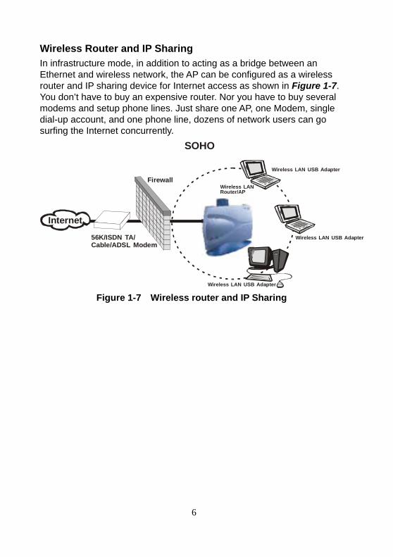
Wireless Router and IP Sharing In infrastructure mode, in addition to acting as a bridge between an Ethernet and wireless network, the AP can be configured as a wireless router and IP sharing device for Internet access as shown in Figure 1-7. You don’t have to buy an expensive router. Nor you have to buy several modems and setup phone lines. Just share one AP, one Modem, single dial-up account, and one phone line, dozens of network users can go surfing the Internet concurrently.
Figure 1-7 Wireless router and IP Sharing
56K/ISDN TA/Cable/ADSL Modem
Firewall
Internet
SOHO
Wireless LAN USB Adapter
Wireless LAN Router/AP
Wireless LAN USB Adapter
Wireless LAN USB Adapter
7
8
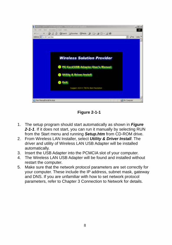
Figure 2-1-1 1. The setup program should start automatically as shown in Figure
2-1-1. If it does not start, you can run it manually by selecting RUN from the Start menu and running Setup.htm from CD-ROM drive.
2. From Wireless LAN Installer, select Utility & Driver Install. The driver and utility of Wireless LAN USB Adapter will be installed automatically.
3. Insert the USB Adapter into the PCMCIA slot of your computer. 4. The Wireless LAN USB Adapter will be found and installed without
restart the computer. 5. Make sure that the network protocol parameters are set correctly for
your computer. These include the IP address, subnet mask, gateway and DNS. If you are unfamiliar with how to set network protocol parameters, refer to Chapter 3 Connection to Network for details.
9
10
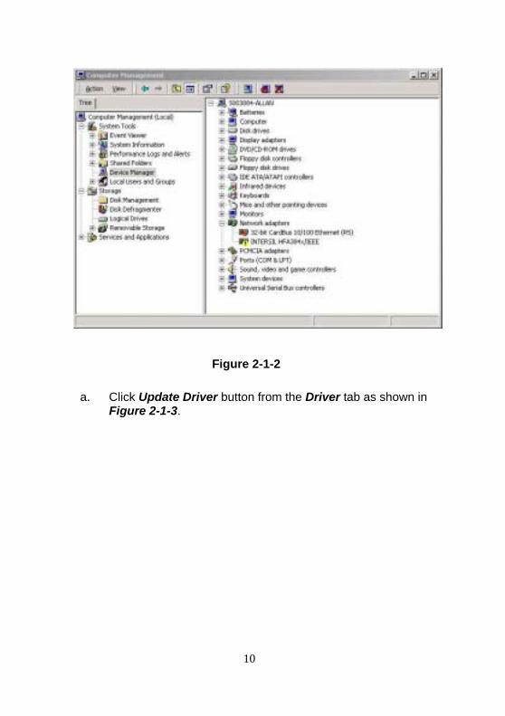
Figure 2-1-2
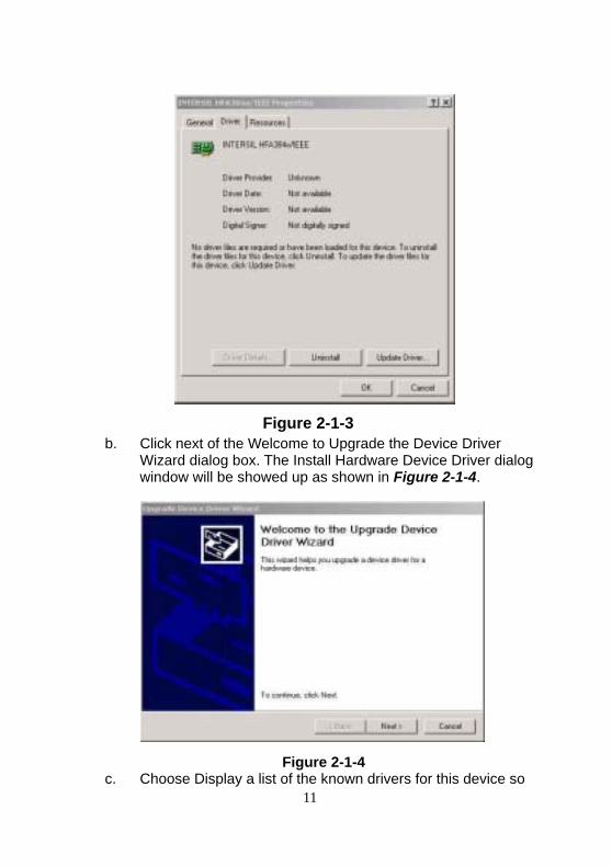
a. Click Update Driver button from the Driver tab as shown in
Figure 2-1-3.
11
Figure 2-1-3 b. Click next of the Welcome to Upgrade the Device Driver
Wizard dialog box. The Install Hardware Device Driver dialog window will be showed up as shown in Figure 2-1-4.
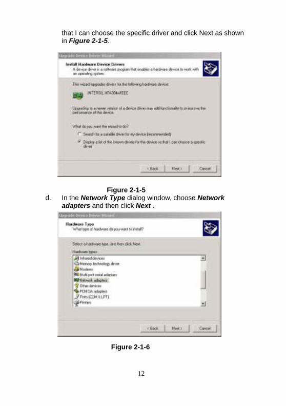
Figure 2-1-4 c. Choose Display a list of the known drivers for this device so
12
that I can choose the specific driver and click Next as shown in Figure 2-1-5.
Figure 2-1-5 d. In the Network Type dialog window, choose Network
adapters and then click Next .
Figure 2-1-6
13
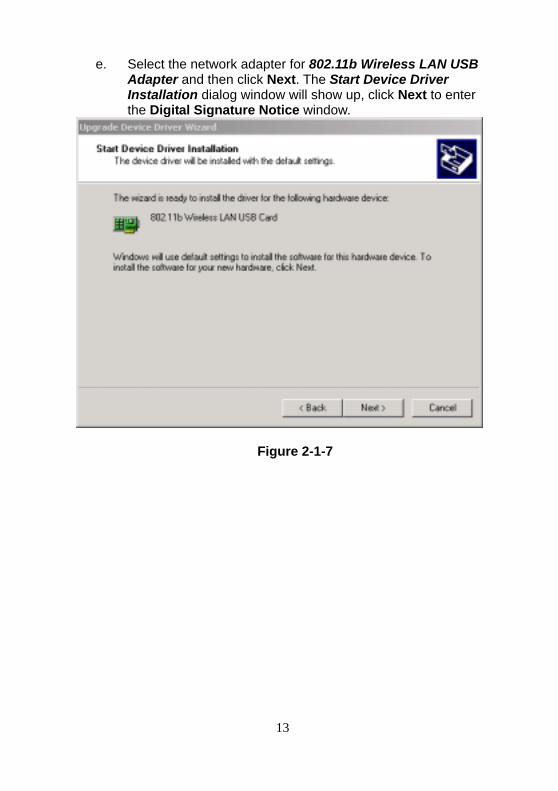
e. Select the network adapter for 802.11b Wireless LAN USB Adapter and then click Next. The Start Device Driver Installation dialog window will show up, click Next to enter the Digital Signature Notice window.
Figure 2-1-7
14
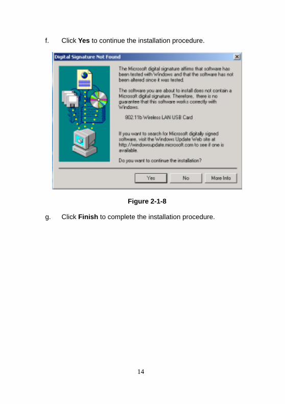
f. Click Yes to continue the installation procedure.
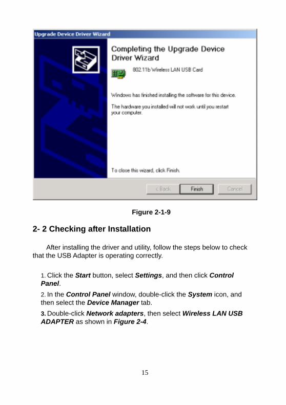
Figure 2-1-8 g. Click Finish to complete the installation procedure.
15
Figure 2-1-9 2- 2 Checking after Installation
After installing the driver and utility, follow the steps below to check
that the USB Adapter is operating correctly.
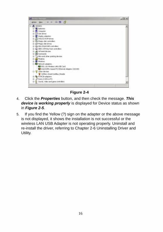
1. Click the Start button, select Settings, and then click Control Panel. 2. In the Control Panel window, double-click the System icon, and then select the Device Manager tab. 3. Double-click Network adapters, then select Wireless LAN USB ADAPTER as shown in Figure 2-4.
16
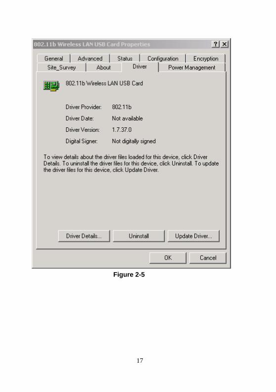
Figure 2-4 4. Click the Properties button, and then check the message. This
device is working properly is displayed for Device status as shown in Figure 2-5.
5. If you find the Yellow (?) sign on the adapter or the above message is not displayed, it shows the installation is not successful or the wireless LAN USB Adapter is not operating properly. Uninstall and re-install the driver, referring to Chapter 2-6 Uninstalling Driver and Utility.
17
Figure 2-5
18
2- 3 Wireless LAN Client Utility
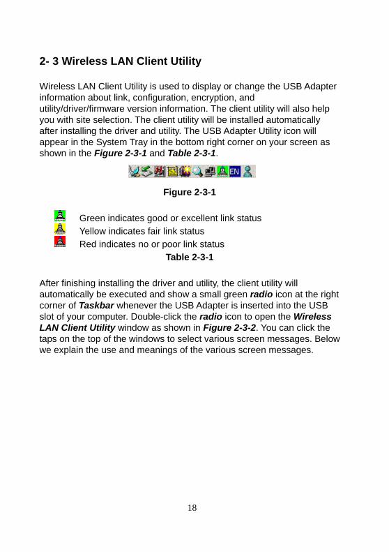
Wireless LAN Client Utility is used to display or change the USB Adapter information about link, configuration, encryption, and utility/driver/firmware version information. The client utility will also help you with site selection. The client utility will be installed automatically after installing the driver and utility. The USB Adapter Utility icon will appear in the System Tray in the bottom right corner on your screen as shown in the Figure 2-3-1 and Table 2-3-1.
Figure 2-3-1
Green indicates good or excellent link status Yellow indicates fair link status Red indicates no or poor link status
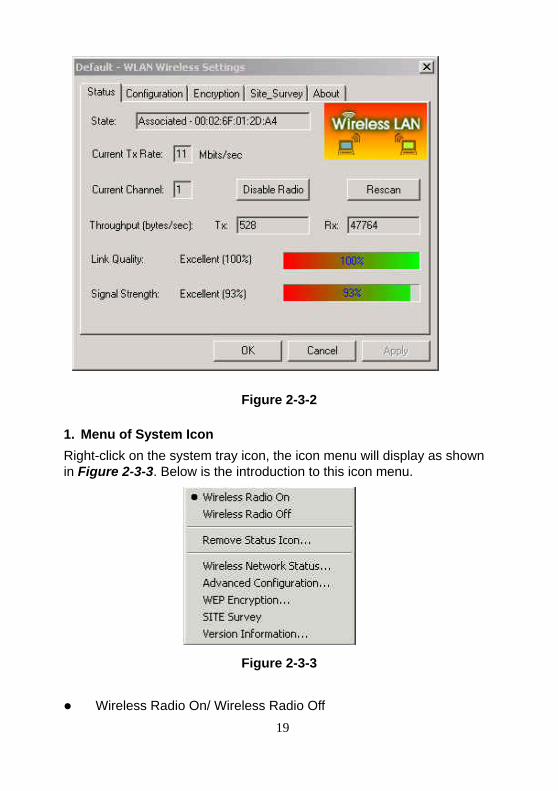
Table 2-3-1 After finishing installing the driver and utility, the client utility will automatically be executed and show a small green radio icon at the right corner of Taskbar whenever the USB Adapter is inserted into the USB slot of your computer. Double-click the radio icon to open the Wireless LAN Client Utility window as shown in Figure 2-3-2. You can click the taps on the top of the windows to select various screen messages. Below we explain the use and meanings of the various screen messages.
19
Figure 2-3-2
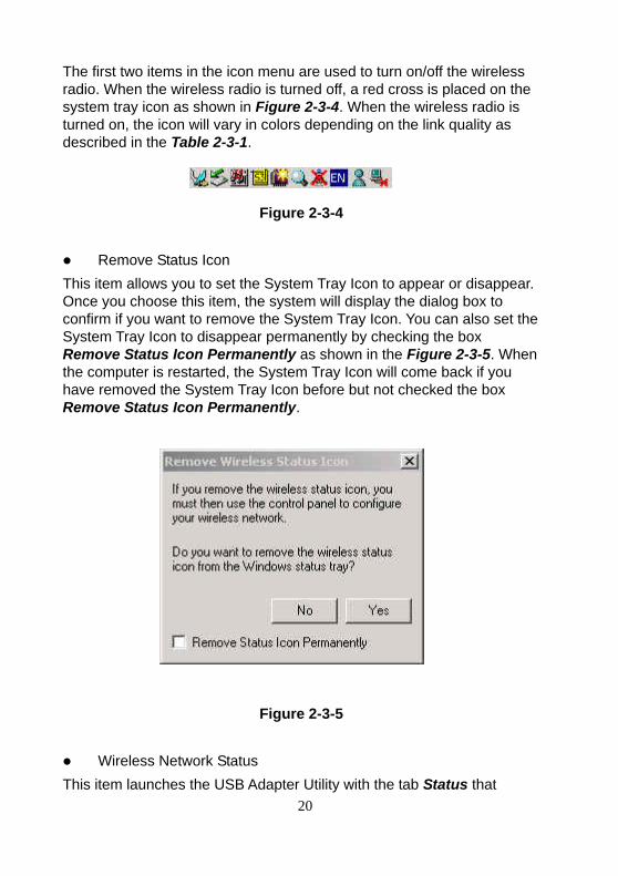
1. Menu of System Icon Right-click on the system tray icon, the icon menu will display as shown in Figure 2-3-3. Below is the introduction to this icon menu.
Figure 2-3-3 Wireless Radio On/ Wireless Radio Off
20
The first two items in the icon menu are used to turn on/off the wireless radio. When the wireless radio is turned off, a red cross is placed on the system tray icon as shown in Figure 2-3-4. When the wireless radio is turned on, the icon will vary in colors depending on the link quality as described in the Table 2-3-1.
Figure 2-3-4 Remove Status Icon
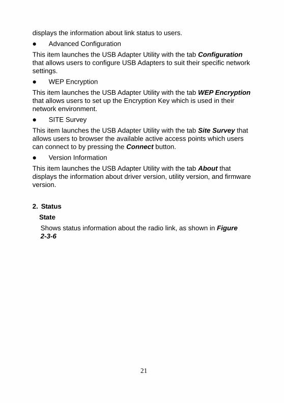
This item allows you to set the System Tray Icon to appear or disappear. Once you choose this item, the system will display the dialog box to confirm if you want to remove the System Tray Icon. You can also set the System Tray Icon to disappear permanently by checking the box Remove Status Icon Permanently as shown in the Figure 2-3-5. When the computer is restarted, the System Tray Icon will come back if you have removed the System Tray Icon before but not checked the box Remove Status Icon Permanently.
Figure 2-3-5 Wireless Network Status
This item launches the USB Adapter Utility with the tab Status that
21
displays the information about link status to users. Advanced Configuration
This item launches the USB Adapter Utility with the tab Configuration that allows users to configure USB Adapters to suit their specific network settings. WEP Encryption
This item launches the USB Adapter Utility with the tab WEP Encryption that allows users to set up the Encryption Key which is used in their network environment. SITE Survey
This item launches the USB Adapter Utility with the tab Site Survey that allows users to browser the available active access points which users can connect to by pressing the Connect button. Version Information
This item launches the USB Adapter Utility with the tab About that displays the information about driver version, utility version, and firmware version. 2. Status
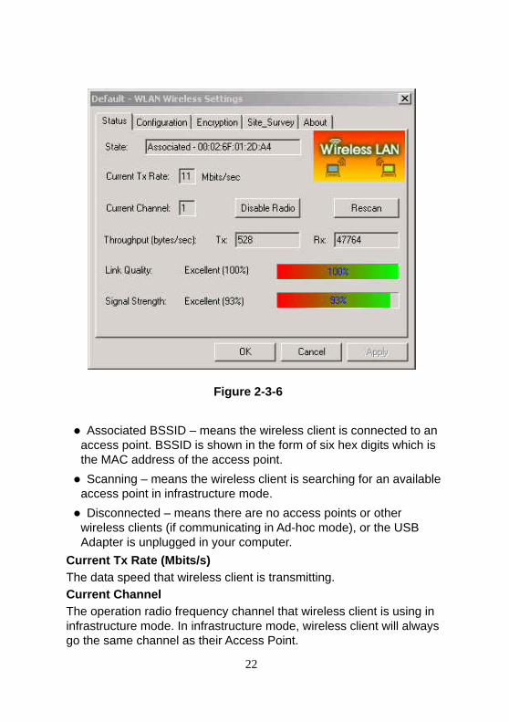
State Shows status information about the radio link, as shown in Figure 2-3-6
22
Figure 2-3-6
Associated BSSID – means the wireless client is connected to an access point. BSSID is shown in the form of six hex digits which is the MAC address of the access point. Scanning – means the wireless client is searching for an available access point in infrastructure mode. Disconnected – means there are no access points or other wireless clients (if communicating in Ad-hoc mode), or the USB Adapter is unplugged in your computer.
Current Tx Rate (Mbits/s) The data speed that wireless client is transmitting. Current Channel The operation radio frequency channel that wireless client is using in infrastructure mode. In infrastructure mode, wireless client will always go the same channel as their Access Point.
23
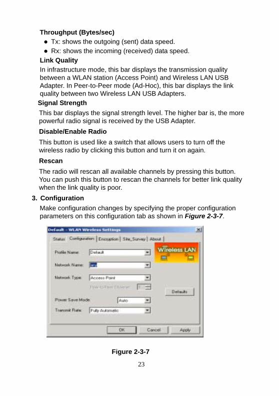
Throughput (Bytes/sec) Tx: shows the outgoing (sent) data speed. Rx: shows the incoming (received) data speed.
Link Quality In infrastructure mode, this bar displays the transmission quality between a WLAN station (Access Point) and Wireless LAN USB Adapter. In Peer-to-Peer mode (Ad-Hoc), this bar displays the link quality between two Wireless LAN USB Adapters.
Signal Strength This bar displays the signal strength level. The higher bar is, the more powerful radio signal is received by the USB Adapter. Disable/Enable Radio This button is used like a switch that allows users to turn off the wireless radio by clicking this button and turn it on again. Rescan The radio will rescan all available channels by pressing this button. You can push this button to rescan the channels for better link quality when the link quality is poor.
3. Configuration Make configuration changes by specifying the proper configuration parameters on this configuration tab as shown in Figure 2-3-7.
Figure 2-3-7
24
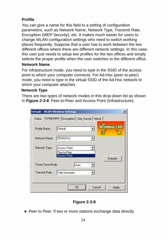
Profile You can give a name for this field to a setting of configuration parameters, such as Network Name, Network Type, Transmit Rate, Encryption (WEP Security), etc. It makes much easier for users to change WLAN configuration settings who need to switch working places frequently. Suppose that a user has to work between the two different offices where there are different network settings. In this case, this user just needs to setup two profiles for the two offices and simply selects the proper profile when the user switches to the different office. Network Name For infrastructure mode, you need to type in the SSID of the access point to which your computer connects. For Ad-Hoc (peer-to-peer) mode, you need to type in the virtual SSID of the Ad-Hoc network to which your computer attaches. Network Type There are two types of network modes in this drop-down list as shown in Figure 2-3-8, Peer-to-Peer and Access Point (Infrastructure).
Figure 2-3-8
Peer to Peer: If two or more stations exchange data directly
25
without an access point, you need to select Peer-to-Peer mode. Each station in a Peer-to-Peer (Ad-Hoc) network must specify the same network name (SSID) and peer-to-peer channel. Access Point: If at least one access point involves in the communications in a group of stations, you need to select Infrastructure mode. Each station needs to specify the same network name (SSID) as the access point. Please refer to the section 1-6 for more details about peer-to-peer mode and Access Point (infrastructure) mode.
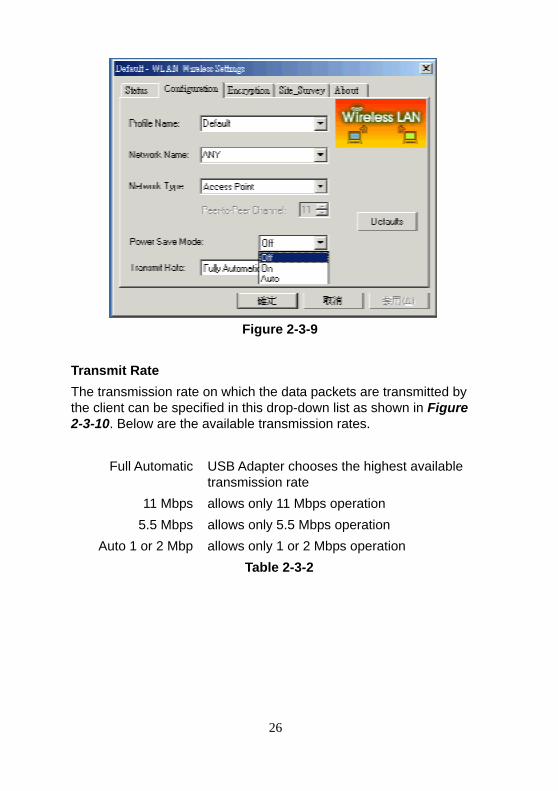
Peer-to-Peer Channel This option is just for Peer-to-Peer (Ad-Hoc) mode. You need to specify a channel on which the communications are established. Each station in a Peer-to-Peer (Ad-Hoc) network must specify the same channel and network type (SSID). Power Save Mode Power Save function as shown in figure 2-3-9 .This function can conserve more battery energy and extend the battery life. This function has three options for power save mode. Below is detailed description.
1.On: Enable Power Save function. 2.Off: Disable Power Save function. 3.Auto: Utility will automatically detect what kind of power
supply a machine uses and then determine to enable or disable Power Save function. If device uses battery, Power Save Mode is set to on.If device uses AC Power, Power Save Mode is set to off.
26
Figure 2-3-9
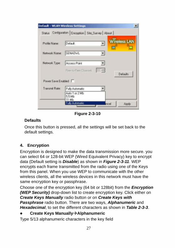
Transmit Rate The transmission rate on which the data packets are transmitted by the client can be specified in this drop-down list as shown in Figure 2-3-10. Below are the available transmission rates.
Full Automatic USB Adapter chooses the highest available transmission rate
11 Mbps allows only 11 Mbps operation 5.5 Mbps allows only 5.5 Mbps operation
Auto 1 or 2 Mbp allows only 1 or 2 Mbps operation Table 2-3-2
27
Figure 2-3-10 Defaults Once this button is pressed, all the settings will be set back to the default settings.
4. Encryption Encryption is designed to make the data transmission more secure. you can select 64 or 128-bit WEP (Wired Equivalent Privacy) key to encrypt data (Default setting is Disable) as shown in Figure 2-3-11. WEP encrypts each frame transmitted from the radio using one of the Keys from this panel. When you use WEP to communicate with the other wireless clients, all the wireless devices in this network must have the same encryption key or passphrase. Choose one of the encryption key (64 bit or 128bit) from the Encryption (WEP Security) drop-down list to create encryption key. Click either on Create Keys Manually radio button or on Create Keys with Passphrase radio button. There are two ways, Alphanumeric and Hexadecimal, to set the different characters as shown in Table 2-3-3. Create Keys Manually Alphanumeric
Type 5/13 alphanumeric characters in the key field
28
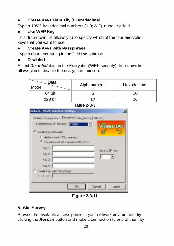
Create Keys Manually Hexadecimal Type a 10/26 hexadecimal numbers (1-9; A-F) in the key field Use WEP Key
This drop-down list allows you to specify which of the four encryption keys that you want to use. Create Keys with Passphrase
Type a character string in the field Passphrase. Disabled
Select Disabled item in the Encryption(WEP security) drop-down list allows you to disable the encryption function.
Data Mode Alphanumeric Hexadecimal
64 bit 5 10 128 bit 13 26
Table 2-3-3
Figure 2-3-11
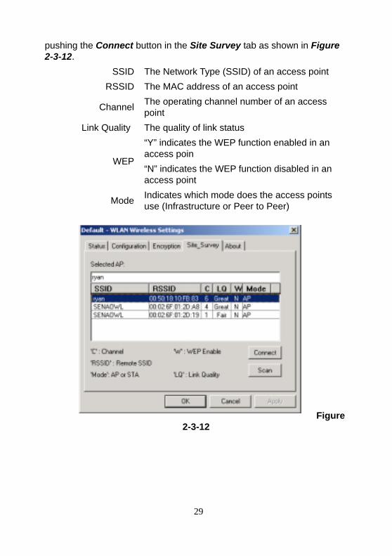
5. Site Survey Browse the available access points in your network environment by clicking the Rescan button and make a connection to one of them by
29
pushing the Connect button in the Site Survey tab as shown in Figure 2-3-12.
SSID The Network Type (SSID) of an access point RSSID The MAC address of an access point
Channel The operating channel number of an access point
Link Quality The quality of link status
WEP
“Y” indicates the WEP function enabled in an access poin “N” indicates the WEP function disabled in an access point
Mode Indicates which mode does the access points use (Infrastructure or Peer to Peer)
Figure 2-3-12
30
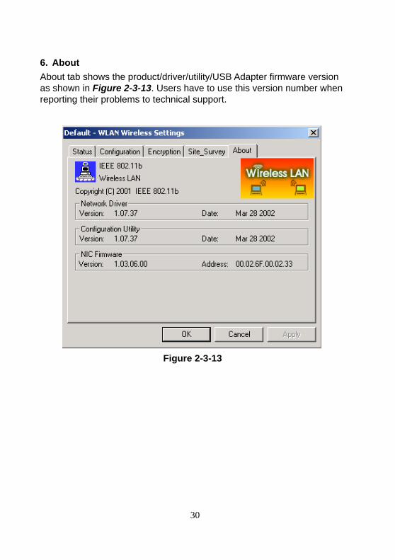
6. About About tab shows the product/driver/utility/USB Adapter firmware version as shown in Figure 2-3-13. Users have to use this version number when reporting their problems to technical support.
Figure 2-3-13
31
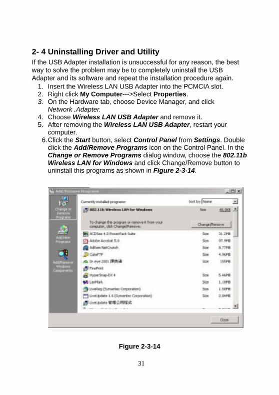
2- 4 Uninstalling Driver and Utility If the USB Adapter installation is unsuccessful for any reason, the best way to solve the problem may be to completely uninstall the USB Adapter and its software and repeat the installation procedure again.
1. Insert the Wireless LAN USB Adapter into the PCMCIA slot. 2. Right click My Computer--->Select Properties. 3. On the Hardware tab, choose Device Manager, and click
Network .Adapter. 4. Choose Wireless LAN USB Adapter and remove it. 5. After removing the Wireless LAN USB Adapter, restart your
computer. 6. Click the Start button, select Control Panel from Settings. Double
click the Add/Remove Programs icon on the Control Panel. In the Change or Remove Programs dialog window, choose the 802.11b Wireless LAN for Windows and click Change/Remove button to uninstall this programs as shown in Figure 2-3-14.
Figure 2-3-14
32
Chapter 3 Connecting to a Network
This chapter describes how to prepare for connection to network after install the USB Adapter drivers and utility. The following is required for all computers if you want to connect to a network. 1. Check Client for Microsoft Networks is installed. 2. Check NetBEUI -> Wireless LAN USB Adapter installed. 3. Check TCP/IP -> Wireless LAN USB Adapter is installed. 4. Check file and printer sharing for Microsoft Networks. 5. Check computer name and workgroup name. 3-1 Checking and Adding Client for Microsoft Networks The Client for Microsoft Networks enables you to connect to other Microsoft Windows computers and servers and use the files and printers shared on them. If you works on Microsoft network environment, you need to set up Client for Microsoft Networks. 1. After finishing installing the driver & utility and rebooting the computer as
described in Chapter 2. The computer will show a dialog box titled Enter Network Password dialog box. Enter your password if it had been set or just click Cancel.
2. Click Start button, select Settings and then click Control Panel to open the Control Panel window.
3. In the Control Panel window, double-click the Network icon to open the Network dialog box.
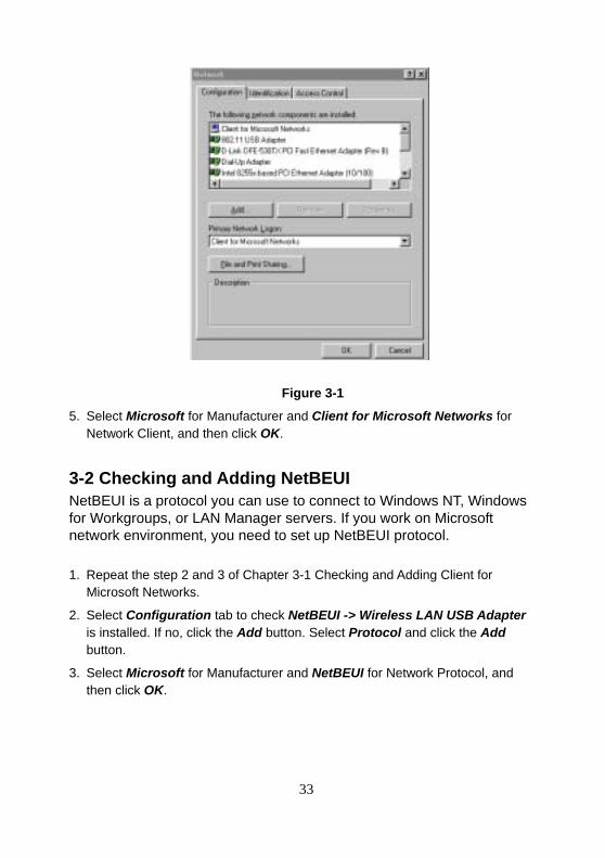
4. Select Configuration tab to check Client for Microsoft Networks is installed as shown in Figure 3-1. If no, click the Add button. Select Client and click the Add button.
33
Figure 3-1
5. Select Microsoft for Manufacturer and Client for Microsoft Networks for Network Client, and then click OK.
3-2 Checking and Adding NetBEUI NetBEUI is a protocol you can use to connect to Windows NT, Windows for Workgroups, or LAN Manager servers. If you work on Microsoft network environment, you need to set up NetBEUI protocol. 1. Repeat the step 2 and 3 of Chapter 3-1 Checking and Adding Client for
Microsoft Networks.
2. Select Configuration tab to check NetBEUI -> Wireless LAN USB Adapter is installed. If no, click the Add button. Select Protocol and click the Add button.
3. Select Microsoft for Manufacturer and NetBEUI for Network Protocol, and then click OK.
34
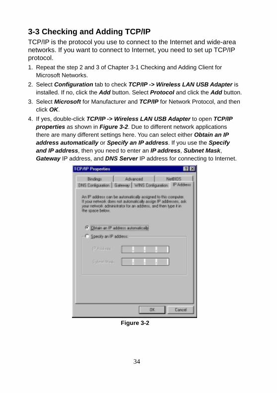
3-3 Checking and Adding TCP/IP TCP/IP is the protocol you use to connect to the Internet and wide-area networks. If you want to connect to Internet, you need to set up TCP/IP protocol. 1. Repeat the step 2 and 3 of Chapter 3-1 Checking and Adding Client for
Microsoft Networks. 2. Select Configuration tab to check TCP/IP -> Wireless LAN USB Adapter is
installed. If no, click the Add button. Select Protocol and click the Add button. 3. Select Microsoft for Manufacturer and TCP/IP for Network Protocol, and then
click OK. 4. If yes, double-click TCP/IP -> Wireless LAN USB Adapter to open TCP/IP
properties as shown in Figure 3-2. Due to different network applications there are many different settings here. You can select either Obtain an IP address automatically or Specify an IP address. If you use the Specify and IP address, then you need to enter an IP address, Subnet Mask, Gateway IP address, and DNS Server IP address for connecting to Internet.
Figure 3-2
35
3-4 Checking and Adding File and Printer Sharing for Microsoft Networks
File and printer sharing for Microsoft networks gives you the ability to share your files or printers with Windows NT and Windows for Workgroups computers. If you want to share your files or printers with Microsoft networks, you need to set up this service. 1. Repeat the step 2 and 3 of Chapter 3-1 Checking and Adding Client for
Microsoft Networks.
2. Select Configuration tab to check File and printer sharing for Microsoft Networks is installed. If no, click the File and Printer Sharing button.
3. In the File and Print Sharing window, select what you need, and click OK. File and printer sharing for Microsoft Networks, and then click OK.
3-5 Checking and Adding Computer Name & Workgroup Name Windows uses the computer name and workgroup name to identify your computer on the network. Please enter a unique name for your computer, the workgroup it will appear in, and a short description of the computer. 1. Repeat the step 2 and 3 of Chapter 3-1 Checking and Adding Client for
Microsoft Networks.
2. Select Identification tab (Windows 98) or User Information tab to check the computer name, workgroup and computer description are entered. If no, enter a computer name, a workgroup name and then click OK. The description field may be left blank. If you want to share data with other persons, make sure you have the same workgroup name.
36
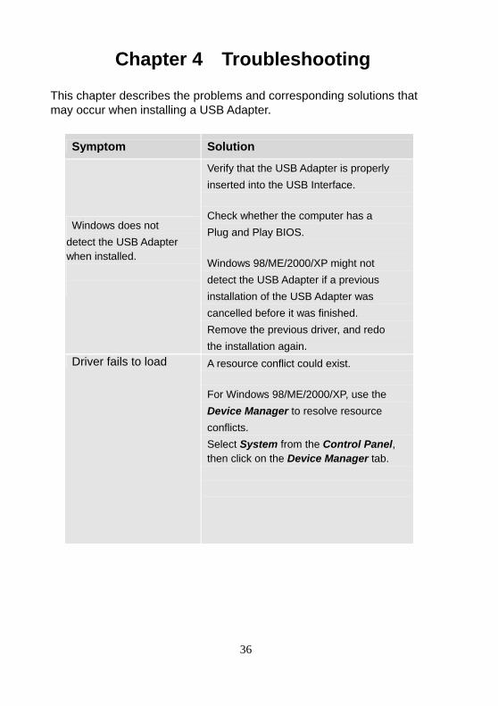
Chapter 4 Troubleshooting
This chapter describes the problems and corresponding solutions that may occur when installing a USB Adapter.
Symptom Solution
Windows does not detect the USB Adapter when installed.
Verify that the USB Adapter is properly inserted into the USB Interface. Check whether the computer has a Plug and Play BIOS. Windows 98/ME/2000/XP might not detect the USB Adapter if a previous installation of the USB Adapter was cancelled before it was finished. Remove the previous driver, and redo the installation again.
Driver fails to load A resource conflict could exist. For Windows 98/ME/2000/XP, use the Device Manager to resolve resource conflicts. Select System from the Control Panel, then click on the Device Manager tab.
37
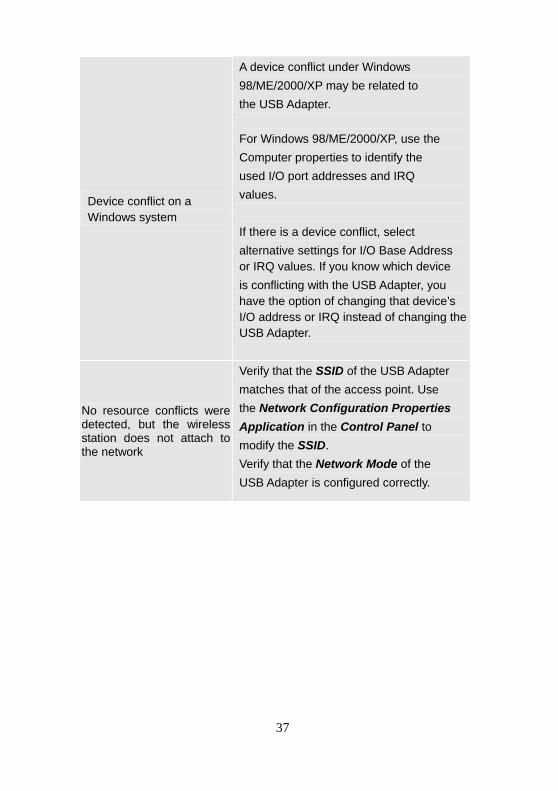
Device conflict on a Windows system
A device conflict under Windows 98/ME/2000/XP may be related to the USB Adapter. For Windows 98/ME/2000/XP, use the Computer properties to identify the used I/O port addresses and IRQ values.
If there is a device conflict, select alternative settings for I/O Base Address or IRQ values. If you know which device is conflicting with the USB Adapter, you have the option of changing that device’s I/O address or IRQ instead of changing the USB Adapter.
No resource conflicts were detected, but the wireless station does not attach to the network
Verify that the SSID of the USB Adapter matches that of the access point. Use the Network Configuration Properties Application in the Control Panel to modify the SSID. Verify that the Network Mode of the USB Adapter is configured correctly.
38
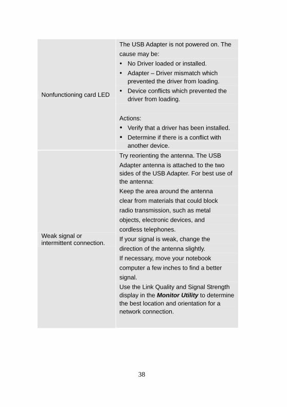
Nonfunctioning card LED
The USB Adapter is not powered on. The cause may be: No Driver loaded or installed. Adapter – Driver mismatch which
prevented the driver from loading. Device conflicts which prevented the
driver from loading. Actions: Verify that a driver has been installed. Determine if there is a conflict with
another device.
Weak signal or intermittent connection.
Try reorienting the antenna. The USB Adapter antenna is attached to the two sides of the USB Adapter. For best use of the antenna: Keep the area around the antenna clear from materials that could block radio transmission, such as metal objects, electronic devices, and cordless telephones. If your signal is weak, change the direction of the antenna slightly. If necessary, move your notebook computer a few inches to find a better signal. Use the Link Quality and Signal Strength display in the Monitor Utility to determine the best location and orientation for a network connection.
39
40
41
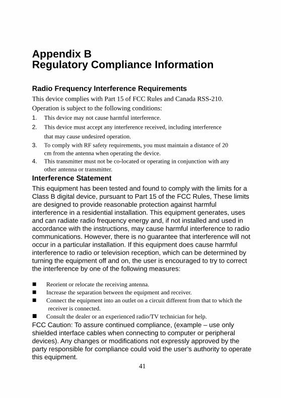
Appendix B Regulatory Compliance Information Radio Frequency Interference Requirements This device complies with Part 15 of FCC Rules and Canada RSS-210. Operation is subject to the following conditions: 1. This device may not cause harmful interference. 2. This device must accept any interference received, including interference
that may cause undesired operation. 3. To comply with RF safety requirements, you must maintain a distance of 20
cm from the antenna when operating the device. 4. This transmitter must not be co-located or operating in conjunction with any
other antenna or transmitter. Interference Statement This equipment has been tested and found to comply with the limits for a Class B digital device, pursuant to Part 15 of the FCC Rules, These limits are designed to provide reasonable protection against harmful interference in a residential installation. This equipment generates, uses and can radiate radio frequency energy and, if not installed and used in accordance with the instructions, may cause harmful interference to radio communications. However, there is no guarantee that interference will not occur in a particular installation. If this equipment does cause harmful interference to radio or television reception, which can be determined by turning the equipment off and on, the user is encouraged to try to correct the interference by one of the following measures: Reorient or relocate the receiving antenna. Increase the separation between the equipment and receiver. Connect the equipment into an outlet on a circuit different from that to which the
receiver is connected. Consult the dealer or an experienced radio/TV technician for help.
FCC Caution: To assure continued compliance, (example – use only shielded interface cables when connecting to computer or peripheral devices). Any changes or modifications not expressly approved by the party responsible for compliance could void the user’s authority to operate this equipment.