Wireless Hart System Engineering Guide Rev 2.3
83
© 2010 Emerson Pr ocess Manage ment All rights reserved. ROSEMOUNT INC. IEC 62591 WirelessHART ® System Engineering Guide Revision 2.3 This document provides guidelines for implementing WirelessHART systems in the project process
-
Upload
ahmedbader -
Category
Documents
-
view
219 -
download
0
Transcript of Wireless Hart System Engineering Guide Rev 2.3

8/3/2019 Wireless Hart System Engineering Guide Rev 2.3
http://slidepdf.com/reader/full/wireless-hart-system-engineering-guide-rev-23 1/83
© 2010 Emerson Process Management All rights reserved.
ROSEMOUNT INC.
IEC 62591 WirelessHART®
System Engineering GuideRevision 2.3
This document provides guidelines for implementing WirelessHART systems in the project process
8/3/2019 Wireless Hart System Engineering Guide Rev 2.3
http://slidepdf.com/reader/full/wireless-hart-system-engineering-guide-rev-23 2/83
System Engineering Guide
Revision 2.3
November 2010 WirelessHART
Page 2 of 83 © 2010 Emerson Process Management. All rights reserved.
System Engineering Guide for WirelessHART
Contents
System Engineering Guide for WirelessHART ............................................................................................... 2
Preface ...................................................................................................................................................... 5
Authors ...................................................................................................................................................... 5
Reviewers .................................................................................................................................................. 5
Revision ..................................................................................................................................................... 6
Disclaimer.................................................................................................................................................. 6
Feedback ................................................................................................................................................... 6
Section 1 Introduction .............................................................................................................................. 7
Purpose ..................................................................................................................................................... 7
Scope ......................................................................................................................................................... 7
Definition .................................................................................................................................................. 7
Section 2 Definitions .................................................................................................................................... 8
Acronyms ................................................................................................................................................ 11
Section 3 Project Concepts ..................................................................................................................... 11
Pre-FEED .................................................................................................................................................. 11
Technology Evaluation ............................................................................................................................ 12FEED ........................................................................................................................................................ 13
Detailed Engineering ............................................................................................................................... 15
Factory Acceptance Test ......................................................................................................................... 18
Installation .............................................................................................................................................. 18
Commissioning ........................................................................................................................................ 19
Section 4 Document Requirements ........................................................................................................ 20
Drawings ................................................................................................................................................. 20
ISA Documentation ................................................................................................................................. 20
Control Narrative .................................................................................................................................... 21
Instrument Index/Database .................................................................................................................... 21
Instrument Data Sheets .......................................................................................................................... 21
Material Requisitions .............................................................................................................................. 21
Manufacturer Documentation ................................................................................................................ 21
Project Management .............................................................................................................................. 21

8/3/2019 Wireless Hart System Engineering Guide Rev 2.3
http://slidepdf.com/reader/full/wireless-hart-system-engineering-guide-rev-23 3/83
System Engineering Guide
Revision 2.3
November 2010 WirelessHART
Page 3 of 83 © 2010 Emerson Process Management. All rights reserved.
Section 5 Field Device Requirements ..................................................................................................... 23
Support for WirelessHART Functionality ................................................................................................ 23
Device Diagnostics .................................................................................................................................. 23
Field Device Power .................................................................................................................................. 24
Field Device Security ............................................................................................................................... 26
Approvals ................................................................................................................................................ 27
Accessibility ............................................................................................................................................. 27
Section 6 Ancillary Device Requirements ............................................................................................... 29
Gateways ................................................................................................................................................. 29
Wireless Repeaters ................................................................................................................................. 30
WirelessHART Adapters .......................................................................................................................... 30
Section 7 WirelessHART Field Network Design Guidelines ..................................................................... 32
Wireless Project Overview ...................................................................................................................... 32
WirelessHART Field Network Design ...................................................................................................... 33
Scoping .................................................................................................................................................... 33
Designing ................................................................................................................................................. 39
Spare Capacity and Expansion ................................................................................................................ 44
Fortifying ................................................................................................................................................. 45
WirelessHART Availability and Redundancy ........................................................................................... 46
WirelessHART Security ............................................................................................................................ 46
Section 8 Host System Requirements ..................................................................................................... 47
Use of Standard Protocols ...................................................................................................................... 47
Wireless Host System .............................................................................................................................. 47
Host Integration ...................................................................................................................................... 49
Interoperability ....................................................................................................................................... 50
Host System Support for WirelessHART Functionality ............................................................................ 51
Configuration Tools ................................................................................................................................. 51
Control System Graphics ......................................................................................................................... 51
Node Addressing and Naming Conventions ........................................................................................... 52Alarms and Alerts .................................................................................................................................... 52
Maintenance Station ............................................................................................................................... 52
Historian .................................................................................................................................................. 52
8/3/2019 Wireless Hart System Engineering Guide Rev 2.3
http://slidepdf.com/reader/full/wireless-hart-system-engineering-guide-rev-23 4/83
System Engineering Guide
Revision 2.3
November 2010 WirelessHART
Page 4 of 83 © 2010 Emerson Process Management. All rights reserved.
Section 9 Factory Acceptance Testing Requirements............................................................................. 53
Introduction ............................................................................................................................................ 53
Factory Staging ........................................................................................................................................ 53
Assumptions ............................................................................................................................................ 53
Factory Acceptance Test (FAT) Requirements ........................................................................................ 53
FAT Procedure ......................................................................................................................................... 54
Section 10 Site Installation Guidelines...................................................................................................... 56
Network Installations .............................................................................................................................. 56
Lightning Protection ................................................................................................................................ 56
Wireless Connection Test Procedure ...................................................................................................... 57
Network Checkout Procedure ................................................................................................................. 58
Loop Checkout/Site Integration Tests .................................................................................................... 59
Bench Simulation Testing ........................................................................................................................ 59
Provision of Spares .................................................................................................................................. 59
Removal of Redundant Equipment ......................................................................................................... 60
Maintenance Practices ............................................................................................................................ 60
Section 11 Documenting in Intergraph SPI 2009 ...................................................................................... 61
User Defined Fields ................................................................................................................................. 61
Filtered Views.......................................................................................................................................... 63
Creating Instrument Types ...................................................................................................................... 64
Loop Drawings......................................................................................................................................... 69
SPI Specification Sheets .......................................................................................................................... 71
Drawings in SPL – Smart Plant Layout..................................................................................................... 72
Documenting Security Information ........................................................................................................ 72
Appendix A. Example ISA Specifications ...................................................................................................... 74
Appendix B. WirelessHART vs. HART Comparison....................................................................................... 75
Appendix C. AMS Wireless Snap-On Application ........................................................................................ 76
Appendix D. Wireless Spectrum Governance .............................................................................................. 77
Appendix E. References .............................................................................................................................. 82

8/3/2019 Wireless Hart System Engineering Guide Rev 2.3
http://slidepdf.com/reader/full/wireless-hart-system-engineering-guide-rev-23 5/83
System Engineering Guide
Revision 2.3
November 2010 WirelessHART
Page 5 of 83 © 2010 Emerson Process Management. All rights reserved.
Preface
This document has been created to support the developing needs of
WirelessHART end users adopting self-organizing mesh networks within
the process industry.
This document recognizes that WirelessHART products are availablefrom the HART COMMUNICATIONS FOUNDATION and many of itsmembers, and thus is written in a ‘generic’ fashion which does notincorporate any ‘value added’ features available from any specificvendor.
This document assumes the reader is proficient with HARTinstrumentation, therefore the focus of this content will be on theunique aspects of deploying WirelessHart systems. Unless statedotherwise, the reader should assume the project steps are the same forHART and WirelessHART instrumentation.
This document is intended to serve as the basis for advanced
discussions on the implementation of WirelessHART systems.
AuthorsA special thanks to the contributors and reviewers of this guide:
Contributor Company
Daniel Carlson (Editor) Emerson Process Management
Moazzam Shamsi Emerson Process Management
Ted Schnaare Emerson Process Management
Dan Daugherty Emerson Process Management
Jeff Potter Emerson Process Management
Mark Nixon Emerson Process Management
ReviewersContributor Company
Jeremy Fearn Emerson Process Management
Jeff Jacobson Emerson Process Management
Lara Kauchak Emerson Process Management
Rob Train Emerson Process Management
8/3/2019 Wireless Hart System Engineering Guide Rev 2.3
http://slidepdf.com/reader/full/wireless-hart-system-engineering-guide-rev-23 6/83
System Engineering Guide
Revision 2.3
November 2010 WirelessHART
Page 6 of 83 © 2010 Emerson Process Management. All rights reserved.
Revision
Revision Number Date Description
2.0 October 2010 Initial Release
2.1 13 November 2010 Added metric references for distance,
corrected errors in table of contents
2.2
2.3
24 November 2010
13 October 2011
Minor editorial corrections.
Added Definitions and Acronyms, minor
editorial corrections and security description
updates.
DisclaimerThis document is informative only and is provided on an “as is” basis
only. The document may be subject to future revisions without notice.
The authors and contributors will not be responsible for any loss or
damage arising out of or resulting from a defect, error or omission in
this document or from any users use or reliance on this document.
Feedback Send feedback to a Wireless Specialist:
Comments
Recommendations
Content Requests
8/3/2019 Wireless Hart System Engineering Guide Rev 2.3
http://slidepdf.com/reader/full/wireless-hart-system-engineering-guide-rev-23 7/83
System Engineering Guide
Revision 2.3
November 2010 WirelessHART
Page 7 of 83 © 2010 Emerson Process Management. All rights reserved.
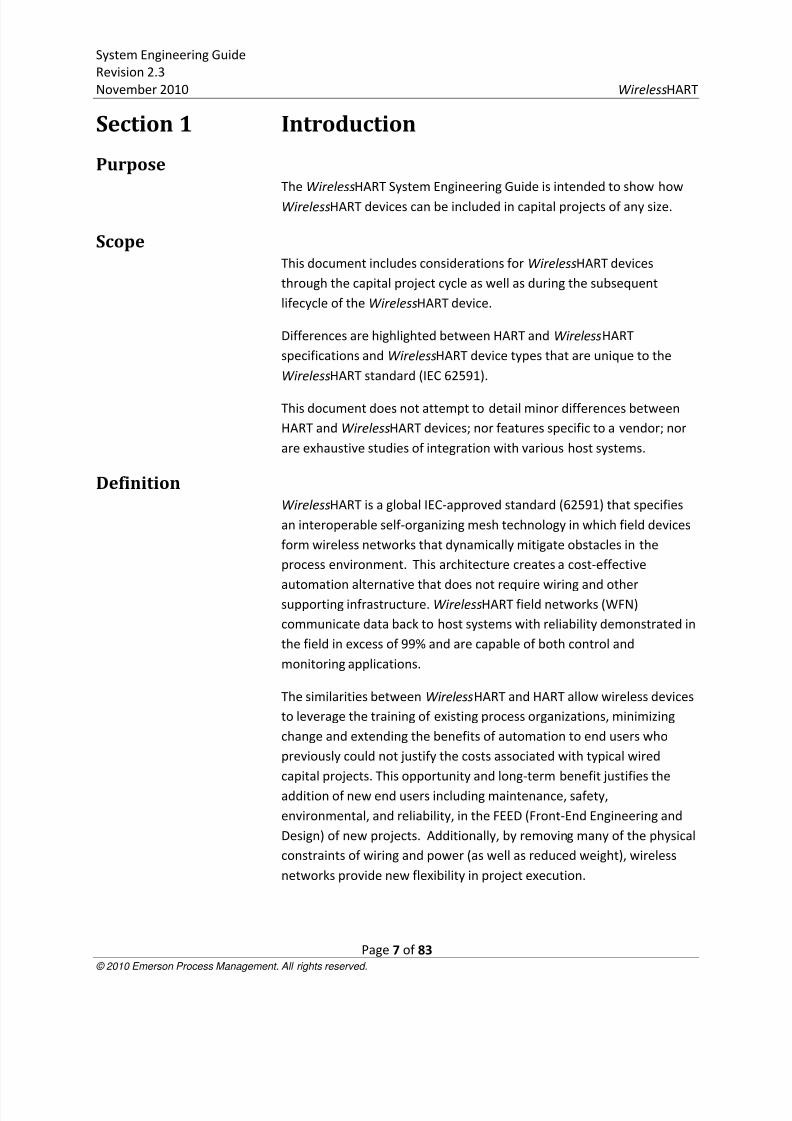
Section 1 Introduction
PurposeThe WirelessHART System Engineering Guide is intended to show how
WirelessHART devices can be included in capital projects of any size.
ScopeThis document includes considerations for WirelessHART devices
through the capital project cycle as well as during the subsequent
lifecycle of the WirelessHART device.
Differences are highlighted between HART and WirelessHART
specifications and WirelessHART device types that are unique to the
WirelessHART standard (IEC 62591).
This document does not attempt to detail minor differences between
HART and WirelessHART devices; nor features specific to a vendor; nor
are exhaustive studies of integration with various host systems.
DefinitionWirelessHART is a global IEC-approved standard (62591) that specifies
an interoperable self-organizing mesh technology in which field devices
form wireless networks that dynamically mitigate obstacles in the
process environment. This architecture creates a cost-effective
automation alternative that does not require wiring and othersupporting infrastructure. WirelessHART field networks (WFN)
communicate data back to host systems with reliability demonstrated in
the field in excess of 99% and are capable of both control and
monitoring applications.
The similarities between WirelessHART and HART allow wireless devices
to leverage the training of existing process organizations, minimizing
change and extending the benefits of automation to end users who
previously could not justify the costs associated with typical wired
capital projects. This opportunity and long-term benefit justifies the
addition of new end users including maintenance, safety,
environmental, and reliability, in the FEED (Front-End Engineering and
Design) of new projects. Additionally, by removing many of the physical
constraints of wiring and power (as well as reduced weight), wireless
networks provide new flexibility in project execution.
8/3/2019 Wireless Hart System Engineering Guide Rev 2.3
http://slidepdf.com/reader/full/wireless-hart-system-engineering-guide-rev-23 8/83
System Engineering Guide
Revision 2.3
November 2010 WirelessHART
Page 8 of 83 © 2010 Emerson Process Management. All rights reserved.
Section 2 Definitions
Terminology Definition
Ancillary
device
Any device that does not contain a measuring
sensor or output to the process for actuation.
Gateway Enables communication between wireless field
devices and host applications connected to an
Ethernet, Serial, or other existing plant
communications network; management of the
wireless field network; and management of
network security. Conceptually, the gateway is the
wireless version of marshalling panels and junction
boxes. The gateway functionality may also exist in
native WirelessHart I/O cards with field radios
Host System Any system accepting data produced by the
WirelessHART Field Network (WFN). This could be a
DCS, PLC, Historian, AMS, etc.
Join Key A 128 bit security key used to authenticate wireless
field devices when joining the network, includingencryption of the join request.
A common Join Key may be used among all devices
on a given network, or each device can have a
unique join key.
(Note: When displayed in hexadecimal format via a
browser or handheld, this results in a 32
hexadecimal field).
Network ID An integer between 0 and 65535 that distinguishesone WirelessHart network from another. Each
gateway at a facility or location should be
programmed with a unique Network ID. All
authenticated devices with the same Network ID
will communicate on the same network and
gateway.
8/3/2019 Wireless Hart System Engineering Guide Rev 2.3
http://slidepdf.com/reader/full/wireless-hart-system-engineering-guide-rev-23 9/83
System Engineering Guide
Revision 2.3
November 2010 WirelessHART
Page 9 of 83 © 2010 Emerson Process Management. All rights reserved.
Update Rate The user specified interval at which a wireless field
device will detect a measurement and transmit the
measurement to the gateway (i.e. sample rate).
The update rate has the largest impact on battery
life due to the powering of the device sensor.Update rate is independent of radio transmissions
required for mesh “hopping” via multiple devices to
transmit a measurement back to the gateway.
Wireless
Adapter
Enables an existing 4-20 mA, HART-enabled field
device to become wireless. Adapters allow the
existing 4-20 mA signal to operate parallel to the
digital wireless signal.
Wireless Field
Devices
Field device enabled with a WirelessHART radio and
software or an existing installed HART-enabled field
device with an attached WirelessHART adapter.
Wireless Field
Network
A self-organized network of wireless field devices
that automatically mitigate physical and RF
obstacles in the process environment to provide
necessary bandwidth for communicating process
and device information in a secure and reliable way.
Wireless
Repeater
Any wireless field device used to strengthen a
wireless field network (by adding additionalcommunication paths) or expand the total area
covered by a given mesh network.

8/3/2019 Wireless Hart System Engineering Guide Rev 2.3
http://slidepdf.com/reader/full/wireless-hart-system-engineering-guide-rev-23 10/83
System Engineering Guide
Revision 2.3
November 2010 WirelessHART
Page 10 of 83 © 2010 Emerson Process Management. All rights reserved.
AcronymsAbbreviation Description
AMS Asset Management System
CSSP Control Systems Security Program
DCS Distributed Control System
DD Device Descriptor
DSSS Direct-Sequence Spread Spectrum
FAT Factory Acceptance Test
FEED Front End Engineering and Design
HMI Human Machine Interface
LOS Line of Sight
NFPA National Fire Protection Association
PFD Process Flow Diagram
P&ID Piping and Instrument Design
PLC Programmable Logic Controller
RF Radio Frequency
RSSI Received Signal Strength Indicator
SIT Site Integration Test
SPI Serial Peripheral Interface
SPL Smart Plant Layout
TSMP Time Synchronized Mesh Protocol
TSSI Temporal Single-System Interpretation
UDF User Define Fields
WFN WirelessHART Field Network
8/3/2019 Wireless Hart System Engineering Guide Rev 2.3
http://slidepdf.com/reader/full/wireless-hart-system-engineering-guide-rev-23 11/83
System Engineering Guide
Revision 2.3
November 2010 WirelessHART
Page 11 of 83 © 2010 Emerson Process Management. All rights reserved.
Section 3 Project Concepts
Pre-FEEDDuring the Pre-FEED phase, consideration must be given to available
technologies and an assessment made on the applicability to the
specific project and application. It is during this Pre-FEED phase that
WirelessHart should be considered as a candidate technology, along
with other protocols including HART, Foundation Fieldbus, and Profibus.
During the Pre-FEED phase, spectrum approvals for the end-user and
any intermediary locations should be verified. Refer to Appendix D
Wireless Spectrum Governance for more details.
An integrated approach should be used for incorporating wireless into a
project. Wireless should be merged with the established procedures fora wired project. The key consideration is to use the right field device
technology for the right application and expand consideration for
possibly new end user communities during the FEED process.
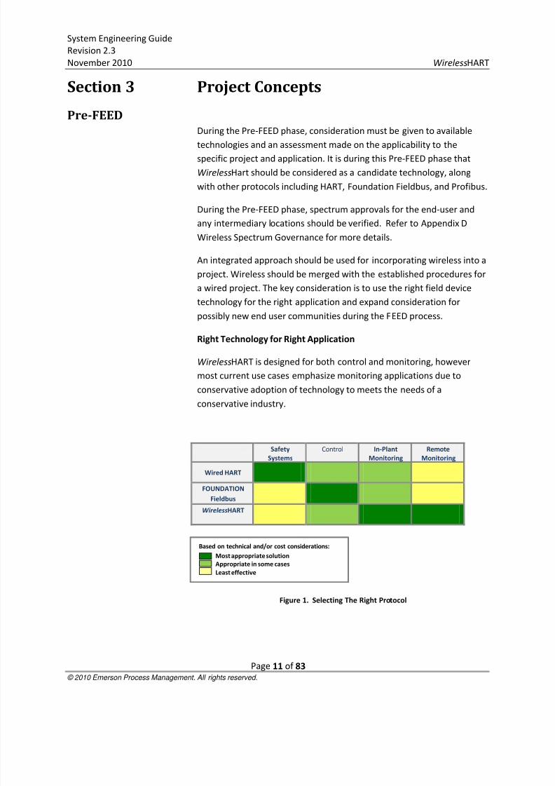
Right Technology for Right Application
WirelessHART is designed for both control and monitoring, however
most current use cases emphasize monitoring applications due to
conservative adoption of technology to meets the needs of a
conservative industry.
Safety
Systems
Control In-Plant
Monitoring
Remote
Monitoring
Wired HART
FOUNDATION
Fieldbus
WirelessHART
Figure 1. Selecting The Right Protocol
Based on technical and/or cost considerations:
Most appropriate solution
Appropriate in some cases
Least effective

8/3/2019 Wireless Hart System Engineering Guide Rev 2.3
http://slidepdf.com/reader/full/wireless-hart-system-engineering-guide-rev-23 12/83

8/3/2019 Wireless Hart System Engineering Guide Rev 2.3
http://slidepdf.com/reader/full/wireless-hart-system-engineering-guide-rev-23 13/83
System Engineering Guide
Revision 2.3
November 2010 WirelessHART
Page 13 of 83 © 2010 Emerson Process Management. All rights reserved.
FEEDKey deliverables exist for wireless in the FEED, for example: cost
estimating, design guidelines, and specifications.
Cost Estimation
Vendors of WirelessHART field devices may have cost calculators and
capital project studies that can be referenced and compared to support
the cost justification of wireless into a project or an all wireless project.
For a large capital project, wireless can reduce capital costs by switching
wired monitoring points to wireless.
Design Engineers should assess and incorporate the following factors in
their project cost estimating calculation model:
Reduced engineering costs (including drawing and
documentation, as well as FAT)
Reduced labor (field installation, commissioning, supervision)
Reduced materials (terminations, junction boxes, wiring, cable
trays/conduit/trunking, power supplies, and control system
components)
I/O capacity management (each WirelessHart gateway
essentially provides spare I/O capacity)
Design Guidelines for WirelessHART
During the FEED, all project stakeholders should be made aware of the
capability and benefits of WirelessHART so that design engineers can
identify potential candidate applications. The project should develop a
wireless design guideline that must be circulated to all project
stakeholders.
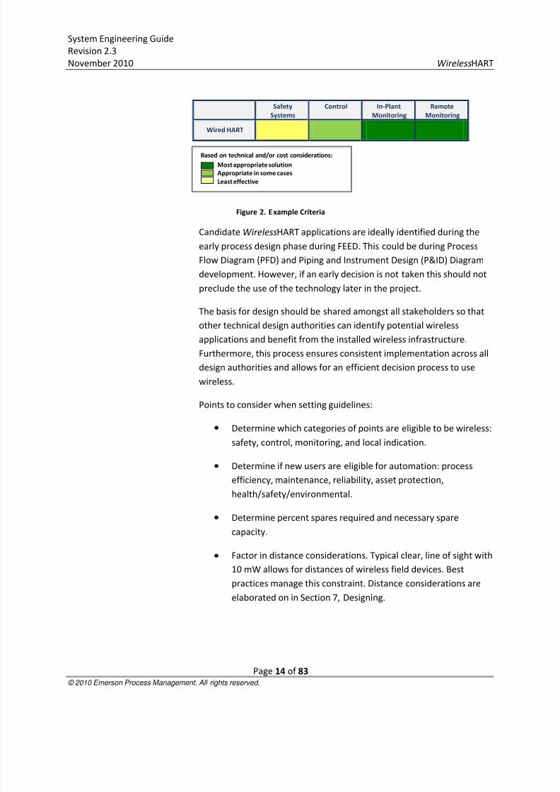
For example the process design engineer can use a set of criteria such as
the simplified table in Figure 2 to identify candidate wireless
applications.
8/3/2019 Wireless Hart System Engineering Guide Rev 2.3
http://slidepdf.com/reader/full/wireless-hart-system-engineering-guide-rev-23 14/83
System Engineering Guide
Revision 2.3
November 2010 WirelessHART
Page 14 of 83 © 2010 Emerson Process Management. All rights reserved.
Safety
Systems
Control In-Plant
Monitoring
Remote
Monitoring
Wired HART
Figure 2. Example Criteria
Candidate WirelessHART applications are ideally identified during the
early process design phase during FEED. This could be during Process
Flow Diagram (PFD) and Piping and Instrument Design (P&ID) Diagram
development. However, if an early decision is not taken this should notpreclude the use of the technology later in the project.
The basis for design should be shared amongst all stakeholders so that
other technical design authorities can identify potential wireless
applications and benefit from the installed wireless infrastructure.
Furthermore, this process ensures consistent implementation across all
design authorities and allows for an efficient decision process to use
wireless.
Points to consider when setting guidelines:
Determine which categories of points are eligible to be wireless:
safety, control, monitoring, and local indication.
Determine if new users are eligible for automation: process
efficiency, maintenance, reliability, asset protection,
health/safety/environmental.
Determine percent spares required and necessary spare
capacity.
Factor in distance considerations. Typical clear, line of sight with10 mW allows for distances of wireless field devices. Best
practices manage this constraint. Distance considerations are
elaborated on in Section 7, Designing.
Based on technical and/or cost considerations:
Most appropriate solution
Appropriate in some cases
Least effective

8/3/2019 Wireless Hart System Engineering Guide Rev 2.3
http://slidepdf.com/reader/full/wireless-hart-system-engineering-guide-rev-23 15/83
System Engineering Guide
Revision 2.3
November 2010 WirelessHART
Page 15 of 83 © 2010 Emerson Process Management. All rights reserved.
Specifications
Specifications for WirelessHART field devices are 90% the same as wired
HART devices. See Appendix B WirelessHART vs. Wired Hart Comparison
for key differences. HART instrumentation specifications are thefoundation for WirelessHART specifications. The fundamental
differences with regards to the ISA-20 specifications are output signal,
power supply, update rate, protection type/enclosure. Specifications
not included in this short list are either included with the IEC 62591
WirelessHART standard, small deviations from HART that require
optional attention for the specification process, or are unique to a field
device vendor.
Figure 3 is a comparison of fundamental differences in the
specifications1:
Specification Field Typical HART Specification Typical WirelessHART Specification
Output Signal 4-20 mA HART IEC 62591 WirelessHART
Power Supply 24V DC Loop Powered Intrinsically Safe Battery2
Update rate 1 second 1 second to 60 minutes
Protection Type/Enclosure Explosion Proof Intrinsically Safe2
Figure 3. Key Differences Between Wired and WirelessHART
IEC 62591 WirelessHART is an international standard for wireless
process devices. The standard includes advanced provisions for security,
protocol, and other features and therefore specification of such
attributes covered in the standard are not necessary.
Appendix A provides example specifications for a WirelessHART gateway
and wireless adapter that can be generically specified as
transceivers/receivers.
Detailed EngineeringDuring the detailed engineering phase of a project, the engineer must
account for WirelessHART devices per the guidelines established in the
FEED, add wireless specific fields to the project database, and conduct
wireless field network design procedures to ensure best practices areimplemented.
Sort the Points
1Values in table are typical and representative, but not mandatory.
2The trend with wireless field device vendors has been intrinsically safe protection, with explosion proof an
option. This potential difference is noted in the best interest of the audience so as to do thorough due diligence.
8/3/2019 Wireless Hart System Engineering Guide Rev 2.3
http://slidepdf.com/reader/full/wireless-hart-system-engineering-guide-rev-23 16/83
System Engineering Guide
Revision 2.3
November 2010 WirelessHART
Page 16 of 83 © 2010 Emerson Process Management. All rights reserved.
From the wireless guidelines established in the FEED, the engineer
should do a sort of all points in the project database to identify which
are eligible to be wireless. For example, if monitoring is deemed to be
an eligible category, these points should be sorted from the control and
other points. Afterwards, further requirements of the field devices canbe applied. For example, some control points may be excluded from
wireless eligibility because the required update rate exceeds either the
desired life of the battery or the capability of the field device.
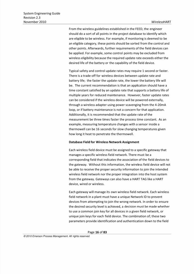
Typical safety and control update rates may require 1 second or faster.
There is a trade-off for wireless devices between update rate and
battery life; the faster the update rate, the lower the battery life will
be. The current recommendation is that an application should have a
time constant satisfied by an update rate that supports a battery life of
multiple years for reduced maintenance. However, faster update ratescan be considered if the wireless device will be powered externally,
through a wireless adapter using power scavenging from the 4-20mA
loop, or if battery maintenance is not a concern for that application.
Additionally, it is recommended that the update rate of the
measurement be three times faster the process time constant. As an
example, measuring temperature changes with a sensor inside a
thermowell can be 16 seconds for slow changing temperatures given
how long it heat to penetrate the thermowell.
Database Field for Wireless Network Assignment
Each wireless field device must be assigned to a specific gateway that
manages a specific wireless field network. There must be a
corresponding field that indicates the association of the field devices to
the gateway. Without this information, the wireless field device will not
be able to receive the proper security information to join the intended
wireless field network nor the proper integration into the host system
from the gateway. Gateways can also have a HART TAG like a HART
device, wired or wireless.
Each gateway will manage its own wireless field network. Each wirelessfield network in a plant must have a unique Network ID to prevent
devices from attempting to join the wrong network. In order to ensure
the desired security level is achieved, a decision must be made whether
to use a common join key for all devices in a given field network, or
unique join keys for each field device. The combination of; these two
parameters provide identification and authentication down to the field
8/3/2019 Wireless Hart System Engineering Guide Rev 2.3
http://slidepdf.com/reader/full/wireless-hart-system-engineering-guide-rev-23 17/83
System Engineering Guide
Revision 2.3
November 2010 WirelessHART
Page 17 of 83 © 2010 Emerson Process Management. All rights reserved.
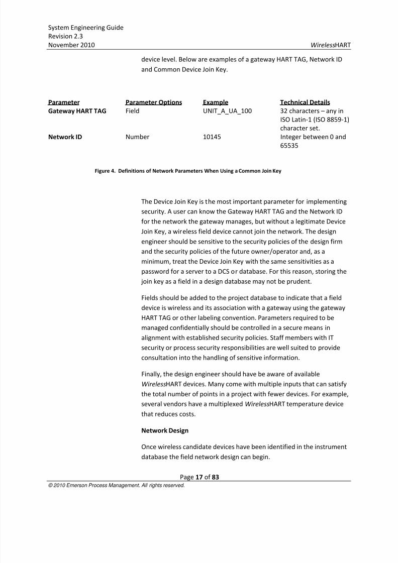
device level. Below are examples of a gateway HART TAG, Network ID
and Common Device Join Key.
Parameter Parameter Options Example Technical Details
Gateway HART TAG Field UNIT_A_UA_100 32 characters – any in
ISO Latin-1 (ISO 8859-1)
character set.
Network ID Number 10145 Integer between 0 and
65535
Figure 4. Definitions of Network Parameters When Using a Common Join Key
The Device Join Key is the most important parameter for implementing
security. A user can know the Gateway HART TAG and the Network ID
for the network the gateway manages, but without a legitimate Device
Join Key, a wireless field device cannot join the network. The design
engineer should be sensitive to the security policies of the design firm
and the security policies of the future owner/operator and, as a
minimum, treat the Device Join Key with the same sensitivities as a
password for a server to a DCS or database. For this reason, storing the
join key as a field in a design database may not be prudent.
Fields should be added to the project database to indicate that a field
device is wireless and its association with a gateway using the gateway
HART TAG or other labeling convention. Parameters required to be
managed confidentially should be controlled in a secure means in
alignment with established security policies. Staff members with IT
security or process security responsibilities are well suited to provide
consultation into the handling of sensitive information.
Finally, the design engineer should have be aware of available
WirelessHART devices. Many come with multiple inputs that can satisfy
the total number of points in a project with fewer devices. For example,several vendors have a multiplexed WirelessHART temperature device
that reduces costs.
Network Design
Once wireless candidate devices have been identified in the instrument
database the field network design can begin.
8/3/2019 Wireless Hart System Engineering Guide Rev 2.3
http://slidepdf.com/reader/full/wireless-hart-system-engineering-guide-rev-23 18/83
System Engineering Guide
Revision 2.3
November 2010 WirelessHART
Page 18 of 83 © 2010 Emerson Process Management. All rights reserved.
Ideally wireless points should be organized by process unit and by
subsection of process unit as typically depicted in a master drawing.
This information can be used to determine the number of gateways
required. Additional gateways can be added to ensure spare I/O
capacity per guidelines or other project requirements. From here, thegateways can be logically distributed throughout the process unit like
marshalling panels. Wireless field devices can then be assigned
according to which gateway is closest or by which gateway is assigned
to the process unit subsection in which the field devices reside. Once
this is complete, network design best practices can be checked to
ensure the network will be reliable. This will be covered in detail in the 0
WirelessHART Field Network Design Guidelines.
Drawings should be created per existing standards. In most instances, a
wireless field device is treated identically to a wired HART device. Mostdrawings do not indicate wires or the type of protocol, thus nothing
unique needs to be done for wireless field devices. 0 Ancillary Device
Requirements documents examples specific to wireless field devices and
devices unique to WirelessHART such as gateways and wireless
adapters. Fundamentally, it will be up to the design engineer to adhere
to or provide a consistent convention that meets the needs of the
contractor and the owner operator as is true for wired HART projects.
Existing HMI (human-machine interface) design guidelines for
integration also apply to wireless no change is required.
Factory Acceptance Test For Factory Acceptance Tests, it will be necessary to establish a
connection between the Gateway and the Host Systems. WirelessHART
gateways typically have standard output protocols that either directly or
indirectly can connect to any host system. The design team should keep
a library of these integration options for reference.
InstallationIn general, WirelessHART device are installed identically to wired HART
devices. Emphasis should always be placed on making the best possible
process connection for accurate measurement. The self-organizing
mesh technology in WirelessHART enables wireless field devices to self-
route through the process environment and reroute when the
environment changes. Always consult the manual of the WirelessHART
device for special considerations. This is covered in detail in 0
WirelessHart Field Network Design Guidelines.
8/3/2019 Wireless Hart System Engineering Guide Rev 2.3
http://slidepdf.com/reader/full/wireless-hart-system-engineering-guide-rev-23 19/83
8/3/2019 Wireless Hart System Engineering Guide Rev 2.3
http://slidepdf.com/reader/full/wireless-hart-system-engineering-guide-rev-23 20/83
System Engineering Guide
Revision 2.3
November 2010 WirelessHART
Page 20 of 83 © 2010 Emerson Process Management. All rights reserved.
Section 4 Document Requirements
DrawingsEvery project will require the establishment of local standards for
implementing consistent documentation.
See 0 Documenting in Integraph SPI 2009 for a complete treatment of
documentation.
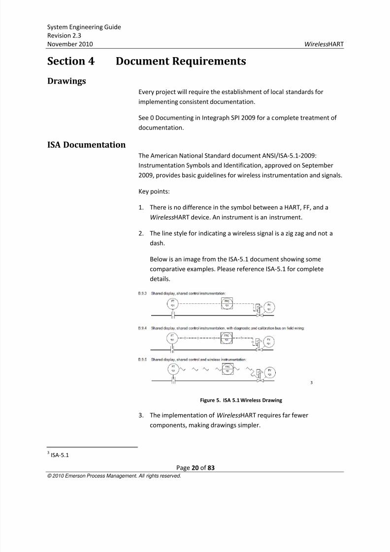
ISA DocumentationThe American National Standard document ANSI/ISA-5.1-2009:
Instrumentation Symbols and Identification, approved on September
2009, provides basic guidelines for wireless instrumentation and signals.
Key points:
1. There is no difference in the symbol between a HART, FF, and a
WirelessHART device. An instrument is an instrument.
2. The line style for indicating a wireless signal is a zig zag and not a
dash.
Below is an image from the ISA-5.1 document showing some
comparative examples. Please reference ISA-5.1 for complete
details.
3
Figure 5. ISA 5.1 Wireless Drawing
3. The implementation of WirelessHART requires far fewer
components, making drawings simpler.
3ISA-5.1

8/3/2019 Wireless Hart System Engineering Guide Rev 2.3
http://slidepdf.com/reader/full/wireless-hart-system-engineering-guide-rev-23 21/83
System Engineering Guide
Revision 2.3
November 2010 WirelessHART
Page 21 of 83 © 2010 Emerson Process Management. All rights reserved.
Control NarrativeDefine in the FEED phase and ensure this is implemented with design
guidelines.
Instrument Index/DatabaseSee 0 Documenting in Integraph SPI 2009 for recommendations for
additional fields not typically included in wired HART specifications.
Instrument Data SheetsUse standard data sheets created for wired HART devices. Update the
following fields to reflect WirelessHART:
Specification Field Typical Value
Update rate 1, 2,4, 8, 16, 32, 64+
Power Supply Intrinsically safe, field replaceable battery
Communication Type IEC 62591 WirelessHARTFigure 6. WirelessHart Specifications For Instrument Data Sheets
No special ISA or other specification sheets are required as the same
sheets can be used to specify HART, FOUNDATION Fieldbus, or
WirelessHART. See Appendix A for a specification sheet example for a
WirelessHART gateway.
Material RequisitionsGiven the need for security and RF emissions, vendors must acquire
approvals for importation to the country of end-use for compliance withlocal spectrum regulation and encryption regulation. The vendor can
verify whether importation compliance exists for any given country.
The batteries are commonly made using a high energy compound using
Lithium Thionyl Chloride. The Material Safety Data Sheet or equivalent
should always be available as well as awareness of any shipping
restriction, particularly for passenger aircraft.
Manufacturer DocumentationEvery WirelessHART device should have the proper documentation,
including manual, as would be expected with a wired HART device.
Project Management Subcontractor Scope Management
Wireless enables simplified sub contractor scope management.
Packages can be easily tested and commissioned separately, requiring
only minimal integration and testing to occur. Additionally the sub
contractors will also benefit from fewer components and engineering.

8/3/2019 Wireless Hart System Engineering Guide Rev 2.3
http://slidepdf.com/reader/full/wireless-hart-system-engineering-guide-rev-23 22/83
System Engineering Guide
Revision 2.3
November 2010 WirelessHART
Page 22 of 83 © 2010 Emerson Process Management. All rights reserved.
Tender contracts should be amended to recognize reduced complexity
and eliminated work.
Project Scheduling
1. Review schedules to recognize:
Limited infrastructure installation and hence reduced material
and installation scope
Remove some electrical and instrumentation checkout
processes
2. Amend contracts to reflect simplified installation handover
processes
3. Simplify installation schedule management
4. Reduce material coordination management and simplified
construction schedule
Eliminated scheduling and expediting associated with
marshalling cabinets5. Schedule should reflect eliminated activities and simplified FAT, SAT
and SIT (site integration test) on areas where wireless has been
extensively deployed
Responsibility and Skills Matrix
Amend Roles and Responsibility matrix to reflect
reduced/eliminated responsibilities
Ensure engagement of all project stakeholders/sub-contractor so
that wireless can be applied efficiently to improve schedule and
material costs
Managing Project Variations
For project change orders and other late design changes, wireless
should be considered as the primary solution unless other design
considerations exist. Using wireless will result in the fewest changes to
the documentation, I/O layout and other detailed design as well as
faster commissioning.

8/3/2019 Wireless Hart System Engineering Guide Rev 2.3
http://slidepdf.com/reader/full/wireless-hart-system-engineering-guide-rev-23 23/83
System Engineering Guide
Revision 2.3
November 2010 WirelessHART
Page 23 of 83 © 2010 Emerson Process Management. All rights reserved.
Section 5 Field Device Requirements
Support for WirelessHART FunctionalityAll WirelessHART devices support methods to allow remote access to
device configuration, backwards compatibility with existing field
communicators, full implementation of WirelessHART security
provisions, and WirelessHART interoperability.
Device DiagnosticsHART Diagnostics
WirelessHART devices contain similar or a subset all of the diagnostics of
wired HART devices. Expect configurable alarms and alerts for both the
process and the device. Diagnostics information should be available
through HART commands as well as accessible through Device
Descriptions (DD) either locally through a field communicator or
remotely using asset management software.
Wireless Field Device Network Diagnostics
Every WirelessHART field device should have diagnostics that indicate if
a device is connected to a network or not.
Wireless Field Device Power Diagnostics
Wireless field devices will have one of three power options: battery,energy harvesting (including solar), or line power. Batteries will have a
life determined by the update rate of the wireless field device, network
routing for other wireless field devices, and efficiencies of the sensor
and electronics. Typically, the primary consumer of power is the
wireless field device sensor and electronics; using the WirelessHART
radio or acting as a repeater/relay for other WirelessHART field devices
requires minimal power. Wireless field devices report their battery
voltage and have integrated low voltage alarms such that the user can
either schedule maintenance or take a corrective action.
Gateway Network Diagnostics
Gateway network diagnostics should indicate whether field devices are
connected and functioning properly, and if devices are missing from the
network. In order to be connected properly, proper bandwidth must be
allocated based on the update rate of the device. A device connected
but with service denied may indicate a device has an update rate that is

8/3/2019 Wireless Hart System Engineering Guide Rev 2.3
http://slidepdf.com/reader/full/wireless-hart-system-engineering-guide-rev-23 24/83
System Engineering Guide
Revision 2.3
November 2010 WirelessHART
Page 24 of 83 © 2010 Emerson Process Management. All rights reserved.
too fast for the network capability or the network conditions. With
gateways capable of holding 100 devices or more, clear indication of
device availability is crucial.
Additionally, gateways should be able to detect, regardless of hostsystem integration, the connectedness of a wireless field device. This
information should be continually updated and indicate if a device is not
connected for network or device reasons. Simple device states should
be made available for integration into the host system regardless of
output protocol from the gateway to indicate online/offline status.
Field Device PowerWireless field devices will have one of three power options: battery,
energy harvesting (including solar), or line power and there may be
several options with in each category.
Batteries
The most common will be the use of a battery for low power field
devices due to ease of deployment. Most vendors will use battery cells
incorporating Lithium Thionyl Chloride chemistry since it has the highest
energy density that is commercially viable. Although typical cells look
like battery cells for consumer electronics, precautions should be taken
to ensure batteries are safely introduced into the process environment.
Refer to vendor documentation for safe handling practices.
Below are requirements for batteries:
Batteries cells should be assembled by a manufacturer into a
battery module to ensure safety.
Battery module should prevent a depleted cell being introduced
in circuit with a charged cell, which can cause unintended
electrical currents and heat.
Battery module should provide ease of replacement. Battery
replacement should take minimal time and training.
Battery module should be intrinsically safe and not require
removal of the wireless field device for replacement.
Battery module should prevent intended and unintended short-
circuiting that could lead to heat or spark.

8/3/2019 Wireless Hart System Engineering Guide Rev 2.3
http://slidepdf.com/reader/full/wireless-hart-system-engineering-guide-rev-23 25/83
System Engineering Guide
Revision 2.3
November 2010 WirelessHART
Page 25 of 83 © 2010 Emerson Process Management. All rights reserved.
Battery module should be designed for the process
environment with mechanical properties that provide drop
connection and operation over normal process temperatures
expected for devices.
Battery modules should come with necessary Material Safety
Data Sheets (or equivalent) and warnings and be disposable per
local governmental regulation.
Battery module should not be capable of connecting to
consumer electronics or non-designed applications to prevent a
high-capacity supply from being connected to incompatible
electrical systems.
Battery modules should be applicable to several WirelessHART
field devices to maximize inventory management efficiencies in
the local warehouse for spare parts.
The design engineers of the wireless field network and end users should
use update rates that maximize the life of the battery module and
minimize maintenance.
Energy Harvesting
Vendors may provide energy harvesting options as alternatives to
batteries that may include solar, thermal, vibration, and wind solutions.
Current energy conversion techniques for thermal and vibration are
relatively inefficient. In many cases, energy harvesting solutions also
utilize rechargeable batteries to maintain constant supply. Today’s
rechargeable batteries have a life expectancy of only several years
during which they can maintain a full charge. This life expectancy is
often shorter than that of non-rechargeable Lithium Thionyl Chloride
batteries. Adoption of energy harvesting is likely to increase as vendors
reduce the voltage and power consumption of wireless field devices and
technical difficulties are removed from harvesting technologies. The
current, most viable solution is solar, which has the difficulty of
maintaining incidence of light on solar arrays as seasons change along
with the tilt of the earth relative to the sun. Additionally, difficulties
have been experienced even in desert environments with an abundance
of light due the need to keep the solar panels clean for maximum
energy conversion.
Below are requirements for energy harvesters:

8/3/2019 Wireless Hart System Engineering Guide Rev 2.3
http://slidepdf.com/reader/full/wireless-hart-system-engineering-guide-rev-23 26/83
System Engineering Guide
Revision 2.3
November 2010 WirelessHART
Page 26 of 83 © 2010 Emerson Process Management. All rights reserved.
Wireless field device should have a design connection for
energy harvesting device.
Energy harvesting device should have means for providing
multiple days of power in the event the energy source isdiscontinued for several days.
Energy harvesting device should be mounted such that it is not
negatively impacted by changes in the season.
Energy device should be intrinsically safe and incapable of
generating heat or short circuits like the battery module.
Energy harvester should have the means for the user to know
the state of the device.
Energy harvester should be able to be locked out to prevent
uncontrolled energy production.
Line Power
In some ways, a line power option is counter-intuitive for a wireless
device. However, some wireless adapters may harvest power off of 4-20
mA loop power devices, and some applications with high power sensors
may need to be wireless from a communications standpoint yet require
more power than a battery or energy harvester can provide.
Below are the requirements for a line power option:
Wireless adapters harvesting power from the 4-20 mA loop of
the wired device should not affect the control signal during
normal operation or failure mode.
Line powered wireless devices not designed specifically for 4-20
mA loops should not require pristine power supplies. They
should be capable of a wide range of voltages and not require
filter of noise or special conditioners for proper operation.
Field Device SecuritySecurity is a new consideration that is driven by an increased focus on
the protection of critical infrastructure, particularly by governments and
other compliance authorities.
Below are the requirements for wireless field device security:

8/3/2019 Wireless Hart System Engineering Guide Rev 2.3
http://slidepdf.com/reader/full/wireless-hart-system-engineering-guide-rev-23 27/83
System Engineering Guide
Revision 2.3
November 2010 WirelessHART
Page 27 of 83 © 2010 Emerson Process Management. All rights reserved.
Wireless devices should be compliant with all WirelessHART
security provisions including correct usage of Network ID and
Device Join Key.
The user or unintended user should not be able to physically ordigitally read the Device Join Key from the wireless device. The
Device Join Key(s) should be treated as confidential and subject
to the requirements of any local security policy. For example, a
technician with low level security clearance could obtain the
Network ID and common Join Key from a gateway administrator
authenticated by the gateway.
The wireless device should be receptive to security changes
initiated by the gateway, including Network ID, Device Join Key,
and the network, session, and broadcast keys that validate
packets sent through the network and prevent tampering and
eavesdropping.
The gateway and any management program connected to the
WirelessHART network through the gateway should protect all
security parameters according to a local security policy.
Approvals
Every WirelessHART device must have the appropriate hazardous areaapproval to meet the conditions of the process environment as well at
the appropriate spectrum and encryption approvals. Spectrum and
encryption of wireless signals are regulated by government agencies,
such as the FCC in the United States. Typically, verifying with the
WirelessHART device manufacturer that the device has proper approval
for importation to the country of usage is sufficient. Spectrum and
encryption approval are a procurement issue and do not represent a
design parameter like a hazardous area approval.
AccessibilityWirelessHART devices are subject to the same mechanical and electrical
specifications as wired HART devices as they will operate in the same
process environments.

8/3/2019 Wireless Hart System Engineering Guide Rev 2.3
http://slidepdf.com/reader/full/wireless-hart-system-engineering-guide-rev-23 28/83
System Engineering Guide
Revision 2.3
November 2010 WirelessHART
Page 28 of 83 © 2010 Emerson Process Management. All rights reserved.
Below are general requirements for WirelessHART field devices:
WirelessHART devices shall be locally accessible with HART field
communicators that support wired and WirelessHART devices.
WirelessHART devices shall be manageable with remote asset
management systems that access the WirelessHART device via
the gateway and through the WirelessHART network.
WirelessHART adapters shall extend the benefits of a
WirelessHART network to wired HART devices that may or may
not be operated on a 4-20 mA loop.
8/3/2019 Wireless Hart System Engineering Guide Rev 2.3
http://slidepdf.com/reader/full/wireless-hart-system-engineering-guide-rev-23 29/83
System Engineering Guide
Revision 2.3
November 2010 WirelessHART
Page 29 of 83 © 2010 Emerson Process Management. All rights reserved.
Section 6 Ancillary Device RequirementsAn ancillary device is defined as any device that does not contain a
measuring sensor or output to the process for actuation. These include
wireless gateways, local indicators, wireless repeaters and/or
WirelessHART adapters.
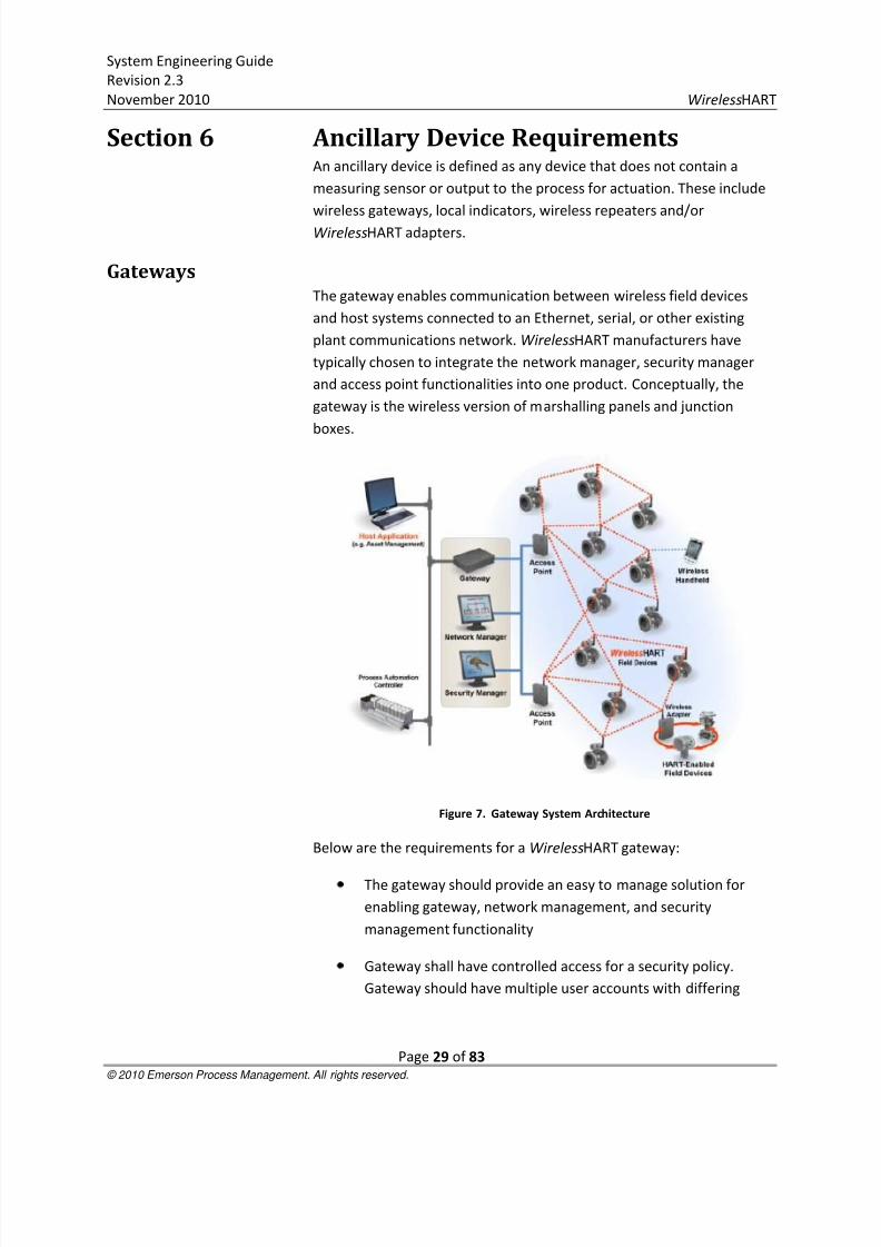
GatewaysThe gateway enables communication between wireless field devices
and host systems connected to an Ethernet, serial, or other existing
plant communications network. WirelessHART manufacturers have
typically chosen to integrate the network manager, security manager
and access point functionalities into one product. Conceptually, the
gateway is the wireless version of marshalling panels and junction
boxes.
Figure 7. Gateway System Architecture
Below are the requirements for a WirelessHART gateway:
The gateway should provide an easy to manage solution for
enabling gateway, network management, and security
management functionality
Gateway shall have controlled access for a security policy.
Gateway should have multiple user accounts with differing

8/3/2019 Wireless Hart System Engineering Guide Rev 2.3
http://slidepdf.com/reader/full/wireless-hart-system-engineering-guide-rev-23 30/83
System Engineering Guide
Revision 2.3
November 2010 WirelessHART
Page 30 of 83 © 2010 Emerson Process Management. All rights reserved.
access to critical security and configuration parameters such
that there can be a sole network administrator.
Gateway shall have multiple output protocols to ensure
integration to a range of host applications. In any given processfacility, there can several types of DCS, PLC, and historians
requiring unique protocols. Multiple output protocols allow
convenient connectivity with a standard gateway.
The gateway shall support multiple connections and, in effect,
act like a server. Typical WirelessHART applications require data
to be sent to multiple host applications in order to provide data
to multiple end users.
The gateway shall support the secure transfer of all protocols
over an Ethernet connection through an encryption process.
Gateway shall be interoperable and support the network
management of WirelessHART devices from multiple vendors.
Wireless RepeatersThere are no special requirements for a WirelessHART repeater. If a
repeater is a WirelessHART device with a configurable update rate, then
minimizing the update rate shall maximize the life of the battery module
without impacting the network reliability.
If a vendor chooses to develop a WirelessHART device for the specific
purpose of acting as a repeater, then that repeating device shall be
manageable like any other WirelessHART device and subject to all the
specifications of a WirelessHART device. WirelessHART adapters can be
used effectively as repeaters if local power or a wired HART device is
available.
WirelessHART AdaptersWirelessHART adapters connect to wired HART devices that are not
inherently wireless and provide parallel output signals through the 4-20
mA loop and the WirelessHART field network. There are four main use
cases for WirelessHART adapters:
Access HART diagnostics that are not accessible due to
limitations of the host system which may prevent the HART
signal from passing over the 4-20 mA loop.
8/3/2019 Wireless Hart System Engineering Guide Rev 2.3
http://slidepdf.com/reader/full/wireless-hart-system-engineering-guide-rev-23 31/83
System Engineering Guide
Revision 2.3
November 2010 WirelessHART
Page 31 of 83 © 2010 Emerson Process Management. All rights reserved.
Provide wireless communications for HART devices which are
not natively wireless.
Enable device information to be accessed by multiple users who
may not have direct access to the control system. In thisscenario, the wired signal is sent to the control room while the
wireless signal could be accessed in a separate office by
maintenance, reliability, or other personnel.
Act as a wireless repeater.
Below are the WirelessHART Adapter specifications:
Adapter should not affect the 4-20 mA signals under normal
operation.
Adapter should not affect the 4-20 mA under failure conditions.
Adapter should operate like any other WirelessHART field
device in the WirelessHART field network.
Adapter should have a HART Tag.
Adapter should pass through the wired HART device process
variable as well as remote access for configuration and
calibration.
8/3/2019 Wireless Hart System Engineering Guide Rev 2.3
http://slidepdf.com/reader/full/wireless-hart-system-engineering-guide-rev-23 32/83
System Engineering Guide
Revision 2.3
November 2010 WirelessHART
Page 32 of 83 © 2010 Emerson Process Management. All rights reserved.
Section 7 WirelessHART Field Network
Design GuidelinesThe WirelessHART network specification enables a successful and
scalable architecture. Contrary to legacy systems and point-to-point
wireless networks, WirelessHART is a truly scalable automation
technology that gets more robust as more devices are added to an
existing network. Design guidelines support the deployment of small
networks, less than 10 WirelessHART devices, as well as segmenting
multiple networks when a process facility requires far larger numbers of
WirelessHART devices.
This section also includes additional recommendations to support the
long-term, sustainable adoption of wireless applications including not
just: WirelessHART but, Wi-Fi, Wi-Max and more.
The best practices for network design are generally applicable for
networks operating with mix of WirelessHART devices with a variety of
update rates from 4 seconds to 3600 seconds (60 minutes). Please see
the section Designing for Control for additional considerations when
including 1 second update rates.
A site survey is not normally required or even possible in the case of a
Greenfield site. For an overview on spectrum usage refer to Appendix D
Wireless Spectrum Governance.
Wireless Project OverviewAn extensive summary of the project overview was previously discussed
in 0 Project Concepts.
Because WirelessHART is built upon the HART standard, there are
minimum differences between the usages of the devices. The minimal
need for wires also means there are fewer engineering details to
manage and fewer engineering parameters to introduce. This section
provides a thorough discussion of WirelessHART Field Network Design.
The following can be applied to small projects requiring a single gateway
or a large project requiring several gateways.
8/3/2019 Wireless Hart System Engineering Guide Rev 2.3
http://slidepdf.com/reader/full/wireless-hart-system-engineering-guide-rev-23 33/83
System Engineering Guide
Revision 2.3
November 2010 WirelessHART
Page 33 of 83 © 2010 Emerson Process Management. All rights reserved.
WirelessHART Field Network DesignThere are three key steps for designing a network:
Scope – Decide if you need to divide wireless field networks by
process unit or subsection of a process unit.
Design – Apply design rules to ensure optimum connectivity.
Fortify – Fix any potential weaknesses in the network design.
The three basic steps apply for all process environments in all industries,
although the context may vary slightly depending on the physical
structure of the environment. The basic steps also apply regardless of
the vendor of the WirelessHART device. Since WirelessHART networks
become stronger the more devices are added, the Scope step is the
most critical for high density applications.
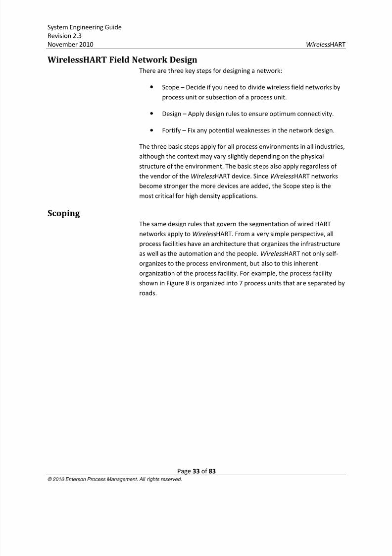
ScopingThe same design rules that govern the segmentation of wired HART
networks apply to WirelessHART. From a very simple perspective, all
process facilities have an architecture that organizes the infrastructure
as well as the automation and the people. WirelessHART not only self-
organizes to the process environment, but also to this inherent
organization of the process facility. For example, the process facility
shown in Figure 8 is organized into 7 process units that are separated by
roads.
8/3/2019 Wireless Hart System Engineering Guide Rev 2.3
http://slidepdf.com/reader/full/wireless-hart-system-engineering-guide-rev-23 34/83
System Engineering Guide
Revision 2.3
November 2010 WirelessHART
Page 34 of 83 © 2010 Emerson Process Management. All rights reserved.
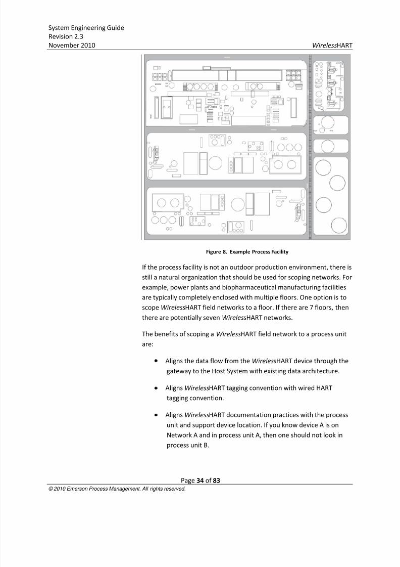
Figure 8. Example Process Facility
If the process facility is not an outdoor production environment, there is
still a natural organization that should be used for scoping networks. For
example, power plants and biopharmaceutical manufacturing facilities
are typically completely enclosed with multiple floors. One option is toscope WirelessHART field networks to a floor. If there are 7 floors, then
there are potentially seven WirelessHART networks.
The benefits of scoping a WirelessHART field network to a process unit
are:
Aligns the data flow from the WirelessHART device through the
gateway to the Host System with existing data architecture.
Aligns WirelessHART tagging convention with wired HART
tagging convention.
Aligns WirelessHART documentation practices with the process
unit and support device location. If you know device A is on
Network A and in process unit A, then one should not look in
process unit B.
8/3/2019 Wireless Hart System Engineering Guide Rev 2.3
http://slidepdf.com/reader/full/wireless-hart-system-engineering-guide-rev-23 35/83
System Engineering Guide
Revision 2.3
November 2010 WirelessHART
Page 35 of 83 © 2010 Emerson Process Management. All rights reserved.
Aligns work processes of managing WirelessHART device
lifecycles with wired HART life cycles including organizational
responsibilities.
Sets reasonable expectations for range between WirelessHARTdevices. Most process units are not more than a few hundred
feet (<0.2km) by a few hundred feet (<0.2km).
While scoping, the design engineer should factor in considerations for
spare capacity. At a minimum, each process unit should have its own
gateway with spare capacity for problem solving in real time. If a project
is small and application focused, then typically a single gateway is
required if the total number of points is less than the capacity of the
gateway. If the project is large, below is the process of determining the
total number of gateways and modifying the scope of a network.
1. Filter the points by process unit and determine how many points
are in each process unit so that the WirelessHART networks can be
segmented by process unit. For example, out of 700 points, let’s
assume process unit A has 154 wireless points requiring 154
WirelessHART devices. We need to determine how many gateways
are needed. Note that some WirelessHART devices support more
than 1 wireless point and so there may be instances when fewer
devices are required to satisfy the number of measurement points.
A key example is a WirelessHART temperature transmitter where 2
or more temperature elements are used as inputs.
2. Determine the capacity of the gateway for the maximum update
rate to be used in the network. Be conservative and assume all
devices are operating at the same update rate. Example output: 100
WirelessHART devices per gateway.
3. Determine and apply any guidelines on spare capacity. If the design
rules for the project state I/O components should have 40% spare
capacity, then note this value for the following calculation.

8/3/2019 Wireless Hart System Engineering Guide Rev 2.3
http://slidepdf.com/reader/full/wireless-hart-system-engineering-guide-rev-23 36/83
System Engineering Guide
Revision 2.3
November 2010 WirelessHART
Page 36 of 83 © 2010 Emerson Process Management. All rights reserved.
4. Use the following calculation to determine the number of gateways
needed:
For the example above, three gateways are needed.
= 3
This formula can be entered into Microsoft Excel.
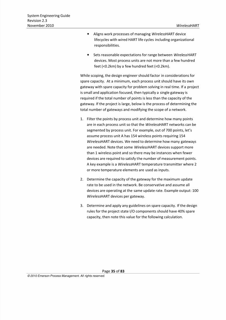
5. Scope the number of required gateways into subsections of the
process unit. If more than one gateway is needed per process unit,
then the design engineer should segment the networks such that
the gateways are distributed in the field like marshalling panels and
junction boxes. In Figure 9, the master drawing, the process unit
has 16 subsections labeled L-2 through L-17 that should be logically
segmented for coverage by gateways. Not every gateway needs to
have the same number of wireless points. If redundant gateways
are to be used, then double the number of gateways based on the
output from the above formula.
8/3/2019 Wireless Hart System Engineering Guide Rev 2.3
http://slidepdf.com/reader/full/wireless-hart-system-engineering-guide-rev-23 37/83
System Engineering Guide
Revision 2.3
November 2010 WirelessHART
Page 37 of 83 © 2010 Emerson Process Management. All rights reserved.
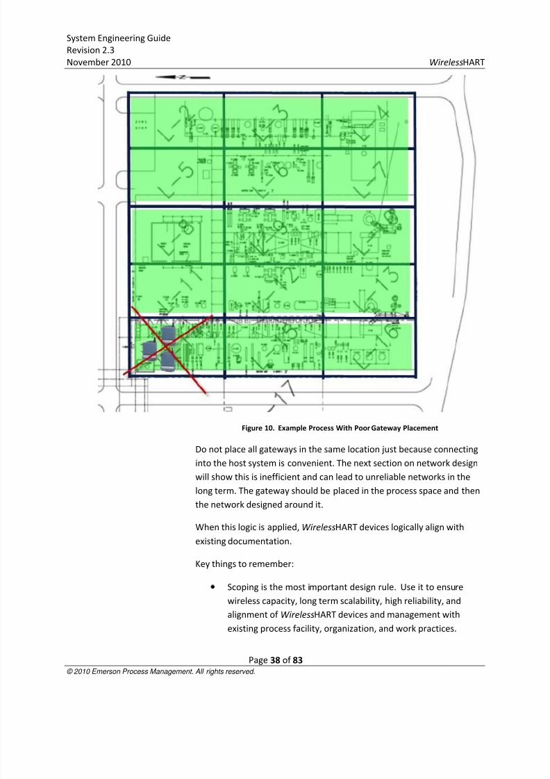
Figure 9. Example Process With Three WirelessHART Networks
This example shows three WirelessHART gateways supporting three
WirelessHART networks in the same process. This is analogous to having
three FOUNDATION Fieldbus segments in the same process unit. In this
example, the process unit subsections were grouped horizontally
instead of vertically to minimize the distance of the process unit. A key
consideration is that the gateways, regardless of manufacturer should
always be in the process space for which they supply I/O capacity.
Below is an image of what not to do:
8/3/2019 Wireless Hart System Engineering Guide Rev 2.3
http://slidepdf.com/reader/full/wireless-hart-system-engineering-guide-rev-23 38/83
8/3/2019 Wireless Hart System Engineering Guide Rev 2.3
http://slidepdf.com/reader/full/wireless-hart-system-engineering-guide-rev-23 39/83
System Engineering Guide
Revision 2.3
November 2010 WirelessHART
Page 39 of 83 © 2010 Emerson Process Management. All rights reserved.
Every WirelessHART gateway in a facility must have a unique
Network ID to properly segment the WirelessHART field
networks.
The output from the scoping phase should be a scaled drawingshowing the relative locations of assets and processes to be
automated and potential integration points for the
WirelessHART gateways.
DesigningThe following design rules are intended to be very conservative and are
based on real-world deployments of WirelessHART field networks. The
effective range of a device is the typical linear distance between
WirelessHART field devices when in the presence of process
infrastructure. Typically, if WirelessHART devices have no obstructionsbetween them, have clear line of sight (LOS), and are mounted at least 6
feet (2 meters) above the ground, then the effective range with 10
mW/10 dBi of power. Since the network is a self-organizing mesh, that
hops, or communication which gets repeated from 1 device to the next
device through another, to get to the gateway, thus would deliver an
effective range of 1500 feet (462m). Obstructions decrease the
effective range. Most process environments have high concentrations
of metal that reflect RF signals in a non-predictable manner bouncing
the signal off of the metal of the surrounding environment. The path of
an RF signal could easily be 750 feet (230m) even though theneighboring device separation is only 100 feet (31m) away. Below are
three basic classifications for effective range:
Heavy Obstruction – 100 ft. (30 m) with 10 mW/10 dBi of
power. This is the typical heavy density plant environment.
Cannot drive a truck or equipment through.
Medium Obstruction – 250 ft (76 m) with 10 mW/10 dBi of
power. This is the less light process areas, lots of space between
equipment and infrastructure.
Light Obstruction – 500 ft (152 m). Typical of tank farms.
Despite tanks being big obstructions themselves, lots of space
between and above makes for good RF propagation.
Obstructions between WirelessHART devices and devices
mounted a minimum distance above ground or obstructions.
8/3/2019 Wireless Hart System Engineering Guide Rev 2.3
http://slidepdf.com/reader/full/wireless-hart-system-engineering-guide-rev-23 40/83
System Engineering Guide
Revision 2.3
November 2010 WirelessHART
Page 40 of 83 © 2010 Emerson Process Management. All rights reserved.
These values are practical guidelines and are subject to change in
different types of process environments. Conditions that significantly
reduce effective range are:
Mounting field devices close to the ground, below ground, orunder water. The RF signal is absorbed and does not propagate.
Inside or outside of a building relative to the main network. RF
signals of any sort do not propagate well through concrete,
wood, etc. Typically, if there are wireless devices nearby on the
other side of the enclosure, no special design rules are needed.
If there is a high volume of WirelessHART devices isolated by
the network, consider scoping a network inside of the facility.
Small, fiberglass instrument and device enclosures often
deployed in very dirty or harsh environments show minimal
impact on propagation of RF signal and can be used. Large
Hoffman-style metal enclosures will prevent RF signals and are
not recommended without additional engineering
considerations.
The effective range is used to test the validity of network design.
There are 3 fundamental, recommended design rules.
1. Rule of 5 minimum – Every WirelessHART network should have a
minimum of 5 WirelessHART devices within effective range of the
gateway. Networks will work properly with less than 5
WirelessHART devices but will not benefit from the intrinsic
redundancy of a self-organizing mesh network and may require
repeaters. In a well formed, well designed network, new
WirelessHART devices can be added to the interior or perimeter of
the network without affecting operation or extensive consideration
for design.
Figure 11 is a simple design example. The network has been
properly scoped to a process unit and 4 WirelessHART devices have
been placed with a gateway on a scaled process drawing. The red
circle around the gateway represents the effective range of the
gateway. We see in this example, the Rule of 5 Minimum is broken
in that there are only 4 devices within effective range of the
gateway. This network will likely perform to specification, but it is
optimal to fortify for long term scalability and reliability by adding
more devices.
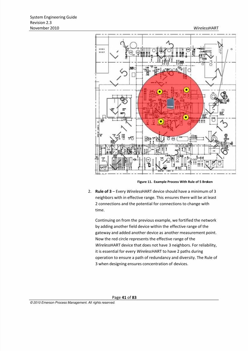
8/3/2019 Wireless Hart System Engineering Guide Rev 2.3
http://slidepdf.com/reader/full/wireless-hart-system-engineering-guide-rev-23 41/83
System Engineering Guide
Revision 2.3
November 2010 WirelessHART
Page 41 of 83 © 2010 Emerson Process Management. All rights reserved.
Figure 11. Example Process With Rule of 5 Broken
2. Rule of 3 – Every WirelessHART device should have a minimum of 3
neighbors with in effective range. This ensures there will be at least
2 connections and the potential for connections to change with
time.
Continuing on from the previous example, we fortified the network
by adding another field device within the effective range of the
gateway and added another device as another measurement point.
Now the red circle represents the effective range of the
WirelessHART device that does not have 3 neighbors. For reliability,it is essential for every WirelessHART to have 2 paths during
operation to ensure a path of redundancy and diversity. The Rule of
3 when designing ensures concentration of devices.
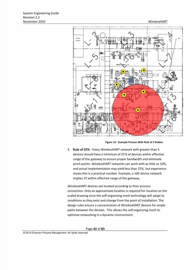
8/3/2019 Wireless Hart System Engineering Guide Rev 2.3
http://slidepdf.com/reader/full/wireless-hart-system-engineering-guide-rev-23 42/83
System Engineering Guide
Revision 2.3
November 2010 WirelessHART
Page 42 of 83 © 2010 Emerson Process Management. All rights reserved.
Figure 12. Example Process With Rule of 3 Broken
3. Rule of 25% - Every WirelessHART network with greater than 5
devices should have a minimum of 25% of devices within effective
range of the gateway to ensure proper bandwidth and eliminate
pinch points. WirelessHART networks can work with as little as 10%,
and actual implementation may yield less than 25%, but experience
shows this is a practical number. Example, a 100 device network
implies 25 within effective range of the gateway.
WirelessHART devices are located according to their process
connection. Only an approximate location is required for location on the
scaled drawing since the self-organizing mesh technology will adapt to
conditions as they exist and change from the point of installation. The
design rules ensure a concentration of WirelessHART devices for ample
paths between the devices. This allows the self-organizing mesh to
optimize networking in a dynamic environment.

8/3/2019 Wireless Hart System Engineering Guide Rev 2.3
http://slidepdf.com/reader/full/wireless-hart-system-engineering-guide-rev-23 43/83
System Engineering Guide
Revision 2.3
November 2010 WirelessHART
Page 43 of 83 © 2010 Emerson Process Management. All rights reserved.
When the Rule of 3 is broken, it too can be fortified by adding more
devices. As networks grow, Rule of 5 minimum and Rule of 3 become
irrelevant as there are many devices in the process space. Rule of 25%
becomes dominant for large networks to ensure there is ample
bandwidth for all devices in the network. Below is an example of whenRule of 25% is broken.
Figure 13. Example Process With Rule of 25% Broken
Rule of 25% can be resolved in several different ways. Below are three
options to fortify this network design, each with its own consideration:
1. Add more devices within the effective range of the gateway. While
this is a good solution, there may not be more points of value within
effective range of the gateway.
2. Move the gateway into a more central location relative to the
distribution of WirelessHART instrumentation. In this case, there
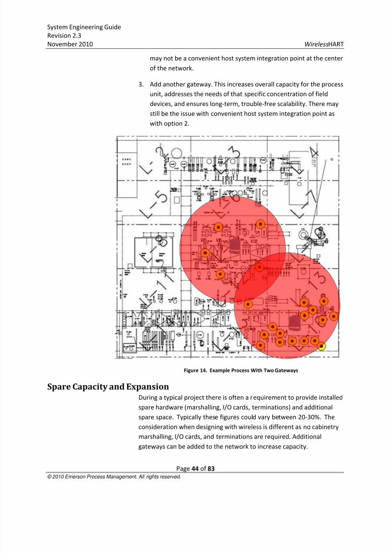
8/3/2019 Wireless Hart System Engineering Guide Rev 2.3
http://slidepdf.com/reader/full/wireless-hart-system-engineering-guide-rev-23 44/83
System Engineering Guide
Revision 2.3
November 2010 WirelessHART
Page 44 of 83 © 2010 Emerson Process Management. All rights reserved.
may not be a convenient host system integration point at the center
of the network.
3. Add another gateway. This increases overall capacity for the process
unit, addresses the needs of that specific concentration of fielddevices, and ensures long-term, trouble-free scalability. There may
still be the issue with convenient host system integration point as
with option 2.
Figure 14. Example Process With Two Gateways
Spare Capacity and ExpansionDuring a typical project there is often a requirement to provide installed
spare hardware (marshalling, I/O cards, terminations) and additional
spare space. Typically these figures could vary between 20-30%. The
consideration when designing with wireless is different as no cabinetry
marshalling, I/O cards, and terminations are required. Additional
gateways can be added to the network to increase capacity.

8/3/2019 Wireless Hart System Engineering Guide Rev 2.3
http://slidepdf.com/reader/full/wireless-hart-system-engineering-guide-rev-23 45/83
System Engineering Guide
Revision 2.3
November 2010 WirelessHART
Page 45 of 83 © 2010 Emerson Process Management. All rights reserved.
FortifyingStress testing the network design by altering the effective range of
devices is recommended to identify potential weaknesses in the
network. To stress test the network, reduce the effective range of the
devices in 10% increments. For example, suppose an effective range of
250 feet (76m) was used for initial design. Reducing effective range by
increments of 25 feet (8m) (10%) will reveal where the weak spots will
exist. At this point it is at the discretion of the network designer to what
level the network will be stressed; there is a limit of diminishing return.
The example below reveals that one WirelessHART device fails the Rule
of 3 under a 20% stress test of the effective range. Effective range is set
to 250 feet (76m) for the design test on the left and 200 feet (61m) for
the design test on the right.
Figure 15. Example Process: Standard Design (Left). Stress-Tested (Right)
The self-organizing mesh technology not only allows for more
WirelessHART field devices to be added to a network for the purposes
of automation, the means for simple design correction also exist.
Alternatives include moving the gateway location, adding a new
gateway to segment the network, adding more devices or adding
repeaters.
Repeaters are also an alternative to support the fortification of a
network. Instead of another WirelessHART device with a specific
measurement purpose, device repeater is used specifically for the

8/3/2019 Wireless Hart System Engineering Guide Rev 2.3
http://slidepdf.com/reader/full/wireless-hart-system-engineering-guide-rev-23 46/83
System Engineering Guide
Revision 2.3
November 2010 WirelessHART
Page 46 of 83 © 2010 Emerson Process Management. All rights reserved.
purposes of providing more connection within the network. Repeaters
can be used effectively within dense infrastructure if they are placed
above the infrastructure to maximize the effective range of devices
below. WirelessHART adapters may make cost-effective repeaters if
local power is available.
WirelessHART Availability and RedundancyThe WirelessHART field network is inherently redundant between the
wireless field devices and the gateway if the network design
recommendations are applied. The user should expect no less than 99%
reliability in the flow of data from each WirelessHART field device with
typical performance approaching 100%.
The following are considerations for maximizing system availability
between the host system and the WirelessHART Gateway:
1. Always properly ground gateways and field devices per
manufacturer recommendations.
2. Always employ proper lightning protection on gateways.
3. Always use an uninterruptible power supply (UPS) to power the
gateway. This is the primary source of gateway failure.
4. Deploy redundant gateways for the field network if measurements
are critical.
5. Make host systems connections to gateways redundant, especially if
redundant gateways are used. This includes physical connections,
switches and power supplies.
WirelessHART SecurityWhen designing networks, every gateway and thus every network must
have a unique Network ID. Device Join Keys may be configured as either
common per gateway or individual/unique per field device. If common
Device Join Keys are selected as the option, each field device will share
the same Device Join Key. If individual Device Join Keys are selected,each field device in the network will have a unique Device Join Key.
Individual Device Join Keys provide stronger security and are
recommended. Even with common Join Keys, it is recommended
practice to use different values for each gateway/network.
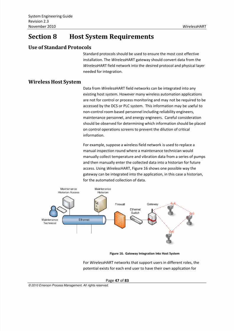
8/3/2019 Wireless Hart System Engineering Guide Rev 2.3
http://slidepdf.com/reader/full/wireless-hart-system-engineering-guide-rev-23 47/83
System Engineering Guide
Revision 2.3
November 2010 WirelessHART
Page 47 of 83 © 2010 Emerson Process Management. All rights reserved.
Section 8 Host System Requirements
Use of Standard ProtocolsStandard protocols should be used to ensure the most cost effective
installation. The WirelessHART gateway should convert data from the
WirelessHART field network into the desired protocol and physical layer
needed for integration.
Wireless Host SystemData from WirelessHART field networks can be integrated into any
existing host system. However many wireless automation applications
are not for control or process monitoring and may not be required to be
accessed by the DCS or PLC system. This information may be useful to
non-control room based personnel including reliability engineers,
maintenance personnel, and energy engineers. Careful consideration
should be observed for determining which information should be placed
on control operations screens to prevent the dilution of critical
information.
For example, suppose a wireless field network is used to replace a
manual inspection round where a maintenance technician would
manually collect temperature and vibration data from a series of pumps
and then manually enter the collected data into a historian for future
access. Using WirelessHART, Figure 16 shows one possible way the
gateway can be integrated into the application, in this case a historian,for the automated collection of data.
Figure 16. Gateway Integration Into Host System
For WirelessHART networks that support users in different roles, the
potential exists for each end user to have their own application for

8/3/2019 Wireless Hart System Engineering Guide Rev 2.3
http://slidepdf.com/reader/full/wireless-hart-system-engineering-guide-rev-23 48/83
System Engineering Guide
Revision 2.3
November 2010 WirelessHART
Page 48 of 83 © 2010 Emerson Process Management. All rights reserved.
collecting and analyzing data. For users who manually collect data,
WirelessHART provides the missing piece to their automation.
For long term scalability, where there may be 1000’s to 10,000’s of
WirelessHART instruments in a single plant. It will be important to havea coordinated effort to enable end users with different roles and
responsibilities to share the I/O capacity of gateways. There is no reason
why representatives from maintenance, utilities, operations,
health/safety/environmental, and asset management cannot share
network resources.
One architecture to consider is a centralized historian and centralized
asset management program shown in Figure 17. In this scenario,
multiple gateways are connected on the same Ethernet network and
server. Their data are sent to a centralized historian which can then be
connected to the applications for each of the end users. In this way,
host system resources can be shared, all WirelessHART instruments can
report to the same asset management solution, uniform security
policies can be enforced, and end users can see WirelessHART data in
applications specific to their roles.
Figure 17. Gateway Information Integrated Into Many Applications
Developing a host system strategy is essential to maximizing return on
investment for wireless that is adopted on a large scale. Successful
implementation means that data is going to the right people and being
turned into information for action. Often times, multiple users will see
the same data, but in the context of their applications. This also means
8/3/2019 Wireless Hart System Engineering Guide Rev 2.3
http://slidepdf.com/reader/full/wireless-hart-system-engineering-guide-rev-23 49/83
System Engineering Guide
Revision 2.3
November 2010 WirelessHART
Page 49 of 83 © 2010 Emerson Process Management. All rights reserved.
that every time a new WirelessHART device is introduced to the plant,
host system and integration issues do not need to be solved again and
again.
WirelessHART is truly scalable; WirelessHART devices can be added to anetwork without disrupting operation and more gateways can be added
to increase I/O capacity. This ability allows automation to be added,
solving problems without large project budgets once wireless network
infrastructure is in place. For example, a WirelessHART device can be
connected in minutes, configured in minutes, and integrated in minutes
if a host system strategy is in place.
Host IntegrationIntegration of data originating from the wireless gateway into a host
control system is normally performed in one of two ways - throughnative connectivity directly to the host system or using standard
protocols such as Modbus or OPC.
For native connectivity including vendor specific I/O cards, contact the
host vendor.
OPC and Modbus are non-proprietary protocols and use standard data
exchange and integration techniques to map data from the gateway
into the host control system. Typical data that is mapped to the host
are process variables (PV, SV, TV, QV) and overall device status.
Diagnostic information is typically passed to an asset managementsystem via Ethernet. Check with the gateway vendor for compatible
asset management packages.
Often, existing host systems can be a combination of legacy DCS and
PLC components and modern data management solutions such as
historians. WirelessHART gateways should support multiple
connections into multiple host systems over multiple protocols. This
enables WirelessHART networks to support modernization of an existing
host system. For example, suppose the existing DCS has no spare
capacity and can only receive the 4-20 mA signal from wired HARTdevices. A WirelessHART network could be serially connected to the DCS
to bypass the need for more Analog Input Cards to receive more process
variables, while in parallel, HART diagnostics flow to an asset
management program from existing wired HART devices with
WirelessHART adapters. This type of modernization project could enable
incremental modernization with an older host system and when the
scheduled turnaround occurs to upgrade the DCS, the existing

8/3/2019 Wireless Hart System Engineering Guide Rev 2.3
http://slidepdf.com/reader/full/wireless-hart-system-engineering-guide-rev-23 50/83
System Engineering Guide
Revision 2.3
November 2010 WirelessHART
Page 50 of 83 © 2010 Emerson Process Management. All rights reserved.
WirelessHART networks would transition to the new host system (see
Figure 18 for an example transitional architecture).
Figure 18. Using WirelessHART Gateway To Bridge Information From Non-HART Host
System
A key output from working with host system administrators is an
integration strategy to incorporate a plant-wide wireless infrastructure.
If doing a small application, a key output is the physical locations of
where to connect the gateways. These will be needed for the networkdesign process.
Key Outputs for Network Design:
Identifying a host system administrator and system integrator
who supports integration of WirelessHART data into the host
system.
Potential physical connection points for WirelessHART
gateways.
InteroperabilityConverting WirelessHART data from the gateway into standard
protocols including Modbus and OPC, ensures interoperability of all
WirelessHART networks with all host systems. Host systems based on
proprietary protocols may have difficulty.
8/3/2019 Wireless Hart System Engineering Guide Rev 2.3
http://slidepdf.com/reader/full/wireless-hart-system-engineering-guide-rev-23 51/83
System Engineering Guide
Revision 2.3
November 2010 WirelessHART
Page 51 of 83 © 2010 Emerson Process Management. All rights reserved.
Host System Support for WirelessHART FunctionalityA WirelessHART gateway typically performs all management of the
WirelessHART network and manages communications to and from the
WirelessHART field devices. The host system should not require any
special software to support the WirelessHART field network.
Configuration ToolsWirelessHART devices are based on HART. Therefore, existing HART
Field Communicators will work for configuration of the field devices.
Field Communicators will require the proper device descriptor for
configuration, which is no different for any other new HART device,
wired or wireless. Host system configuration will be dependent on the
host system. HART vendors with asset management software may
extend the benefits of remote management from wired to
WirelessHART devices via the gateway.
Control System GraphicsNot all data collected from the WirelessHART field network belongs on
the operator screen as part of control system graphics. The risk is that
non-pertinent information reaches the operator and becomes a
distraction from critical information.
The host system integration should be configured such that data from a
WirelessHART field network is delivered to the proper end-user even
though network resources are shared. To give some examples:
Data collected on consumption of power from rotating
equipment should go to the utilities manager.
Data collected on vibration spectrums of rotating equipment
should go to asset management.
Data collected on temperature alarms for rotating equipment
should go to operators in a non-obtrusive way and the reliability
manager.
Properly defining an integration strategy will ensure an efficient
collection of data from WirelessHART network and dissemination to
proper end-users. Many end users not typically receptive of the benefits
of automation have application specific databases into which data is
manually collected and uploaded. With the ability to integrate
WirelessHART data on many standard protocols, these existing end-user
specific databases can be automatically populated.
8/3/2019 Wireless Hart System Engineering Guide Rev 2.3
http://slidepdf.com/reader/full/wireless-hart-system-engineering-guide-rev-23 52/83
System Engineering Guide
Revision 2.3
November 2010 WirelessHART
Page 52 of 83 © 2010 Emerson Process Management. All rights reserved.
Node Addressing and Naming ConventionsA WirelessHART device should follow naming conventions of wired
HART devices.
Alarms and AlertsAlarms and alerts should be directed to the appropriate end-user and
their associated application and software. Alarm and alert
dissemination should be reflective of the end user and their
responsibility.
Maintenance StationWirelessHART devices provide internal diagnostics and process variables
like any wired HART device. Additional local diagnostics for network
connectivity should be accessible locally via a HART Field Communicator
with the correct Device Descriptor for the WirelessHART field device.
The WirelessHART gateway should also provide additional diagnostics
for network performance. The data from WirelessHART devices will not
propagate to the host system if the data is deemed questionable from
either a HART diagnostic or an extended delay in reception at the
gateway from the WirelessHART field device. Additionally, the gateway
is responsible for WirelessHART network management and network
diagnostics.
Diagnostics between the gateway and the host system will depend on
the host system and the gateway.
HistorianHistoric Data collection can be treated the same as any conventional
source (e.g. OSIsoft PI or any DCS historian package).

8/3/2019 Wireless Hart System Engineering Guide Rev 2.3
http://slidepdf.com/reader/full/wireless-hart-system-engineering-guide-rev-23 53/83
System Engineering Guide
Revision 2.3
November 2010 WirelessHART
Page 53 of 83 © 2010 Emerson Process Management. All rights reserved.
Section 9 Factory Acceptance Testing Requirements
IntroductionThe key deliverable of a factory acceptance test (FAT) is the integration
of data from WirelessHART instruments into the host system via the
gateway. The scope of the FAT should be agreed with the end user.
Typically only a subset of the field devices and gateways to be installed
is used during the FAT.
Factory StagingThe following are basic requirements for factory staging:
A sample of all applications, gateways and WirelessHART
devices is present.
Approved test plan, test procedure and test acceptance criteria.
HART Field Communicator and user interface to the
WirelessHART Gateway.
AssumptionsBelow are assumptions for the FAT:
Network topology testing is covered as part of the Site
Acceptance Test.
WirelessHART network design does not need to be tested at the
factory if network design recommendations are implemented.
The conservative nature and ability to fortify the network upon
installation with repeaters ensures high confidence of reliable
operation.
Factory Acceptance Test (FAT) RequirementsThe following are key requirements of a factory acceptance test:
Physical connection between the gateway and the host system
is verified. Can the gateway be accessed from the host system?
Protocol connection between the gateway and the application
that resides on the host system is verified. Can the data seen in
the gateway be seen in the application? Can the standard
parameters be properly mapped?

8/3/2019 Wireless Hart System Engineering Guide Rev 2.3
http://slidepdf.com/reader/full/wireless-hart-system-engineering-guide-rev-23 54/83
System Engineering Guide
Revision 2.3
November 2010 WirelessHART
Page 54 of 83 © 2010 Emerson Process Management. All rights reserved.
Gateway can support all necessary connections to all required
applications.
Device Descriptor (DD) for all field devices in any asset
management solution is tested. This ensures the correct DD isinstalled and valid. This is especially important for WirelessHART
devices that are new to the market.
FAT ProcedureSince there are no physical IO modules, software testing is performed
by simulation of I/O at the processor level. This level of simulation is
adequate to verify the application software within the host control
system.
As per IEC 62381 standards on factory acceptance testing, general
guidance as described for testing of bus interfaces and subsystems shall
apply. A subset of instruments (at least one of each type) shall be
connected to the gateway as a proof of concept demonstration of
integrated system functionality. This test should ideally verify the
connectivity of the field device to the gateway and from the gateway to
the host system.
Where physical devices will not be tested at the factory, emulation of
the interface will be performed if required
Below is a high level procedure for performing a FAT:
1. Power the gateway
2. Add one of each type of WirelessHART device to the network and
verify proper connectivity. All gateway fields for data from the
WirelessHART device should be properly populated.
3. Create first physical connection to the first required host system
application.
4. Verify connectivity between the gateway and the host system
application.
5. Integrate necessary data from each sample WirelessHART device
into the Host System Application.
a. Optional additional procedure is to change process variables
in the WirelessHART device through direct stimulation or
through simulation. All devices, once properly connected to

8/3/2019 Wireless Hart System Engineering Guide Rev 2.3
http://slidepdf.com/reader/full/wireless-hart-system-engineering-guide-rev-23 55/83
System Engineering Guide
Revision 2.3
November 2010 WirelessHART
Page 55 of 83 © 2010 Emerson Process Management. All rights reserved.
the gateway, should integrate identically over protocols like
Modbus and OPC.
6. Repeat steps 4-6 while adding host system connections to the
gateway until all expected connections the gateway are complete.
7. Test integration into an asset management solution if applicable.
a. Verify each WirelessHART device can be properly accessed
and configured via the asset management solution.
8. Add any additional procedures for verify control narratives and
monitoring narratives.
8/3/2019 Wireless Hart System Engineering Guide Rev 2.3
http://slidepdf.com/reader/full/wireless-hart-system-engineering-guide-rev-23 56/83
System Engineering Guide
Revision 2.3
November 2010 WirelessHART
Page 56 of 83 © 2010 Emerson Process Management. All rights reserved.
Section 10 Site Installation Guidelines
Installation follows very closely the installation practices of wired HART
instruments. Since there are no wires, WirelessHART devices can beinstalled as soon as the asset or infrastructure is in place and secure.
Network InstallationsAlways install the gateway first so that integration and field network
installation and commissioning can occur in parallel.
Field devices can be commissioned into the gateway and then
commissioned into the host system application.
In general, WirelessHART devices are installed per the practices of wired
HART devices. Always consult the product manual.
WirelessHART devices close to the gateway should always be installed
and commissioned first to ensure connections for potential devices that
cannot directly connect to the gateway. This is the easiest way to
establish the self-organizing mesh.
WirelessHART devices can be installed in close proximity to each other
without causing interference. The self-organizing mesh scheduling of
WirelessHART ensures devices in close proximity to each other are
silent, talking to each other, or talking on different RF channels whenother devices are communicating.
If a WirelessHART gateway antenna or WirelessHART device antenna is
to be mounted near a high power antenna of another wireless source,
then the antenna should be mounted at least 3 feet (approximately 1
meter) above or below to minimize potential interference.
Lightning ProtectionThe installation manuals of all WirelessHART devices should be
consulted prior to installation.
In general, WirelessHART devices should not be the tallest feature in the
plant to maximize protection against lightning.
Ensure adequate protection is provided between the WirelessHART
gateways and host system connection as a lightning strike could damage
more than just the WirelessHART gateway. Redundant gateways should

8/3/2019 Wireless Hart System Engineering Guide Rev 2.3
http://slidepdf.com/reader/full/wireless-hart-system-engineering-guide-rev-23 57/83
System Engineering Guide
Revision 2.3
November 2010 WirelessHART
Page 57 of 83 © 2010 Emerson Process Management. All rights reserved.
never be co-located to provide diversity of location in the event a single
WirelessHART gateway is struck by lightning.
In general, integrated wireless devices may provide better protection of
the system than wired, as the energy from a lightning strike will not beable to travel through the wiring and cause potential damage to other
components.
Standards such as NFPA 780 provide classification for zones of
protection from lightning as well as techniques for proper
implementation.
Wireless Connection Test ProcedureBefore beginning the wireless connection test procedure, verify the
WirelessHART device has basic connectivity to the network either
through the gateway interface, a local user interface on the device, or a
local connection via a HART Field Communicator. If the device is not
joining the network, verify the presence of power and the use of proper
Network ID and Join Key. This assumes the gateway is installed properly,
powered and accessible, that the network is designed per best
practices, and that there are devices to which the new device being
commissioned can connect.
1. Wait a minimum of at least 1 hour from initial powering of the
WirelessHART device before performing the wireless connection
test procedure. This dwell time ensures the device has had time tomake several connections for self-organization. Multiple devices can
be tested at the same time, and since they rely on each other, it is
optimal to have as many on the network as possible for initial
connection testing.
2. Verify that network diagnostics indicate the device has proper
bandwidth. The gateway should have an indication.
3. Verify each device has a minimum of two neighbors. The gateway
should have an indication.
4. Verify device reliability is 99% or greater. Statistics may need to be
reset and recertified to remove any anomalies incurred during start
up and not indicative of long term performance.
5. Verify sensor configuration per the loop sheet or other form
indicating designed configuration.

8/3/2019 Wireless Hart System Engineering Guide Rev 2.3
http://slidepdf.com/reader/full/wireless-hart-system-engineering-guide-rev-23 58/83
System Engineering Guide
Revision 2.3
November 2010 WirelessHART
Page 58 of 83 © 2010 Emerson Process Management. All rights reserved.
6. Perform any necessary zero trims for sensors.
7. Repeat for each device in the network.
If a device does not pass the wireless connection test, then follow these
basic steps:
1. Wait until entire network is built and operating for 24 hours before
considering further action. This will give the gateway time to
maximize its self-organization for best communication.
2. For the non-compliant device, verify proper path stability and RSSI
values. Path stabilities should be greater than 60% and RSSI should
be greater than -75 dBm.
3. Look at the location of the non-compliant device in the network.
Verify there is not a broken network design rule or an unexpected
installation resulting in poor RF signal propagation.
a. Add repeaters if necessary to fortify the network if the
device is isolated from the network with bad connections.
4. Verify the device has proper power and is working properly as a
sensor.
5. Verify the device update rate is not faster than the fastest allowed
by the gateway.
a. Either reduce the update rate of the field device or increase
the fastest allowed update rate on the gateway.
Network Checkout ProcedureBelow are basic steps for checking out a network:
1. Verify that all devices connected pass the wireless connectivity test.
The gateway should have an indication.
2. Verify a minimum of 15% of devices are directly connected to the
gateway. The design parameter is 25%; the minimum acceptable is
10%. The gateway should have an indication.
3. Verify overall network reliability is greater than 99%. The gateway
should have an indication.
8/3/2019 Wireless Hart System Engineering Guide Rev 2.3
http://slidepdf.com/reader/full/wireless-hart-system-engineering-guide-rev-23 59/83
System Engineering Guide
Revision 2.3
November 2010 WirelessHART
Page 59 of 83 © 2010 Emerson Process Management. All rights reserved.
Loop Checkout/Site Integration TestsOnce WirelessHART devices are connected to the gateway and the
network is checked out, the loop checkout may not be necessary in the
traditional sense.
Wireless connection testing verifies each field device has the proper
configuration. Since there are no wires to get confused and swapped,
there is no need to do the traditional loop check. Alternative loop
checks could be to ensure each field devices is reporting to the correct
gateway and each gateway is connected into the correct host system.
Traditional applications of sensor stimulus can be performed for
confidence, but are less valuable in a pure digital architecture if there is
complete assurance a field device was commissioned with the correct
tag and configuration.
Bench Simulation TestingEach WirelessHART field device is compliant with the IEC 62591 protocol
which has provisions for simulation. Each device can be put into a
simulation mode. Bench simulation testing should also verify that all
HART Field Communicators have the proper configuration and device
descriptors (DDs) for accessing the local user interface of field device
when in the field.
Provision of Spares
Below are the recommended spares to have onsite:
Spare lightning arrestor components for gateways, if lightning
protection is used.
Spare gateways should be kept according to spares policy for
host system equipment (e.g. I/O cards). Configurations for
gateways should be convenient for rapid replacement if
necessary.
Spare battery modules
Spare field devices as determined by the policy for wired field
devices. Consideration should be given for additional devices to
be used as repeaters if necessary.
8/3/2019 Wireless Hart System Engineering Guide Rev 2.3
http://slidepdf.com/reader/full/wireless-hart-system-engineering-guide-rev-23 60/83
System Engineering Guide
Revision 2.3
November 2010 WirelessHART
Page 60 of 83 © 2010 Emerson Process Management. All rights reserved.
Removal of Redundant Equipment Repeaters used temporarily to fortify a network can be removed and
reused if the WirelessHART network grows to a point where repeaters
are no longer needed.
Maintenance PracticesMaintain each WirelessHART device per the manual for the device.
The network will self organize and provide alerts for changes requiring
intervention. The gateway should have an indication of performance
issues in the network or field devices.

8/3/2019 Wireless Hart System Engineering Guide Rev 2.3
http://slidepdf.com/reader/full/wireless-hart-system-engineering-guide-rev-23 61/83
System Engineering Guide
Revision 2.3
November 2010 WirelessHART
Page 61 of 83 © 2010 Emerson Process Management. All rights reserved.
Section 11 Documenting in Intergraph SPI 2009WirelessHART devices can be fully documented in Intergraph SPI with
minimal customization. Below is an example of how to document
WirelessHART in a logical, linear order and assumes the reader is skilled
in working with Intergraph SPI. This is just an example to illustrate the
methodology. Ultimately it is the responsibility of project management
to create and reinforce the application of standards and guidelines
within the project environment.
User Defined FieldsThe first step is to create user defined fields that allow for the
accounting of WirelessHART engineering parameters that are necessary
for defining if a point is wireless and how that point will be connected to
a network.
The following global User Defined Fields should be created:
Figure 19. SPI User Defined Fields (UDF) For WirelessHART
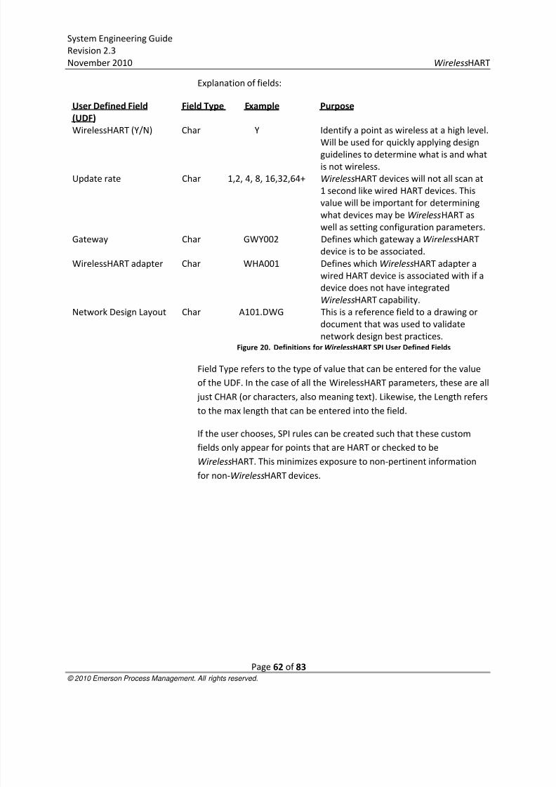
8/3/2019 Wireless Hart System Engineering Guide Rev 2.3
http://slidepdf.com/reader/full/wireless-hart-system-engineering-guide-rev-23 62/83
System Engineering Guide
Revision 2.3
November 2010 WirelessHART
Page 62 of 83 © 2010 Emerson Process Management. All rights reserved.
Explanation of fields:
User Defined Field
(UDF)
Field Type Example Purpose
WirelessHART (Y/N) Char Y Identify a point as wireless at a high level.
Will be used for quickly applying design
guidelines to determine what is and what
is not wireless.
Update rate Char 1,2, 4, 8, 16,32,64+ WirelessHART devices will not all scan at
1 second like wired HART devices. This
value will be important for determining
what devices may be WirelessHART as
well as setting configuration parameters.
Gateway Char GWY002 Defines which gateway a WirelessHART
device is to be associated.
WirelessHART adapter Char WHA001 Defines which WirelessHART adapter a
wired HART device is associated with if adevice does not have integrated
WirelessHART capability.
Network Design Layout Char A101.DWG This is a reference field to a drawing or
document that was used to validate
network design best practices.Figure 20. Definitions for WirelessHART SPI User Defined Fields
Field Type refers to the type of value that can be entered for the value
of the UDF. In the case of all the WirelessHART parameters, these are all
just CHAR (or characters, also meaning text). Likewise, the Length refers
to the max length that can be entered into the field.
If the user chooses, SPI rules can be created such that these custom
fields only appear for points that are HART or checked to be
WirelessHART. This minimizes exposure to non-pertinent information
for non-WirelessHART devices.

8/3/2019 Wireless Hart System Engineering Guide Rev 2.3
http://slidepdf.com/reader/full/wireless-hart-system-engineering-guide-rev-23 63/83
System Engineering Guide
Revision 2.3
November 2010 WirelessHART
Page 63 of 83 © 2010 Emerson Process Management. All rights reserved.
Filtered ViewsA custom view of the Instrument Index will be useful for applying design
guidelines for selecting what instruments are to be wireless as well as
seeing the organization of networks. Below is a sample view leveraging
the User Defined Fields shown in the previous section.
Figure 21. Custom View Of SPI’s WirelessHART User Defined Fields
The “Criticality” and “Update rate” should be foundations for any
engineering guidelines that determine whether a device is
WirelessHART. Some low criticality loops may have update rates fasterthan 4 seconds, and should be included with the design guidelines.
Because WirelessHART devices primarily run on batteries, WirelessHART
may not be suited for all fast update rate applications.
At a high level, using the “Criticality” and “Update Rate”, engineers can
determine whether a device should be WirelessHART. If wireless, the
device will need to be associated with a gateway. If a device can only be
specified as a wired HART device and requires a WirelessHART adapter,
then the “WirelessHART Adapter” tag information should be defined.
Every WirelessHART field network should be validated against network
design best practices. “Network Design Layout” provides a reference
field to link to the drawing on which network design best practices were
checked.

8/3/2019 Wireless Hart System Engineering Guide Rev 2.3
http://slidepdf.com/reader/full/wireless-hart-system-engineering-guide-rev-23 64/83
System Engineering Guide
Revision 2.3
November 2010 WirelessHART
Page 64 of 83 © 2010 Emerson Process Management. All rights reserved.
Creating Instrument TypesEarly in the process, symbols and instrument types should be defined
and a WirelessHART instrument library should be developed. Below the
basic modifications to a HART device to create a WirelessHART
instrument type is illustrated.
Figure 22. Defining WirelessHART Instrument Type In SPI
The first step is to create a new device with a new description. In this
example, we have created a WirelessHART flow transmitter. Please note
that if the device will be specified as a wired HART device with a
WirelessHART adapter, no new instrument types are necessary.

8/3/2019 Wireless Hart System Engineering Guide Rev 2.3
http://slidepdf.com/reader/full/wireless-hart-system-engineering-guide-rev-23 65/83
System Engineering Guide
Revision 2.3
November 2010 WirelessHART
Page 65 of 83 © 2010 Emerson Process Management. All rights reserved.
Figure 23. Defining A New WirelessHART Instrument In SPI
Nothing needs to change on the general tab. Be sure to leverage that
the device is a HART AI or a HART AO so that all of the basic parameters
of HART apply. Manage the wiring, or lack of wiring separately. The fact
that WirelessHART is based on HART allows leverage these pre-defined
variables.
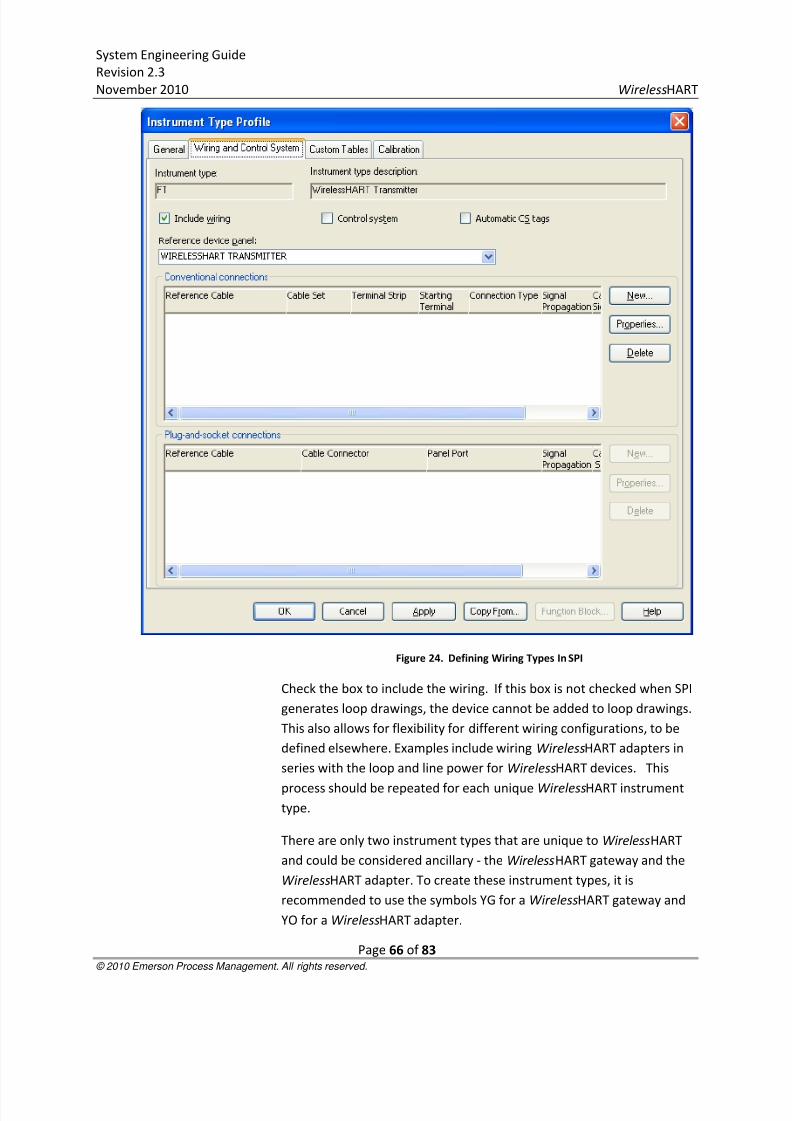
8/3/2019 Wireless Hart System Engineering Guide Rev 2.3
http://slidepdf.com/reader/full/wireless-hart-system-engineering-guide-rev-23 66/83
System Engineering Guide
Revision 2.3
November 2010 WirelessHART
Page 66 of 83 © 2010 Emerson Process Management. All rights reserved.
Figure 24. Defining Wiring Types In SPI
Check the box to include the wiring. If this box is not checked when SPI
generates loop drawings, the device cannot be added to loop drawings.
This also allows for flexibility for different wiring configurations, to be
defined elsewhere. Examples include wiring WirelessHART adapters in
series with the loop and line power for WirelessHART devices. This
process should be repeated for each unique WirelessHART instrument
type.
There are only two instrument types that are unique to WirelessHART
and could be considered ancillary - the WirelessHART gateway and the
WirelessHART adapter. To create these instrument types, it is
recommended to use the symbols YG for a WirelessHART gateway and
YO for a WirelessHART adapter.
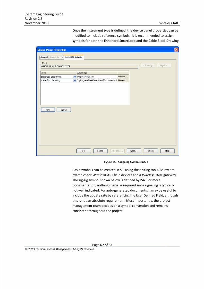
8/3/2019 Wireless Hart System Engineering Guide Rev 2.3
http://slidepdf.com/reader/full/wireless-hart-system-engineering-guide-rev-23 67/83
System Engineering Guide
Revision 2.3
November 2010 WirelessHART
Page 67 of 83 © 2010 Emerson Process Management. All rights reserved.
Once the instrument type is defined, the device panel properties can be
modified to include reference symbols. It is recommended to assign
symbols for both the Enhanced SmartLoop and the Cable Block Drawing.
Figure 25. Assigning Symbols In SPI
Basic symbols can be created in SPI using the editing tools. Below are
examples for WirelessHART field devices and a WirelessHART gateway.
The zig-zig symbol shown below is defined by ISA. For more
documentation, nothing special is required since signaling is typically
not well indicated. For auto-generated documents, it may be useful to
include the update rate by referencing the User Defined Field, although
this is not an absolute requirement. Most importantly, the project
management team decides on a symbol convention and remains
consistent throughout the project.
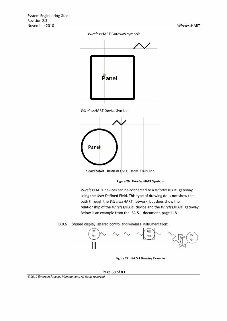
8/3/2019 Wireless Hart System Engineering Guide Rev 2.3
http://slidepdf.com/reader/full/wireless-hart-system-engineering-guide-rev-23 68/83
System Engineering Guide
Revision 2.3
November 2010 WirelessHART
Page 68 of 83 © 2010 Emerson Process Management. All rights reserved.
WirelessHART Gateway symbol:
WirelessHART Device Symbol:
Figure 26. WirelessHART Symbols
WirelessHART devices can be connected to a WirelessHART gateway
using the User Defined Field. This type of drawing does not show the
path through the WirelessHART network, but does show the
relationship of the WirelessHART device and the WirelessHART gateway:
Below is an example from the ISA-5.1 document, page 118.
Figure 27. ISA 5.1 Drawing Example

8/3/2019 Wireless Hart System Engineering Guide Rev 2.3
http://slidepdf.com/reader/full/wireless-hart-system-engineering-guide-rev-23 69/83
System Engineering Guide
Revision 2.3
November 2010 WirelessHART
Page 69 of 83 © 2010 Emerson Process Management. All rights reserved.
Please note that inclusion of update rates and the wireless signal
symbol are optional. The authors of this document found the practice of
including such information supportive of adopting and managing the
unique attributes of WirelessHART.
Loop DrawingsGiven that WirelessHART field devices do not require signal cabling, the
documentation of the equivalent of wireless loop drawing is very simple
to create.
The key information is to relate each wireless field device to the
respective gateway. It is recommended that a basic wireless loop
drawing show the traditional tag information as well as the
WirelessHART User Defined Fields. This way, it is very clear to see which
wireless devices are associated to which WirelessHART gateway.Currently, Intergraph SPI 2009 does not have the means to implement
this in a specific drawing, thus it is recommended to use the
Instrumentation Index showing the WirelessHART User Defined Fields.
In the image below, a comprehensive list of WirelessHART devices are
shown associated to different gateways.
Figure 28. Filtered View Of WirelessHART Tags
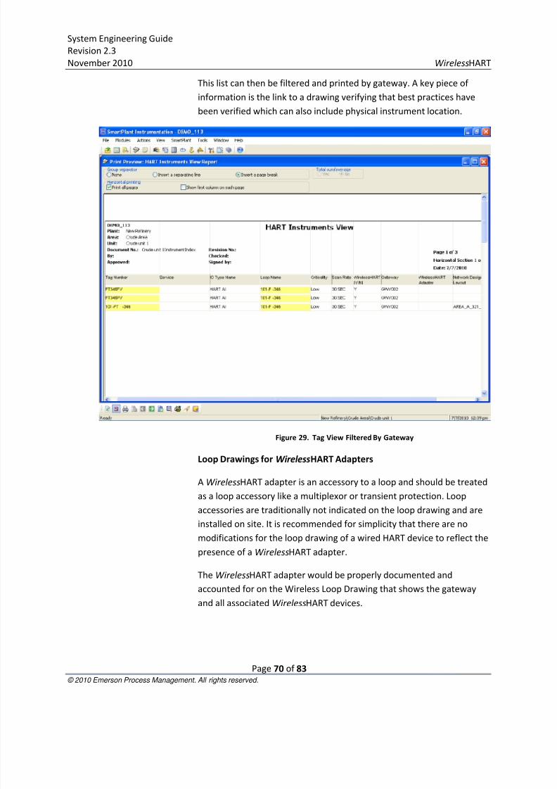
8/3/2019 Wireless Hart System Engineering Guide Rev 2.3
http://slidepdf.com/reader/full/wireless-hart-system-engineering-guide-rev-23 70/83
System Engineering Guide
Revision 2.3
November 2010 WirelessHART
Page 70 of 83 © 2010 Emerson Process Management. All rights reserved.
This list can then be filtered and printed by gateway. A key piece of
information is the link to a drawing verifying that best practices have
been verified which can also include physical instrument location.
Figure 29. Tag View Filtered By Gateway
Loop Drawings for WirelessHART Adapters
A WirelessHART adapter is an accessory to a loop and should be treated
as a loop accessory like a multiplexor or transient protection. Loop
accessories are traditionally not indicated on the loop drawing and are
installed on site. It is recommended for simplicity that there are no
modifications for the loop drawing of a wired HART device to reflect the
presence of a WirelessHART adapter.
The WirelessHART adapter would be properly documented and
accounted for on the Wireless Loop Drawing that shows the gateway
and all associated WirelessHART devices.

8/3/2019 Wireless Hart System Engineering Guide Rev 2.3
http://slidepdf.com/reader/full/wireless-hart-system-engineering-guide-rev-23 71/83
System Engineering Guide
Revision 2.3
November 2010 WirelessHART
Page 71 of 83 © 2010 Emerson Process Management. All rights reserved.
Gateway Cable Block Drawings
A useful drawing to create is a Gateway Cable Block Drawing showing
the gateway power and communication connections. All WirelessHART
gateways, regardless of vendor, should have uninterruptable powersupplies to maximize system reliability.
Figure 30. Gateway Cable Block Diagram
An additional drawing to consider, possible with a Cable Block Diagram,
would be to show all gateways assigned to an area on the same
document for convenience.
SPI Specification SheetsExisting specification sheets can be used to indicate WirelessHART
devices. Key fields to change are listed in the table below:
Specification Field Typical Value
Update rate 4, 8, 16, 32, 64+
Power Supply Intrinsically safe, field replaceable battery
Communication Type WirelessHART
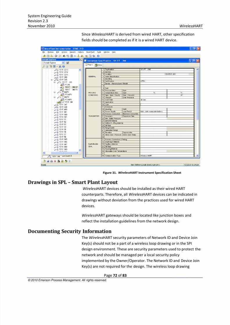
8/3/2019 Wireless Hart System Engineering Guide Rev 2.3
http://slidepdf.com/reader/full/wireless-hart-system-engineering-guide-rev-23 72/83
System Engineering Guide
Revision 2.3
November 2010 WirelessHART
Page 72 of 83 © 2010 Emerson Process Management. All rights reserved.
Since WirelessHART is derived from wired HART, other specification
fields should be completed as if it is a wired HART device.
Figure 31. WirelessHART Instrument Specification Sheet
Drawings in SPL – Smart Plant Layout WirelessHART devices should be installed as their wired HART
counterparts. Therefore, all WirelessHART devices can be indicated in
drawings without deviation from the practices used for wired HART
devices.
WirelessHART gateways should be located like junction boxes and
reflect the installation guidelines from the network design.
Documenting Security InformationThe WirelessHART security parameters of Network ID and Device Join
Key(s) should not be a part of a wireless loop drawing or in the SPI
design environment. These are security parameters used to protect the
network and should be managed per a local security policy
implemented by the Owner/Operator. The Network ID and Device Join
Key(s) are not required for the design. The wireless loop drawing

8/3/2019 Wireless Hart System Engineering Guide Rev 2.3
http://slidepdf.com/reader/full/wireless-hart-system-engineering-guide-rev-23 73/83
System Engineering Guide
Revision 2.3
November 2010 WirelessHART
Page 73 of 83 © 2010 Emerson Process Management. All rights reserved.
associates the WirelessHART device with the WirelessHART gateway
tags. Separately, secure documents containing WirelessHART security
provisioning including the WirelessHART gateway tag can be used to
cross reference the Network ID and Join Key(s). Remember, all Network
IDs and common Device Join Keys (if used) should be unique for everygateway and every WirelessHART field network. This type of security
management is similar to the management of security information for
control systems and servers
.
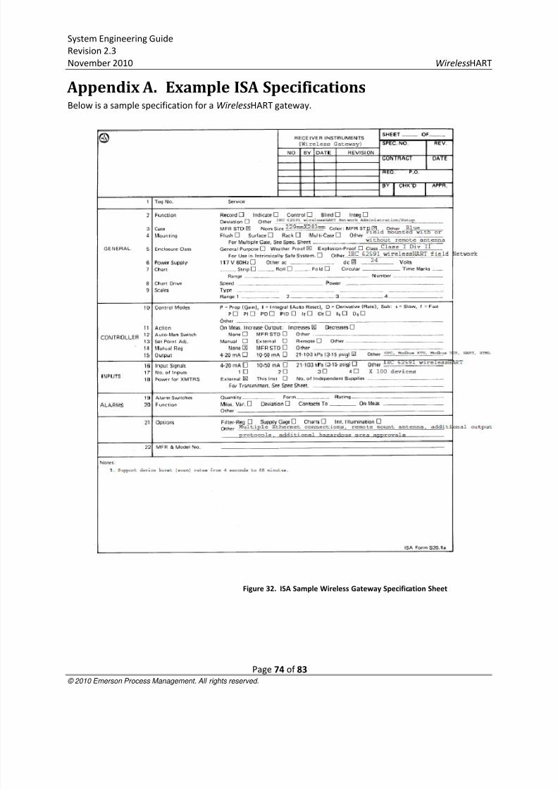
8/3/2019 Wireless Hart System Engineering Guide Rev 2.3
http://slidepdf.com/reader/full/wireless-hart-system-engineering-guide-rev-23 74/83
System Engineering Guide
Revision 2.3
November 2010 WirelessHART
Page 74 of 83 © 2010 Emerson Process Management. All rights reserved.
Appendix A. Example ISA SpecificationsBelow is a sample specification for a WirelessHART gateway.
Figure 32. ISA Sample Wireless Gateway Specification Sheet
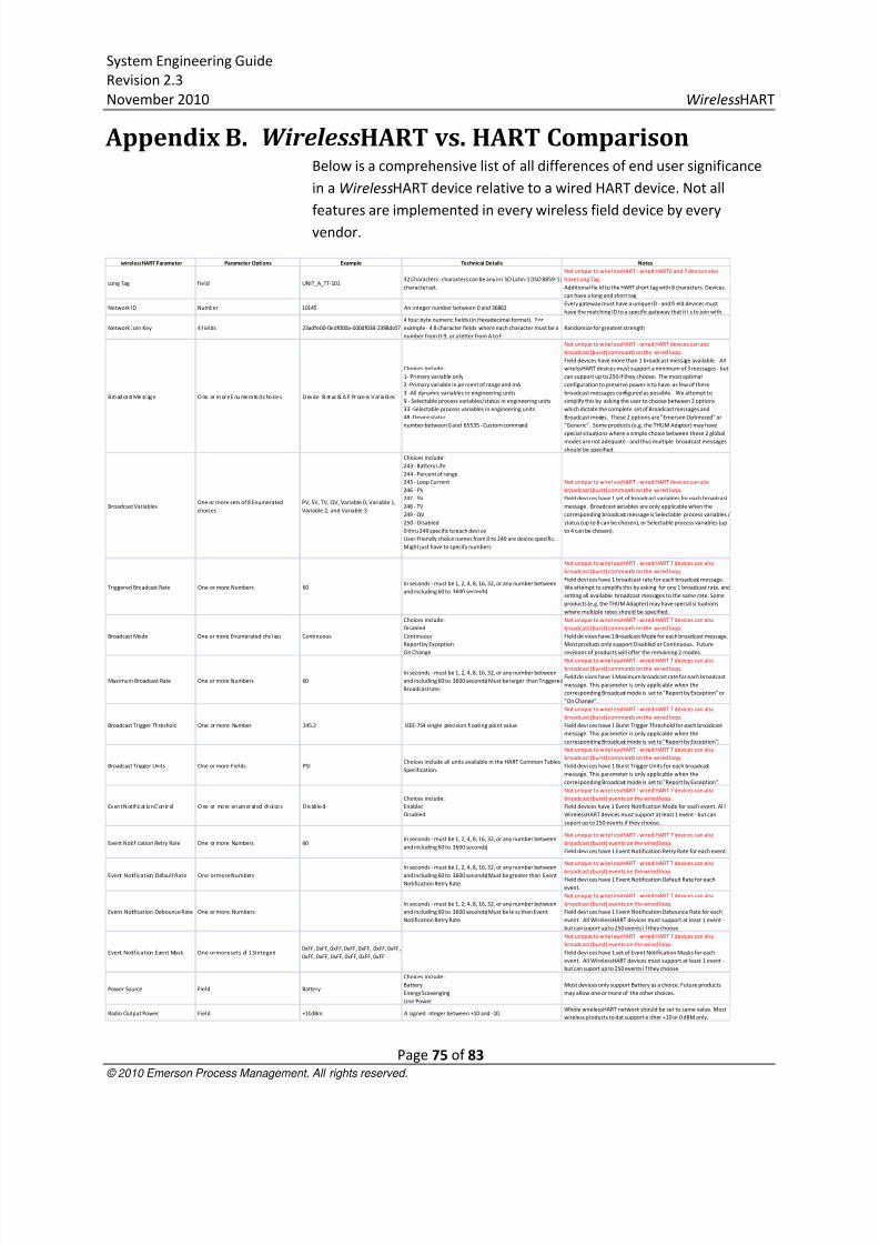
8/3/2019 Wireless Hart System Engineering Guide Rev 2.3
http://slidepdf.com/reader/full/wireless-hart-system-engineering-guide-rev-23 75/83
System Engineering Guide
Revision 2.3
November 2010 WirelessHART
Page 75 of 83 © 2010 Emerson Process Management. All rights reserved.
Appendix B. WirelessHART vs. HART ComparisonBelow is a comprehensive list of all differences of end user significance
in a WirelessHART device relative to a wired HART device. Not all
features are implemented in every wireless field device by every
vendor.
wirelessHART Parameter Parameter Options Example Technical Details Notes
Long Tag field UNIT_A_TT-10132 Characters - characters can be any in I SO Latin-1 (ISO 8859-1)
character set.
Not unique to wirel essHART - wired HART6 and 7 devices also
have Long Tag.
Additional fie ld to the HART short tag with 8 characters. Devices
can have a long and short tag.
Network ID Number 10145 An integer number between 0 and 36863Every gateway must have a unique ID - and fi eld devices must
have the matching ID to a specific gateway that it i s to join with.
Network Join Key 4 fields 23adfe00-0edf000a-000df038-2398dc07
4 four byte numeric fields (in Hexadecimal format). For
example - 4 8 character fields where each character must be a
number from 0-9, or a letter from A to F.
Randomize for greatest strength
B ro ad cast Me ss ag e One or m or e E nu me rate d c ho ice s D ev ice St at us & A ll Pr oce ss Var iables
Choices include:
1- Primary variable only
2 -Primary variable in pe rcent of range and mA
3 -All dynamic variables in engineering units
9 - Selectable process variables/status in engineering units
33 -Selectable process variables in engineering units
48 -Device status
number between 0 and 65535 - Custom command
Not unique to wirel essHART - wired HART devices can also
broadcast (burst) commands on the wired loop.
Field devices have more than 1 broadcast message available. All
wirelssHART devices must support a minimum of 3 messages - but
can support up to 250 if they choose. The most optimal
configuration to preserve power is to have as few of these
broadcast messages configured as possible. We attempt to
simplify this by asking the user to choose between 2 options
which dictate the complete set of Broadcast messages and
Broadcast modes. These 2 options are "Emerson Optimized" or
"Generic". Some products (e.g. the THUM Adapter) may have
special situations where a simple choice between these 2 globalmodes are not adequate - and thus multiple broadcast messages
should be specified.
Broadcast VariablesOne or more sets of 8 Enumerated
choices
PV, SV, TV, QV, Variable 0, Variable 1,
Variable 2, and Variable 3
Choices include:
243 - Battery Life
244 - Percent of range
245 - Loop Current
246 - PV
247 - SV
248 - TV
249 - QV
250 - Disabled
0 thru 249 specific to each devi ce
User-friendly choice names from 0 to 249 are device specific.
Might just have to specify numbers
Not unique to wirel essHART - wired HART devices can also
broadcast (burst) commands on the wired loop.
Field devi ces have 1 set of broadcast variables for each broadcast
message. Broadcast variables are only applicable when the
corresponding broadcast message is Selectable process variables /
status (up to 8 can be chosen), or Selectable process variables (up
to 4 can be chosen).
Triggered Broadcast Rate One or more Numbers 60In seconds - must be 1, 2, 4, 8, 16, 32, or any number between
and including 60 to 3600 seconds)
Not unique to wirel essHART - wired HART 7 devices can also
broadcast (burst) commands on the wired loop.
Field devi ces have 1 broadcast rate for each broadcast message.
We attempt to simplify this by asking for ony 1 broadcast rate, and
setting all available broadcast messages to the same rate. Some
products (e.g. the THUM Adapter) may have special si tuations
where multiple rates should be specified.
Broadcast Mode One or more Enumerated choi ces Continuous
Choices include:
Disabled
Continuous
Report by Exception
On Change
Not unique to wirel essHART - wired HART 7 devices can also
broadcast (burst) commands on the wired loop.
Field de vices have 1 Broadcast Mode for each broadcast message.
Most products only support Disabled or Continuous. Future
revisions of products will offer the remaining 2 modes.
Maximum Broadcast Rate One or more Numbers 60
In seconds - must be 1, 2, 4, 8, 16, 32, or any number between
and including 60 to 3600 seconds) Must be larger than Triggered
Broadcast rate.
Not unique to wirel essHART - wired HART 7 devices can also
broadcast (burst) commands on the wired loop.
Field de vices have 1 Maximum broadcast rate for each broadcast
message. This parameter is only applicable when the
corresponding Broadcast mode is set to "Report by Exception" or
"On Change".
Broadcast Trigger Threshold One or more Number 345.2 IEEE-754 single precision floating point value
Not unique to wirel essHART - wired HART 7 devices can also
broadcast (burst) commands on the wired loop.
Field devi ces have 1 Burst Trigger Threshold for each broadcast
message. This parameter is only applicable when the
corresponding Broadcast mode is set to "Report by Exception".
Broadcast Trigger Units One or more Fields PSIChoices include all units available in the HART Common Tables
Specification.
Not unique to wirel essHART - wired HART 7 devices can also
broadcast (burst) commands on the wired loop.
Field devi ces have 1 Burst Trigger Units for each broadcast
message. This parameter is only applicable when the
corresponding Broadcast mode is set to "Report by Exception".
Ev en t N ot if ic at io n C on tr ol One or mo re en um er at ed ch oice s D is ab le d
Choices include:
Enabled
Disabled
Not unique to wirel essHART - wired HART 7 devices can also
broadcast (burst) events on the wired loop.
Field devices have 1 Event Notification Mode for each event. Al l
WirelessHART devices must support at least 1 event - but can
suport up to 250 events if they choose.
Event Notification Retry Rate One or more Numbers 60In seconds - must be 1, 2, 4, 8, 16, 32, or any number between
and including 60 to 3600 seconds)
Not unique to wirel essHART - wired HART 7 devices can also
broadcast (burst) events on the wired loop.
Field devi ces have 1 Event Notification Retry Rate for each event.
Event Notification Default Rate One or more Numbers
In seconds - must be 1, 2, 4, 8, 16, 32, or any number between
and including 60 to 3600 seconds) Must be greater than Event
Notification Retry Rate
Not unique to wirel essHART - wired HART 7 devices can also
broadcast (burst) events on the wired loop.Field devi ces have 1 Event Notification Default Rate for each
event.
Event Notification Debounce Rate One or more Numbers
In seconds - must be 1, 2, 4, 8, 16, 32, or any number between
and including 60 to 3600 seconds) Must be le ss than Event
Notification Retry Rate
Not unique to wirel essHART - wired HART 7 devices can also
broadcast (burst) events on the wired loop.
Field devi ces have 1 Event Notification Debounce Rate for each
event. All WirelessHART devices must support at least 1 event -
but can suport up to 250 events i f they choose.
Event Notification Event Mask One or more sets of 13 integers0xFF, 0xFF, 0xFF, 0xFF, 0xFF, 0xFF, 0xFF,
0xFF, 0xFF, 0xFF, 0xFF, 0xFF, 0xFF
Not unique to wirel essHART - wired HART 7 devices can also
broadcast (burst) events on the wired loop.
Field devi ces have 1 set of Event Notification Masks for each
event. All WirelessHART devices must support at least 1 event -
but can suport up to 250 events i f they choose.
Power Source Field Battery
Choices include:
Battery
Energy Scavenging
Line Power
Most devices only support Battery as a choice. Future products
may allow one or more of the other choices.
Radio Output Power Field +10dBm A signed integer between +10 and -10.Whole wirelessHART network should be set to same value. Most
wireless products to dat support e ither +10 or 0 dBM only.

8/3/2019 Wireless Hart System Engineering Guide Rev 2.3
http://slidepdf.com/reader/full/wireless-hart-system-engineering-guide-rev-23 76/83
System Engineering Guide
Revision 2.3
November 2010 WirelessHART
Page 76 of 83 © 2010 Emerson Process Management. All rights reserved.
Appendix C. AMS Wireless Snap-On ApplicationAll design parameters discussed in the previous section are automated
in the AMS Wireless Snap-On Application from the Asset Optimization
Division of Emerson Process Management. Networks can be design and
files saved to support the engineering process. The design features of
the application require no additional software.
AMS Snap-On documentation is available on-line:
http://www2.emersonprocess.com/siteadmincenter/PM%20Asset%20Optimization%20Documents/Pro
ductDataSheets/amsdm_ds_wirelesssnapon.pdf
8/3/2019 Wireless Hart System Engineering Guide Rev 2.3
http://slidepdf.com/reader/full/wireless-hart-system-engineering-guide-rev-23 77/83
System Engineering Guide
Revision 2.3
November 2010 WirelessHART
Page 77 of 83 © 2010 Emerson Process Management. All rights reserved.
Appendix D. Wireless Spectrum Governance
Wireless applications have been deployed in the process industry for
over 40 years. In any process facility, many applications using RF signals
including personnel communications, RF ID systems, ad hoc systems,
cell phones may exist. The essential ingredients to making wireless
automation feasible were solving the problems of power to enable
devices to operate on batteries for multiple years; self-mitigating all
obstacles in the process environment so advanced wireless knowledge
was not a requirement for adoption; and coexisting with other sources
of wireless energy.
WirelessHART operates in the 2.4 GHz Industrial, Scientific, and Medical
(ISM) radio band that typically operates from 2.400-2.500 GHz. The
exact frequency limitations and RF output power levels may be slightly
different country by country. WirelessHART employs limitations that
allow for universal operation in almost all countries with exceptions
being noted for specific products by device manufactures. The ISM radio
bands are license-free, but do require approval from governmental
regulating agencies. These approvals are typically obtained by the
WirelessHART vendor. Since vendors for multiple applications can use
the same spectrum, WirelessHART must be able to successfully coexist.
WirelessHART uses multiple techniques to coexist with other wireless
applications:
Network segmentation – allows thousands of WirelessHART
devices to exist in the same physical space, provided each
network has a unique Network ID.
Spectrum isolation – wireless applications in different portions
of the spectrum do not “see” each other and thus do not
interfere with each other.
Low power – WirelessHART devices are very low power relative
to handheld personnel communicators, Wi-Fi, and RFID readers.
This prevents WirelessHART interference with these high power
applications.
8/3/2019 Wireless Hart System Engineering Guide Rev 2.3
http://slidepdf.com/reader/full/wireless-hart-system-engineering-guide-rev-23 78/83
System Engineering Guide
Revision 2.3
November 2010 WirelessHART
Page 78 of 83 © 2010 Emerson Process Management. All rights reserved.
Spatial hopping – self-organizing mesh networks can hop on
different paths that may be exposed to different RF conditions.
The WirelessHART devices self-organize paths through theprocess environment that mitigate RF obstacles the same way
as physical obstacles.
Channel hopping – WirelessHART devices use 15 channels
within the 2.4 GHz spectrum. Pseudo-random of channel usage
ensures that interference on one or several channels does not
prevent reliable communications.
DSSS coding – allows transmissions to be modulated with
unique encoding for the purposes of jamming resistance,
channel sharing, and improved signal/noise level. DSSS Coding
extends radio receiver sensitivity through digital processing.
Time Synchronized Mesh Protocol (TSMP) – provides the
synchronized time slots which schedule coordinated network
communication, only when required.
Despite these coexistence features, it is still beneficial to have some
form of wireless governance. WirelessHART can be interfered with, but
only under conditions that likely will disrupt all wireless applications
operating in the 2.4 GHz spectrum.
A key example is broadband interference. Many legacy wireless systems
are very high power. As an example, consider a personnel
communication system using high power two-way radios operating in
the 800 MHz frequency range. Although the system is legal and
operating according to specifications, it can emit broadband
interference that spans several GHz in the spectrum. This broadband
interference then affects all applications in other spectrums by reducing
the signal-to-noise ratio. The simple solution is to place a band pass
filter on all systems such that they only emit RF energy in the spectrum
licensed for usage. See the illustrative diagram below showing
broadband interference before and after the implementation of a low
pass filter.
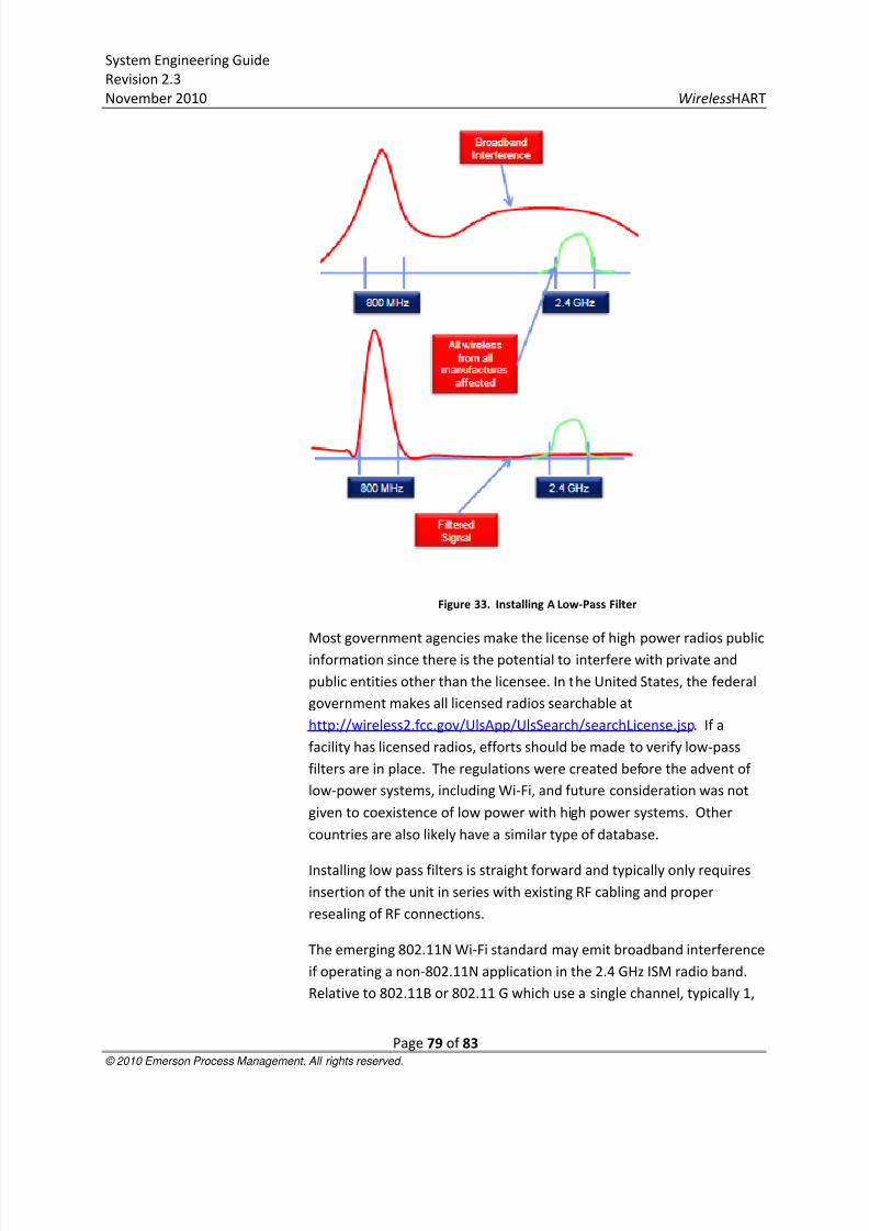
8/3/2019 Wireless Hart System Engineering Guide Rev 2.3
http://slidepdf.com/reader/full/wireless-hart-system-engineering-guide-rev-23 79/83
System Engineering Guide
Revision 2.3
November 2010 WirelessHART
Page 79 of 83 © 2010 Emerson Process Management. All rights reserved.
Figure 33. Installing A Low-Pass Filter
Most government agencies make the license of high power radios public
information since there is the potential to interfere with private and
public entities other than the licensee. In the United States, the federal
government makes all licensed radios searchable at
http://wireless2.fcc.gov/UlsApp/UlsSearch/searchLicense.jsp. If a
facility has licensed radios, efforts should be made to verify low-pass
filters are in place. The regulations were created before the advent of
low-power systems, including Wi-Fi, and future consideration was not
given to coexistence of low power with high power systems. Other
countries are also likely have a similar type of database.
Installing low pass filters is straight forward and typically only requires
insertion of the unit in series with existing RF cabling and proper
resealing of RF connections.
The emerging 802.11N Wi-Fi standard may emit broadband interference
if operating a non-802.11N application in the 2.4 GHz ISM radio band.
Relative to 802.11B or 802.11 G which use a single channel, typically 1,

8/3/2019 Wireless Hart System Engineering Guide Rev 2.3
http://slidepdf.com/reader/full/wireless-hart-system-engineering-guide-rev-23 80/83
System Engineering Guide
Revision 2.3
November 2010 WirelessHART
Page 80 of 83 © 2010 Emerson Process Management. All rights reserved.
6, or 11, 802.11N will use multiple adjacent channels to enable
increased bandwidth for demanding applications such as bulk data
transfer, security cameras, and streaming video. 802.11N can be
operated in either the 2.4GHz ISM band or the 5.8 GHz ISM band.
Operation in the 5.8 GHz band applies the principle of spectrumisolation and comes with the additional advantage that 5.8 GHz RF
signals can transfer information much faster than 2.4 GHz RF signals due
to the much faster modulation.
Another emerging standard is Wi-Max, which operates in the 2.3 GHz,
2.5 GHz, or 3.5 GHz radio bands. Although these spectrums do not
overlap the 2.4 GHz spectrum, there are no provisions in the Wi-Max
standard to adopt or enforce the usage of low-pass filters in either
clients or Access Points. The high power of Wi-Max has the potential to
interfere with all wireless applications specifically designed foroperation in the 2.4 GHz spectrum. Wi-Max clients should have limited
deployment in the process facility and Wi-Max systems should be
deployed in the 3.5 GHz spectrum to minimize risk of broadband
interference.
Aside from managing potential broadband interference sources,
wireless governance a basic process. Below is a summary of key
considerations for wireless governance:
A local wireless governance policy should serve the purpose
of documenting all wireless sources in a plant and enforcing
best practices for wireless coexistence.
Enforce proper installation and compliance with regulation
for all wireless applications with regards to power levels,
spectrum usage, and encryption in accordance with
government regulation.
Provide guidelines for wireless applications spectrum usage.
o Limit 802.11N Applications to 5.8 GHz ISM radio
band.
o Limit Wi-Max deployment to the 3.5 GHz spectrum.
o Put high bandwidth wireless applications such as
security cameras in the 5.8 GHz radio band.
Support proper segmentation of WirelessHART networks.

8/3/2019 Wireless Hart System Engineering Guide Rev 2.3
http://slidepdf.com/reader/full/wireless-hart-system-engineering-guide-rev-23 81/83
System Engineering Guide
Revision 2.3
November 2010 WirelessHART
Page 81 of 83 © 2010 Emerson Process Management. All rights reserved.
o Every network in the process facility should have a
unique Network ID Key to prevent WirelessHART
devices from wasting energy trying to join the
wrong subnet.

8/3/2019 Wireless Hart System Engineering Guide Rev 2.3
http://slidepdf.com/reader/full/wireless-hart-system-engineering-guide-rev-23 82/83
System Engineering Guide
Revision 2.3
November 2010 WirelessHART
Page 82 of 83 © 2010 Emerson Process Management. All rights reserved.
Appendix E. References
Topic Reference
WirelessHART 1. HART Communication Foundation http://www.hartcomm.org/protocol/wihart/wireless_technology.html -
Protocol Specifications, Overview, Member Companies.
2. WirelessHART: Real-Time Mesh Network for Industrial Automationhttp://www.amazon.com/gp/product/1441960465?ie=UTF8&tag=easydeltavcom-
20&linkCode=as2&camp=1789&creative=9325&creativeASIN=1441960465,
Comprehensive resource on WirelessHART.
Security 1. ANSI/ISA-TR99.00.01-2007 – “Security Technologies for Industrial
Automation and Control Systems” (ISA Technical Report provides an
“assessment of various cyber security tools, mitigation counter-measures,and technologies…” as of the publish date)
http://www.isa.org/Template.cfm?Section=Standards2&template=/Ecomme
rce/ProductDisplay.cfm&ProductID=9665
2. DHS – Main Control Systems Security Program (CSSP) website:
http://www.us-cert.gov/control_systems (An actively supported
government resource for Industrial Control System security information,
many links to other resources)
3. DHS – Recommended Practice for Patch Management of Control Systems
http://www.us-
cert.gov/control_systems/practices/documents/PatchManagementRecomm
endedPractice_Final.pdf (an example of the Recommended Practicesdocuments available)
4. DOE – “21 Steps to Improve Cyber Security of SCADA Networks” (an oldie
but a goodie) http://www.oe.netl.doe.gov/docs/prepare/21stepsbooklet.pdf
5. Emerson – “DeltaV System Cyber-Security”
http://www2.emersonprocess.com/siteadmincenter/PM%20DeltaV%20Docu
ments/Whitepapers/WP_DeltaVSystemSecurity.pdf
6. NISCC/BCIT – “Firewall Deployment for SCADA and Process Control
Networks” (from 2005, but still a great reference)
http://www.oe.energy.gov/DocumentsandMedia/Firewall_Deployment.pdf
7. CPNI – “Deployment Guidance for Intrusion Detection Systems” (lots of good
stuff from UK’s Centre for the Protection of National Infrastructure)
http://www.cpni.gov.uk/Documents/Publications/2003/2003011_TN1003_In
trusion_detection_deployment.pdf
http://www.cpni.gov.uk/Documents/Publications/2003/2003011_TN1003_Intrusion_detection_deployment.pdf
http://www.cpni.gov.uk/Documents/Publications/2003/2003011_TN1003_Intrusion_detection_deployment.pdf
http://www.cpni.gov.uk/Documents/Publications/2003/2003011_TN1003_Intrusion_detection_deployment.pdf
http://www.cpni.gov.uk/Documents/Publications/2003/2003011_TN1003_Intrusion_detection_deployment.pdf

8/3/2019 Wireless Hart System Engineering Guide Rev 2.3
http://slidepdf.com/reader/full/wireless-hart-system-engineering-guide-rev-23 83/83
System Engineering Guide
Revision 2.3
November 2010 WirelessHART
8. NIST – SP 800-53, Revision 3 “Recommended Security Controls for Federal
Information Systems and Organizations” (this latest version includes
Appendix I: Industrial Control Systems, Security Controls, Enhancements, and
Supplemental Guidance) http://csrc.nist.gov/publications/nistpubs/800-53-
Rev3/sp800-53-rev3-final.pdf
9. NSA – “Defense in Depth” (excellent whitepaper on this important security
concept) http://www.nsa.gov/ia/_files/support/defenseindepth.pdf
10. NSA – “The 60 Minute Network Security Guide (First Steps Towards a Secure
Network Environment)” (The NSA’s Information Assurance website has a lot
of useful information) http://www.nsa.gov/ia/_files/support/I33-011R-
2006.pdf
11. SANS – “20 Critical Security Controls – Version 2.0, Twenty Critical Controls
for Effective Cyber Defense: Consensus Audit Guidelines” (note link to
printer friendly version) http://www.sans.org/cag/