Wireless GSM Based Electronic Notice Board
7
Wireless GSM Based Electronic Notice Board Mrs. S.P.Gaikwad , Manikeshwari Shahdeo , Meghna Priya , Prashant Kr. Raghav Department Of Electronics Bharati Vidyapeeth College Of Engineering , Pune India [email protected] [email protected] [email protected] [email protected] Abstract- GSM based electronic notice display system is presented in this paper, this is the model for displaying notices in college on electronic notice board by sending messages in form of SMS through mobile, it is a wireless transmission system which has very less errors and maintenance. The hardware board contains microcontroller 89c51 at the heart of the system. The microcontroller is interfaced with PC via MAX232 level convertor. It is used to convert RS232 voltage levels to TTL voltage levels and vice versa. We use PC's serial port to interface microcontroller. The hardware also has a 64K EEPROM chip AT24C64. This EEPROM is used to store the timings and messages to be displayed. Hardware also contains a real time clock DS1307 to maintain track of time. Both these ICs are interfaced with microcontroller using I2C interface. The keypad is used to set/reset parameters directly. A 4x4 keypad is attached using Row Column configuration. A 16x2 Character LCD display is attached in byte mode to port 1 of microcontroller. This display will be used to display the messages / advertisements. Microcontroller coding will be done using Embedded C and Kiel. PC Coding will be done using VB. Nokia PC Connectivity SDK is a tool used in VB for GSM Modem interfacing, this project implementation will save time, also cost efficient. a single person can handle all the work with just a message. We can use a PC with administrator for ease of message sending and keeping records. INTRODUCTION I. Market research analysts are predicting that the wireless technologies will eventually become more widespread than the various wired solutions. The wireless communications present the ideal solution for the home network .This increasing demand of getting wireless can be seen not only in the field communication but also in the transferring information and data. The cell phones which are the best example of wireless data and voice transfer can be used for many other purposes that can replace the traditional system. One simple way of using this wireless communication is to use a simple cell phone for sending messages. Our administrator uses a simple GSM based handset for sending messages to different display stations which are located far away from him. The GSM modem used at the receiver end is used to receive the messages and LCD to display them. As we are using mobile for sending messages, its easy to handle and operate. As it’ s a wireless transmission the system has very less errors and maintenance. With greater efficiency we can display the messages at various places like public transports, crowded cities and advertisement of chain restaurants. We can use this displaying system at distant area where our wire or manpower can go easily.GSM and GPRS based designs have developed another innovative and Public Utility Product for mass communication. This is a Wireless Scrolling Message Electronic Display Board, which displays the messages, received as SMS or GPRS Packets. BLOCK DIAGRAM DESCRIPTION II. The hardware board contains microcontroller 89c51 at the heart of the system. The microcontroller is interfaced with PC via MAX232 level convertor. It is used to convert RS232 voltage to TTL voltage levels and vice versa. We use PC's serial port to interface microcontroller. The hardware also has a 64K EEPROM chip AT24C64. This EEPROM is used
-
Upload
nagendramata -
Category
Documents
-
view
306 -
download
2
description
Wireless GSM Based Electronic Notice Board
Transcript of Wireless GSM Based Electronic Notice Board
Wireless GSM Based Electronic Notice BoardMrs. S.P.Gaikwad , Manikeshwari Shahdeo , Meghna Priya , Prashant Kr. Raghav
Department Of Electronics
Bharati Vidyapeeth College Of Engineering , Pune
India
Abstract- GSM based electronic notice display system ispresented in this paper, this is the model for displayingnotices in college on electronic notice board by sendingmessages in form of SMS through mobile, it is a wirelesstransmission system which has very less errors andmaintenance. The hardware board containsmicrocontroller 89c51 at the heart of the system. Themicrocontroller is interfaced with PC via MAX232 levelconvertor. It is used to convert RS232 voltage levels to TTLvoltage levels and vice versa. We use PC's serial port tointerface microcontroller. The hardware also has a 64KEEPROM chip AT24C64. This EEPROM is used to storethe timings and messages to be displayed. Hardware alsocontains a real time clock DS1307 to maintain track oftime. Both these ICs are interfaced with microcontrollerusing I2C interface. The keypad is used to set/resetparameters directly. A 4x4 keypad is attached using RowColumn configuration. A 16x2 Character LCD display isattached in byte mode to port 1 of microcontroller. Thisdisplay will be used to display the messages /advertisements. Microcontroller coding will be done usingEmbedded C and Kiel. PC Coding will be done using VB.Nokia PC Connectivity SDK is a tool used in VB for GSMModem interfacing, this project implementation will savetime, also cost efficient. a single person can handle all thework with just a message. We can use a PC withadministrator for ease of message sending and keepingrecords.
INTRODUCTIONI.
Market research analysts are predicting that the wireless
technologies will eventually become more widespread than thevarious wired solutions. The wireless communications presentthe ideal solution for the home network .This increasingdemand of getting wireless can be seen not only in the fieldcommunication but also in the transferring information anddata. The cell phones which are the best example of wirelessdata and voice transfer can be used for many other purposes thatcan replace the traditional system. One simple way of using thiswireless communication is to use a simple cell phone forsending messages. Our administrator uses a simple GSM basedhandset for sending messages to different display stations whichare located far away from him. The GSM modem used at thereceiver end is used to receive the messages and LCD to displaythem. As we are using mobile for sending messages, its easy tohandle and operate. As it’s a wireless transmission the systemhas very less errors and maintenance. With greater efficiencywe can display the messages at various places like publictransports, crowded cities and advertisement of chainrestaurants. We can use this displaying system at distant areawhere our wire or manpower can go easily.GSM and GPRSbased designs have developed another innovative and PublicUtility Product for mass communication. This is a WirelessScrolling Message Electronic Display Board, which displaysthe messages, received as SMS or GPRS Packets.
BLOCK DIAGRAM DESCRIPTIONII.The hardware board contains microcontroller 89c51 at theheart of the system. The microcontroller is interfaced withPC via MAX232 level convertor. It is used to convert RS232voltage to TTL voltage levels and vice versa. We use PC'sserial port to interface microcontroller. The hardware alsohas a 64K EEPROM chip AT24C64. This EEPROM is used

to store the timings and messages to be displayed. Hardwarealso contains a real time clock DS1307 to maintain track oftime. Both these ICs are interfaced with microcontrollerusing I2C interface. The keypad is used to set/resetparameters directly. A 4x4 keypad is attached using RowColumn configuration. A 16x2 Character LCD display isattached in byte mode to port 1 of microcontroller. Thisdisplay will be used to display the messages /advertisements. Microcontroller coding will be done usingEmbedded C and Kiel. PC Coding will be done using VB.Nokia PC Connectivity SDK is a tool used in VB for GSMModem interfacing. BLock diagram FOR Wireless GSMbased electronic notice display is shown in figure 1.
FIGURE 1 . BLOCK DIAGRAM FOR WIRELESS GSM BASED NOTICEDISPLAY
MICROCONTROLLERA.
Microcontroller is the heart of the system. It is used forinterfacing the display, memory with GSM modem. With thehelp of AT-commands we can interface the microcontroller
and GSM modem.
Features:80C51 Central Processing UnitOn-chip FLASH Program MemorySpeed up to 33 MHzFull static operationRAM expandable externally to 64 k bytes4 level priority interrupt6 interrupt sourcesFour 8-bit I/O portsFull-duplex enhanced UART
Framing error detection–Automatic address recognition–
Power control modesClock can be stopped and resumed–Idle mode–Power down mode–
Programmable clock outSecond DPTR registerAsynchronous port resetLow EMI (inhibit ALE)3 16-bit timersWake up from power down by an external interrupt
Description:
The AT89C5WD is a low-power, high-performance CMOS8-bit microcontroller with20K bytes of Flash programmableread only memory and 256 bytes of RAM. The device ismanufactured using Atmel’s high-density nonvolatilememory technology and is compatible with the industrystandard 80C51 and 80C52 instruction set and pinout. Theon-chip Flash allows the program memory to be userprogrammed by a conventional nonvolatile memoryprogrammer. By combining a versatile 8-bit CPU with Flashon a monolithic chip, the Atmel AT89C59WD is a powerfulmicrocomputer which provides a highly flexible and costeffective solution to many embedded control applications.The AT89C59WD provides the following standard features:20K bytes of Flash, 256 bytes of RAM, 32 I/O lines, three16-bit timer/counters, a six-vector, two-level interruptarchitecture, a full-duplex serial port, on-chip oscillator, andclock circuitry. In addition, the AT89C59WD is designedwith static logic for operation down to zero frequency andsupports two software selectable power saving modes. TheIdle Mode stops the CPU while allowing the RAM,timer/counters, serial port, and interrupt system to continuefunctioning. The Power-down Mode saves the RAM contentsbut freezes the oscillator, disabling all other chip functionsuntil the next external interrupt or hardware reset.
GSM MODULE WITH RS232B.
Full Type Approved Quad Band Embedded GSM Module(GSM 850/900 1800/1900) with AT command set andRS232 interface on CMOS level shown in figure 2. ThisGSM wireless data module is the ready a solution for
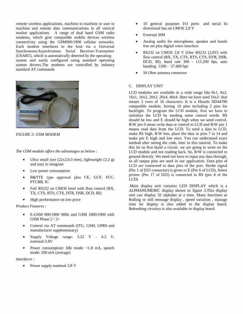
remote wireless applications, machine to machine or user tomachine and remote data communications in all verticalmarket applications. A range of dual band GSM radiomodems, which give compatible mobile devices wirelessconnectivity using the GSM900/1800 cellular networks.Each modem interfaces to the host via a UniversalSynchronous/Asynchronous Serial Receiver-Transmitter(USART), which is automatically detected by the operatingsystem and easily configured using standard operatingsystem drivers.The modems are controlled by industrystandard AT commands
FIGURE 2: GSM MODEM
The GSM module offers the advantages as below :
Ultra small size (22x22x3 mm), lightweight (3.2 g)and easy to integrate
Low power consumption
R&TTE type approval plus CE, GCF, FCC,PTCRB, IC
Full RS232 on CMOS level with flow control (RX,TX, CTS, RTS, CTS, DTR, DSR, DCD, RI)
High performance on low price
Product Features :
E-GSM 900/1800 MHz and GSM 1800/1900 withGSM Phase 2 / 2+
Control via AT commands (ITU, GSM, GPRS andmanufacturer supplementary)
Supply Voltage range: 3.22 V - 4.2 V,nominal:3.8V
Power consumption: Idle mode: <1.8 mA, speechmode: 200 mA (average)
Interfaces :
Power supply nominal 3,8 V
10 general purposes I/O ports and serial bi-directional bus on CMOS 2,8 V
External SIM
Analog audio for microphone, speaker and handsfree set plus digital voice interface
RS232 on CMOS 2,8 V (One RS232 (2,8V) withflow control (RX, TX, CTS, RTS, CTS, DTR, DSR,DCD, RI), baud rate 300 - 115.200 bps, autobauding 1200 - 57.600 bps
50 Ohm antenna connector
DISPLAY UNITC.
LCD modules are available in a wide range like 8x1, 8x2,16x1, 16x2, 20x2, 20x4, 40x4. Here we have used 16x2- thatmeans 2 rows of 16 characters. It is a Hitachi HD44780compatible module, having 16 pins including 2 pins forbacklight. To program the LCD module, first we have toinitialize the LCD by sending some control words. RSshould be low and E should be high when we send control.R/W pin 0 mean write data or control to LCD and R/W pin 1means read data from the LCD. To send a data to LCD,make RS high, R/W low, place the data in pins 7 to 14 andmake pin E high and low once. You can understand exactmethod after seeing the code, later in this tutorial. To makethis let us first build a circuit. we are going to write on theLCD module and not reading back. So, R/W is connected toground directly. We need not have to input any data through,so all output pins are used in our application. Data pins ofLCD are connected to data pins of the port. Strobe signal(Pin 1 of D25 connector) is given to E (Pin 6 of LCD), Selectprinter (Pin 17 of D25) is connected to RS (pin 4 of theLCD)
.Main display unit contains LED DISPLAY which is aALPHANUMERIC display shown in figure 3.This displayunit can display 32 alphabet at a time. Many functions asRolling or still message display , speed variation , managetime for display is also added to the display board.Refreshing circuitry is also available in display board.

FIGURE 3 . ALPHANUMERIC DISPLAY
PULL UP RESISTORS:D.
Pull-up resistors are used in electronic logic circuits toensure that inputs to logic systems settle at expected logiclevels if external devices are disconnected. Pull-up resistorsshown in figure 4 may also be used at the interface betweentwo different types of logic devices, possibly operating atdifferent power supply voltages. The idea of a pull-upresistor is that it weakly "pulls" the voltage of the wire it'sconnected to towards 5V (or whatever voltage represents alogic "high"). However, the resistor is intentionally weak(high-resistance) enough that, if something else stronglypulls the wire toward 0V, the wire will go to 0V. Anexample of something that would strongly pull a wire to 0Vwould be the transistor in an open-collector output.Similarly,pull-down resistors are used to hold the input to a zero (low)value when no other component is driving the input. Theyare used less often than pull-up resistors. Pull-down resistorscan safely be used with CMOS logic gates because the inputsare voltage-controlled. TTL logic inputs that are left un-connected inherently float high, thus they require a muchlower valued pull-down resistor to force the input low. Thisalso consumes more current. For that reason, pull-upresistors are preferred in TTL circuits. Pull-up resistors maybe discrete devices mounted on the same circuit board as thelogic devices. Many microcontrollers intended for embeddedcontrol applications have internal, programmable pull-upresistors for logic inputs so that minimal externalcomponents are needed.Some disadvantages of pull-upresistors are the extra power consumed when current isdrawn through the resistor, and the reduced speed of a pull-up compared to an active current source. Certain logic
families are susceptible to power supply transientsintroduced into logic inputs through pull-up resistors, whichmay force the use of a separate filtered power source for thepull-ups. I²C requires pull-up resistors on its clock (SCL)and data line (SDA) because the pins on the chips are ofopen-collector design.5V power supply for digitalcircuits.This circuit is a small +5V power supply, which isuseful when experimenting with digital electronics. Smallinexpensive wall tranformers with variable output voltageare available from any electronics shop and supermarket.Those transformers are easily available, but usually theirvoltage regulation is very poor, which makes then not veryusable for digital circuit experimenter unless a betterregulation can be achieved in some way. The followingcircuit is the answer to the problem
FIGURE 4: A circuit showing a pull-up resistor (R2)and a pull-down resistor (R1)
POWER SUPPLYE.
This circuit can give +5V output at about 150 mA current,but it can be increased to 1 A when good cooling is added to7805 regulator chip. The circuit has over overload andtherminal protection.
FIGURE 5: Circuit diagram of the power supply.
The capacitors must have enough high voltage rating tosafely handle the input voltage feed to circuit. The circuit isvery easy to build for example into a piece of veroboard
MAX232, MAX232IF. DUAL EIA-232 DRIVERS/RECEIVERS
Meet or Exceed TIA/EIA-232-F and ITURecommendation V.28Operate With Single 5-V Power SupplyOperate Up to 120 kbit/sTwo Drivers and Two Receivers±30-V Input LevelsLow Supply Current . . . 8 mA TypicalDesigned to be Interchangeable With MaximMAX232ESD Protection Exceeds JESD 22– 2000-V Human-Body Model (A114-A)
The MAX232 is a dual driver/receiver that includes acapacitive voltage generator to supply EIA-232 voltagelevels from a single 5-V supply. Each receiver converts EIA-232 inputs to 5-V TTL/CMOS levels. These receivers have atypical threshold of 1.3 V and a typical hysteresis of 0.5 V,and can accept ±30-V inputs. Each driver convertsTTL/CMOS input levels into EIA-232 levels. The driver,receiver, and voltage-generator functions are available ascells in the Texas Instruments LinASIC library.
SOFTWARES USEDIII.
EXPRESS PCBA.
Express PCB is a free PCB software and is a snap to learnand use. For the first time, designing circuit boards is simplefor the beginner and efficient for the professional. The boardmanufacturing service makes top quality two and four layerPCBs.
Embedded CB.
Use of embedded processors in passenger cars, mobilephones, medical equipment, aerospace systems and defensesystems is widespread, and even everyday domesticappliances such as dish washers, televisions, washingmachines and video recorders now include at least one suchdevice. There is a large - and growing - internationaldemand for programmers with 'embedded' skills, and manydesktop developers are starting to move into this importantarea.Because most embedded projects have severe costconstraints, they tend to use low-cost processors like the8051 family of devices considered in this book. Thesepopular chips have very limited resources available: mostsuch devices have around 256 bytes (not megabytes!) of
RAM, and the available processor power is around 1000times less than that of a desktop processor. As a result,developing embedded software presents significant newchallenges, even for experienced desktop programmers.
KEILC.
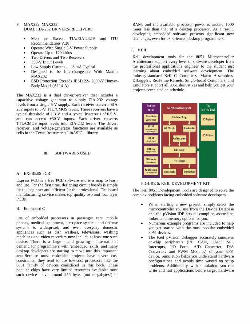
Keil development tools for the 8051 MicrocontrollerArchitecture support every level of software developer fromthe professional applications engineer to the student justlearning about embedded software development. Theindustry-standard Keil C Compilers, Macro Assemblers,Debuggers, Real-time Kernels, Single-board Computers, andEmulators support all 8051 derivatives and help you get yourprojects completed on schedule.
FIGURE 6: KEIL DEVELOPMENT KIT
The Keil 8051 Development Tools are designed to solve thecomplex problems facing embedded software developers.
When starting a new project, simply select themicrocontroller you use from the Device Databaseand the µVision IDE sets all compiler, assembler,linker, and memory options for you.Numerous example programs are included to helpyou get started with the most popular embedded8051 devices.The Keil µVision Debugger accurately simulateson-chip peripherals (I²C, CAN, UART, SPI,Interrupts, I/O Ports, A/D Converter, D/AConverter, and PWM Modules) of your 8051device. Simulation helps you understand hardwareconfigurations and avoids time wasted on setupproblems. Additionally, with simulation, you canwrite and test applications before target hardware

is available.When you are ready to begin testing your softwareapplication with target hardware, use the MON51,MON390, MONADI, or FlashMON51 TargetMonitors, the ISD51 In-System Debugger, or theULINK USB-JTAG Adapter to download and testprogram code on your target system.
CIRCUIT DIAGRAMIV.
FIGURE 7: CIRCUIT DIAGRAM OF µC PANEL
FIGURE 8: CIRCUIT DIAGRAM OF BUFFER 74LS154PANEL
FIGURE 9: CIRCUIT DIAGRAM OFMICROCONTROLLER PANEL WITH DRIVER CIRCUIT

CONCLUSIONV.
By introducing the concept of wireless technology in thefield of communication we can make our communicationmore efficient and faster , with greater efficiency we candisplay the messages and with less errors andmaintenance. This model can be used very efficiently inestablishments like chain restaurants wherein the orderand special discounts can be displayed at all branchessimultaneously, in colleges wherein students and stavescan be informed simultaneously in no time. It can be setup at public transport places like railways , bus station ,airport and also at roadside for traffic control and inemergency situations, it is cost efficient system and veryeasy to handle, a single person can handle all the workwith just a message. PC with administrator has been usedfor ease of message sending and keeping record
ACKNOWLEDGMENT
This seminar report would not have seen the light of theday without Mrs Gaikwad ma’am, our project guide. Weare highly grateful and obliged for her guidance andinstructions which made this report possible. Had it notbeen her concern and help at every stage of the preparationof the seminar, we would not have been able to come to theconclusion of the seminar report. it was because of herhelp and support that we could successfully complete thisreport.
REFERENCES
[1] Books: The 8051 Microcontroller and System - Janice Gillispie Mazidi - Rolin D. McKinlay - Muhammad Ali Mazidi
[2] Books: ]GSM and Personal Communications Handbook
- Siegmund Redl, - Matthias Weber - Malcolm W. Oliphant
[3] Web Site - http://burnsidetelecom.com/whitepapers/gsm.pdf [4] Web site - http://www.cisco.com [5] Web site - http://www.alldatasheets.com [6] Web Site - http://www.atmel.com/dyn/resources/prod _documents/doc0265.pdf [7] Web Site - http://www.robotroom.com/AlphanumericDisplay.html [8] Web Site - http://pdfserv.maxim-ic.com/en/an/AN83.pdf [9] Web Site - http://www.beyondlogic.org/serial/serial.pdf [10] Web Site - http://www.directindustry.com/industrial[11pdf – Philips semiconductors/80c51 8 bit microcontroller data sheets