Wireless Communications · Full-duplex Half-duplex Simplex. Duplexing l Frequency division...
64
Electrical & Computer Engineering Wireless Communications Multiple Access Hamid Bahrami
Transcript of Wireless Communications · Full-duplex Half-duplex Simplex. Duplexing l Frequency division...

Electrical & Computer Engineering
Wireless Communications
Multiple Access
Hamid Bahrami

Communication System Block Diagram

Duplexing
l Duplexing: transmit and receive at the same time l Example: telephone, how about walkie-talkie
Terminal A
Terminal B
Terminal A
Terminal B
Terminal A
Terminal B
Full-duplex
Half-duplex
Simplex

Duplexingl Frequency division duplexing (FDD)
l Multiplexes the Tx and Rx in one time slot in which transmission and reception is on 2 different frequencies
l It provides simultaneous transmission channels for mobile/base station (forward and reverse channels)
l At the base station, separate transmit and receive antennas are used to accommodate the two separate channels
l At the mobile unit, a single antenna (with duplexer) is used to enable transmission and reception
l To facilitate FDD, sufficient frequency isolation of the transmit and receive frequencies is necessary

Duplexing
l Time division duplexing (TDD)l Multiplexes the Tx & Rx in one frequency at different time
slots
l Ex: in a simple 2-way radio where a button is pressed to talk and released to listen
l Only possible for digital transmission
Time Division Duplexing
Time
Am
plitu
de
T TR R
Multiplexing
l Multiplexing (channelization) is the process of simultaneously transmitting several information signals using a single communication channel

Frequency Division Multiplexing
l The available bandwidth is divided into non-overlapping frequency slots and each message is assigned a frequency slot within the available band
l Signals are transmitted by different frequency bands and then added together to form a baseband signal
l The signals are narrowband and frequency limited
Frequency Band 1
Frequency Band 2
Frequency Band N
f0
f2
fN-2
fN-1
f1
f3
Time
Freq
uenc
y

Time Division Multiplexing
l Digital signals from several sources are multiplexed in time and transmitted over a single communication channel
l The communication channel is divided into frames; each frame is further segmented into slots; each user is assigned a slot (or channel) within each time frame
l Only for digital communication
Slot1
Slot2
SlotNs1 s2 sk . . .
FRAME
. . .
Sync word Information or data word
s1 s2 . . .SlotN. . .

Code Division Multiplexing (CDM)
l Multiple signals are transmitted simultaneously on the same time and same frequency
l Each signal is assigned a distinct code sequencel The code sequences (spreading codes) are orthogonal (or
almost orthogonal)
!

Example of orthogonal codes
Code 1 = {1, 1, 1, 1}
Code 2 = {1, 1, -1, -1}
Code 3 = {1, -1, -1, 1}
Code 4 = {1, -1, 1, -1}

FDM/TDM/CDM

Spatial Multiplexing
l Multiplexing in space using multiple antenna at the Tx and Rx

Wavelength Division Multiplexing
l Optical communication

Multiple Access
l Multiple access: used to allow many mobile users to share simultaneously a finite amount of radio spectruml Frequency division multiple access (FDMA)l Time division multiple access (TDMA)l Code division multiple access (CDMA)l Space Division Multiple Access (SDMA)l Demand Access Multiple Access (DAMA)l Random Access Multiple Access (RAMA)l Hybrid Multiple Accesses

Multiple Access
l To transmit multiple signals in a point-to-point communication system, we use multiplexing.
l In a multi-user system with multiple receivers (a point-to-multipoint or broadcast system), a system with multiple transmitters (a multipoint-to-point or multi-access system), or a system composed of many users communicating directly with each other (a multipoint-to-multipoint system), we can use the same concept to transmit these multiple signals. This is called multiple access.

Multiple Access
l Multiple access: used to allow many users to share simultaneously a finite amount of radio spectruml Frequency division multiple access (FDMA)l Time division multiple access (TDMA)l Code division multiple access (CDMA)l Space Division Multiple Access (SDMA)l These are sometimes called channelization
protocols. These are contentionless protocols. Good for circuit switch.
l Random Access Multiple Access (RAMA): Less coordinated and controlled. Contention based protocols. Good for packet switch.
l Hybrid Multiple Accesses

Multiple Access
Multiple Access Protocol
Contention(Random Access)
Contentionless(Scheduling Access)
CDMA
Fixed Assigned
Demand Assigned
FDMATDMA
PollingToken Passing
Repeated Random Access
ALOHASlotted ALOHA
Random Access w/reservation
ImplicitExplicit

Frequency Division Multiple Access
l Individual frequencies are assigned to individual users on demand for the duration of callsl Frequency distances are far enough à no interferencel When the call is finished à the channel is released and
available for a new calll If the transmission path deterioratesà switches the system
to another channel
1 2 n
B
FRAME
Guard band (at the edges & between) tominimize crosstalk
!

Frequency Division Multiple Access
l The FDMA channel carries only one phone circuit at a time
l If a channel is not in use, then it sits idle and cannot be used by other users à the waste of bandwidth
l After the assignment of a voice channel, the base station and the mobile transmit simultaneously and continuously
l The bandwidths of FDMA channels are relatively narrow à narrowband systems
l The symbol time of a signal is large as compared to the average delay spread à little or no equalization

Frequency Division Multiple Accessl Low complexity à but it is changing l Fewer bits are needed for synchronization as frame
bits l Higher cell sit system cost ß the need of bandpass
filters and single channel per carrier design l Duplexers ß both tx and rx operate at the same time l Require tight RF filter to minimize the adjacent
channel interferencel Orthogonal FDMA (OFDMA) is the multiple access
scheme for 4G systems (LTE and IEEE 802.16/WiMAX)
Frequency Division Multiple Access
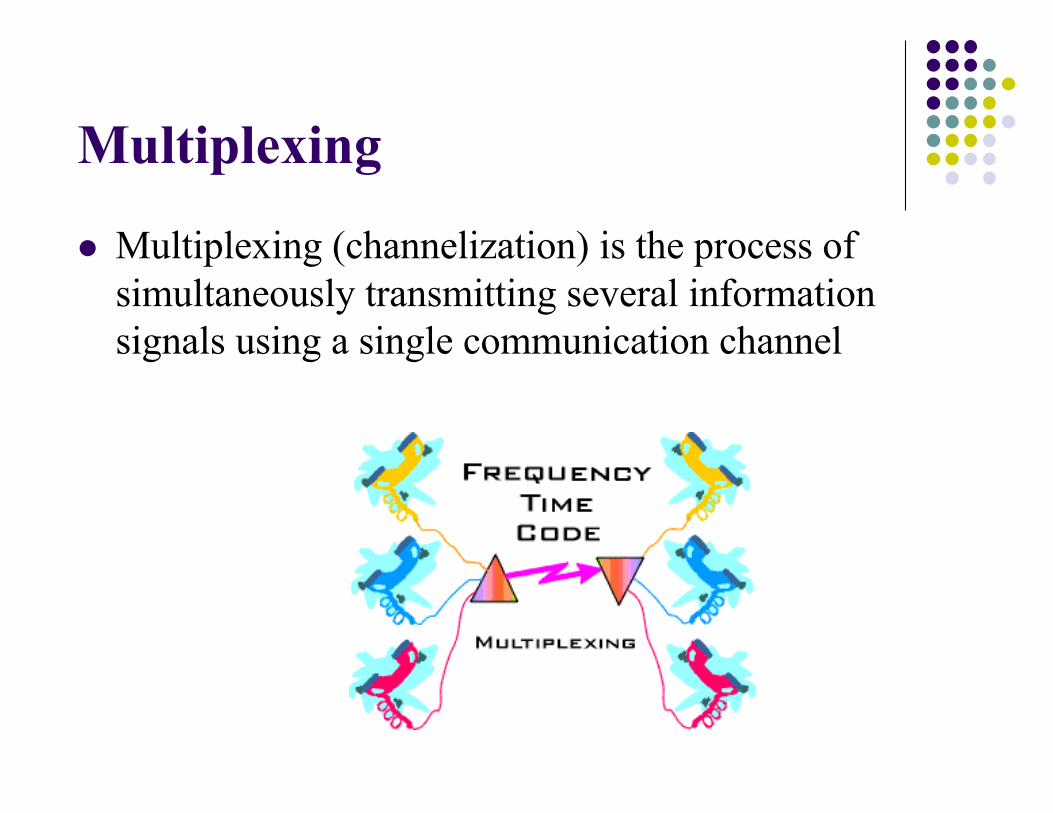
l Guard band Bguard: allocated at the edge of the allocated spectrum band
l Channel bandwidth: Bc
l The total spectrum allocation: Bt
l The number of channels: N
Channel1
Channel2 ...... Channel
Ns
Bs
BcBg MHz
C
guardt
BBB
N2-
=

Practice l Design a Frequency Division Multiplex (FDM) signal set
consisting five voice channels, each in the frequency range 300 to 3400 Hz. The multiplexed composite is to occupy the spectral region from 30k to 50 kHz. Decide the allocating frequency bands for each channel by using the maximum guard band frequency.
The voice channel bandwidth is 3100 Hz. The maximum guard bandwidth is Channel 1: 30000 ~ 33100 Hz and Guard band: 33100 ~ 34000 Hz Channel 2: 34000 ~ 37100 Hz and Guard band: 37100 ~ 38000 Hz Channel 3: 38000 ~ 41100 Hz and Guard band: 41100 ~ 41000 Hz Channel 4: 42000 ~ 45100 Hz and Guard band: 45100 ~ 46000 Hz Channel 5: 46000 ~ 49100 Hz and Guard band: 49100 ~ 50000 Hz
( ) HzGuardGuard 900300005000053100 £Þ-£´+

Frequency Division Multiple Access
l Example: AMPS (Advanced Mobile Phone System)l Developed by Bell Labs and introduced in 1978.l 1G, Analog, 800MHz FM bandl Each AMPS channel has a one way bandwidth of 30KHz (60KHz each duplex channel)l 416 channels in 824-849MHz band (uplink) and 416 channels in 869-894MHz band (downlink)

Example 9.2, page 452l If a US AMPS (advanced mobile phone system) cellular
operator is allocated 12.5 MHz for each simplex band, and if Bguard is 10 KHz, and Bc is 30 kHz, find the number of channels available in an FDMA system.
4161030
10102105.123
36
=´
´´-´=N
Time Division Multiple Access
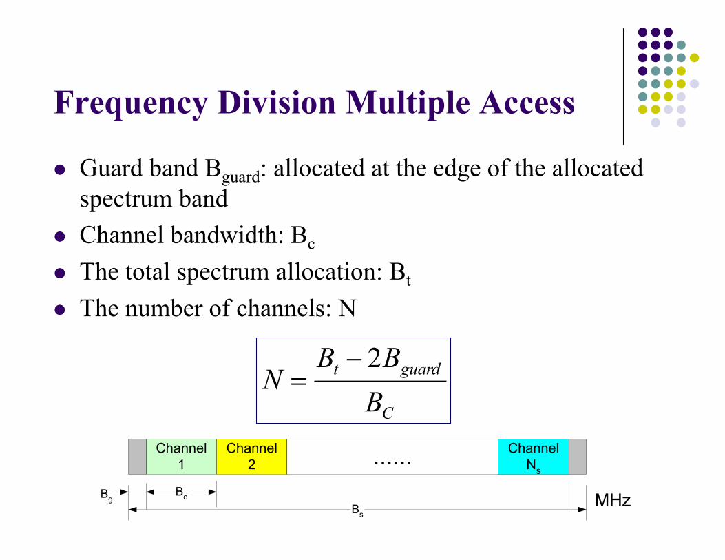
l Divide the radio spectrum into time slotsl In each slot, only one user is allowed to either transmit or
receivel Buffer-and-burst method à non-continuous transmission
(digital communication)
Control Bits
Slot 1
Trail BitsInformation Data
Slot 2 Slot 3 Slot N
Guard BitsInformation DataTrail Bits Sync. Bits
One TDMA Frame

Time Division Multiple Access
l Shares a signal carrier frequency with several users, where each user makes use of non-overlapping time slots
l Data transmission is not continuous, but occurs in bursts à low battery consumption
l Handoff process is simple ß discontinuous transmission l Duplex is not required l Adaptive equalization is necessary ß high data rate l The guard time should be minimized l High synchronization

Time Division Multiple Access
l IS-54l The original TDMA format for AMPSl By dividing a 30-kHz channel into 3 time slots, enabling 3 different
users to occupy it at same timel Provides a 3-fold increase in traffic capacity relative to AMPS, given
the same bandwidth allocationl A second phase of the IS-54 standard provides for 6 (instead of 3)
TDMA user channels in each 30 kHz radio channel
l IS-136 (also called called D-AMPS)l Enhanced TDMA with special control channels to allow short
message service, battery life extension, other features, 6 timeslots, three users occupy in rotation

Time Division Multiple Access
l GSM (Global System for Mobile)l Pan-European digital cellular standard to replace six
incompatible analog cellular systems then in use in different geographic areas in early 80’s
l Employing TDMA and each radio channel carries 8 timeslots (8 speech channels) and the radio channel bandwidth (for all 8 channels) is almost 270Kbps.
l Freq. band 850MHz or 1900MHz (in many countries 900 and 1800MHz)
l AT&T network is mainly a GSM based network.

Time Division Multiple Access l Efficiency of TDMA
l A measure of the percentage of transmitted data that contains information as opposed to providing overhead for the access scheme
RTbbNbNbNbNb
bb
fT
grgtptrrOH
T
OH
=
+++=
´÷÷ø
öççè
æ-= %1001h
bOH =overhead bits per frame Tf: frame durationNr = # of reference burst per frame R: System bit rateNt = # of trail (preamble) burst per framebr = # of overhead bits per reference burstbp = # of overhead bits per preamblebg = # of equivalent bits in each guard time interval

Time Division Multiple Access
l Number of channels in TDMA system
( )C
guardt
BBBm
N2-
=
m: the maximum number of TDMA users supported on each radio channel
l Example 9.4: If GSM uses a frame structure where each frame consists of eight time slots, and each time slot contains 156.25 bits, and data is transmitted at 270.833 kpbs in the channel. Find (1) the time duration of a bit (2) the time duration of a slot, (3) the time duration of a frame, and (4) how long must a user occupying a single time slot wait between two successive transmissions.

Example 9.4
4.615ms : timeWaiting615.48:frame a ofduration timeThe
577.025.156:slot a ofduration timeThe
692.3833.270
1 :bit a ofduration timeThe
msTTmsTT
sT
slots
bslot
b
=´==´=
== µ
Code Division Multiple Access
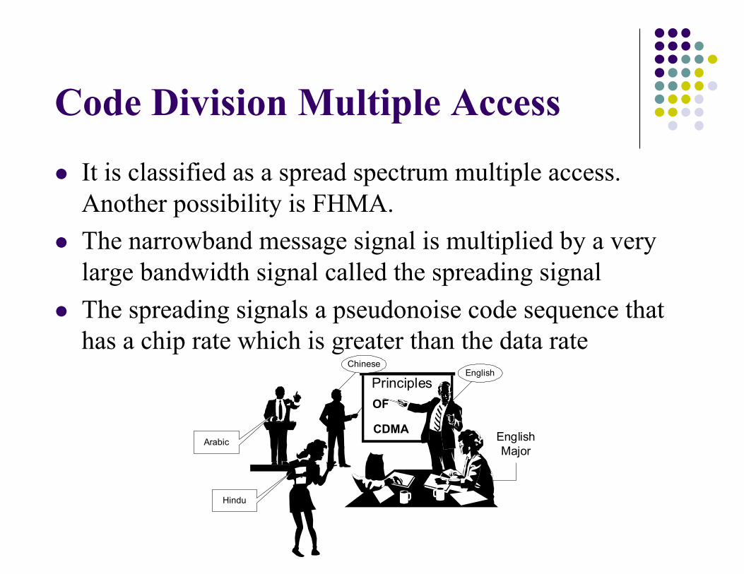
l It is classified as a spread spectrum multiple access. Another possibility is FHMA.
l The narrowband message signal is multiplied by a very large bandwidth signal called the spreading signal
l The spreading signals a pseudonoise code sequence that has a chip rate which is greater than the data rate
CDMA
PrinciplesOF
EnglishChinese
Hindu
Arabic EnglishMajor

Code Division Multiple Access
l Many users of a CDMA system share the same frequency, either TDD or FDD
l Soft capacity limit à increasing the number of users raises the noise floor in a linear manner
l Multiple fading might be substantially reduced ß the signal is spread over a large spectrum
l Channel data rates are high à the symbol duration is short and less then the channel delay spread
l RAKE receiver can be usedl Self-jamming is a problem ß not perfectly orthogonal l Near-far problem
Code Division Multiple Access
l Reverse Link (from mobile unit to base station)l Near-far problem
l The power of each user do not appear equal at the base stationl Many mobile users share the same channel
l Power control:l To maximize the total user capacity l To minimize power consumption of portable units
l Forward Link (from base station to mobile unit) l Link does not suffer much from near-far problem since all cell
signals can be received at the mobile with equal powerl When at excessive intercell interference, the power control can
be applied by increasing the power to the mobile

Code Division Multiple Access
l Advantagesl Voice Activities Cycles (35% talking, 65% listening)l Improved call qualityl No Equalizer Needed (only correlator needed)l No hard handoffl No guard time l Less fadingl No frequency management needed l Capacity advantage l Enhanced privacy l Coexistence l Simple system planning

Code Division Multiple Access
l IS-95 (Interim Standard 95) also called cdmaOnel Qualcomm, a San Diego-based companyl IS-95 was used as a 2G standardl Each channel bandwidth was 1.2288 MHz (much
larger than narrowband)l Offer greater traffic capacity than GSM
l CDMA 2000 (3G)l Supports data rate of up to 153Kbpsl Channel bandwidth is 1.25MHzl Verizon and Sprint Nextel networks
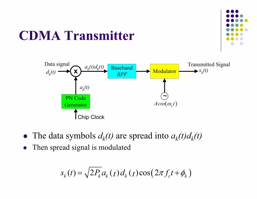
CDMA Transmitter
l The data symbols dk(t) are spread into ak(t)dk(t)l Then spread signal is modulated
x BasebandBPF
PN CodeGenerator
Data signal Transmitted Signalxk(t)
Chip Clock
~ak(t)
dk(t)ak(t)dk(t) Modulator
( )cAcos tw
( ) ( ) ( )( ) 2 cos 2k k k k c ks t P a d f tt t p f= +

(CDMA) Channel
hk(t)sk(t) yk(t)
[ ]1
( ) klL j
klk kll
th t e ytb d=
-= å
( ) ( )
( ) ( ) ( ) [ ]
( ) ( ) ( )1
1
( )
- - -2 cos
- -2 cos
kl
kk
L jk k klk kl k k c k
lL
kl klk kl k k c kll
ty t h s d
t t tP a d t e d
t tP a d t
y
t tt
t t tb w f d t
t tb w q
¥-¥
¥-¥
=
=
-= ò
= +å ò
= +å

CDMA Receiver
l Detection accomplished by de-modulating & de-spreading l This involves the correlation of the received signal with the
delayed version of the spreading signal (despreading operation)
l In other words, the received signal is multiplied again by a synchronized version of the PN code
( )0bT dt×ò kls
( )k da t T-
( )r t
2 cos ( )k c kP tw q+
Demodulator( )y t Decision
Device

Performance Analysis for Multiple users
( )
( ) ( ) ( )1
1 1
( ) ( )
- -2 cos 2 ( )
K
k kkK L
kl klk kl k k c klk l
r t y n tt
t tP a d f t n tt tb p q
=
= =
= +å
= + +å å
ò
( )
( ) ( ) ( )1
1 1
( ) ( )
- -2 cos 2 ( )
K
k kkK L
kl klk kl k k c klk l
r t y n tt
t tP a d f t n tt tb p q
=
= =
= +å
= + +å å

Performance Analysis l Assuming the first user is desired
( ) ( ) ( )( 1)1 1 cos 2i Tb
ciTbz r a f t dtt t p+= ò
( ) ( ) ( )1 10 cos 2Tbcz r a f t dtt t p= ò
( ) ( ) ( ) ( ) ( )
( ) ( ) ( )
1 101 1
10
- -2 cos cos
cos
K L Tbkl kli k kl k k c c kl
k l
Tbc
t tz P a a d t tt
n a t dtt t
t tb w w q
w
= == +å å ò
+ ò

Space Division Multiple Access (SDMA)
l Separating the signals of multiple users using beamforming

Hybrid FDMA/CDMA (FCDMA)
l Available spectrum is divided into subbandsl Each subband is then considered as a CDMA systeml It is the principle of multi-carrier CDMA (MC-CDMA)

Hybrid Direct Sequence/Frequency Hopping Multiple Access (DS/FHSS)
l Signal of each user is a DS signal whose center frequency hops periodically in a pseudo-random fashion.
l Avoids near-far problem, soft hand-off is not possible

Other Hybrid Techniques
l Time Division CDMA (TCDMA)l Different spreading codes are assigned to different cellsl Within each cell, only one user is allocated a particular time slot
such that only one user is transmitting in each cell at one slot
l Time Division Frequency Hopping (TDFH)l At the start of a new TDMA frame, the user hops to a new
channell This avoids severe fades or erasure in any particular channell The user is allowed to hop according to a predefined sequencel TXs are made to transmit on different frequencies at different
times

Orthogonal Frequency Division Multiplexing (OFDM)l Similar to FDM by using three principles
l Multirate, multisymbol and multicarrier l Distribute the data over a large number of carrier allows
smaller transmission rate, e.g., bigger symbol duration l Reduce the effect of ISI l No/Less frequency selective fading l Possible guard interval between symbols
l Orthogonal relationship between the subcarrier signals allow subcarriers to overlap each other without interference l No cross talk between carriers l No need for inter-carrier guard band

OFDM Case Study – Tx
http://upload.wikimedia.org/wikipedia/commons/4/4e/OFDM_transmitter_ideal.png
Wireless Local Area Network
Data à Serial to Parallel à Modulation à IFFT à Parallel to Serial à Guard à Mod

OFDM Case Study – Rx
Wireless Local Area Network
Demod à Guard removal à Serial to Parallel à FFT à DeMod à Parallel to Serial à Data

Orthogonal Frequency Division Multiple Access (OFDMA)

Multicarrier DS-CDMA
l Statement of problems l Variety of services, including voice, data, image and
video l DS-CDMA suffers ISI and Multi-user Interference
(MUI) l OFDM has the potential benefit
l Multicarrier DS-CDMAl Marries the best of the OFDM and DS-CDMA l 4G

Random Access
l In packet radio (PR), many users attempt to access a single channel in an uncoordinated (or minimally coordinated manner).
l Collision can happen and is detected by the basestation (access point or AP). The AP broadcasts an ACK or a NACK signal for successful and unsuccessful reception of user’s data.
l The users use a contention technique to transmit on a common channel.
l PR is easy to implement but has low spectral efficiency and may cause delay. It is only used for transmission of data (less sensitive to delay) and not in voice systems.

Random Access Protocols
l Pure ALOHA: a user accesses a channel as soon as a packet is ready to be transmitted. After transmission the user wait for ACK. (Developed in University of Hawaii in early 70’s)
l In case of collision (when NACK is received), the terminal waits for a random period of time and then retransmits the same packet.
l There is almost no timing in the system.l Very easy to implement but large delay especially when
the number of users is large.

Random Access Protocols
l Pure ALOHA Sending a packet
Waiting for ACK
ACK received?
Randomly selected a delay
Continue the next packet
Yes
No

Random Access Protocols
l Slotted ALOHA: Time is divided into equal time-slots. All users have synchronized clocks.
l If a user has a packet to transmit, its transmission is done only at the beginning of each time-slot. The rest of the protocol is similar to ALOHA.
l This prevents partial collision and improves the throughput (reduces delay).
l Still for large number of users, the delay can be high.

Random Access Protocols
l Slotted ALOHA

Random Access Protocolsl In pure and slotted ALOHA protocols the users don’t listen to
the channel.l By listening to the channel before transmission, greater
efficiency is achieved.l Carrier Sense Multiple Access (CSMA): A users with a packet
to transmit, constantly monitor the channel. If the channel is idle, the user transmits.
l CSMA with Collision Detection (CD): The user continues listening to the channel during its own transmission. If senses a collision, it stops transmission.
l CSMA with Collision Avoidance (CA): If the channel is busy, the user waits (backs off) for a random amount of time (why random?).
Random Access Protocols
Terminal A
AP
Terminal B
Terminal C
Backoff Intervel Packet Arrival Residual Backof Time
DIFS
Packet A
SIFS
ACK ACK
SIFS
Packet B
DIFS
Packet C
DIFS
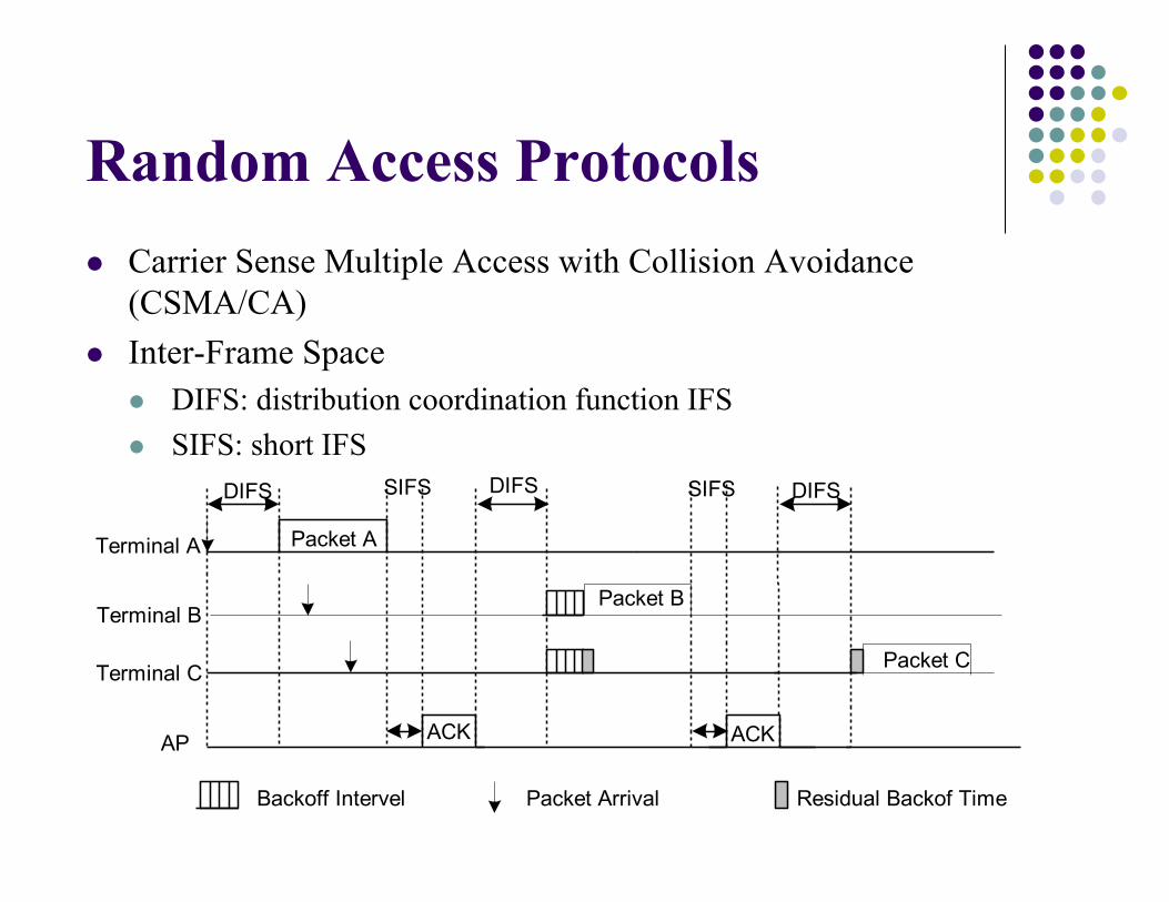
l Carrier Sense Multiple Access with Collision Avoidance (CSMA/CA)
l Inter-Frame Spacel DIFS: distribution coordination function IFSl SIFS: short IFS

Random Access Protocolsl Reservation Protocol: The transmission time is divided
into slots. Unlike previous contention based random access protocols, here a user can reserve slots for transmission.
l One can think of it as a middle ground between multiple access schemes and other random access protocols.
l Specially good for transmission of high priority packets and for transmission without interrupt (continuous transmission).
l Reservation and some other protocols (such as Polling) are sometimes called controlled-access protocols.
l WiFi uses CSMA/CA with reservation.

Capture Effect and Hidden Terminal
l Often the closest transmitter is able to capture a receiver because of small path loss. This is called near-far (or capture) effect.
l Good because many packets of this terminals arrive at the receiver despite collision.
l Bad because a strong transmitter may make it impossible for the receiver to detect a much weaker transmitter which is attempting to communicate to the same receiver (hidden terminal).
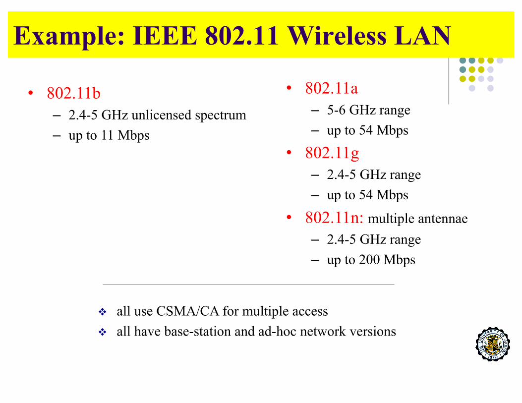
Example: IEEE 802.11 Wireless LAN
• 802.11b– 2.4-5 GHz unlicensed spectrum– up to 11 Mbps
• 802.11a– 5-6 GHz range– up to 54 Mbps
• 802.11g – 2.4-5 GHz range– up to 54 Mbps
• 802.11n: multiple antennae– 2.4-5 GHz range– up to 200 Mbps
v all use CSMA/CA for multiple accessv all have base-station and ad-hoc network versions

80211. Wireless LAN Architecture
v wireless host communicates with base station§ base station = access point
(AP)v Basic Service Set (BSS) (aka
“cell”) in infrastructure mode contains:§ wireless hosts§ access point (AP): base
station§ ad hoc mode: hosts only
BSS 1
BSS 2
Internet
hub, switchor routerAP
AP

IEEE 802.11 Multiple Access
• avoid collisions: 2+ nodes transmitting at same time
• 802.11: CSMA - sense before transmitting– don’t collide with ongoing transmission by other node
• 802.11: no collision detection as in Ethernet!– difficult to receive (sense collisions) when transmitting due to weak
received signals (fading)– can’t sense all collisions in any case: hidden terminal, fading– goal: avoid collisions: CSMA/C(ollision)A(voidance)

IEEE 802.11 MAC Protocol: CSMA/CA
802.11 sender1 if sense channel idle for DIFS then
transmit entire frame (no CD)2 if sense channel busy then
start random backoff timetimer counts down while channel idletransmit when timer expiresif no ACK, increase random backoff interval,
repeat 2
802.11 receiver- if frame received OK
return ACK after SIFS (ACK needed due to hidden terminal problem)
sender receiver
DIFS
data
SIFS
ACK

IEEE 802.11 MAC Protocol: CSMA/CA
idea: allow sender to “reserve” channel rather than random access of data frames: avoid collisions of long data frames
• sender first transmits small request-to-send (RTS) packets to BS using CSMA– RTSs may still collide with each other (but they’re short)
• BS broadcasts clear-to-send CTS in response to RTS• CTS heard by all nodes
– sender transmits data frame– other stations defer transmissions
avoid data frame collisions completely using small reservation packets!


![FEATURES & BENEFITS€¦ · 6' [1.8m] GB, GBA 12" [305mm] 18" [457mm] 30" [760mm] 2 Duplex 3 Duplex 4 Duplex 5 Duplex 6 Duplex • Hard-Wired models • Cord-Ended models CUSTOM PLUGMOLD](https://static.fdocuments.in/doc/165x107/5fc2103c504884668467a733/features-benefits-6-18m-gb-gba-12-305mm-18-457mm-30.jpg)