Wireless CommuniCation -...
64
Wireless CommuniCation unit 3
Transcript of Wireless CommuniCation -...

Wireless CommuniCation unit 3

unit iiiWireless transCeiVers

Structure of a wireless communication link

• Information source
– The information source provides an analog source signal
and feeds it into the source ADC, where the signal is
converted into a stream of digital data at a certain
sampling rate and resolution.
• Source coder
– This reduces the amount of source data to be transmitted.
– Datas are encrypted in order to prevent unauthorized
listening
– GSM speech coder reduces the source data rate from 64
kbit/s to 13 kbit/s
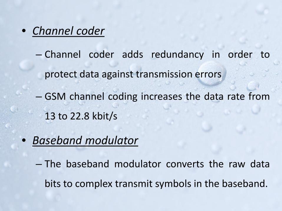
• Channel coder
– Channel coder adds redundancy in order to
protect data against transmission errors
– GSM channel coding increases the data rate from
13 to 22.8 kbit/s
• Baseband modulator
– The baseband modulator converts the raw data
bits to complex transmit symbols in the baseband.
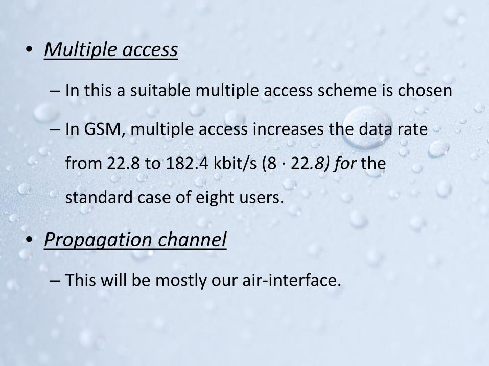
• Multiple access
– In this a suitable multiple access scheme is chosen
– In GSM, multiple access increases the data rate
from 22.8 to 182.4 kbit/s (8 · 22.8) for the
standard case of eight users.
• Propagation channel
– This will be mostly our air-interface.

• Diversity combiner
– For negating the multipath propagation we use
diversity techniques for reception.
– It receives the time delayed signals and combine them
to form an effective output
• Separation
– In this we separate the multiple accessed signals.
– For GSM each of the 8 user’s data will be separated.

• Equalizer
– Equalization compensates for intersymbol
interference (ISI)
• Channel decoder
– This is used to detect or correct the errors
introduced by the channel.
– All the redundant bits added during channel
encoding will be removed.

• Source Decoder
– The source decoder reconstructs the source signal
from the rules of source coding
– The data are transferred to the DAC, which
converts the transmitted information into an
analog signal and hands it over to the information
sink.

Binary FrequenCy shiFt Keying

Binary Frequency Shift Keying
• BFSK uses a pair of discrete frequencies to
transmit binary data.
• The frequency of a constant amplitude carrier
signal is switched between two values
corresponding to a binary 1 or 0

Method 1

VCONRZ Encoder
Binary data
FSK signal
Method 2


0 1 0 1

Spectrum and Bandwidth
• FSK signal consists of discrete frequencycomponents at fc, fc + n π f, fc-n π f
• BFSK = 2Δf+ 2B
– B is the bandwidth of the digital baseband signal.

Coherent Receiver
Regenerated Carrier

• The carrier used in the transmitter was regenerated
by the Carrier Recovery circuit.
• Then they are multiplied with the incoming FSK
signal.
• Then the high frequency components are filtered out
and only the low frequency message is passed
though.
• Threshold comparator will decide whether the
received signal is logic 1 or a 0

Non-Coherent Receiver

• Extracting the same Carrier from the FSK signal will
not be accurate , and it take lot of effort to do that.
• To avoid this we use Non Coherent detection, where
we don’t need any information about the original
carrier.
• The receiver consists of a pair of matched filters,
upper filter is matched to the FSK signal of frequency
fH and the lower filter is matched to the frequency fL
• Depending on the magnitude of the envelope
detector output, the comparator decides
whether the data bit was a 1 or 0.

qudrature phase shiFt Keying

qpsK
• 2 bits are combined in a single symbol.
• It is represented by carriers with 4 differentphases.
• QPSK has twice the bandwidth efficiency ofBPSK.

Es – Amplitude of digital symbol
Ts - duration of symbol
Tb- duration of a single bit
• For QPSK Ts = 2 Tb
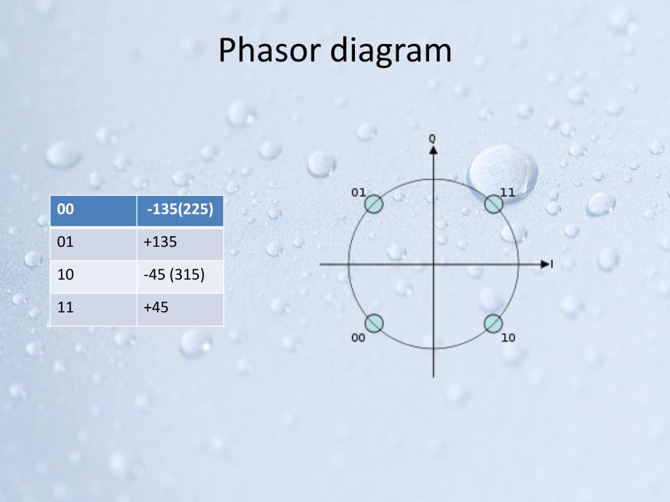
Phasor diagram
00 -135(225)
01 +135
10 -45 (315)
11 +45

QPSK Transmitter Block
NRZ Encoder
Data Signal
I- Channel
Q- Channel

• The input to the system is a binary message
stream has bit rate Rb
• The NRZ Encoder will convert the unipolar
message to bipolar bit sequence.
• The serial to parallel convertor will split the
stream of bits into two separate data streams.
• They are provided to the I-channel and Q-
Channel.

• The bit stream ml (t) is called the "even" stream
and mQ (t) is called the "odd" stream
• The oscillator produces a high frequency carrier.
• The 90o phase shifter will produce an exactly out
of phase signal to that of the carrier.
• The two binary sequences are separately
modulated by two carriers
• The two modulated signals are summed to
produce a QPSK signal.
• The filter at the output of the modulator confines
the power spectrum of the QPSK signal within the
allocated band.
• This prevents spill-over of signal energy into
adjacent channels and also removes out-of-band
spurious signals generated during the modulation
process

QPSK- Waveforms

Receiver

• A carrier recovery is used to estimate the
frequency and phase of a received
signal's carrier.
• The incoming signal is split into two parts, and
each part is coherently demodulated using the in-
phase and quadrature carriers.
• The decision making device is used to regenerate
digital signals. It uses a threshold level to
distinguish between “0” & “1”

oFFset qpsK

Offset QPSK
• In QPSK phase shift of π radians will cause the
amplitude to fluctuations.
• This will lead to generation of side lobes and
spectral widening.
• To reduce this 180o phase shift we use O-QPSK
• In this we have only 90o shifts.
• This is achieved by delaying one channel by Tb sec

• In QPSK the even and odd bit streams occur at the
same time instants.
• But in OQPSK signaling, the even and odd bit streams,
mI (t) and mQ(t) are offset in their relative alignment
by one bit period (half-symbol period).
• Because of this at any given time only one of the two
bit streams can change values.
• So the maximum phase shift of the transmitted signal
at any given time is limited to ±90°

QPSK
O-QPSK

π/4 qpsK

π/4 QPSK
• In π/4 QPSK the maximum phase change is
limited to ±135°.
• So it has less amplitude fluctuations than QPSK.
• It can be detected non coherently .
• The phase shift between successive symbols is an
integer multiple of π /4 radians
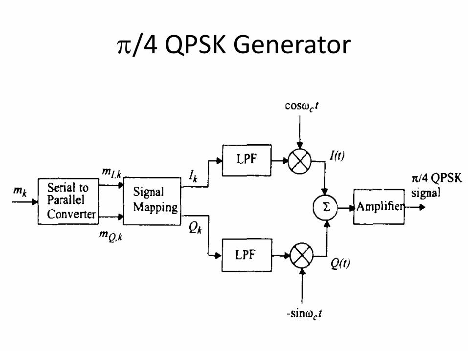
π/4 QPSK Generator
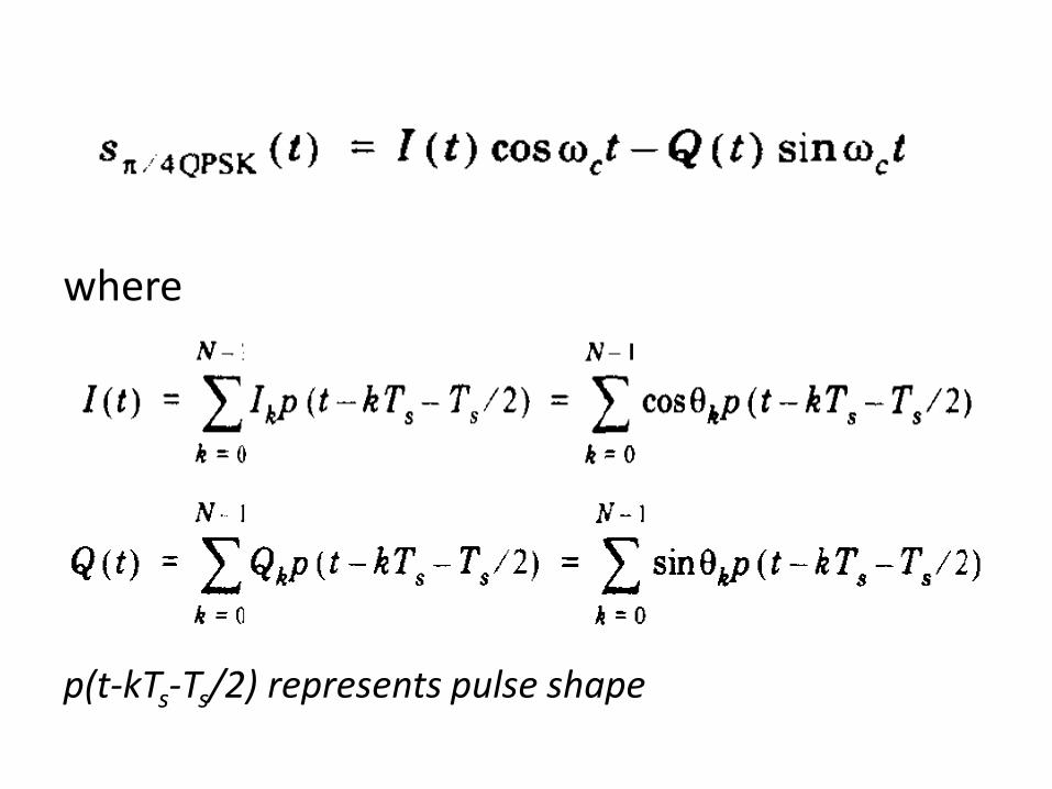
where
p(t-kTs-Ts/2) represents pulse shape


MINIMUM SHIFT KEYING

Intro….
• QPSK results in larger side lobes due to the phase
change of 900 or 1800. .
• So to reduce this we use MSK, where the peak
deviation is ¼ of bit rate.
• MSK is closely related to OQPSK, where we
replace rectangular pulses by sinusoidal pulses.
• Modulation index of MSK is 0.5

MSK Transmitter
aI(t)
aQ(t)

• MSK uses two frequencies which are separated by 1/4T.
• The carrier frequency is choose to be the multiple of 1/4T
fc - 1/4T & fc + 1/4T.
• The filtered signal is then multiplied with the odd and
even data sequences to form MSK signal.
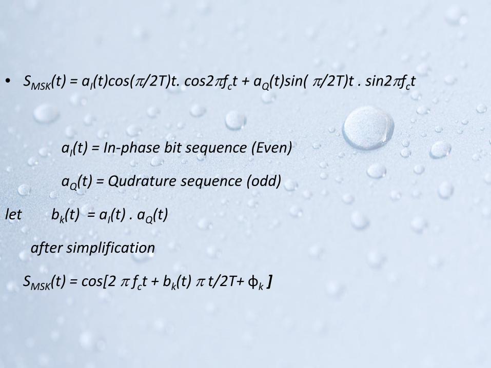
• SMSK(t) = aI(t)cos(π/2T)t. cos2πfct + aQ(t)sin( π/2T)t . sin2πfct
aI(t) = In-phase bit sequence (Even)
aQ(t) = Qudrature sequence (odd)
let bk(t) = aI(t) . aQ(t)
after simplification
SMSK(t) = cos[2 π fct + bk(t) π t/2T+ φk ]

aI(t) & aQ(t) = +1 for Binary “1” & Φk = 0
aI(t) & aQ(t) = -1 for Binary “0” & Φk = π
Also bk(t) = 0 if aI(t) & aQ(t) are opposite
bk(t) = 1 if aI(t) & aQ(t) are same


MSK Receiver

Phasor Diagram

GAUSSIAN MINIMUM SHIFT KEYING
• In GMSK the side lobe levels of the spectrum
are further reduced.
• GMSK will minimize bandwidth, improve
spectral performance, and easy for detection.
• GMSK has excellent power efficiency , so it is
used for GSM applications.
• But GMSK is affected by ISI.

GMSK Transmitter
FM TransmitterGaussian
Filter
Amplifier

• An unfiltered binary data stream will produce
an RF spectrum of considerable bandwidth.
• A Gaussian pulse-shaping filter smoothes the
phase trajectory of input NRZ code.

Gaussian Filter response
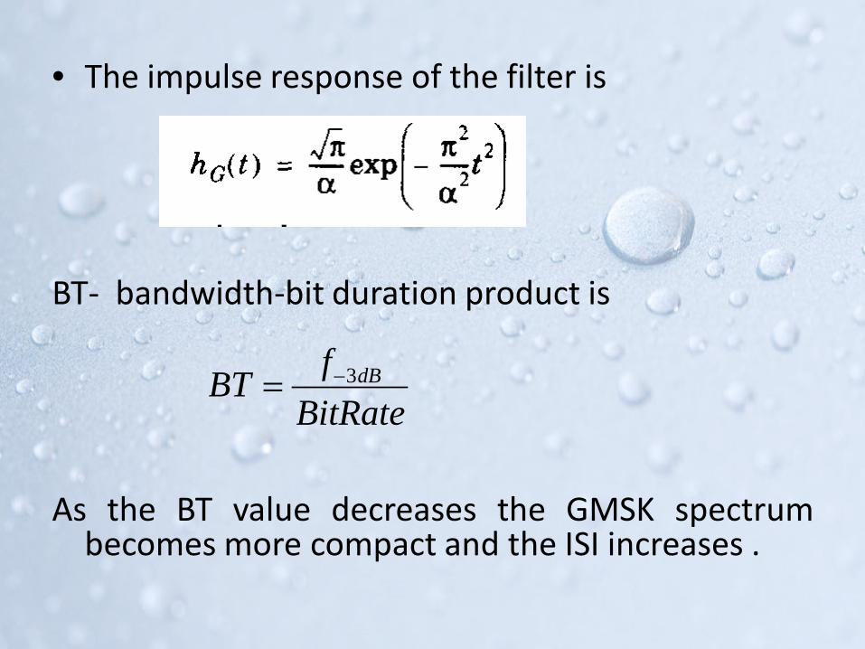
• The impulse response of the filter is
BT- bandwidth-bit duration product is
As the BT value decreases the GMSK spectrumbecomes more compact and the ISI increases .
BitRatefBT dB3−=

– For BT=0.3 the adjacent symbols will interfere with each other more than for BT=0.5

Pulse Shaping
Input NRZ Output from filter

• Input: Binary NRZ Signal
• Each binary pulse goes through a Gaussian LPF
• The filter smoothes the phase trajectory of the binary pulses
and stabilizes the instantaneous frequency variations.
• The power spectrum of MSK & GMSK are equivalent.
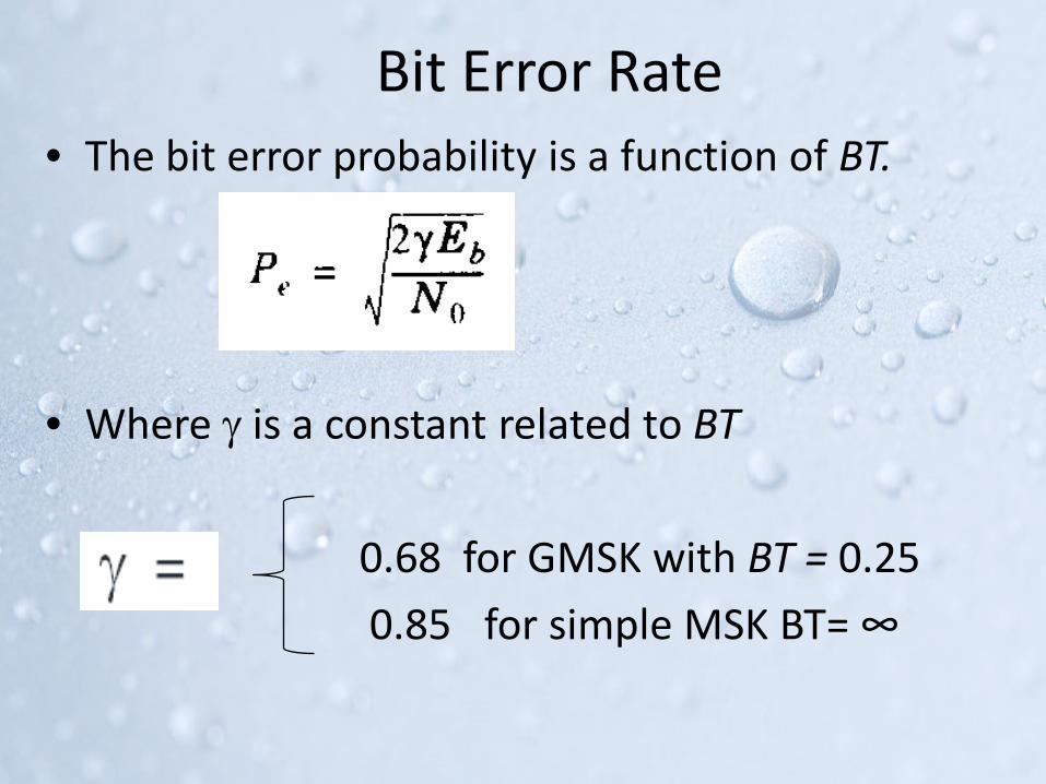
Bit Error Rate• The bit error probability is a function of BT.
• Where γ is a constant related to BT
0.68 for GMSK with BT = 0.25
0.85 for simple MSK BT= ∞
• Eb/N0 is the energy per bit to noise power
spectral density ratio.
• It is a normalized signal-to-noise
ratio (SNR) measure, also known as the
"SNR per bit“
• N0 = Noise Spectral Density

oooooo

MSK Vs GMSK

Receiver