
Wireless Comm (Antenna)
72
WIRELESS COMMUNICATIONS
-
Upload
noreenatis -
Category
Documents
-
view
218 -
download
0
description
yeah
Transcript of Wireless Comm (Antenna)

WIRELESS
COMMUNICATIONS
• Antenna – acts as the interface between a
transmitter or receiver and free space.
Antennas are a very important component of
communication systems.
- it is defined as a device used to transform an
RF signal, traveling on a conductor, into an
electromagnetic wave in free space.
- it can be a length of wire, a metal rod, or a
piece of tubing.
Antenna

the length of the conductor is dependent on
the frequency of operation.
- radiates most effectively when their length
Is directly related to the wavelength of the
transmitted signal.
- it demonstrate a property known as
reciprocity, which means that an antenna
will maintain the same characteristics
regardless if it is transmitting or receiving.

Most antennas are resonant devices, which
operate efficiently over a relatively narrow
frequency band.
Two types of antennas:
1. Transmitting antenna
- radiates the electromagnetic waves.
- converts the electrical energy traveling
along the transmission line into electromagnetic
waves in space.
-
2. Receiving antenna
- intercepts the electromagnetic wave,
- converts the electromagnetic wave into electrical signal down thru a transmission line.
It is analogous to a transmission line designed to radiate or receive energy.
There are parameters to consider:
a. Directivity
b. Gain
c. Input Impedance
d. Polarization
e. Bandwidth
f. Beamwidth

Antennas:
- are called passive devices, since the
power radiated by a transmitting antenna
cannot be greater than the power entering
from the transmitter because of losses due
to cable or transmission loss.
- but it can also be active devices.
in a high communication receiver or an
FM or television broadcast receiver where
the combination of a receiving antenna
with a low noise amplifier.

• Consider a transmission line connected to
a generator or a source of radio-frequency
signals. The generator will send these
radio-frequency signals down the
transmission line toward the load. The
radio or television transmitter can be
considered the generator and the
transmitting antenna as the load.


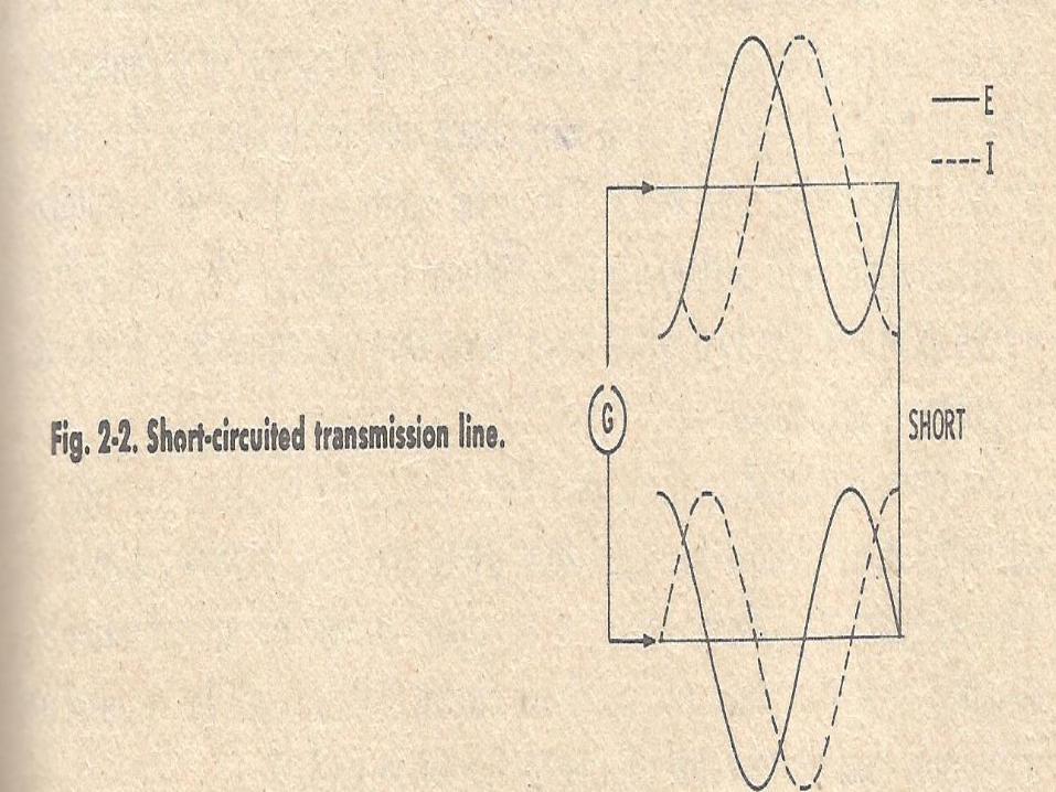
• Transmission line is open:
- the electric field and magnetic field
escape for the end of the line and it will
radiate into space, but, it is inefficient and
unsuitable for reliable xmission or
reception.
- Bending of the transmission line
conductors improved the efficiency of the
radiation and reception.

- Folding the conductors so that they are right
angle to the transmission line will give an
efficient radiation and reception.
- Because magnetic field will no longer cancel but
it will aid one another and the electric filed
spreads out from the conductor, then, it
becomes an ANTENNA.
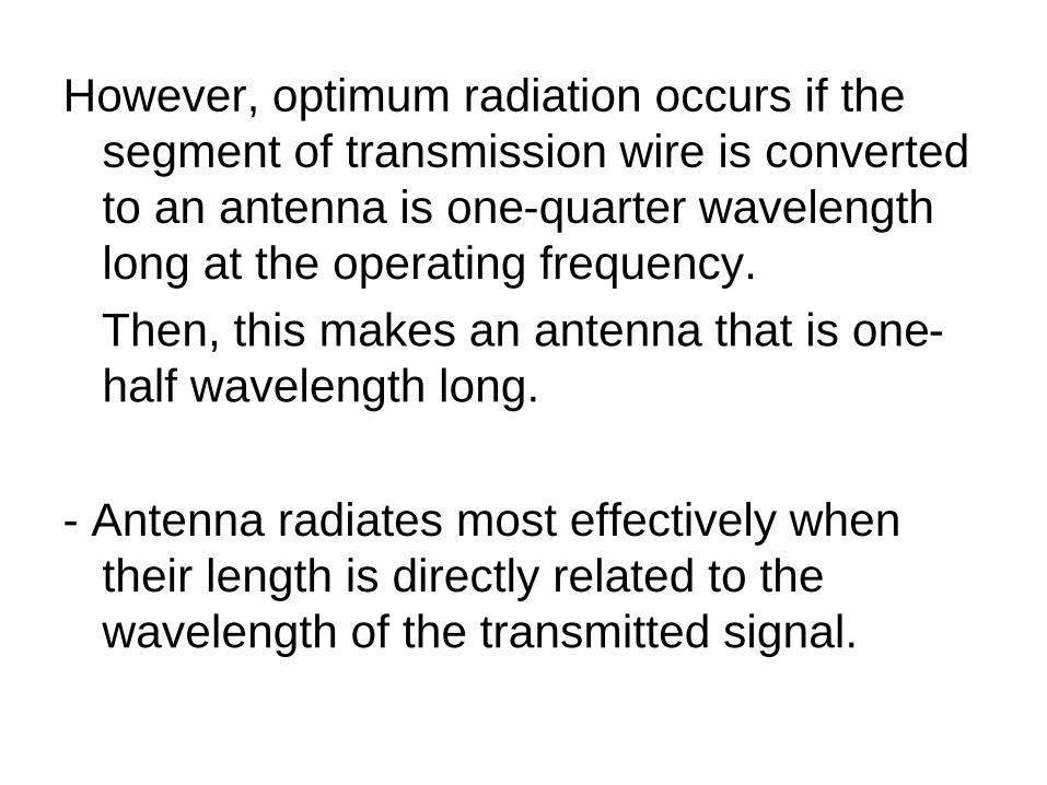
However, optimum radiation occurs if the
segment of transmission wire is converted
to an antenna is one-quarter wavelength
long at the operating frequency.
Then, this makes an antenna that is one-
half wavelength long.
- Antenna radiates most effectively when
their length is directly related to the
wavelength of the transmitted signal.

• The electric field and the magnetic field is
perpendicular with each other and these
two field support each other.
• The ratio of the electric field strength to the
magnetic field strength is a constant and it
is called the Impedance of space or the
wave impedance and it is equal to 377
ohms.
• The resulting fields are radiated into space
at the speed of light.
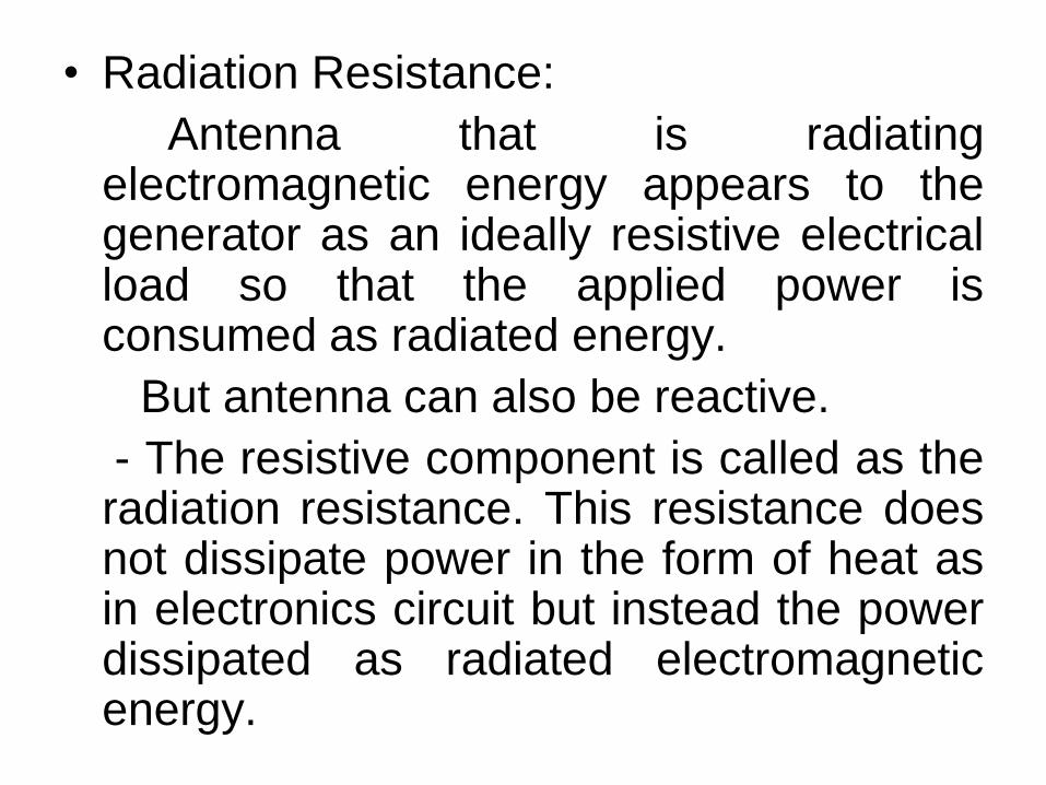
• Radiation Resistance:
Antenna that is radiatingelectromagnetic energy appears to thegenerator as an ideally resistive electricalload so that the applied power isconsumed as radiated energy.
But antenna can also be reactive.
- The resistive component is called as theradiation resistance. This resistance doesnot dissipate power in the form of heat asin electronics circuit but instead the powerdissipated as radiated electromagneticenergy.
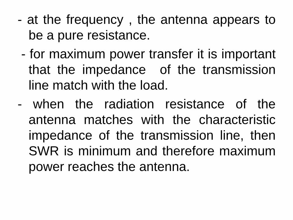
- at the frequency , the antenna appears to
be a pure resistance.
- for maximum power transfer it is important
that the impedance of the transmission
line match with the load.
- when the radiation resistance of the
antenna matches with the characteristic
impedance of the transmission line, then
SWR is minimum and therefore maximum
power reaches the antenna.

SWR – standing wave ratio
- Standing wave occurs when there is
mismatch between the transmission line
an the load.
it is the ratio of the maximum current to the
minimum current, or the maximum voltage
to the minimum voltage, along the line.
SWR = I max / I min, or
= V max / V min

• Since measuring the maximun nd
minimum voltage and current on a line is
not practical in the real world, then SWR is
the ratio of the load impedance to the
characteristic impedance:
SWR = Zl / Zo
Zl = Load impedance
Zo = characteristic impedance

• Antenna produce two sets of fields the
near field and the far field.
Near field – describes as the region
around the antenna where the electric and
magnetic fields are distinct.
- this field weaken with the distance from
the antenna, approximately by quadruple
power of the distance.
- is also referred as the Fresnel Zone.
- rarely used but some application as the
Radio Frequency Identification (RFID).

Far field – which approximately 10
wavelenghts from the antenna is the radio
wave with the composite electric and
magnetic fields.
- it strength also diminishes with the
distance but only at the square of the
distance.
- it is also called as Fraunhofer Zone.
- most wireless application use the far
field wave.

• Input Impedance
For an efficient transfer of energy, the impedance of the radio, of the
antenna and of the transmission cable connecting them must be the same.
- Transceivers and their transmission lines are typically designed for 50Ω
impedance. If the antenna has an impedance different from 50Ω, then
there is a mismatch and an impedance matching circuit is required.

The input impedance of an antenna is defined by
as “the impedance presented by an antenna at
its terminals or the ratio of the voltage to the
current at the pair of terminals or the
ratio of the appropriate components of the
electric to magnetic fields at a point”.
Hence the impedance of the antenna can be
written as:
Zin = Rin + jXin
where :
Zin is the antenna impedance at the terminals
Rin is the antenna resistance at the terminals
Xin is the antenna reactance at the terminals
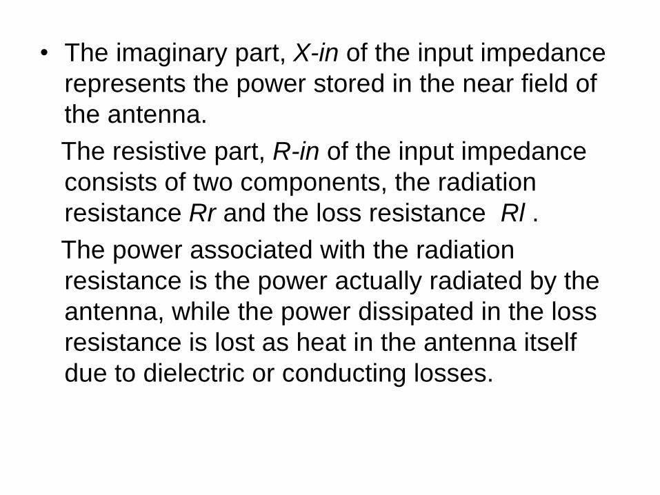
• The imaginary part, X-in of the input impedance
represents the power stored in the near field of
the antenna.
The resistive part, R-in of the input impedance
consists of two components, the radiation
resistance Rr and the loss resistance Rl .
The power associated with the radiation
resistance is the power actually radiated by the
antenna, while the power dissipated in the loss
resistance is lost as heat in the antenna itself
due to dielectric or conducting losses.

• - Return loss
The return loss is another way of expressing
mismatch. It is a logarithmic
ratio measured in dB that compares the
power reflected by the antenna
to the power that is fed into the antenna
from the transmission line.
The relationship between SWR and return
loss is the following:
Return Loss (in dB)
= 20 log 10 SWR/SWR-1
According to their applications and technology
available, antennas generally fall in one of two
categories:
Omnidirectional or only weakly directional
antennas which receive or radiate more or
less in all directions. These are employed
when the relative position of the other station
is unknown or arbitrary. They are also used at
lower frequencies where a directional antenna
would be too large, or simply to cut costs in
applications where a directional antenna isn't
required.

• They are also used at lower frequencies
where a directional antenna would be too
large, or simply to cut costs in applications
where a directional antenna isn't required.
• Directional or beam antennas which are
intended to preferentially radiate or receive
in a particular direction or directional
pattern.
Antenna Characteristics:
Radiation Pattern
-The radiation pattern of an antenna is a
plot of the far-field radiation properties of
an antenna as a function of the spatial co-
ordinates which are specified by the
elevation angle θ and the azimuth angle φ.
-More specifically it is a plot of the power
radiated from an antenna per unit solid
angle which is nothing but the radiation
intensity .

Main Lobe: This is the radiation lobe containing
the direction of maximum radiation.
Minor Lobe: All the lobes other then the main
lobe are called the minor lobes.
These lobes represent the radiation in undesired
directions. The level of minor lobes is usually
expressed as a ratio of the power density in the
lobe in question to that of the major lobe. This
ratio is called as the side lobe level (expressed
in decibels).

Back Lobe: This is the minor lobe diametrically opposite the main lobe.
Side Lobes:
- These are the minor lobes adjacent to the main lobe and are separated by various nulls.
- are generally the largest among the minor lobes.
-No antenna is able to radiate all the energy in one preferred direction.
- Some is inevitably radiated in other directions. The peaks are referred to as sidelobes, commonly specified in dB down from the main lobe.

- Nulls
In an antenna radiation pattern, a null is a
zone in which the effective radiated power
is at a minimum. A null often has a narrow
directivity angle
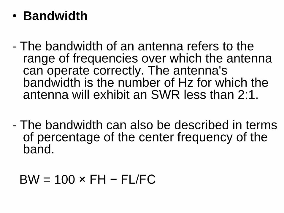
• Bandwidth
- The bandwidth of an antenna refers to the range of frequencies over which the antenna can operate correctly. The antenna's bandwidth is the number of Hz for which the antenna will exhibit an SWR less than 2:1.
- The bandwidth can also be described in terms of percentage of the center frequency of the band.
BW = 100 × FH − FL/FC
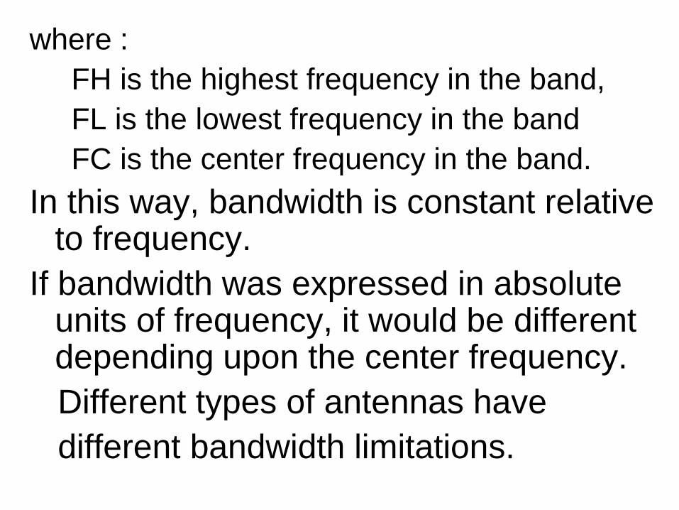
where :
FH is the highest frequency in the band,
FL is the lowest frequency in the band
FC is the center frequency in the band.
In this way, bandwidth is constant relative to frequency.
If bandwidth was expressed in absolute units of frequency, it would be different depending upon the center frequency.
Different types of antennas have
different bandwidth limitations.

- Directivity
is the ability of an antenna to focus energy in a particular direction when transmitting, or to receive energy better from a particular direction when receiving.
- In a static situation, it is possible to use the
antenna directivity to concentrate the radiation beam in the wanted direction. However in a dynamic system where the transceiver is not
fixed, the antenna should radiate equally in all directions, and this is known as an omni-directional antenna.

The relationship of the gain with respect to
Directivity:
Gain is the directivity multiplied by the
efficiency of the antenna:
G = Dn
where:
G = Gain, as ratio (not in dB)
D = Directivity
n = efficiency

where :
n = Pr / Pt
n= antenna efficiency
Pr= radiated power
Pt= power supplied to the antenna

Gain
is a parameter which measures the degree
of directivity of the antenna's radiation
pattern. A high-gain antenna will
preferentially radiate in a particular
direction.
it is defined as the output over the input
dB = 10 log P out / P in

• Specifically, the antenna gain, or power
gain of an antenna is defined as the ratio
of the intensity (power per unit surface)
radiated by the antenna in the direction of
its maximum output, at an arbitrary
distance, divided by the intensity radiated
at the same distance by a hypothetical
isotropic antenna.
• High-gain antennas have the advantage of
longer range and better signal quality, but
must be aimed carefully in a particular
direction.
• Low-gain antennas have shorter range,
but the orientation of the antenna is
relatively inconsequential.

- Beamwidth
The angular distance between the half power
points is defined as the beamwidth.
An antenna's beamwidth is usually
understood to mean the half-power
beamwidth.
The peak radiation intensity is found and then
the points on either side of the peak which
represent half the power of the peak intensity
are located.

- Half the power expressed in decibels is 3dB,
so the half power beamwidth is sometimes
referred to as the 3dB beamwidth.
Both horizontal and vertical beamwidths
are usually considered.
Assuming that most of the radiated power is
not divided into sidelobes, then the
directive gain is inversely proportional to
the beamwidth: as the beamwidth
decreases, the directive gain increases.
- Beamwidth – measure’s the antenna
directivity.
therefore, the narrower the beamwidth,
the better the directivity and more highly
focused the signal becomes.
• Let us consider the case of an isotropic
antenna.
An isotropic antenna is one which radiates
equally in all directions.
If the total power radiated by the isotropic
antenna is P , then the power is spread
over a sphere of radius r ,so that the
power density S at this distance in any
direction is given as:

HPBW: The half power beamwidth (HPBW) can
be defined as the angle subtended by the half
power points of the main lobe.
• Front to Back Ratio
- the direction of maximum radiation in the
horizontal plane is considered to be the front
of the antenna, and the back is the direction
180 deg. from the front.
- for a dipole, front and back ratio have the
same direction 180 deg. from the front.
• POLARIZATION
- The electric field determines the direction of polarization of the wave.
The most common types of polarization
include:
a. linear (horizontal or vertical) and
b. circular (right hand polarization or the left hand polarization).
In a vertically polarized wave, the electric lines of force lie in a vertical direction.
-In a horizontally polarized wave, the electric lines of force lie in a horizontal direction.
-

Circular polarization has the electric lines of
force rotating through 360 degrees with
every cycle of rf energy.
In a circularly polarized wave, the electric
field vector remains constant in length but
rotates around in a circular path. A left
hand circular polarized wave is one in
which the wave rotates counterclockwise
whereas right hand circular polarized wave
exhibits clockwise motion as shown in
Figure.
- In a vertically polarized wave, the electric
lines of force lie in a vertical direction.
-In a horizontally polarized wave, the
electric lines of force lie in a horizontal
direction.

• The electric field was chosen as the reference
field because the intensity of the wave is usually
measured in terms of the electric field intensity
(volts, millivolts, or microvolts per meter).
• When a single-wire antenna is used to extract
energy from a passing radio wave, maximum
pickup will result when the antenna is oriented in
the same direction as the electric field.
• Thus a vertical antenna is used for the efficient
reception of vertically polarized waves, and a
horizontal antenna is used for the reception of
horizontally polarized waves.

• In some cases the orientation of the
electric field does not remain constant
• Instead, the field rotates as the wave
travels through space. Under these
conditions both horizontal and vertical
components of the field exist and the wave
is said to have an elliptical polarization.

• IMPEDANCE MATCHING:
- One of the most critical aspects of any
antenna system is to ensure maximum
power transfer from the transmitter to the
antenna.
- when the SWR is equal to 1:1, maximum
power transfer will take place.
- then, characteristic impedance of the
transmission line matches the output
impedance of the transmitter and the
impedance of the antenna itself.
To prevent mismatch between the antenna
and transmission line is through correct
design.
When mismatches occur, some corrections
are possible:
1. Tune the antenna by adjusting its length
to minimize SWR.
2. Insert impedance-matching circuit or
antenna tuner between the transmitter and
the transmission line.

Impedance matching circuits:
1. Balun or LC
2. L
3. T
4. pie
The ideal is an SWR of 1, but any SWR
value below 2 is usuallu acceptable.

Basic antenna models.
ISOTROPIC RADIATOR:
- is a purely theoretical antenna that radiates all the electrical power supplied to it and equally distribute in all directions.
- it is considered to be a point in space with no dimensions and no mass.
-This antenna cannot physically exist, but is useful as a theoretical model for comparison with all other antennas.

Most antennas' gains are measured with reference to an isotropic radiator, and are rated in dBi (decibels with respect to an isotropic radiator)
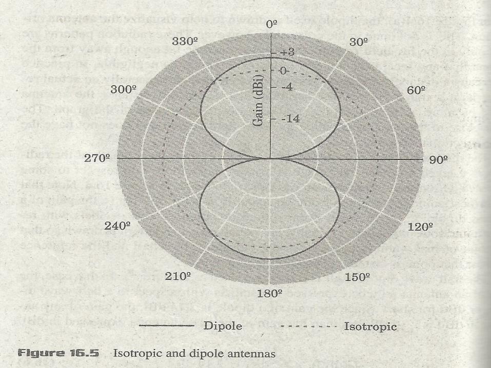
Dipole antenna:
is simply two wires pointed in opposite
directions arranged either horizontally or
vertically, with one end of each wire connected
to the radio and the other end hanging free in
space.

Dipole – means it has two parts
- it does not mean that dipole is always one-half
wavelength in length but we allow it for
impedance matching.
Since this is the simplest practical antenna, it
is also used as a reference model for other
antennas; gain with respect to a dipole is
labeled as dBd.
NOTE: 0 dBd = 2.15 dBi. It is vital in
expressing gain values that the reference point
be included. Failure to do so can lead to
confusion and error.

The directive gain of a half wave dipole is
known to be 1.64 & it can be made nearly
100% efficient. Since gain has been
measured with respect to this reference
antenna.
GdBd = 10 log G/1.64
G(dBd)= G(dBi) -2.15 dB
Where: G(dBd) =gain of antenna in decibels
with respect to a half-wave dipole.
G(dBi) = gain of the antenna in
decibels with respect to an isotropic
radiator.

Generally, the dipole is considered to be
omnidirectional in the plane perpendicular
to the axis of the antenna, but it has deep
nulls in the directions of the axis.
Variations of the dipole include the folded
dipole, the half wave antenna, the ground
plane antenna, the whip, and the J-pole.


Yagi-Uda antenna
is a directional variation of the dipole with
parasitic elements added which are
functionality similar to adding a reflector
and lenses (directors) to focus a filament
light bulb.
Random wire antenna
is simply a very long (at least one quarter
wavelength) wire with one end connected
to the radio and the other in free space,
arranged in any way most convenient for
the space available.

Folding will reduce effectiveness and
make theoretical analysis extremely
difficult. (The added length helps more
than the folding typically hurts.) Typically,
a random wire antenna will also require an
antenna tuner, as it might have a random
impedance that varies non-linearly with
frequency.
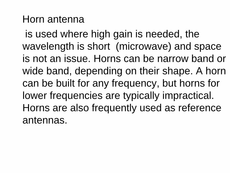
Horn antenna
is used where high gain is needed, the
wavelength is short (microwave) and space
is not an issue. Horns can be narrow band or
wide band, depending on their shape. A horn
can be built for any frequency, but horns for
lower frequencies are typically impractical.
Horns are also frequently used as reference
antennas.
Parabolic antenna
- consists of an active element at the focus of a
parabolic reflector to reflect the waves into a
plane wave. Like the horn it is used for high
gain, microwave applications, such as satellite
dishes.
Patch antenna
- consists mainly of a square conductor mounted
over a groundplane. Another example of a
planar antenna is the tapered slot antenna
(TSA), as the Vidaldi-antenna.

Yagi-Uda beam antenna
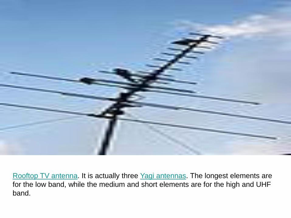
Rooftop TV antenna. It is actually three Yagi antennas. The longest elements are
for the low band, while the medium and short elements are for the high and UHF
band.

Examples of US 136-174 MHz base station antennas.