Wireless Charging of a Supercapacitor Model Vehicle Using...
9
WIRELESS CHARGING OF A SUPERCAPACITOR MODEL VEHICLE USING MAGNETIC RESONANCE COUPLING Minfan Fu, Tong Zhang, Chengbin Ma ∗ , Xinen Zhu Univ. of Michigan-Shanghai Jiao Tong Univ. Joint Institute Shanghai Jiao Tong University, No. 800 Dongchuan Road, Shanghai 200240, P. R. China Email: [email protected] ABSTRACT This paper discusses the basic considerations and develop- ment of a prototype demo system for the wireless charging of supercapacitor electric vehicles, which uses magnetic resonance coupling. Considering future ubiquitous wireless vehicle station- ary and dynamic charging facilities, supercapacitor could be an ideal device to store a reasonable amount of electrical energy for a relatively short period of time. The prototype system in- cludes all the major functional components for an electric ve- hicle’s powertrain and wireless charging system including coils for energy emitting and receiving, a FPGA PWM input genera- tion board, high frequency DC/AC inverter and AC/DC rectifier circuits, an on-board supercapacitor module, sensors for SOC level measurement and charging position detection, etc. All the components are integrated into a model electric vehicle. The prototype system well demonstrates the idea of the fast and fre- quent wireless charging of on-board supercapacitors. Promising results from initial experiments are explained; while further in- vestigations, optimized design of components and a system-level optimization are needed. 1 Introduction It has been world-widely recognized that electrifying vehi- cles can provide a solution to the emission and oil shortage prob- lems brought by billions of conventional vehicles today, which are propelled by internal combustion engines. Consequently the most current research on electric vehicles (including the hybrid electric vehicles) are focusing on their environment and energy aspects. And one of the key issues for widespread use on elec- tric vehicles is considered to largely rely on the development of long-term energy storage devices with competitive cost. However, the specific energy of petrol (12000Wh/kg) is hun- dreds of times that of a mass-market battery (20∼200Wh/kg) [1]. A high battery storage capacity and more efficient electric motor are not enough to entirely compensate for the huge mismatch in energy density. Depending on existing battery technology alone is unlikely to make electric vehicles competitive against conven- tional internal combustion engine vehicles. Innovative ideas are needed to take full advantage of the vehicle electrification. This will require a new generation of vehicles specifically designed and configured as electric vehicles, not the conventional vehicles converted to electric ones by simply replacing engine and tank with electric motor and battery pack. Compared with chemical and mechanical energy, electrical energy is easier and more efficient to transform, transfer and con- trol. It is said that the future of electric vehicles is relying on the breakthrough of the battery technology, which means the fu- ture vehicles will continue to depend on the chemical energy, but only move from oil-dependent to battery-dependent. However, the energy density, reliability, life cycle and management of bat- teries are always problematic. Considering the urgent global- scale challenges of environment and energy shortage problems, obviously besides waiting for a substantial progress in battery technology, other alternative technological options are also de- sired. And it is crucial to take full advantage of the revolutionary impacts brought by the electrification of vehicles. The idea of wireless transfer of electrical energy has been 1 Copyright © 2013 by ASME Proceedings of the ASME 2013 International Design Engineering Technical Conferences and Computers and Information in Engineering Conference IDETC/CIE 2013 August 4-7, 2013, Portland, Oregon, USA DETC2013-12530 Downloaded From: http://proceedings.asmedigitalcollection.asme.org/ on 06/09/2014 Terms of Use: http://asme.org/terms
Transcript of Wireless Charging of a Supercapacitor Model Vehicle Using...
WIRELESS CHARGING OF A SUPERCAPACITOR MODEL VEHICLE USINGMAGNETIC RESONANCE COUPLING
Minfan Fu, Tong Zhang, Chengbin Ma∗, Xinen ZhuUniv. of Michigan-Shanghai Jiao Tong Univ. Joint Institute
Shanghai Jiao Tong University, No. 800 Dongchuan Road, Shanghai 200240, P. R. ChinaEmail: [email protected]
ABSTRACTThis paper discusses the basic considerations and develop-
ment of a prototype demo system for the wireless charging ofsupercapacitor electric vehicles, which uses magnetic resonancecoupling. Considering future ubiquitous wireless vehicle station-ary and dynamic charging facilities, supercapacitor could be anideal device to store a reasonable amount of electrical energyfor a relatively short period of time. The prototype system in-cludes all the major functional components for an electric ve-hicle’s powertrain and wireless charging system including coilsfor energy emitting and receiving, a FPGA PWM input genera-tion board, high frequency DC/AC inverter and AC/DC rectifiercircuits, an on-board supercapacitor module, sensors for SOClevel measurement and charging position detection, etc. All thecomponents are integrated into a model electric vehicle. Theprototype system well demonstrates the idea of the fast and fre-quent wireless charging of on-board supercapacitors. Promisingresults from initial experiments are explained; while further in-vestigations, optimized design of components and a system-leveloptimization are needed.
1 IntroductionIt has been world-widely recognized that electrifying vehi-
cles can provide a solution to the emission and oil shortage prob-lems brought by billions of conventional vehicles today, whichare propelled by internal combustion engines. Consequently themost current research on electric vehicles (including the hybridelectric vehicles) are focusing on their environment and energy
aspects. And one of the key issues for widespread use on elec-tric vehicles is considered to largely rely on the development oflong-term energy storage devices with competitive cost.
However, the specific energy of petrol (12000Wh/kg) is hun-dreds of times that of a mass-market battery (20∼200Wh/kg) [1].A high battery storage capacity and more efficient electric motorare not enough to entirely compensate for the huge mismatch inenergy density. Depending on existing battery technology aloneis unlikely to make electric vehicles competitive against conven-tional internal combustion engine vehicles. Innovative ideas areneeded to take full advantage of the vehicle electrification. Thiswill require a new generation of vehicles specifically designedand configured as electric vehicles, not the conventional vehiclesconverted to electric ones by simply replacing engine and tankwith electric motor and battery pack.
Compared with chemical and mechanical energy, electricalenergy is easier and more efficient to transform, transfer and con-trol. It is said that the future of electric vehicles is relying onthe breakthrough of the battery technology, which means the fu-ture vehicles will continue to depend on the chemical energy, butonly move from oil-dependent to battery-dependent. However,the energy density, reliability, life cycle and management of bat-teries are always problematic. Considering the urgent global-scale challenges of environment and energy shortage problems,obviously besides waiting for a substantial progress in batterytechnology, other alternative technological options are also de-sired. And it is crucial to take full advantage of the revolutionaryimpacts brought by the electrification of vehicles.
The idea of wireless transfer of electrical energy has been
1 Copyright © 2013 by ASME
Proceedings of the ASME 2013 International Design Engineering Technical Conferences and Computers and Information in Engineering Conference
IDETC/CIE 2013 August 4-7, 2013, Portland, Oregon, USA
DETC2013-12530
Downloaded From: http://proceedings.asmedigitalcollection.asme.org/ on 06/09/2014 Terms of Use: http://asme.org/terms
known from long time ago. Nikola Tesla proposed a “world sys-tem” for “the transmission of electrical energy without wires”that applies capacitive coupling in 1904 [2]. In recent years, thereis a renewed interest in the research and applications of wirelessenergy transfer. Various methods have been applied such as in-ductive coupling, magnetic resonance coupling, microwave andlaser radiation, etc [3]- [10]. Instead of near field in both induc-tive coupling and magnetic resonance coupling, microwave andlaser radiation use far field to transfer electric power wirelessly.Efforts are needed to design a proper antenna array to shape theradiation beam correctly to ensure a high efficiency power trans-mission. A focused beam usually requires a large size antennaarray. Besides, high power microwave/laser power sources areexpensive.
The magnetic resonance coupling occurs when powersources and receiving devices are specially designed magneticresonators with approximately same natural frequencies [6]. Theinductive coupling systems can also be tuned to resonance [5][11]. As another near-field method, inductive coupling is a ma-ture technique that is widely used today for both low and highpower applications. It can enable large power transfer in the or-der of tens of kW with a 10cm air gap between emitting coiland receiving coil at a low 90’s% overall system efficiency [12].The power transfer distance for inductive coupling technique hasbeen improved to 20 cm with the optimization of the magneticstructure [13]. The inductive coupling systems usually operatein kHz band because the state-of-art power electronic devicesare available for both power generation and conditioning. Onthe other hand, this low frequency requires a large size coil andheavy ferrite materials, which may not be favored by vehiclesin terms of payload efficiency. The weight of an on-board re-ceiving coil with its ferrite core may be over 35kg for a 30kWcommercial inductive coupling system [12]. The magnetic reso-nance coupling systems work at higher operating frequencies inMHz band. It is considered to be promising for the purpose ofthe wireless vehicle charging due to the following advantages:
1. High efficiency at moderate distance2. Large transmission distance with moderate efficiency3. Only interact with resonant body (lower electromagnetic ex-
posure to non-resonant body)4. Lighter weight (no need of iron or ferrite cores)5. More compact in size
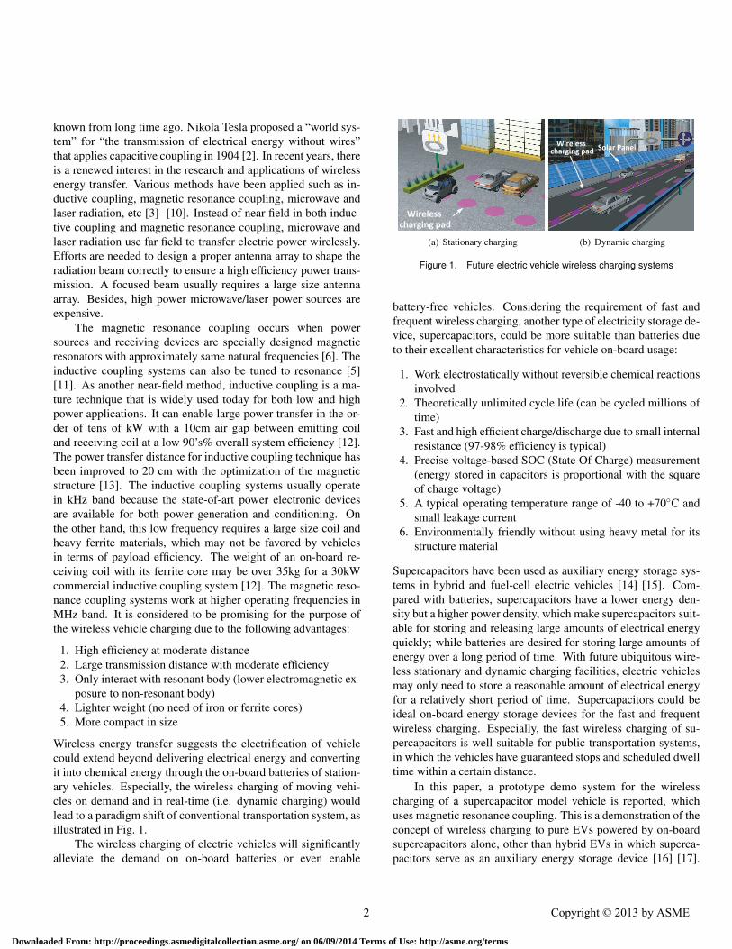
Wireless energy transfer suggests the electrification of vehiclecould extend beyond delivering electrical energy and convertingit into chemical energy through the on-board batteries of station-ary vehicles. Especially, the wireless charging of moving vehi-cles on demand and in real-time (i.e. dynamic charging) wouldlead to a paradigm shift of conventional transportation system, asillustrated in Fig. 1.
The wireless charging of electric vehicles will significantlyalleviate the demand on on-board batteries or even enable
Wireless
charging pad
(a) Stationary charging
Wirelesscharging pad
Solar Panel
(b) Dynamic charging
Figure 1. Future electric vehicle wireless charging systems
battery-free vehicles. Considering the requirement of fast andfrequent wireless charging, another type of electricity storage de-vice, supercapacitors, could be more suitable than batteries dueto their excellent characteristics for vehicle on-board usage:
1. Work electrostatically without reversible chemical reactionsinvolved
2. Theoretically unlimited cycle life (can be cycled millions oftime)
3. Fast and high efficient charge/discharge due to small internalresistance (97-98% efficiency is typical)
4. Precise voltage-based SOC (State Of Charge) measurement(energy stored in capacitors is proportional with the squareof charge voltage)
5. A typical operating temperature range of -40 to +70C andsmall leakage current
6. Environmentally friendly without using heavy metal for itsstructure material
Supercapacitors have been used as auxiliary energy storage sys-tems in hybrid and fuel-cell electric vehicles [14] [15]. Com-pared with batteries, supercapacitors have a lower energy den-sity but a higher power density, which make supercapacitors suit-able for storing and releasing large amounts of electrical energyquickly; while batteries are desired for storing large amounts ofenergy over a long period of time. With future ubiquitous wire-less stationary and dynamic charging facilities, electric vehiclesmay only need to store a reasonable amount of electrical energyfor a relatively short period of time. Supercapacitors could beideal on-board energy storage devices for the fast and frequentwireless charging. Especially, the fast wireless charging of su-percapacitors is well suitable for public transportation systems,in which the vehicles have guaranteed stops and scheduled dwelltime within a certain distance.
In this paper, a prototype demo system for the wirelesscharging of a supercapacitor model vehicle is reported, whichuses magnetic resonance coupling. This is a demonstration of theconcept of wireless charging to pure EVs powered by on-boardsupercapacitors alone, other than hybrid EVs in which superca-pacitors serve as an auxiliary energy storage device [16] [17].
2 Copyright © 2013 by ASME
Downloaded From: http://proceedings.asmedigitalcollection.asme.org/ on 06/09/2014 Terms of Use: http://asme.org/terms

With the maturity of wireless charging technique, future EVscan be even powered by the electrical power wirelessly with aminimum loading of battery/supercapacitor. The prototype sys-tem includes coils for energy emitting and receiving, a FPGA(Field-Programmable Gate Array) PWM (Pulse Width Modu-lation) input generation board, high frequency DC/AC inverterand AC/DC rectifier circuits, an on-board supercapacitor mod-ule, sensors for SOC level measurement and charging positiondetection, and a model electric vehicle. Namely, all the majorfunctional components for an electric vehicle’s powertrain andcharging system are included. Promising results from the initialexperiments are also explained; while further investigations, op-timized design of components and a system-level optimizationare needed.
The operating frequency for the magnetic resonance cou-pling spans from kHz to GHz [18]. Higher frequency is usuallydesired for more compact and lighter resonators. However, thereare restrictions on the usable frequency range under the regu-lation of ISM (industrial, scientific and medical) band and theperformances of power switching devices [19]. For a validationpurpose, in the prototype system the DC/AC resonant inverter iscomposed of four high speed MOSFETs with targeted frequencyof 1MHz for the generated AC power.
2 Wireless Charging System Design2.1 Coils
As shown in Fig. 2, there are three types of coils in the wire-less charging system, namely one emitting coil, two resonatingcoils, and one receiving coil, respectively. The resonating coilswork as an isolated transformer to transfer the electromagneticenergy from one winding to another using magnetic resonancecoupling which is intended to extend the transfer distance to aconsiderable level, such as 10cm; while the conventional mag-netic coupling without resonance can only reach a transfer dis-tance less than 1cm without sacrificing the transfer efficiency.The emitting and receiving coils are non-resonating coils. Theyare inductively coupled to the resonating coils as the input/outputterminal in order to minimize the effect of external loading to theresonating coils, which usually decreases the quality factor ofeach resonating coil, thus the transfer efficiency.
To achieve the maximum power transfer efficiency ofthis coil combination, the distance between the transmit-ting/receiving coil and its adjacent resonating coil need to be op-timized as well as the distance between two resonating coils. Atthe same time, the receiving coil presents an inductance to therectifier and charging circuit. This inductance makes the charg-ing circuit behave as a current source that is actually required bythe charging characteristics of supercapacitors.
The operating frequency of 1 MHz is selected as an initialtarget for the wireless charging system. At this frequency, theresonating coils can be modeled as a parallel LC resonant circuit.
High
frequency
rectifier
+
supercapacit-
or module
Transfer
distance
Emitting system Receiving system
Emitting
coil
Resonating
coils
Receiving
coil
High
frequency
resonant
inverter
Figure 2. The configuration of the wireless energy transfer system
The resonance frequency is determined by the inductance andcapacitance using Equ. (1),
f =1
2π√
LC= 1MHz. (1)
Namely,
LC = 2.533×10⁻¹⁴H ·F. (2)
The circular shape coils are used to achieve the required induc-tance due to the simple structure and accurate theoretical induc-tance calculation. The inductance of a circular coils is calculatedby Equ. (3),
Lcircle = N2Rµ0µr
[ln(
8Ra
)−2
]. (3)
where N is the number of turns, R the radius of the circular coil,a wire radius, µ0 absolute permeability (4π×10−7H/m), and µrrelative permeability of the medium (i.e. the ratio of the mate-rial’s permeability to the permeability in air) which is 1 sincemagnetic resonance coupling does not need core. The radius ofthe selected wire is 0.7mm and the radius of the circular coil isapproximately 10cm. The N is 5. Then the inductance is around15.8µH and the capacitance is calculated to be 1.6nF.
2.2 High-frequency Resonant InverterIn the emitting system, a high-frequency DC/AC inverter is
designed to supply the AC power at the resonance frequencyof the two resonating coils. A full bridge voltage-fed topol-ogy is applied to perform the high-frequency DC/AC inversion.The schematic and photograph of the voltage-fed resonant in-verter are shown in Fig. 3(a) and (b), respectively. The fourgates are high-speed semiconductor MOSFET switches, InfineonIPD30N10S3L MOSFETs. The time characteristics of the MOS-FET is shown in Tbl. 1. Parallel soft switching capacitors areemployed to charge/discharge during the dead time; therefore,
3 Copyright © 2013 by ASME
Downloaded From: http://proceedings.asmedigitalcollection.asme.org/ on 06/09/2014 Terms of Use: http://asme.org/terms

the switching losses can be essentially eliminated and also thestresses on the MOSFET switches are alleviated. As mentionedabove, 1MHz is selected as the targeted frequency of the ACpower converted by the full bridge resonant inverter.
Table 1. Time Characteristics of MOSFET
Turn-on delay time td(on) 6ns
Rise time tr 4ns
Turn-off delay time td(o f f ) 18ns
Fall time t f 3ns
(a) Schematic circuit diagram
(b) Photograph
Figure 3. The high-frequency voltage-fed resonant inverter
The two half-bridges are driven by two MOSFET driver ICs,Texas Instruments UCC27201, respectively, which control thehigh side and low side MOSFET gates with PWM inputs. AFPGA board, Digilent Nexys2 built around a Xilinx Spartan-3EFPGA, is programmed by Verilog to generate a 1MHz square
wave PWM input signals with MOSFET switching dead timeconsidered.
2.3 Receiving systemThe receiving system consists of resonating coil, receiving
coil, AC/DC rectifier and supercapacitors to receive and storagethe electromagnetic energy being wirelessly transferred from theemitting system. The resonating coil is as same as the resonatingcoil adjacent to the emitting coil. The 1MHz alternating electro-magnetic energy is picked up by the resonating coil through mag-netic resonance coupling; while the energy is then transferred tothe receiving coil by inductive coupling. As shown in Fig. 4, thetwo coils are concentric and lie in the same plane to maximizethe power transfer efficiency.
Resonating coil Receiving coil
Super-
capacitors and
RectifierVoltage
indicator
Figure 4. The wirelessly charged supercapacitor model vehicle
The whole receiving system is integrated with a rear two-wheel drive model electric vehicle. Especially, ten FalacapJLPA2R7106 supercapacitors instead of batteries are used aselectricity storage devices for the fast and frequent wirelesscharging. Each supercapacitor has a rated 10F capacitance and2.7V voltage, as shown in Tbl. 2. The supercapacitors are con-nected by 2P5S, i.e. 2 capacitors are in parallel and 5 in series;therefore the total rated capacitance and voltage are 10× 2/5 =4F and 2.7×5 = 13.5V, respectively (see Fig. 5). A LED voltageindicator is introduced to visualize the SOC level of the superca-pacitor module because the electrical energy stored in a capacitoris proportional with the square of its charge voltage.
Zetex ZHCS2000 surface mount Schottky Barrier Diode ischosen as the full bridge rectifier circuit diode, as shown inFig. 5(b). The diode has very fast reverse recovery time trr of5.5ns and small typical reverse current IR of 160µA, which aresuitable for high frequency rectification. The DC output of therectifier is connected to the supercapacitor module. As shown inFig. 6, the model vehicle has a similar configuration as real full-size electric vehicles. It can be used as a platform to investigateand verify the fast and frequency wireless charging of superca-pacitor electric vehicles, the interactive relationship among var-ious components from wireless energy transfer, storage to con-
4 Copyright © 2013 by ASME
Downloaded From: http://proceedings.asmedigitalcollection.asme.org/ on 06/09/2014 Terms of Use: http://asme.org/terms

Table 2. Specifications of supercapacitor
Rated capacitance 10F
Rated voltage DC 2.7V
Internal resistance (AC) < 30mΩ
Internal resistance (DC) < 50mΩ
Maximum current >9.00A
Size (D×L) 12mm(Φ) × 26mm(H)
Weight 3.0g
Power density 3.38Wh/kg / 4.30Wh/L
(a) Supercapacitor module
(b) Schematic circuit diagram of rectifier and superca-pacitors
Figure 5. Supercapacitor module and high frequency rectifier
sumption, and the optimized configuration, design and controlstrategy, etc.
3 Prototype Demo System ConfigurationThe entire wireless charging system for the supercapacitor
model vehicle is shown in Fig. 7. The prototype system in-cludes all the major functional components for an electric ve-hicle’s powertrain and wireless charging system including emit-ting coil, two resonating coils, 1MHz PWM input signal gener-ation FPGA board, high frequency resonant inverter, receiving
Rectifier
Resonating
Coil
Receiving
Coil
AC
(1MHz) DCSupercapacitor
module
DC
Trace
moduleMotor control unit
Trajectory
signal
Supercapacitor
voltage signal
Control
signal
LED array
Voltage
levelPower flow
Signal flow
Left
motor
Right
motor
Motor
drive
board
Figure 6. The configuration of the supercapacitor model vehicle
coil, high frequency rectifier, supercapacitor electricity storagedevice, motor control unit (MCU), motor driver and electric mo-tors.
Emitting coil
Resonating coil
1MHz PWM input
signal generation
FPGA board
High frequency
resonant inverter
Resonating coil
Receiving coil Vehicle track
High frequency
rectifier
Supercapacitor
module
(a) Prototype demo system
Charging position
detector MCU and drive
board
Electric
motors
Supercapacitor
voltage (SOC)
indicator
Tracking sensors
(b) Model vehicle and sensors
Figure 7. The prototype demo system configuration
As mentioned in the above section, the voltage-fed resonantinverter generates 1MHz PWM output voltage under the switch-ing command from the FPGA board; one resonating coil next tothe emitting coil picks up the alternating electromagnetic energyfrom emitting coil by inductive coupling; while another resonat-ing coil receives the energy from resonating coil through mag-netic resonance coupling and again the energy is transferred to
5 Copyright © 2013 by ASME
Downloaded From: http://proceedings.asmedigitalcollection.asme.org/ on 06/09/2014 Terms of Use: http://asme.org/terms

receiving coil, which is inductively coupled with its adjacent res-onating coil; then the 1MHz AC power is converted to DC powerfor the charging of supercapacitor module.
Special attention is also paid to the communication amongvehicle, wireless charging station and road conditions includingthe sensing of SOC level of on-board electricity storage device,the position of wireless charging station and vehicle track, asshown in Fig. 7(b). The model vehicle tracks the black trajec-tory and automatically returns to the charging area when the SOC(voltage) level of the supercapacitor module is lower than a pre-scribed reference value. The charging system can communicatewith the model vehicle and start the wireless charging when themodel vehicle stops at the charging area due to the low SOClevel.
4 Initial Experimental ResultsCurrent initial experimental results of the wireless charging
prototype system are reported as follows, while further detailedinvestigations are still needed. The simple experimental setup isshown in Fig. 8, in which the DC-link voltage for resonant in-verter is 10V. Firstly the 1MHz resonant frequency is confirmedby measuring the voltage and current in the emitting coil, asshown in Fig. 9. It is observed that while the voltage in emit-ting coil is in square wave, a sine wave current is observed in thecoil, which is expected from a voltage inverter in the design.
DC link power
supply
Multimeters for voltage andcurrent measurement
Supercapacitor module
+Rectifier
Resonant Inverter
Emitting coil
Resonating coil
Resonating coil
FPGA boardMOSFET driver IC
power supply
Receiving coil
Figure 8. The experimental setup
Network analyzer is used to figure out the frequency char-acteristics among emitting coil, resonating coils and receivingcoil. The network analyze has two ports, one is for inputtinghigh frequency signals and the other is used to read the cor-responding transmitted signals. Fig. 10 is obtained using net-work analyzer with 10cm distance between the two resonatingcoils. The figure clearly shows the maximum energy transfer ef-ficiency occurs at frequency of 995kHz, which is in accordance
Voltage
Current
1usec
Figure 9. The voltage and current waves in the emitting coil
with the design target. The magnitude ratio is -1.42dB. Namely,20log10(Vout/Vin) = −1.42, where Vin and Vout are the magni-tudes of input and output voltages. Therefore, the energy trans-fer efficiency is (Vout/Vin)
2 = 72.1%. Fig. 11 and Tbl. 3 showthe relationship between various resonant coil distance and cor-responding energy transfer efficiency. Currently, the 50% effi-ciency occurs at the distance of about 22cm.
-1.42 dB at
995kHz
Figure 10. Transmission characterization of coils by network analyzer
Fig. 12(a)(b) show the voltage and current responses of thesupercapacitor module and the DC power supply respectivelyduring a complete wireless charging cycle, when the distancebetween the two resonating coils is 8cm. The total charging du-ration is approximately three minutes, which is much faster thanthat of Li-ion batteries as expected. The DC power supply main-tains a constant voltage of 10V, while the current increases from0.5 to 1A during the charging cycle. Therefore, the power pro-vided by the DC supply power changes from 5 to 10W. For the
6 Copyright © 2013 by ASME
Downloaded From: http://proceedings.asmedigitalcollection.asme.org/ on 06/09/2014 Terms of Use: http://asme.org/terms

5 10 15 20 25 30 35 40 45 500
10
20
30
40
50
60
70
80
90
100
Distance (cm)
Ene
rgy
Tra
nsfe
r E
ffici
ency
(%
)
Figure 11. Resonant coil distance versus energy transfer efficiency
Table 3. Experimental Data for Distance Versus Efficiency
Distance (cm) Magnitude Ratio (dB) Efficiency (%)
5 -0.38 91.6
6 -0.44 90.4
7 -0.61 86.9
8 -0.72 84.7
9 -0.96 80.2
10 -1.42 72.1
15 -1.949 63.8
20 -2.737 53.2
25 -3.786 41.8
30 -4.671 34.1
35 -6.425 22.8
40 -7.618 17.3
45 -10.05 9.9
50 -11.809 6.6
supercapacitor module, the current almost stays constant witha slight decrease over the charging cycle while the voltage in-creases monotonically from 0.78 to 12.37V. This observation isconsistent with the constant current charging characteristic of su-percapacitors. The power transfer to the supercapacitor modulesvaries from 0.36 to 3.87W. The total system efficiency is cal-culated and plotted in Fig. 13, in which the maximum systemefficiency is approximately 38%.
0 20 40 60 80 100 120 140 160 1800
1
2
3
4
5
6
7
8
9
10
11
12
13
14
15
Time (sec)
Cha
rge
volta
ge (
V)
0 20 40 60 80 100 120 140 160 1800
0.1
0.2
0.3
0.4
0.5
0.6
0.7
0.8
0.9
1
1.1
1.2
1.3
1.4
1.5
Cha
rge
curr
ent (
A)
VoltageCurrent
(a) Supercapacitor modules
0 20 40 60 80 100 120 140 160 1800
1
2
3
4
5
6
7
8
9
10
11
12
13
14
15
Time (sec)
DC
pow
ersu
pply
vol
tage
(V
)
0 20 40 60 80 100 120 140 160 1800
0.1
0.2
0.3
0.4
0.5
0.6
0.7
0.8
0.9
1
1.1
1.2
1.3
1.4
1.5
DC
pow
er s
uppl
y cu
rren
t (A
)
VoltageCurrent
(b) DC power supply
Figure 12. Supercapacitor wireless charging characteristics
0 20 40 60 80 100 120 140 160 1800
5
10
15
20
25
30
35
40
45
50
Time (sec)
Effi
cien
cy (
%)
Figure 13. Total system efficiency
5 Conclusions and Future WorksThe design and configuration of a prototype vehicle wireless
charging system are reviewed in detail including the winding andparameter tuning of coils, high frequency AC/DC and DC/ACconversion circuits, integration with the supercapacitor module,the model electric vehicle and sensors, etc. The prototype sys-tem well demonstrates the idea of the fast and frequent wirelesscharging of supercapacitor electric vehicles using magnetic res-
7 Copyright © 2013 by ASME
Downloaded From: http://proceedings.asmedigitalcollection.asme.org/ on 06/09/2014 Terms of Use: http://asme.org/terms
onance coupling. Though wireless energy transfer is consideredto be complicated, it is proved to be a handy technology from thework described above. However, both component and system-level optimization are very challenging. Intensive investigationsand research are expected in the future.
With this functional prototype system, several future workscan be conducted. The costs of different power supply systemswill be evaluated, such as wirelessly charged supercapacitors andLi-ion batteries. The corresponding control strategy will also bedeveloped. It is interesting to demonstrate the dynamic wire-less charging of the supercapacitor model vehicle. And the opti-mized design of circuits and coils are important for improvingthe efficiencies of energy transfer and transformation. Mean-while, the system-level optimization of a wireless charging sys-tem need real-time feedback from the energy receiving/storagedevice, road and power sources through sophisticated sensorsand wireless communication. A control strategy for such opti-mization will be an essential issue. The mini prototype systemcan work as a convenient testing platform to practice many novelideas on the wireless charging of electric vehicles.
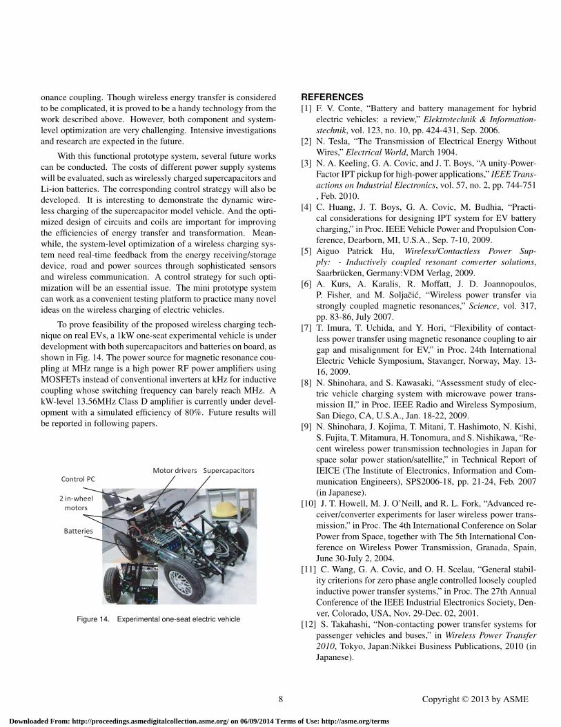
To prove feasibility of the proposed wireless charging tech-nique on real EVs, a 1kW one-seat experimental vehicle is underdevelopment with both supercapacitors and batteries on board, asshown in Fig. 14. The power source for magnetic resonance cou-pling at MHz range is a high power RF power amplifiers usingMOSFETs instead of conventional inverters at kHz for inductivecoupling whose switching frequency can barely reach MHz. AkW-level 13.56MHz Class D amplifier is currently under devel-opment with a simulated efficiency of 80%. Future results willbe reported in following papers.
Control PC
Supercapacitors
2 in-wheel
motors
Batteries
Motor drivers
Figure 14. Experimental one-seat electric vehicle
REFERENCES[1] F. V. Conte, “Battery and battery management for hybrid
electric vehicles: a review,” Elektrotechnik & Information-stechnik, vol. 123, no. 10, pp. 424-431, Sep. 2006.
[2] N. Tesla, “The Transmission of Electrical Energy WithoutWires,” Electrical World, March 1904.
[3] N. A. Keeling, G. A. Covic, and J. T. Boys, “A unity-Power-Factor IPT pickup for high-power applications,” IEEE Trans-actions on Industrial Electronics, vol. 57, no. 2, pp. 744-751, Feb. 2010.
[4] C. Huang, J. T. Boys, G. A. Covic, M. Budhia, “Practi-cal considerations for designing IPT system for EV batterycharging,” in Proc. IEEE Vehicle Power and Propulsion Con-ference, Dearborn, MI, U.S.A., Sep. 7-10, 2009.
[5] Aiguo Patrick Hu, Wireless/Contactless Power Sup-ply: - Inductively coupled resonant converter solutions,Saarbrucken, Germany:VDM Verlag, 2009.
[6] A. Kurs, A. Karalis, R. Moffatt, J. D. Joannopoulos,P. Fisher, and M. Soljacic, “Wireless power transfer viastrongly coupled magnetic resonances,” Science, vol. 317,pp. 83-86, July 2007.
[7] T. Imura, T. Uchida, and Y. Hori, “Flexibility of contact-less power transfer using magnetic resonance coupling to airgap and misalignment for EV,” in Proc. 24th InternationalElectric Vehicle Symposium, Stavanger, Norway, May. 13-16, 2009.
[8] N. Shinohara, and S. Kawasaki, “Assessment study of elec-tric vehicle charging system with microwave power trans-mission II,” in Proc. IEEE Radio and Wireless Symposium,San Diego, CA, U.S.A., Jan. 18-22, 2009.
[9] N. Shinohara, J. Kojima, T. Mitani, T. Hashimoto, N. Kishi,S. Fujita, T. Mitamura, H. Tonomura, and S. Nishikawa, “Re-cent wireless power transmission technologies in Japan forspace solar power station/satellite,” in Technical Report ofIEICE (The Institute of Electronics, Information and Com-munication Engineers), SPS2006-18, pp. 21-24, Feb. 2007(in Japanese).
[10] J. T. Howell, M. J. O’Neill, and R. L. Fork, “Advanced re-ceiver/converter experiments for laser wireless power trans-mission,” in Proc. The 4th International Conference on SolarPower from Space, together with The 5th International Con-ference on Wireless Power Transmission, Granada, Spain,June 30-July 2, 2004.
[11] C. Wang, G. A. Covic, and O. H. Scelau, “General stabil-ity criterions for zero phase angle controlled loosely coupledinductive power transfer systems,” in Proc. The 27th AnnualConference of the IEEE Industrial Electronics Society, Den-ver, Colorado, USA, Nov. 29-Dec. 02, 2001.
[12] S. Takahashi, “Non-contacting power transfer systems forpassenger vehicles and buses,” in Wireless Power Transfer2010, Tokyo, Japan:Nikkei Business Publications, 2010 (inJapanese).
8 Copyright © 2013 by ASME
Downloaded From: http://proceedings.asmedigitalcollection.asme.org/ on 06/09/2014 Terms of Use: http://asme.org/terms

[13] M. Budhia, G. Covic and J. Boys, “Design and Optimiza-tion of Circular Magnetic Structures for Lumped InductivePower Transfer Systems,” The inaugural IEEE Energy Con-version Conference and Exposition, ECCE 2009, San JoseCalifornia, United States, Sept. 20-24., 2009, pp. 2081-2088.
[14] M. Ortuzar, J. Moreno, and J. Dixon, “Ultracapacitor-basedauxiliary energy system for an electric vehicle: Implementa-tion and Evaluation,” IEEE Transactions on Industrial Elec-tronics, vol. 54, no. 4, pp. 2147-2156, Aug. 2007.
[15] P. Thounthong, S. Rael, and B. Davat, “Control strategyof fuel cell and supercapacitors association for a distributedgeneration system,” IEEE Transactions on Industrial Elec-tronics, vol. 54, no. 6, pp. 3225-3233, Dec. 2007.
[16] Haerri V.V. Madawala U.K., Thrimawithana D.J., ArnoldR. and Maksimovic A. “A Plug in Hybrid Blue Angel III forvehicle to grid system with a wireless grid interface” in IEEEVPPC conference, pp. 1-5, 2010.
[17] Haerri V.V. and Martinovic D. “Supercapacitor ModuleSAM for Hybrid Busses: an Advanced Energy Storage Spec-ification based on Experiences with the TOHYCO-RiderBus Project in IEEE IES 33rd annual conference IECON,pp. 268-273, 2007.
[18] T. Imura, H. Okabe, T. Koyanagi, M. Kato, T. C. Beh, M.Ote, J. Shimamoto, M. Takamiya, and Y. Hori, “Proposalof wireless power transfer via magnetic resonant couplingin kHz-MHz-GHz,” in Proc. general conference 2010 IE-ICE (The Institute of Electronics, Information and Commu-nication Engineers), Sendai, Japan, March 16-19, 2010 (inJapanese).
[19] “Improving the effectiveness, flexibility and availability ofspectrum for short range devices,” in Document RAG07-1/17-E, Radiocommunication Advisory Group, InternationalTelecommunication Union, Jan. 2007.
9 Copyright © 2013 by ASME
Downloaded From: http://proceedings.asmedigitalcollection.asme.org/ on 06/09/2014 Terms of Use: http://asme.org/terms