Wireless Broadcast Using Network Coding
27
Wireless Broadcast Using Network Coding Speaker: Yu-Jen Lai Cheng-Chih Chao Advisor: Hung-Yu Wei 2009/06/08 1 Dong Nguyen, Tuan Tran, Thinh Nguyen, and Bella Bose, Fellow, IEEE IEEE TRANSACTIONS ON VEHICULAR TECHNOLOGY, FEBRUARY 2009
description
IEEE TRANSACTIONS ON VEHICULAR TECHNOLOGY, FEBRUARY 2009. Speaker: Yu-Jen Lai Cheng-Chih Chao Advisor: Hung-Yu Wei. Wireless Broadcast Using Network Coding. Dong Nguyen, Tuan Tran, Thinh Nguyen, and Bella Bose, Fellow, IEEE. Outline. Introduction – Network Coding - PowerPoint PPT Presentation
Transcript of Wireless Broadcast Using Network Coding

Wireless Broadcast Using Network Coding
Speaker: Yu-Jen Lai Cheng-Chih Chao Advisor: Hung-Yu Wei
2009/06/08 1
Dong Nguyen, Tuan Tran, Thinh Nguyen, and Bella Bose, Fellow, IEEE
IEEE TRANSACTIONS ON VEHICULAR TECHNOLOGY, FEBRUARY 2009
Outline
Introduction – Network CodingBroadcast SchemesPerformance AnalysisSimulation ResultConclusion
2009/06/08 2

Reliable Broadcast
How to transmit data reliably?
Traditional approaches:1.Automatic repeat-request (ARQ)2.Forward error correction (FEC)
2009/06/08 3

NC in wireless ad hoc networks
R1 can recover b as a+(a+b)R2 can recover a as b+(a+b)
2009/06/08 4

NC in broadcast scheme
We can use Network Coding for both increase reliability and throughput
2009/06/08 5

Broadcast SchemesScheme A (Memoryless Receiver)
The sender has to resend a packet until all the receivers receive this packet correctly and simultaneously
Scheme B (Typical ARQ Scheme) Receiver immediately sends a NAK only
if there is a packet loss in the current time slot
2009/06/08 6

Broadcast Schemes (cont.)Scheme C (Time-Based
Retransmission) Transmission phase and retransmission
phase The sender maintains a list of lost
packets In the retransmission phase, xoring a
maximum set of the lost packet to retransmit
Scheme D (Improved Time-Based Retransmission) Dynamically change the combined
packets based on what the receivers have received
2009/06/08 7
Scheme C Scheme D

Performance analysis Transmission bandwidth
The average number of transmissions required to successfully transmit a packet
Calculate BW of schemes A, B, C, D.
Let pi denote the packet loss probability of receiver i.
2009/06/08 8

Performance analysis (Scheme A and B)
Scheme A and B (2 receivers)
M receivers

Performance analysis (Scheme A and B)
Proof (2 receivers) Let X1 and X2 be the numbers of
attempts to deliver a packet to R1 and R2

Performance analysis (Scheme A and B)
Proof (M receivers)

Performance analysis (Scheme C)
Scheme C (2 receivers)
Proof N: buffer size, assume p1<p2

Performance analysis (Scheme C)
Scheme C (M receivers)
Proof

Performance analysis (Scheme D)
Scheme D (M receivers)
Proof In the long run, the number of losses will be
dominated by the number of losses at the receiver with the largest error probability

Performance analysis (cont.)Calculate network coding gain
Compare the BW of C and D with B

Simulation result
Simulation categoriesA. Packet losses independent,
uncorrelated across the receiversB. Packet losses independent, correlated
across the receiversC. Burst losses (using two-state Markov
chain)

Simulation result (1) Transmission bandwidths of schemes A,
B, C, D, under 2 receivers and p2=0.1, p1 varies The number of transmissions per successful
packet in scheme D is the smallest, which is slightly more efficient than scheme C.

Simulation result (2) Network coding gain V.S. different p1
The gain is largest when p1 and p2 is equal. Because in this case, the maximum number of lost packet pairs is achieved.
On the other hand, when two receivers have disparate packet loss rates, the coding gain is small

Simulation result (3) Transmission bandwidth versus the
number of receivers Scheme C and D significantly outperform
scheme A and B when the number of receivers is large
Scheme C increases very slightly ; Scheme D is unchange (Theorem 3)

Simulation result (4) Network coding gain V.S. packet loss
probability in a 5-receiver scenario The packet loss probabilities at other receivers
are: p2=p3=0, p4=p1+0.3, p5=0.3 Even if some receiver without a packet loss,
network coding scheme is still better.
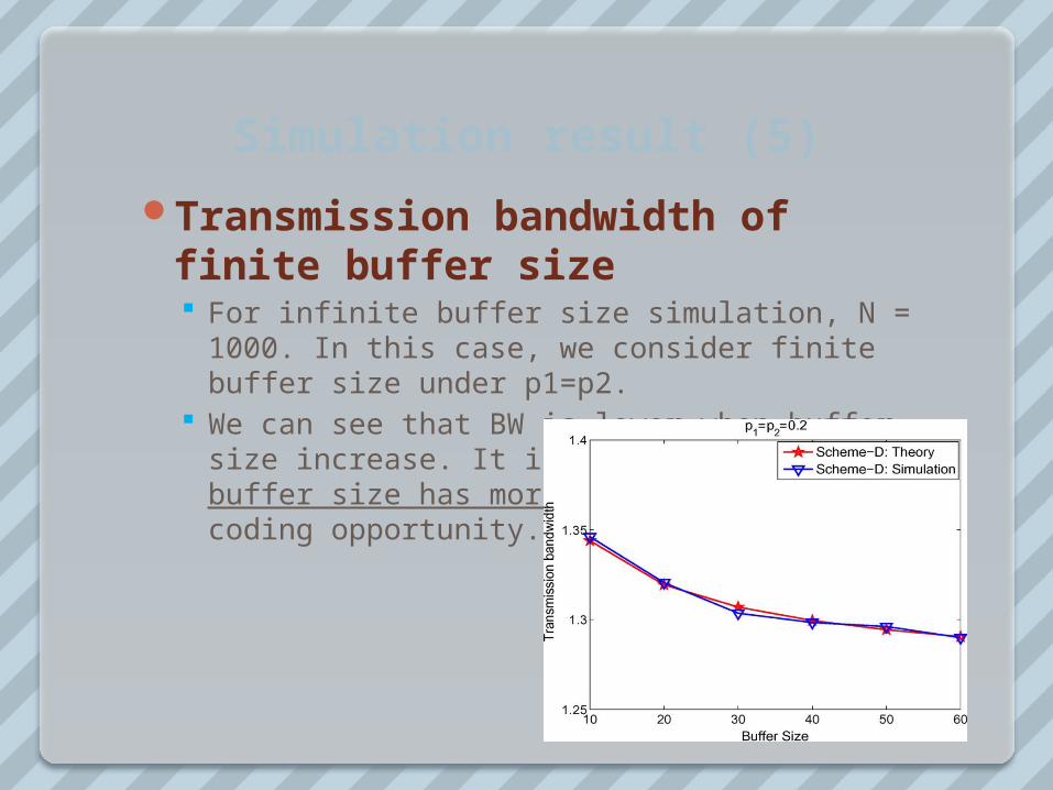
Simulation result (5)
Transmission bandwidth of finite buffer size For infinite buffer size simulation, N = 1000. In
this case, we consider finite buffer size under p1=p2.
We can see that BW is lower when buffer size increase. It is because that larger buffer size has more coding pair and more coding opportunity.

Simulation result (6)
Categories B: Correlate packet loss

Simulation result (7)
Correlate packet loss (conditional prob.)
More correlated, less loss pair to code

Simulation result (8)
Categories C: Two-state Markov chain Two channel state: “bad” and “good” α=pgood→bad ; β=pbad→good

Conclusion Advantage
The idea of using network coding is good (scheme C). (In scheme D) It also concern that retransmission packet may be
loss only at part of receivers. The analysis procedure is simple and result is concise (closed-form).
Drawback Some condition can be improved
The full knowledge of which packet loss by which receiver The price of using network coding is that packet need to be
decoded in receiver (but this price is small compared with the network coding gain)
Simulation is too many simplification(ex. no contention, no higher layer considered)
As the buffer increase, the latency may also increase (not suitable for multimedia applications)
It will break down if there is no feedback channel Full of ACK in this system since it assume BS knows everything;
besides, there is a big problem that broadcast ACK may contention severely
2009/06/08 25

Thanks for listening!!
2009/06/08 26

Backup: Hamming CodeHamming (7,4) code:
2009/06/08 27