Wire Wool Failure of a Compressor Rotor
20
Wire Wool Failure of a Compressor Rotor 38 th Turbomachinery Symposium Case Study Presented By: Bryan Barrington Machinery Engineer LyondellBasell Specialty Engineering Group Keith Burnikell Reliability Engineer LyondellBasell Bayport Facility
Transcript of Wire Wool Failure of a Compressor Rotor

Wire Wool Failure of a Compressor Rotor
38th Turbomachinery Symposium Case Study
Presented By:
Bryan BarringtonMachinery Engineer
LyondellBasell Specialty Engineering Group
Keith BurnikellReliability Engineer
LyondellBasell Bayport Facility

Machine Characteristics
• Double flow beam type centrifugal compressor driven by an electric motor on one end and a steam turbine on the other
• 13,390 HP• 8676 rpm• 15-5 PH shaft material with low carbon
manganese steel overlay in bearing journal areas
Presenter
Presentation Notes
Shaft surface speed is XXX 15-5 PH is required due to water and carbon dioxide in gas stream

T ; lll;
·.. , ... _.LT u.. ..
___ l_j I 0
LJ

4. 56 (REF ) ---~-e----.......
LENGTH OF OVERLAY
Area of Failure~ ------- 1
J!
---+--+- - ---f-1-
. 25 CREF)

Timeline of Events
• Machine restarted after complete overhaul and oil system flush
• Cooling water to oil cooler not lined up –oil supply to deck approaches 170 F
• Cooling water reinstated but vibration tracks oil supply temperature swings –swings caused by fouled cooler
• One cooler taken off-line to clean water (tube) side – bundle pulled
Presenter
Presentation Notes
Mention Morton Effect relationship as well as 3rd critical operation

Timeline of Events (cont’d)
• Bundle reinstalled and cooler placed back on line
• Approximately 6 minutes later the journal bearing temperature began to increase
• Three minutes later the vibration dipped and then began a rapid increase
• Machine tripped out by board operator – 9 mils vibration recorded on Bently system
Presenter
Presentation Notes
Mention Morton Effect relationship as well as 3rd critical operation

Cleaned cooler placed on line
Lube Oil Supply Temperature (F)
Journal Bearing Temperature (F)
Comp Vibration (mils)
Presenter
Presentation Notes
Oil temp change 2:44 pm Brg Temp Increase 2:51 pm Vib min 2:54 pm Vib max 3:01 pm

• With machine disassembled it was readily apparent that it had experienced a wire wool failure.
• Debris from machining appeared as wire wool.
– Pre-disassembly• Shaft runout approaching 25 mils TIR• Spiral windings in oil drain line bull’s eye


Wire Wool Background
• Mechanism driven by:– Steels containing chromium in excess of 1-1.5%
• 15-5 PH / 17-4 PH• 400 series stainless
– Shaft speeds in excess of 67-80 feet/sec– Foreign particle (soft or hard)– References / Further Reading
• API RP 687 Rotor Repair, First Edition p 1-157• Metallurgical Considerations in Wire Wool Type Wear
Bearing Phenomena, F. Fidler, 1970

Wire Wool Background (cont’d)
• Typical Failure Sequence– Foreign particle introduced into tight clearance– Frictional heat generated due to particle rub at high
speed– Chromium in the steel in the presence of a
hydrocarbon oil is converted to hard chromium carbide
– Chromium carbide particles embed in stationary component and act as a cutting tool
– The mechanism self-propagates until something gives

Additional Findings
• Other bearing journals exhibited scoring
• Oil filter housing contained significant amount of large debris
• Oil pump suction screen mesh much tighter than large debris

• •
•
•
•
• •

Additional Findings
• Debris originated from:– Lube oil supply high temperature swings
performed additional “cleaning”?• Oil temperature excursion to 170 F• Sudden oil temperature drop when cooler placed
on line– Contaminated oil cooler bundle?
• Would require passage through filterReference Dynamic Filter Efficiency
– Combination of above?
Presenter
Presentation Notes
A downstream source of trash could be due to “fluffing” the filters. Hy-Pro Filter Corporation refers to this as “Dynamic Filter Efficiency”. They basically describe this as a filter releasing some of its trash due to things such as flow swings, temperature changes, viscosity changes, etc. We inspected the oil filters. There was quite a bit of trash upstream of the filters. Some of it was highly oxidized chunks. We checked the suction strainer of the pump that was in service and did not find a means for bypassing. Its fine mesh screen was intact and had some fine particles in it (consistency of sand).

Additional Findings
• Oil seal– Split design incorporated due to coupling on
thrust bearing end– Spare thrust bearing oil seal had offsets at
splitline– Existing oil seal design could lock up thus
further forcing any trash against shaft

Note radial offset here
Spare Oil Seal – Example of Design and Manufacturing Flaws
And axial offset here

Modifications – Oil Seal
• Match marked halves• Add dowels to splitline to improve alignment
capability. • Add anti-rotation slot to the lower half holder.
This ensures that the anti-rotation pin does not accidentally get hung in the existing hole in the upper half. Plugged hole in upper half.
• Axial clearance changed to .005 to .010” (old design clearance was .002” to .005”).
• Seal captured by bolted cover vs. relying on thrust bearing
Presenter
Presentation Notes
Thrust bearing allowed one seal to have minimum clearance and opposite seal to have excessive clearance. Seal material - 6061T6 Aluminum

Repairs – Previous Service Shaft
• Shaft of previous service rotor coated to eliminate high chrome at surface– Tungsten carbide coating, minimum thickness
of .005” per side, but for this repair it was approximately .015” per side
– Surface finish was made the same as the surrounding metal at a value of 18 Ra.
– The coating is a JP-5000 coating.
Presenter
Presentation Notes
Mention that the nut that the opposite thrust bearing oil seal runs against is not 15-5 PH.
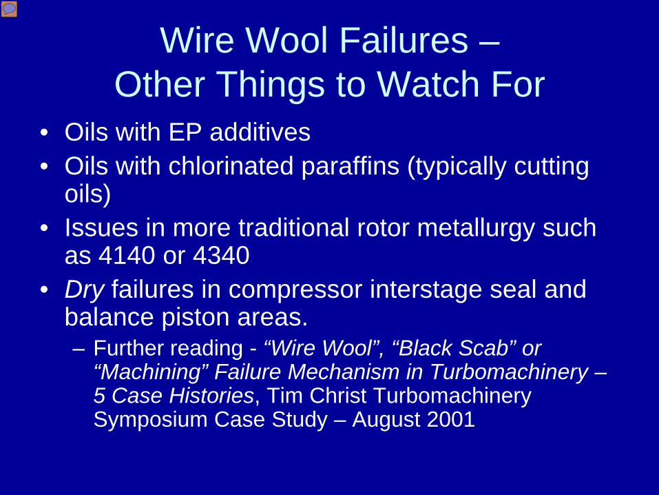
Wire Wool Failures –Other Things to Watch For
• Oils with EP additives• Oils with chlorinated paraffins (typically cutting
oils)• Issues in more traditional rotor metallurgy such
as 4140 or 4340• Dry failures in compressor interstage seal and
balance piston areas.– Further reading - “Wire Wool”, “Black Scab” or
“Machining” Failure Mechanism in Turbomachinery –5 Case Histories, Tim Christ Turbomachinery Symposium Case Study – August 2001
Presenter
Presentation Notes
Principle low alloy steels[4] SAE designationComposition 13xxMn 1.75% 40xxMo 0.20% or 0.25% or 0.25% Mo & 0.042% S 41xxCr 0.50% or 0.80% or 0.95%, Mo 0.12% or 0.20% or 0.25% or 0.30% 43xxNi 1.82%, Cr 0.50% to 0.80%, Mo 0.25% 44xxMo 0.40% or 0.52% 46xxNi 0.85% or 1.82%, Mo 0.20% or 0.25% 47xxNi 1.05%, Cr 0.45%, Mo 0.20% or 0.35% 48xxNi 3.50%, Mo 0.25% 50xxCr 0.27% or 0.40% or 0.50% or 0.65% 50xxxCr 0.50%, C 1.00% min 50BxxCr 0.28% or 0.50% 51xxCr 0.80% or 0.87% or 0.92% or 1.00% or 1.05% 51xxxCr 1.02%, C 1.00% min 51BxxCr 0.80% 52xxxCr 1.45%, C 1.00% min 61xxCr 0.60% or 0.80% or 0.95%, V 0.10% or 0.15% min 86xxNi 0.55%, Cr 0.50%, Mo 0.20% 87xxNi 0.55%, Cr 0.50%, Mo 0.25% 88xxNi 0.55%, Cr 0.50%, Mo 0.35% 92xxSi 1.40% or 2.00%, Mn 0.65% or 0.82% or 0.85%, Cr 0.00% or 0.65% 94BxxNi 0.45%, Cr 0.40%, Mo 0.12%

Lessons Learned
• Historical success does not mean that design improvements do not exist
• Hindsight truly is 20/20• Cleanliness is paramount when exposing
the oil side of coolers to atmosphere• Swapping from dirty to clean coolers
should be performed smoothly to minimize temperature and viscosity swings