Wire Rope Technical Manual - Bridon- · PDF fileFactory and sales Av. Marechal Rondon, 1215...
62
Wire Rope Technical Manual Choose quality
-
Upload
trankhuong -
Category
Documents
-
view
216 -
download
1
Transcript of Wire Rope Technical Manual - Bridon- · PDF fileFactory and sales Av. Marechal Rondon, 1215...

Wire Rope Technical Manual
Choose quality

Factory and sales
Av. Marechal Rondon, 1215ZIP Code 06093-900 - Osasco - SP
Phone: 0800 709 3777Fax: (0xx11) 2147-8555
www.cimaf.com.br
April 2013
Technical Manual
Wire Rope
Choose quality
54
Presentation
The wire ropes presented in this catalogue are manufactured with raw material provided by Belgo Bekaert Arames, a joint venture between ArcelorMittal – world reference in the steel industry and Bekaert – world reference in the manufacture of wires.
The Cimaf® rope was the first wire rope manufactured in Brazil and consolidated itself as the one of greater volume in Latin America. The Cimaf® line of wire rope is the most complete one in the continent.
Their products became renowned as a symbol of quality and trust, full technical support being a differential of the brand.
Its manufacture counts with the most modern technology, following the highest standards of quality.
What was good became even better.
The Cimaf® wire ropes integrate the Belgo Bekaert Arames line of products, with all its technology acquired on the course of years of research. Belgo Bekaert Arames offers a line products which is increasingly complete and with an excellent level of quality, ensuring the achievement of designs with technological growth and evolution.
To use Cimaf® wire ropes is an assurance of safety with protection of the greatest asset: LIFE.
Quality Assurance
Cimaf maintains a dynamic Quality Assurance System, in continuous enhancement, seeking product constant improvement, through the essential element which is man.
This system is detailed in the Quality Manual and defines the inspection plans which accompany the entire production, from the raw matter until the product. This process certified by the ISO 9001:2008, by the American Petroleum Institute (API) and by the Instituto Nacional de Metrologia [National Metrology Institute], includes gauging and calibrating all the metering instruments and tests, including the internals audits of the system, according to the national and international rules and standards.
1 Wires 9
1.1 Quality in material ...........................................................................9
2 Wire ropes 13
2.1 Constructions and lay types ..........................................................132.1.1 Number of strands and number of wires in each strand ......................132.1.2 Core type .........................................................................................162.1.3 Direction and Lay Type ......................................................................17
2.2 Rope lay length .............................................................................182.3 Lubrification ..............................................................................182.4 Preforming ...................................................................................202.5 Wire rope strength ........................................................................212.6 How to make an order ..................................................................22
3 Properties of the wire rope 23
3.1 Working loads limit and design factors ..........................................233.2 Constructional Stretch of the wire ropes ........................................243.3 Diameter of a wire rope .................................................................26
4 Recommendations for using 27
4.1 Choice of construction as a function of the application ..................274.2 Diameters of sheaves and drums ..................................................274.3 Fleet angle ....................................................................................29
5 Handling 31
5.1 How to handle ..............................................................................315.2 Winding in smooth drum or reel ....................................................33
6 Wire rope splicing 35
76
9.7 Wire rope class 6x19 - Steel core .................................................619.8 Wire rope class 6x36 - Fibre core..................................................629.9 Wire rope class 6x36 - Steel core .................................................639.10 CWire rope class 6x36 - Steel core ...............................................649.11 Wire rope class 8x19 - Fibre core Special for Passenger Elevators - Traction .....................................659.12 Cabo de aço classe 8x19 - Alma de fibra Especial para Elevadores de Passageiros - Limitador .....................659.13 Wire rope class 18x7 ....................................................................669.14 Wire rope class 6x19 - Fibre Core - Fishing ...................................679.15 ProPac .........................................................................................689.16 PowerPac .....................................................................................699.17 ErgoFlex .......................................................................................709.18 ErgoFlex Plus ................................................................................719.19 MinePac .......................................................................................72
10 Recommendations of wire ropes 74
10.1 Bulldozer ......................................................................................7410.2 Bulldozer ......................................................................................7510.3 Bulldozer ......................................................................................7610.4 Crane on tracks ............................................................................7710.5 Stationary crane ...........................................................................7810.6 Overhead crane ............................................................................7910.7 Suction dredge .............................................................................8010.8 Transportation of wooden logs ......................................................8110.9 Pile driver .....................................................................................8210.10 Mining - Inclined plane ..................................................................8310.11 Mining - Inclined well ....................................................................8410.12 Vertical well ..................................................................................8410.13 Cableway ....................................................................................8510.14 Blast furnace ................................................................................8610.15 Passenger elevator .......................................................................8710.16 Work site winch - Work site elevator .............................................8810.17 Percussion drilling ........................................................................8910.18 Rotary drilling ...............................................................................9010.19 Ropes for offshore ........................................................................91
7 Inspection and replacement criteria 39
7.1 Number of broken wires ................................................................397.2 External wear ................................................................................397.3 Corrosion .....................................................................................407.4 Unbalance of the wire ropes ..........................................................407.5 Deformation* ...............................................................................407.6 Replacement criteria .....................................................................42
8 Product characteristics 43
8.1 Spiral strands ...............................................................................438.2 Wire rope - Class 6x7 e 8x7 ..........................................................448.3 Wire rope - Class 6x7 ...................................................................458.4 Wire rope - Class 6x19 .................................................................468.5 Wire rope - Class 6x36 .................................................................478.6 Wire rope - Class 6x61 ................................................................488.7 Wire rope - Class 8X19 ...............................................................498.8 Wire rope - Class 18x7 and 35x7 (Rotation Resistant) ......................................................................508.9 High Performance wire ropes – ErgoFlex .......................................518.10 High Performance wire ropes – ErgoFlexPlus ................................528.11 Wire rope - Class 6x7 e 6x19 Galvanized ......................................538.12 High Performance wire ropes - ProPac ..........................................548.13 High Performance wire ropes - PowerPac ....................................558.14 High Performance wire ropes – MinePac .......................................55
9 Tables 57
9.1 Spiral Strands 19 and 37 wires – Electrification .............................579.2 Spiral Strands 7 and 19 wires - Automobile Industry .....................589.3 Wire rope class 6x7 - steel core Automobile Industry .....................................................................589.4 Wire rope class 6x7 - Fibre core ...................................................599.5 Wire rope class 6x7 – steel core ...................................................599.6 Wire rope class 6x19 - Fibre core..................................................60

8
10.20 Rope for navy ...............................................................................9210.21 Ropes for fishing ..........................................................................9310.22 Suspension bridge ........................................................................9410.23 Highway protection .......................................................................9510.24 Electricity .....................................................................................9610.25 Port crane ....................................................................................9710.26 Tirfor ............................................................................................9810.27 Suspended Fishing Tackle .............................................................9810.28 Derrick .........................................................................................9910.29 Rocker arm ................................................................................10010.30 Tensostructure ............................................................................10110.31 Hillo Winch .................................................................................102

9
1.1 Quality in materialThe steel wires used in manufacturing a Cimaf rope are submitted to the strictest tests corresponding to the most demanding specifications used in manufacturing wire ropes. The materials approved by this testing ensure the safety and the good quality of the finished product.
Conventionally, the wire ropes can be manufactured in some traction resistance categories, namely:
Graph showing the wire strength variations as a function of their respective diameters.
Wire Strength Category
Initial Correspondence in N/mm2
PS 1370 - 1770IPS 1570 - 1960EIPS 1770 - 2160EEIPS 1960 - 2160SHT 2160 - 2350
SHT EEIPS EIPS IPS PS
1 Wires
Wire Strength Category
Initial Correspondence in N/mm2
PS 1370 - 1770IPS 1570 - 1960EIPS 1770 - 2160EEIPS 1960 - 2160SHT 2160 - 2350
SHT EEIPS EIPS IPS PS

1110
Note: The bright wire ropes in the gauges between 6.4 mm and 52 mm, have the Faixa Amarela® [Yellow Stripe] identification (a strand lubricated with yellow grease) except for specific uses, such as, for instance: ropes for passenger elevators, high performance cables and others.
Another current manufacture product is the wire rope for elevators. The quality of the steel for this product is special, gathering the characteristics required to withstand the stresses which take place in the elevator facilities.
Galvanized ropes (Zinc coated)
Wire ropes subject to aggressive environments or in contact with water, require an additional protection against corrosion.
Cimaf manufactures the wire ropes galvanized with wires which have a uniform layer of zinc, which can by applied by a process of fire or electrolytic zinc plating.
Galvanization of these wires can be done in the final gauge or in an intermediary gauge and later, it is drawn again, providing an uniform zinc layer. The intermediary gauge galvanized wires are called redrawn galvanized wires.
The Cimaf wire ropes produced with galvanized wires have the same resistance to traction as the bright wire ropes on the strength range.
The initials PS, IPS, EIPS and EEIPS refer to the first stages of development of the wire ropes and remain until today. The “Plow Steel” resistance curve forms the basis for calculating the wire strengths.
As it can be observed in the graph, the wire traction resistance for each category is not constant, varying inversely to their diameter.
The categories are also characterized by the quality of elasticity, resistance to traction and to abrasion, which importance will depend on the application of the wire ropes.
However, the modern trend in manufacturing wire ropes is to obtain a product which gathers all these characteristics in the highest possible degree.
The wire ropes manufactured in the SHT category are manufactured with steel core (IWRC), being recommended for special applications, where a great resistance to traction is required, having limitations of mass and diameter. It is a rope of maximum duration, resistance and responsibility.
Main advantages of the SHT wire rope:
1 - Rupture load 10% greater than the EEIPS category, enabling the increase of load capacity, without increasing the diameter of the wire rope.
2 - Insurmountable resistance to abrasion, kneading and shock.
It is worthwhile to remember that resistance to traction is not the only factor to be taken into account when specifying the ropes. Thus, Cimaf produces wire ropes especially developed for such applications as: passenger elevator, overhead crane, oil rig, winch, work site elevator, among others.
2.1/2” Wire ropes
EIPS
EEIPS
SHT
0 500 1000 1500 2000 2500 3000 3500 4000kN

12
Main wire ropes and strands
The Cimaf wire ropes and strands are especially designed for the following segments: Civil Construction, Foundations, Equipment, Sugar-alcohol, Mining, Siderurgy, Elevators, Automobile Industry, Oil, Fishing and Electrification.
Note: The types of ropes which are not present in these tables we will manufacture under consultation

13
2.1 Constructions and lay typesConstruction is a term employed to indicate the number of strands, the number of wires in each strand and its composition, as we will see next:
2.1.1 Number of strands and number of wires in each strand
(por exemplo: o cabo 6 X 19 possui 6 pernas com 19 strand
(for instance: rope 6 X 19 has 6 strands com 19 wires each).
The strands for the wire ropes can be manufactured in one, two or more operations, according to their composition. In the early manufacturing of wire ropes, the usual compositions of the wires in the strands were in multiple operations, with wires of the diameter, such as: 1 + 6/12 (2 operations) or 1 + 6/12/18 (3 operations).
So, at first, 6 wires were twisted around a central wire. Later, in a new passage, the core (1 + 6) wires were covered with 12 wires.
This new layer comprises a pitch which is different from the core pitch, which causes a crossover with the internal wires, and the same is repeated when providing a
new cover of the 12 wires with 18 more, for the case of manufacturing 37-wire strands.
Strand pitch: Distance, measured in parallel to the rope axis, necessary so that a strand makes a full turn around the rope axis.
2 Wire ropes
Ribbon withManufacturerID
Core
Centre Wire
Strand
Strand Wire
Wire Rope
• Strict contact between the wires, promoting greater abrasive wear;
• Less flexibility, exposing the wire rope to greater fatigue by bending;
• Overload of a few wires, for the stress applied is notuniformly divided between the same.
1 operation
2 operation
Due to the wire positioning characteristic, the strands manufactured in multiple operations present disadvantages for, as the wires in the layers are not in the same direction, the following shall take place:

1514
In single composition, all the wires have the same diameter.
In the Seale composition there are at least two adjacent layers with the same number of wires. All the wires of the external layer in this composition have greater diameter to increase the resistance to wear caused by friction.
The Filler composition has very thin wires between the two layers. This condition increases the area of contact, flexibility, resistance to kneading and reduces wear between the wires.
Warrington is the composition where there is at least one layer built of wires of two different and alternate diameters. Wire ropes manufactured with this composition have a good resistance to wear and a good resistance to fatigue.
On the other hand, there are still other kinds of compositions which are formed by agglutinations of the mentioned above, such as, for instance, the Warrington-Seale composition, which has the main characteristics of each composition, providing the rope a high resistance to abrasion conjugated with a high resistance to bending fatigue.
With the improvement of manufacturing techniques, machines and constructions of ropes were developed which enabled us the confection of strands in a single operation, all the layers being in the same pitch.
So the following compositions appeared “Seale”, “Filler” and “Warrington”, formed by wires of different diameters. These compositions present great advantages over the strands manufactured in multiple operations for they eliminate their advantages as mentioned above.
Fatigue testing has shown that wire ropes with strands manufactured in a single operation have greater durability to those of the wire ropes manufactured in multiple operations.
1716
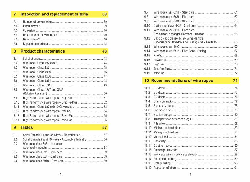
2.1.3 Direction and Lay Type
When the strands are laid from left to right, it is said that the wire rope is “right lay” (Z).
When the strands are laid from right to left, it is said that the wire rope is “left lay” (S).
The use of the left lay rope is uncommon in the majority of applications. All the characteristics of the application must be considered before specifying a left rope.
In the regular lay rope, the strand wires are laid in the opposite direction to the lay of the strands themselves. As a result, the wires from the top of the strands are positioned approximately parallel to the longitudinal axis of the wire rope. These ropes are stable, have
a good resistance to internal wear and twisting and are easy to handle. They also have a considerable resistance to kneading and warping due to short length of the exposed wires.
In the Lang lay rope, the strand wires are laid in the same direction to the lay of the strands themselves. The external wires are positioned diagonally to the longitudinal axis of the wire rope and with a greater exposure length than in the regular lay. Due to the fact of the external wires having a greater area exposed, the Lang lay provides greater resistance to abrasion to the wire rope. They are also more flexible and have greater resistance to fatigue. They are also more subject to internal wear, distortion and warping and have a low resistance to kneading. Moreover, the Lang lay wire rope must always have their ends permanently attached to prevent their distortion and, on this account, are not recommended to move loads with only a single line of rope.
Note: Except for special cases (such as, for instance, airlines tractor rope), Lang lay ropes with fibre core must not be used on account of presenting poor stability and small resistance to kneading.
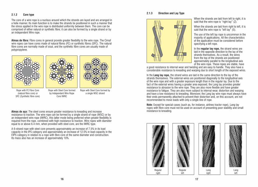
2.1.2 Core type
The core of a wire rope is a nucleus around which the strands are layed and are arranged in a helix manner. Its main function is to make the strands be positioned in such a manner that the stress applied in the wire rope is distributed uniformly between them. The core can be comprised of either natural or synthetic fibre; it can also be formed by a single strand or by an independent Wire rope.
Almas de fibra: Fibre cores in general provide greater flexibility to the wire rope. The Cimaf wire ropes can have cores made of natural fibres (FC) or synthetic fibres (SFC). The natural fibre cores are normally made of sisal, and the synthetic fibre cores are usually made of polypropylene.
Almas de aço: The steel cores ensure greater resistance to kneading and increase resistance to traction. The wire rope can be formed by a single strand of rope (WSC) or by an independent wire rope (IWRC), this latter mode being preferred when greater flexibility is required from the rope, combined with high resistance to traction. Wire ropes with diameter equal to or above 6.4 mm, when provided with steel core, are the IWRC type.
A 6-strand rope with steel core presents approximately an increase of 7.5% in its load capacity in the IPS category and approximately an increase of 12.5% in load capacity in the EIPS category in relation to a rope with fibre core of the same diameter and construction. Its mass also has an increase of approximately 10%.
Regularright
Regularleft
Langright
Langleft
Rope with FC Fibre Core(natural fibre core) or
SFC (Synthetic fibre core)
Rope with Steel Core formed by Independent Wire Rope
Core IWRC
Rope with Steel Core formed by a single WSC strand

1918
2.2 Rope lay lengthIt is defined as lay length of a wire rope the distance, measured parallel to the rope axis, required so that a strand makes a full turn around the rope axis.
2.3 Lubrification Rope lubrication is very important for its protection against corrosion and also to reduce wear by friction by the relative movement of its strands, the wires and the wire rope against the equipment parts, such as, for instance, sheaves and drums.
The Cimaf wire ropes are lubricated during the manufacturing process as a lubricant composed especially for each kind of application.
This lubrication is adequate only for a storage period and operations star t-up of the wire rope.
For good rope conservation, it is recommended to lubricate it on a regular basis.
If an adequate lubrication plan is not carried out, the wire rope will be subject to:
• Theoccurrenceofoxidationwithporositycausinglossofmetalareaand,consequently, loss of load capacity;
• Thewiresstarttobecomebrittle,duetotheexcesscorrosion;
• Asthewireropewiresmoverelativelyagainstoneanother,duringuse,theyaresubjectto wear by friction. Lack of lubrication intensifies wear, causing loss of wire rope capacity caused by loss of metal area;
• Porosityalsocausesinternalwearofthewires,resultinginlossofloadcapacity.
Lubrication of a wire rope is just as important as lubrication of a machine.
Never use burnt oil to lubricate a Wire rope, for it contains small metal particles which will cause friction with the rope, in addition to being an acid product and contain few of the characteristics which a good lubricant must have.
Overhead Crane
Whinch
Work SiteElevator
Rocker Arm
Derrick
Loop
Cableway
Fishing
Passenger Elevator
ROCOL RD-105
GCA-2
COSMOLUBEHT 00 M3
CHASSIS 1234
CHASSI Ca-2
CHASSI 2
2C
QUIMATIC 20
BIOFLUKE
Calcium Soap withmolybdenium disulfide
Bentone Soap withmolybdenum disulfide
Calcium Soap
Calcium Soap
Calcium Soap
Calcium Soap
Biodegradable
Paraffinic mineral oil
ITW
Lubrax
Houghton
ESSO
Texaco
Ipiranga
Manguinhos
Fluke Tecnologia
TAPMATIC
Application Specification Properties Supplier
LAY LENGTH
A lubricant which is adequate for wire rope must have the following characteristics:
• Tobechemicallyneutral;• Tohavegoodadherence;• Tohaveviscositycapableofpenetratingbetweenthestrandsandotherwires;• Tobestableunderoperationalconditions;• Toprotectagainstcorrosion;• Tobecompatiblewiththeoriginallubricant.Before re-lubrication, the rope must be cleaned with a steel brush to remove the old lubricant and crusts containing abrasive particles. Never use solvents, for they remove the internal lubrication, in addition to deteriorating the fibre core.
The rope must be re-lubricated just after being cleaned.
Due to the small space between the strand wires and the strands in the wire rope, during re-lubrication, the lubricant being applied will have difficulty in fully penetrating the wire rope.
As a general rule, the most efficient and cost-effective form of re-lubrication is through a method which applies the lubricant continuously during the rope operation, such as: immersion, dripping and spraying.
It is recommended that the lubricant application point is preferably where the wire rope passes through sheaves or drums, for at this moment, an opening occurs between the strands on the top part of the wire rope, favoring lubricant penetration.
In the table below we suggest a few lubricants, for field re-lubrication.
notes:
• Theperformanceofthelubricantsfromthetablewasanalyzedinthefield.Othersimilarspecificationscanbeused.
• TheselubricantsarenotcommercializedbyCimaf.
Please consult our technical assistance for further information.
2120
2.5 Wire rope strength
The aggregate breaking force of the wire rope is obtained by means of the wire strength multiplied by the total section area of all the wires.
The minimum breaking force of the wire rope is obtained by means of its aggregate breaking force, multiplied by the spinning loss factor. This factor varies according to the various classes of wire ropes.
The measured breaking force is determined in laboratory, by means of wire rope traction.
.
The forces indicated on the tables of the Cimaf technical manual always represent the rope’s minimum breaking force.
Spinning loss factor
0,960,940,860,8250,800,730,72
Rope class
Spiral Strand 3 and 7 wiresSpiral Strand 19 and 37wires
6x76x19, 8x19 and MinePac
PowerPac, 6x36ErgoFlex and ErgoFlex Plus
18x7
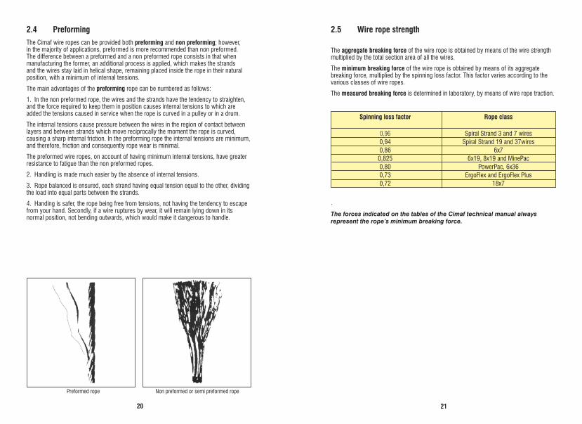
Preformed rope Non preformed or semi preformed rope
2.4 PreformingThe Cimaf wire ropes can be provided both preforming and non preforming; however, in the majority of applications, preformed is more recommended than non preformed. The difference between a preformed and a non preformed rope consists in that when manufacturing the former, an additional process is applied, which makes the strands and the wires stay laid in helical shape, remaining placed inside the rope in their natural position, with a minimum of internal tensions.
The main advantages of the preforming rope can be numbered as follows:
1. In the non preformed rope, the wires and the strands have the tendency to straighten, and the force required to keep them in position causes internal tensions to which are added the tensions caused in service when the rope is curved in a pulley or in a drum.
The internal tensions cause pressure between the wires in the region of contact between layers and between strands which move reciprocally the moment the rope is curved, causing a sharp internal friction. In the preforming rope the internal tensions are minimum, and therefore, friction and consequently rope wear is minimal.
The preformed wire ropes, on account of having minimum internal tensions, have greater resistance to fatigue than the non preformed ropes.
2. Handling is made much easier by the absence of internal tensions.
3. Rope balanced is ensured, each strand having equal tension equal to the other, dividing the load into equal parts between the strands.
4. Handing is safer, the rope being free from tensions, not having the tendency to escape from your hand. Secondly, if a wire ruptures by wear, it will remain lying down in its normal position, not bending outwards, which would make it dangerous to handle.
22
2.6 How to make an orderThe following must be pointed out when consulting or ordering wire ropes:
1. Diameter;2. Construction (number of strands, wires e composition: Seale, Filler or other);3. Core type (fibre or steel);4. Lay (regular or Lang / right or left)5. Preforming (preformed, non preformed or semi preformed);6. Lubrication (with or without lubrication);7. Category of resistance to traction of wires (PS, IPS, EIPS, EEIPS) or a Minimum
Breaking Force (Fmim);8. Finishing (bright or galvanized);9. Indication of application;10. Length
Note: When the finish is not indicated, it is understood as “bright”.
Example of order:
Wire rope 19 mm, 6x41 Warrington-Seale + IWRC, Right Regular Lay, preformed, lubricated, IPS resistance and length 500 m. Use in overhead crane.
In addition to the ABNT standards, our products fulfill the strictest international standards, such as:
•API - American Petroleum Institute
•IRAM - Instituto Argentino de Racionalización de Materiales
•FS - Federal Specification
•ASTM - American Society for Testing and Materials
•BSI - British Standard Institution
•CESA - Canadian Engineering Standard Association
•DIN – Deutsches Institut für Normung
•ISO - International Organization for Standardization
•EN - European Standard
•among others

23
3.1 Working loads limit and design factors
Note: The reference Minimum Breaking Force (Fmim) is also known as Minimum Breaking Load (MBL).
Working load limit is the maximum load that the wire rope is authorized to support.
The design factor (DF) is the ratio between the minimum breaking load (MBL) of the rope and the working load limit (WLL), i.e.:
An adequate design factor will ensure:
- Safety in load movement operation;
- Performance and durability of the wire rope and, consequently, cost effectiveness.
The table below recommends the minimum design factors (DF) for various applications:
The values on the table are reference, being that each application has normalized values.
Static ropes and spiral strands
Rope for pulling in the horizontal direction
Winches, cranes, bulldozers
Overhead cranes
Electric hoists
Stationary crane
Slings
Work site elevators
Passenger elevators
3 to 4
4 to 5
5
6 to 8
7
6 to 8
5
8 to 10
12
Applications Design Factors
3 Properties of the wire rope

2524
Construction of the wire rope or strand “F” Factor
8X19 Seale, 8x25 Filler 0,359MinePac 0,3746x7 0,3956x19 M 0,3966x31/ 6x36 / 6x41 Warrington Seale 0,4106x19 Seale 0,4166x25 Filler 0,41818x7 Rotation Resistant 0,426Spiral Strand 7 wires 0,589Spiral Strand 37 wires 0,595Spiral Strand 19 wires 0,600
Class E (Kgf/mm2)6 x 7 9.000 a 10.0006 x 19 8.500 a 9.5006 x 36 7.500 a 8.5008 x 19 6.500 a 7.5006 x 7 10.500 a 11.5006 x 19 10.000 a 11.0006 x 36 9.500 a 10.5007 wires 14.500 a 15.50019 wires 13.000 a 14.00037 wires 12.000 a 13.000
Wire ropes fibre core
Wire ropes steel core
Spiral Strands
P X LL =
E X Am
L = elastic stretches
P = applied load
L = length of rope
E = modulus of elasticity
Am = metal area
A = F x d2
:
3.2 Constructional Stretch of the wire ropesPre-stretched Ropes
There are two kinds of longitudinal stretches in wire rope, i.e.: constructional and elastic.Constructional Stretches
Constructional stretches is permanent and starts just after a load is applied to the wire rope. It is motivated by the adjustment of the wires in the rope strands and by the settling of the strands in relation to its core.
Constructional stretches occurs in the first days or weeks of service of the wire rope, depending on the applied load. On the conventional wire ropes, its value varies approximately from 0.50% to 0.75% of the length of the wire rope under load.
Constructional stretches can be almost totally removed through pre-stretching of the wire rope. The pre-stretching operation is done by a special process and with a load which must be greater than the rope’s working load limit, and lower than the load corresponding to its elastic limit.
In certain installations, such as, for instance, in “Blast Furnace Skip”, the elongation of the wire rope can not exceed a certain limit; it must be “pre-stretched”. It s also usual to pre-stretch the rope to be used in suspension bridges or similar services.
Cimaf is capacitated to pre-stretch wire ropes with diameters up to 58 mm.
Elastic Stretches
A deformação elástica é diretamente proporcional à carga aplicada e ao comprimento do cabo de aço, e inversamente proporcional ao seu módulo de elasticidade e área metálica.
The metal area of a wire rope varies as a function of the construction of the wire rope. It is comprised by the sum of the cross-section areas of the individual wires which compose it, except for filler wires.
The calculation of the metal area of a wire rope or strand can be done by means of the formula below. Although this calculation is not exact, its result is very approximate.
Where,
A = metal area in mm2; F = multiplication factor given in the following table; d = nominal diameter of the wire rope or strand in millimeters.
Notes: • Forropeswith6strandswithIWRCadd15%tometalarea;withWSCadd20%andfor
ropes with 8 strands with IWRC add 20% to its metal area.• Ingeneral,theelasticstretchofawireropecanbeestimatedon0.25%to0.50%,
when the same is submitted to a tension corresponding to 1/5 of its breaking force, depending on its construction.
Note: • Elasticstretchisproportionaltotheappliedloadaslongasitdoesnotexceedthe
elastic limit value of the rope. This limit for usual wire rope is approximately 55% a 60% of its minimum breaking load.
Modulus of elasticity of wire ropes: the modulus of elasticity of a wire rope increases during its service life, depending on its construction and the conditions under which it is operated, such as intensity of the applied loads, constant or variable, bends and vibrations to which it is submitted.
The modulus of elasticity is smaller on the new or unused ropes, being that for used or new pre-stretched ropes, the modulus of elasticity increases approximately 20%.
Next we provide the approximate modulus of elasticity of the usual constructions of new wire ropes.

26
Certo Errado
3.3 Diameter of a wire ropeThe nominal diameter for the rope is the one by which it is designated.
The actual diameter for the rope must be obtained measuring in a straight part of rope, in 2 positions with minimum spacing of 1 m. Two measurements must be taken in each position, with a 90°offset, of the circumscribed circle diameter. The average of these 4 measurements must be the actual diameter.
The actual diameter will be the average of four measured values..
Note: Measuring close to the ends of the wire rope must be avoided (minimum 10 times the rope diameter).The tolerance of diameter for wire ropes must fulfill all the recommendation of standard ABNT NBR ISO 2408, as below:
Nominal diameter of the wire rope
dmm
Tolerance as percentage of the nominal diameter
Wire ropes with strands solely of wires which incorporate solid polymer cores
2 ≤ d < 4 +8 0
4 ≤ d < 6 +7 0
6 ≤ d < 8 +6 0
≥ 8 +5 0
Note: Specific applications can have special tolerances of diameters, defined by the customer or by Cimaf. In this case consult our technical assistance.
27
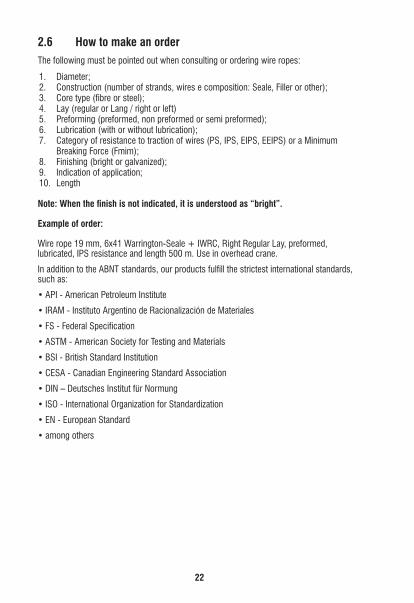
4.1 Choice of construction as a function of the applicationThe flexibility of a wire rope is inversely proportional to the diameter of its external wires, while the resistance to abrasion is directly proportional to this diameter. As a consequence, a composition with fine wires can be chosen when the bend fatigue stress prevails, and a composition of thicker external wires when the work conditions require great resistance to abrasion.
The table below stands as a general rule.
By the table above, the 6x41 WS construction wire rope is the most flexible one, thanks to the smaller diameter of its external wires; however, it is the least resistant to abrasion, while the contrary takes place with the 6x7 construction wire rope.
4.2 Diameters of sheaves and drumsThere is a relation between the diameter of the wire rope and the diameter of the sheave or drum which must be observed, so as to ensure a good wire rope performance.
The following table indicates the proportion recommended between the diameter of the sheave or the drum and the diameter of the wire rope, for the various constructions.
Note: For some equipment, there is a regulating standard from the Ministry of Labor and Employment which determines the diameter of the sheave or the drum
6 x 41 Warrington-Seale6 x 36 Warrington-Seale6 x 25 Filler6 x 21 Filler6 x 19 Seale6 x 7
Maximum flexibility
Minimumflexibility
Minimum resistanceto abrasion
Maximum resistanceto abrasion
4 Recommendations for using
Rope construction Diameter of the Sheave or DrumRecommended Mínimum
6x7 72 42 x Ø do cabo6x19 S 51 34 x Ø do cabo19x7 51 34 x Ø do cabo6x25 F 39 26 x Ø do cabo8x19 S 39 26 x Ø do cabo6x36 WS, Propac 34 23 x Ø do cabo6x41 WS 31 20 x Ø do caboPowerPac, MinePac 31 20 x Ø do caboErgoflex, Ergoflex Plus 31 18 x Ø do cabo6x71 WS 21 14 x Ø do cabo

2928
α
β
Ø OF THE GROOVE
30º - 60º
Ø OF
THE
SHE
AVE
Ø GROOVE OF THE NEW OR MACHINED SHEAVEWIRE ROPEØ OF THE WORN GROOVE
WEAR OF THE SHEAVE GROOVE MAKES MACHINING OR REPLACEMENT OBLIGATORY
Diameters indicated for sheaves and drums per type of equipment
D = Diameter of the sheave or drum
d = Diameter of wire rope
(ISO 4308) Sheave groove – For optimum rope life, the sheave groove profile should be correctly matched to the rope diameter. The groove radius, should lie within the range 0,525d to 0,550d, with 0,537d, where d is the nominal rope diameter.
4.3 Fleet angleAccording to the recommendations of the standards, the fleet angle of wire rope in the segment between the sheave and the drum must not exceed;
• a = 1° 30’ for conventional wire ropes (Classes: 6x7, 6x19, 6x36, 8x19, 8x36), with winding in drums with no groove drums.
• β= 2° Rotation resistant wire ropes, with winding in drums with groove drums;
• β= 4° for conventional wire ropes (Classes: 6x7, 6x19, 6x36, 8x19, 8x36), with winding in drums with grooved drums.
When a rope is coiling in multiple layers on the drum, the fleet angle at the flanges should be greater than 0.5° to avoid rope pile-up.
These recommendations seek to prevent the wire rope from being damaged, for if the fleet angle is greater that the maximum indicated, we will have two inconveniences:
• Thewireropewillmaintainsharpfriction with the sheave flange increasing the wear of both;
• Duringowinding,thewirerope will maintain sharp friction with the adjacent turn already wound in the drum increasing its wear and promoting damage which will influence its service life, as well as its safety.
Although a recommendation was presented regarding the wire ropes fleet angle on the sheave segment with the smooth drum (with no grooved drums), the standards recommend that all the hoisting equipment must be equipped with a drum with grooved drums. This recommendation is due to the fact of the inconvenience of the wire rope, when wound, it leaves voids between the winding turns on the drum, making the upper layer go into these voids providing a disordered winding and, as a consequence, influencing its service life and safety.
Tipe of equipment Standard ApplicationDrum Sheave
D/d minimum
Hoisting
Elevation of boom
Block
Hoisting
Hoisting
DragD
rilling
Hoisting
Traction
Compensation
18
15
---
18
24
22
20
18
40
-
18
15
16
18
24
22
30
18
40
32
ASMEB30.5
ASMEB30.3
ANSIM11.1
API SPEC 9B
API SPEC 9B
ASMEA17.1
Crane
Derrick
Bulldozer
Rotating drill
Offshore crane
Passenger Elevator
30

31
5.1 How to handleThe wire rope must be handled with care so as to avoid throttling (knot), causing a harmful twist as show in the example below:
The wire rope must never be allowed to take the shape of a loop as shown in figure 1. However, a knot can be avoided if the loop is promptly undone (opened).
As shown in figure 2, with the loop closed, the damage is done and the load capacity of the wire rope compromised, and the same being out of the conditions for use.
Figure 3 shows the result of the knot, for, even if the individual wires have not been damaged, the wire rope loses its proper shape. With the wires and the strands out of position, the wire rope is subject to uneven tension, exposing it to rupture by overload, in addition to causing excessive wear to the displaced strands.
Caution: even if a knot is apparently straightened, the wire rope can never provide maximum performance, according to the assured capacity. The use of a wire rope with this defect is dangerous and can cause accidents.
To avoid a knot when unwinding the wire rope, the reel must be placed in a horizontal axis on two sawhorses, on which it turns around its axis, as shown in figure 4.
4
5 Handling
2
3
1

3332
Rope with lay direction to the right
Rope with lay direction to the left
Top winding fromleft to right
Bottom winding fromright to left
Top winding from right to left
Bottom winding from left to right
Wrong - Figure 6
Correct - Figure. 5
It can also be unwound by means of a rotary table, as shown in figure 5. It is important that when unwinding, the reel always turns around its axis and never the wire rope turns around the reel axis, as shown in figure 6.
5.2 Winding in smooth drum or reelIt is important that the wire rope, to be well wound, is attached correctly during its installation.
If this does not happen, the first winding layer can present faults, causing, consequently, when the top layers are wound, kneading and warping in the wire rope, which will notably reduce its service life.
The figures below present a practical rule for the correct attachment of the practical rule for the correct attachment of the wire rope on smooth drums or reels.
34

35
The confection of a splice requires careful and skilful work. The perfect settling and positioning of the strands in the splice segment is important.
It is recommended that a splice length is between 1,000 to 1,500 times the diameter of the wire rope.
The essential basis of the splicing process is show in the following example:
The example refers to splicing two wire ropes with a diameter 20 mm, with 6 strands, fibre cores and preformed. A splice length of 20 mm x 1,200, i.e., 24 m was adopted in this example.
Phase 1: Both wire ropes will be well tied a distance about 12 m from their ends (2x12 m = 24 m of length required for the splice).
Phase 2: The strands from the two wire ropes will be separated at their ends up to the tie point. The strands from one of the wire ropes will be named successively “A-F” and from the other “a-f”. The strands “B,D,F” and the “a,c,d,” will be shortened and the fibre core will be cut at the tie height.
CB
A
D
FE
c
b a
df
e
CB
A
D
FE
c
b a
df
e
6 Wire rope splicing

3736
Phase 3: The ends of the wire ropes will be pushed one against the other for the strand “A” to stay beside strand “a”, strand “B” beside strand “b”, and so on.
Phase 4: The ties will be released. Strand “a” will be twisted outwards of the assembly in a length of 10 meters, and strand “A” shall be twisted into the respective empty space. Strands “B” and “b” shall proceed in the same manner.
Phase 5: Strands “c” and “D” shall twisted outwards from the ends of the respective wire ropes, in a length of 6 meters, and strands “e” and “F” a length of 2 meters, counting from the point of joining the wire rope, and the respective strands will be twisted into the spaces previously emptied.
Phase 6: The figure above shows the part corresponding to the splice when ready.
Care is required with the splices. A badly done splice represents a great hazard.
For more information, please consult our Technical Department.
B
b
A
aC
c
D
FE
df e
B
b
A
a
C
c
E
e
F
f
D
d
A
BCb
a
c
D
F
E
d
f e
B
b
A
aC
c
D
FE
df e
B
b
A
a
C
c
E
e
F
f
D
d
A
BCb
a
c
D
F
E
d
f e
B
b
A
aC
c
D
FE
df e
B
b
A
a
C
c
E
e
F
f
D
d
A
BCb
a
c
D
F
E
d
f e
B
b
A
aC
c
D
FE
df e
B
b
A
a
C
c
E
e
F
f
D
d
A
BCb
a
c
D
F
E
d
f e
38

39
Inspection in wire ropes is of the utmost importance for an adequate and safe service life.
The first inspection to be done in a wire rope is the Receival Inspection, which must assure that the material is as requested and has a certificate of quality issued by the manufacturer.
In addition to the Receival Inspection, two other inspections must be carried out, the Visual Inspection and the Periodic Inspection.
The Visual Inspection must be performed on a daily basis on the wire ropes used in load movement equipment and before each use for the loops. The purpose of this inspection is a visual analysis to detect damages on the wire rope which can cause hazards during the use. Any suspicion regarding the material safety conditions must be informed and the wire rope inspected by a qualified person.
The frequency of the Periodic Inspection must be defined by factors such as: type of equipment, environmental conditions, operating conditions, results of previous inspections and time of service of the wire ropes. For the wire ropes slings, this inspection must be done at intervals not in excess of six months, having to be more frequent when it approaches the end of its service life. It is important that the results of the inspections are recorded.
Whenever an incident occurs which may have caused damages to the rope or when it has been out of service for a long time, it must be inspected before the beginning of the job.
On inspecting a wire rope, several factors which can affect its performance must be considered. The factors to be checked for during the inspection are:
7.1 Number of broken wiresThe broken of wires normally occurs by abrasion or by bending fatigue. It can occur both in the external and internal wires, if the wire rope has a steel core. The external ruptures can occur on top of the strands or in the region of contact between the strands (valley) this one being, together with the ruptures of the core wires, the most critical.
The location of the rupture and the number of wires in a lay length must be recorded. It must be observed that if the ruptures are distributed evenly or if they are concentrated in just one or two strands. In this case, the danger exists of the strands breaking.
7.2 External wearThe abrasion of the external wires is caused by friction of the rope, under pressure, with the channels of the sheavess and the drum and it can be sped up by lubrication deficiencies.
Even if the wire does not break, it wear will promote the loss of the load capacity of the wire rope by reducing the metal area, making its use dangerous.
A form of evaluating the wear of a wire rope is by measuring its diameter.
7 Inspection and replacement criteria

4140
When this deformation is sharp, they can change the original geometry of the wire rope causing imbalance of stresses between the strands and, consequently, its rupture.
The most common deformation are:
a) Waviness
Occurs when the longitudinal axis of the wire rope takes on the shape of a helix. In situations where this anomaly is sharp, it can transmit a vibration on the wire rope which, during work, will cause premature wear, as well as broken wires.
b) Crush
Crush on the wire rope is normally caused by the disorderly winding on the drum. In situations where the disorderly winding can not be avoided, the use of wire rope with steel core must be chosen.
c) Birdcaging
This warping is typical in wire rope with steel core in situations where a sudden release of tension takes place. This irregularity is critical and prevents the wire rope from continuing to be used.
d) Core protusion
It is a characteristic also caused by the sudden release of tension of the wire rope, causing an imbalance of tension between the strands, preventing it from continuing to be used.
7.3 CorrosionCorrosion decreases the load capacity by reducing the metal area of wire rope, in addition to accelerating fatigue.
It can be detected visually, when it shows up on the external part of the wire rope.
Detection of internal corrosion is more difficult; however, a few indications can point out its existence:
• Variation in rope diameter: the decrease of diameter usually takes place in the folding points of the wire rope. In wire ropes or strands for static use, the increase of diameter is common due to the increase of oxidation.
• Approximation between strands: frequently combined with broken wires in the valleys
7.4 Unbalance of the wire ropesIn conventional wire ropes, normally with 6 or 8 strands with fibre core, a typical damage can happen which is a ripple of the wire rope cased by the sinking of 1 or 2 of its strands and it can be caused by a few motives:
a) Poor attachment, which allows a few strands to slide, the remaining ones being overtensioned.
b) Fibre core of reduced diameter.c) Fibre core which deteriorate, giving no support to the strands of rope.
On ropes with several layers of strands, as in the resistant to rotation ropes and ropes with steel core, the danger of “birdcaging”” and “raised core” exists, defects which can be caused by the following motives:
d) Poor handling and/or installation of rope, giving rise to torsions or distortions of the same.
In case “a” the danger exists of the overtensioned strands breaking; in cases “b” and “c”, there is no imminent danger, however, there will be an uneven wear in the wire rope and, therefore, low efficiency.
Case “d” is more common for Non-Rotating ropes and with Steel Core, where the danger of “birdcaging”” and “raised core” exists. These defects are grave and require prompt replacement of the wire rope.
7.5 Deformation*Deformation in the wire ropes occurs mainly due to misuse or irregularities in the equipment or, further, by inadequate methods of handling and attaching.

42
e) Kink or knot (dog leg)
It is characterized by a discontinuity in the longitudinal direction of the wire rope which in extreme cases reduces its load capacity. It is normally caused by improper handling or installation.
7.6 Replacement criteriaEven if the wire rope works in optimum conditions, a moment comes in which, after reaching the end of its service life, it needs to be replaced by virtue of its natural degeneration.
In any installation, the problem consists in determining what is the maximum efficiency which can be obtained from a wire rope before replacing it, to keep it working in complete safety, since, in the greater portion of the installations, the breaking of a wire rope puts human lives at risk.
There isn’t a precise rule to determine the exact moment for replacing a wire rope. The decision of a wire rope remaining in service will depend on the evaluation of a qualified person, who must compare its conditions, carrying out an inspection based on disposal criteria contemplated in standards. The following standards are recommended:
• NBRISO4309,forequipment.
• NBR13541-2forslings.

43
8 Product characteristics
Construction Table Page
Characteristics
Used in stays, tie rods, messenger ropes and similar uses.
Used in the automobile industry and similar purposes.
Used in the automobile industry to breaks, clutches and other mechanical purposes.
Used in the automobile industry and similar purposes.
57
58
58
57
8.1 Spiral strands
19 wires(1+6/12)37 wires
(1+6/12/18)
7 wires 1+6
19 wires 1+6/12
37 wires (1+6/12/18 )

4544
Construction Table Page
Characteristics
Wire ropes of 6 strands with 5 to 9 wires in each strand.They have excellent resistance to abrasion and to pressure and low flexibility, its application being limited. Normally, it is manufactured with fibre core; it can be manufactured with steel core.Used in operations where it is subject to friction during the operation and also for static purposes, such as stays.
59
6x7+AF1+6
6x7+AAor 7x71+6
6x7+AACI1+6
Construction Table Page
Characteristics
Used in the automobile industry, for raising the window. 58
8x7+AA 1+6
6x7+AA or 7x7 1+6
8.2 Wire rope - Class 6x7 e 8x7 8.3 Wire rope - Class 6x7

4746
Wire ropes of 6 strands with 29 to 57 wires in each strand.The great number of wires of the ropes of this class makes the rope highly flexible.The ropes of this class, in the most common diameters, adapt well in applications where they have to work dynamically on drum and pulleys. In larger diameters, this class has excellent resistance to abrasion and to kneading, sufficient for the most critical operations.
6x36+AF Warrington-Seale 1+7+(7+7)+14
6 x 41 + AACI Warrington-Seale 1+8+(8+8)16
6 x 41+AF Warrington-Seale 1+8+(8+8)+16
62to63
Construction Table Page
Characteristics
Wire ropes of 6 strands with 15 to 26 wires in each strand.They have good resistance to bending and good resistance to abrasion.This class is one of the most used, offering the most adequate constructions for the greater portion of the applications in the most common diameters.Specialcaremustbetakenwith6x19Mconstructionwireropes.Theyarereccomendedforstaticapplicationonly.
60and61
6x19+AACI Seale
1+9+9
6x19+AF Seale
1+9+9
6x25+AACI Filler
1+6+6+12
Construction Table Page
Characteristics
8.4 Wire rope - Class 6x19 8.5 Wire rope - Class 6x36

4948
Wire ropes of 8 strands with 15 to 26 wires in each strand.In this class, the ropes are usually manufactured with FC.Due to the relatively large size of the core, necessary for manufacturing this class, this wire rope is more susceptible to flattening when submitted to a high pressure in the pulley and drum; thus, its use is recommended in operations with moderate loads.The greater portion of the passenger elevators uses wire ropes with diameters between 9.5 mm and 16.0 mm, in this class.
65 8x19+AF
Seale 1+9+9
Construction Table Page
Characteristics
Wire ropes of 6 strands with 61 to 85 wires. These ropes are usually manufactured in diameters above 90 mm, where the great number of wires ensures good flexibility.
64
6x71+AACIWarrington-Seale
1+6+8+(8+8)+16+24
Construction Table Page
Characteristics
8.6 Wire rope - Class 6x61 8.7 Wire rope - Class 8X19

5150
Manufactured with 34 compacted strands, the ErgoFlex wire rope is composted of 7 wires in each strand and steel core.
The ErgoFlex was especially developed for equipment that works in applications where the hoisting height is critical, such as, for instance:
• Fixedderricks,telescoping,erectingandextending boom.
• Towercranesusedinshipsandoilrigs• Equipmentwithonlyasinglelineofropefor
hoisting loads• Systemswithmorethanonelayerofwinding
on the drum
In addition to its excellent anti-rotating property, we can highlight:
• HighMinimumBreakingForce• Highflexibilityduetotheconstruction
characteristics• Highresistancetofatigueduetothe
compacting of the strands• Galvanizedfinishreducingthelevelofoxidation
and increasing the resistance to fatigue by bending
Note: All the cares pointed out in the previous page must be taken as a reference.
70
35xK7 1+6
Construction Table Page
Characteristics
The rotation resistant wire ropes are usually manufactured with 12 external strands of 7 wires each with regular right lay, laid around a nucleus composed of 6 strands of 7 wires each with Lang left lay which in turn are laid around a core which can be made of fibre or steel.
The term “Rotation Resistant”, is due to the smaller tendency of turning of this wire rope which is grounded in the inversion of lay between the layers of external and internal strands, annulling the torsion moment under tension.
The ropes of this class twist a little in the beginning of applying the load, until it stays in balance.
The rotation resistant wire ropes must be used with great care and with design factors higher than the other classes.
Special care recommended in the use of Rotation Resistant ropes:
1) The general instructions for handling wire ropes must be followed, preventing them, both when unwinding from the reel and in installing in the machine, from suffering distortions or knots which may render them useless.
2) This wire rope is very sensitive to brusque variations of load and requires a very smooth handling. In general, there must be a weight next to the hook to keep it under tension. Most times, the brusque variations promote “birdcaging”, rendering the wire rope useless.
3) It must be avoided that the rotation resistant rope undergoes rotation during service.
4) On attaching (anchoring), it is essential that all the strands of the rotation resistant rope are well attached, including the internal ones. To achieve that, attachment by means of clips or other pressure-actuated fittings must be avoided, the use of sockets is recommended.
5) This rope must be wound on a drum with channel and sufficient dimensions to prevent overlapping of different layers.
6) The rotation resistant rope is usually recommended for equipment which works with only a single wire rope line, or further, when the equipment works with two very close rope lines, its hoisting height being very high.
Note: By virtue of the special cares which are required in installation, handling and operation of the rotation resistant ropes (18x and 19x7), it is recommended to limit is employment only to the essential cases.
66
19 x 71+6
Construction Table Page
Characteristics
8.8 Wire rope - Class 18x7 and 35x7 (Rotation Resistant)
8.9 High Performance wire ropes – ErgoFlex

5352
Manufactured with high zinc layer and artificial fibre core (SFC), promoting high resistance to corrosion, high flexibility and greater durability ensuring an excellent performance in the fishing industry.
59and67
6x19+AFA Seale
1+9+9
Construction Table Page
Characteristics
6x7+AFA 1+6
71
34xK(7+17)(1+6) / (1+8+8)
Construction Table Page
Characteristics
8.10 High Performance wire ropes – ErgoFlexPlus 8.11 Wire rope - Class 6x7 e 6x19 Galvanized
Manufactured with 33 strands and compacted core, the ErgoFlexPlus wire rope is composted of 7 wires in each external strand and steel core and 17 wires in internal each strand.
The ErgoFlexPlus was especially developed for equipment that works in applications where the hoisting height is critical, such as, for instance:
• Fixedderricks,telescoping,erectingandextending boom.
• Towercranesusedinshipsandoilrigs• Equipmentwithonlyasinglelineofropefor
hoisting loads• Systemswithmorethanonelayerofwinding
on the drum.
In addition to its excellent anti-rotating property, we can highlight:
• HighMinimumBreakingForce• Highflexibilityduetotheconstruction
characteristics• Highresistancetofatigueduetothe
compacting of the strands• Increaseofstructuralstabilityasafunctionof
the plasticized core• Galvanizedfinishreducingthelevelofoxidation
and increasing the resistance to fatigue by bending
Note: All the cares pointed out in the previous page must be taken as a reference.

5554
The PowerPac ropes were especially developed for dynamic applications, mainly for equipment such as: Port Cranes, Ship Loaders and Off-Loaders and Overhead Cranes.
In addition to its high performance, the PowerPac rope stands out due to:
1) Greater performance promoted by the compacted strands and coated core.
2) High Minimum Breaking Force.
3) Easiness of adapting to the equipment; it can be manufactured with strands of 21 to 41 wires.
4) Greater structural stability and internal corrosion protection due to the coated core.
5) Use in systems with more than one layer of winding on the drum.
69
8xK31+EPAACIWarrington-Seale1+6+(6+6)+12
Construction Table Page
Characteristics
8.14 High Performance wire ropes – MinePac
The MinePac ropes were especially developed for dynamic applications, mainly for equipment in the mining sector, such as: bulldozers (Shovel and Dragline).
In addition to its high performance, the MinePac rope stands out due to:1) Greater performance promoted by the compacted strands.2) High Minimum Breaking Force.3) Greater structural stability and internal and external corrosion protection due to complete rope coating.
72
EP8xK36+AACIWarrington-Seale1+7+(7+7)+14
Construction Table Page
Characteristics
The ProPac ropes were especially developed for dynamic applications under severe conditions, mainly for equipment such as: Overhead Cranes, Ship Loaders and Off-Loaders.
In addition to its high performance, the ProPac rope stands out due to:
1) Greater resistance to abrasion promoted strands compacted
2) High Minimum Breaking Force.
3) Use in systems with more than one layer of winding on the drum.
4) Easiness of adapting to the equipment; it can be manufactured with strands of 26 to 36 wires.
68
Construction Table Page
Characteristics
8.12 High Performance wire ropes - ProPac 8.13 High Performance wire ropes - PowerPac
6xK31+AACI1+6+(6+6)+12

56

57
9 Tables
9.1 Spiral Strands 19 and 37 wires – Electrification
Manufactured and tested in accordance with the requirements of the standards ABNT NBR 5909 and ASTM A475
DiameterConstruction Approx. Mass
(kg/m)
Minimum Breaking Force (tf)
mm in. EHS12,7 1/2" 1x19 0,77 13,0014,3 9/16" 1x19 0,98 17,0015,9 5/8" 1x19 1,22 21,0019,0 3/4" 1x37 1,76 29,0020,2 13/16" 1x37 1,98 32,8022,2 7/8" 1x37 2,40 40,0025,4 1" 1x37 3,12 50,0028,6 1.1/8" 1x37 3,96 66,00
19 wires1+6/12
37 wires1+6/12/18

5958
The value for mass indicated on the table refers to the internal standard of BBA; it can vary as a function of the wire rope lay length tolerance.
6x71+6
6x71+6
The value for mass indicated on the table refers to the internal standard of BBA; it can vary as a function of the wire rope lay length tolerance.
6x7+AA1+6
8x7+AA1+6
7 wires1+6
19 wires1+6/12
9.2 Spiral Strands 7 and 19 wires - Automobile Industry
9.3 Wire rope class 6x7 - steel core Automobile Industry
9.4 Wire rope class 6x7 - Fibre core
9.5 Wire rope class 6x7 – steel core
Diameter Approx. Mass (kg/m)
Minimum Breaking Force (tf)
mm in. IPS1,6 1/16” 0,008 0,162,4 3/32” 0,018 0,353,2 1/8” 0,031 0,614,0 5/32” 0,046 0,964,8 3/16” 0,065 1,386,4 1/4” 0,145 2,508,0 5/16” 0,235 3,809,5 3/8” 0,376 5,50
14,5 9/16” 0,725 12,30
Diameter Approx. Mass (kg/m)
Minimum Breaking Force (tf)
mm in. IPS
2,4 3/32" 0,024 0,373,2 1/8" 0,034 0,664,0 5/32" 0,065 1,044,8 3/16" 0,085 1,49
Diametermm
Spiral StrandConstruction
Approx. Mass (kg/m)
Minimum Breaking Force (tf)
IPS1,5 1x7 0,011 0,221,2 1x19 0,007 0,141,5 1x19 0,011 0,222,0 1x19 0,020 0,392,5 1x19 0,520 0,622,8 1x19 0,580 0,783,0 1x19 0,046 0,893,2 1x19 0,052 1,013,5 1x19 0,062 1,20
Diametermm
Spiral StrandConstruction
Approx. Mass (kg/m)
Minimum Breaking Force (tf)
180kgf/mm²
215kgf/mm²
235kgf/mm²
250kgf/mm²
1,5 6x7 0,011 - - 0,28 -
1,5 8x7 0,011 - - - 0,271,6 6x7 0,011 - - 0,28 -1,8 6x7 0,011 - - 0,32 -2,0 6x7 0,020 - - 0,37 -2,4 6x7 0,021 0,36 - - -

6160
6x19 Seale 1+9+9
6x25 Filler 1+6+6+12
The value for mass indicated on the table refers to the internal standard of BBA; it can vary as a function of the wire rope lay length tolerance.
The value for mass indicated on the table refers to the internal standard of BBA; it can vary as a function of the wire rope lay length tolerance.
6x19 Seale 1+9+9
6x25 Filler 1+6+6+12
9.6 Wire rope class 6x19 - Fibre core 9.7 Wire rope class 6x19 - Steel core
Diameter Approx. Mass (kg/m)
Minimum Breaking Force (tf)
mm in. IPS EIPS3,2 1/8" 0,040 0,65 0,734,0 5/32” 0,063 1,02 1,134,8 3/16" 0,096 1,46 1,646,4 1/4” 0,142 2,68 3,108,0 5/16" 0,268 - 4,809,5 3/8" 0,352 - 6,86
11,5 7/16" 0,519 - 9,3013,0 1/2" 0,685 - 12,1014,5 9/16" 0,868 - 15,2016,0 5/8" 1,058 - 18,7019,0 3/4" 1,496 - 26,8022,0 7/8" 2,036 - 36,1026,0 1" 2,746 - 47,0029,0 1.1/8" 3,447 - 59,0032,0 1.1/4" 4,192 - 72,6038,0 1.1/2" 6,009 - 103,3042,0 1.5/8" 7,120 - 122,0045,0 1.3/4" 8,368 - 141,0052,0 2" 10,921 - 183,70
Diameter Approx. Mass(kg/m)
Minimum Breaking Force (tf)
mm in. IPS EIPS
3,2 1/8" 0,036 0,61 -4,8 3/16" 0,082 1,37 -6,4 1/4" 0,142 2,50 2,738,0 5/16" 0,230 3,90 4,309,5 3/8" 0,343 - 6,1011,5 7/16" 0,479 - 8,3013,0 1/2" 0,608 - 10,8014,5 9/16" 0,775 - 13,6016,0 5/8" 0,933 - 16,8019,0 3/4" 1,298 - 24,0022,0 7/8" 1,805 29,50 32,6026,0 1" 2,442 38,50 42,6029,0 1.1/8" 3,055 - 53,9032,0 1.1/4" 3,733 60,10 66,5035,0 1.3/8" 4,529 - 80,5038,0 1.1/2" 5,328 86,50 95,8045,0 1.3/4" 8,368 - 130,4052,0 2" 9,740 - 170,30

6362
The value for mass indicated on the table refers to the internal standard of BBA; it can vary as a function of the wire rope lay length tolerance.
6x36 Warrington-Seale 1+7+(7+7)+14
6x47 Warrington-Seale 1+6/8+(8+8)+16
6x41 Warrington-Seale 1+8+(8+8)+16
The value for mass indicated on the table refers to the internal standard of BBA; it can vary as a function of the wire rope lay length tolerance.
6x36 Warrington-Seale1+7+(7+7)+14
6x41 Warrington-Seale1+8+(8+8)+16
6x47 Warrington-Seale1+6/8+(8+8)+16
9.8 Wire rope class 6x36 - Fibre core 9.9 Wire rope class 6x36 - Steel core
Diameter Approx. Mass (kg/m)
Minimum Breaking Force (tf)
mm in. IPS EIPS EEIPS6,4 1/4" 0,173 2,70 3,10 -8,0 5/16" 0,266 4,15 4,79 -9,5 3/8" 0,399 5,96 6,86 -11,5 7/16" 0,538 8,10 9,30 -13,0 1/2" 0,695 10,50 12,10 -14,5 9/16" 0,879 13,20 15,20 -16,0 5/8" 1,044 16,20 18,70 -19,0 3/4" 1,520 23,40 26,80 -22,0 7/8" 2,073 31,80 36,10 -26,0 1" 2,610 41,50 47,00 -29,0 1.1/8" 3,456 52,50 59,00 -32,0 1.1/4" 4,230 64,80 72,60 -35,0 1.3/8" 5,086 78,40 87,20 -38,0 1.1/2" 5,918 93,30 103,30 -42,0 1.5/8" 7,368 - 122,00 -45,0 1.3/4" 8,387 - 141,00 -52,0 2" 11,159 - 183,70 -57,2 2.1/4" 13,821 - 232,50 -63,5 2.1/2" 16,980 - 274,00 301,0069,9 2.3/4" 19,166 - 333,10 360,0076,2 3" 24,549 - 389,00 437,2085,7 3.3/8" 29,744 - 487,00 529,0095,3 3.3/4" 37,606 - 585,00 640,00
102,0 4" 44,000 - 595,00 647,00108,0 4.1/4" 46,919 - 667,00 725,10
Diameter Approx. Mass (kg/m)
Minimum Breaking Force (tf)
mm in. IPS EIPS6,4 1/4" 0,150 2,50 2,728,0 5/16" 0,228 3,90 4,269,5 3/8" 0,353 5,55 6,1011,5 7/16" 0,479 7,88 8,2713,0 1/2" 0,580 10,10 10,8014,5 9/16” 0,786 12,50 13,6016,0 5/8" 0,919 15,20 16,8019,0 3/4" 1,359 22,00 24,0022,0 7/8" 1,842 29,50 32,6026,0 1" 2,376 38,50 42,6029,0 1.1/8" 3,064 50,10 53,9032,0 1.1/4" 3,770 60,10 66,5035,0 1.3/8" 4,687 73,00 80,5038,0 1.1/2" 5,530 86,50 95,8045,0 1.3/4" 7,628 117,70 130,4052,0 2" 9,978 153,80 170,30

6564
* 6x19S+AFThe value for mass indicated on the table refers to the internal standard of BBA; it can vary as a function of the wire rope lay length tolerance.
Fabricados e testados de acordo com as exigências da norma ISO 4344
8x19Seale1+9+9
The value for mass indicated on the table refers to the internal standard of BBA; it can vary as a function of the wire rope lay length tolerance.
9.10 CWire rope class 6x36 - Steel core 9.11 Wire rope class 8x19 - Fibre core Special for Passenger Elevators - Traction
9.12 Cabo de aço classe 8x19 - Alma de fibra Especial para Elevadores de Passageiros - Limitador
8x19 Seale 1+9+9
6x19 Seale 1+9+9
6x71 Warrington-Seale
1+6+8+(8+8)+16+24
Diameter Approx. Mass (kg/m)
Minimum Breaking Force (tf)
mm in. 1770N/mm2
6,4* 1/4” 0,140 2,506,4 1/4” 0,145 2,528,0 5/16” 0,223 3,82
Diameter Approx. Mass (kg/m)
Minimum Breaking Force (tf)
mm in. TS8,0 5/16” 0,223 2,869,5 3/8” 0,315 4,10
11,0 - 0,445 5,4213,0 1/2” 0,560 7,6016,0 5/8” 0,880 11,55Diameter Approx. Mass
(kg/m)Minimum Breaking Force (tf)
mm in. EIPS114,0 4.1/2” 55,700 806,0121,0 4.3/4” 62,000 891,0127,0 5” 68,700 978,0

6766
The value for mass indicated on the table refers to the internal standard of BBA; it can vary as a function of the wire rope lay length tolerance..
The value for mass indicated on the table refers to the internal standard of BBA; it can vary as a function of the wire rope lay length tolerance.
19x7 1+6
9.13 Wire rope class 18x7 9.14 Wire rope class 6x19 - Fibre Core - Fishing
6x19 Seale
1+9+9
Diameter Approx. Mass (kg/m)
Minimum Breaking Force
mm in. IPS9,5 3/8" 0,340 5,6013,0 1/2" 0,590 9,8014,5 9/16" 0,770 12,3016,0 5/8" 0,940 15,2019,0 3/4" 1,298 21,70
Diameter Approx. Mass (kg/m)
Minimum Breaking Force
mm in. IPS EIPS6,4 1/4" 0,170 2,40 -8,0 5/16" 0,260 3,75 -9,5 3/8" 0,358 5,40 -11,5 7/16" 0,523 7,40 -13,0 1/2" 0,699 9,60 -14,5 9/16” 0,821 12,10 -16,0 5/8" 1,054 15,00 -19,0 3/4" 1,492 21,50 -22,0 7/8" 2,050 29,30 -26,0 1" 2,639 38,20 42,3029,0 1.1/8" 3,295 48,40 53,6032,0 1.1/4" 4,121 59,70 66,10
6968
The value for mass indicated on the table refers to the internal standard of BBA; it can vary as a function of the wire rope lay length tolerance.
The value for mass indicated on the table refers to the internal standard of BBA; it can vary as a function of the wire rope lay length tolerance.
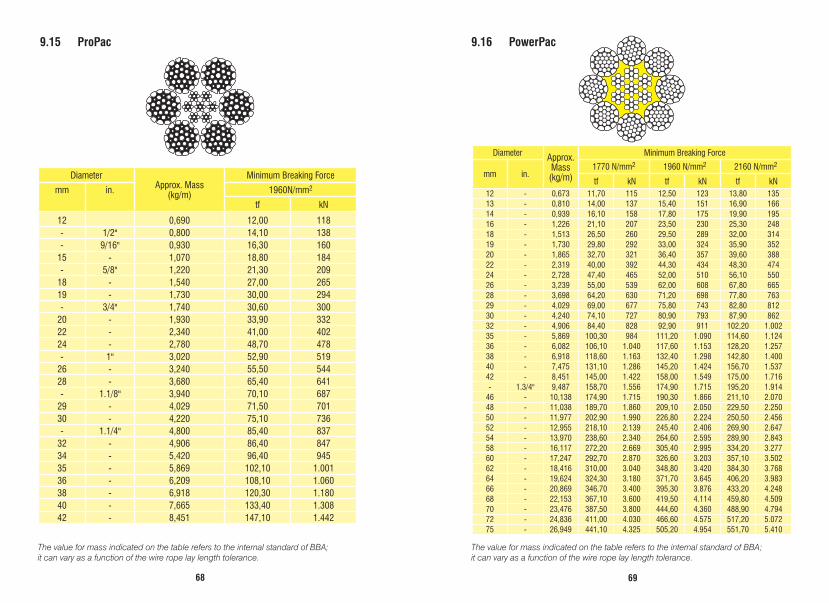
9.15 ProPac 9.16 PowerPac
DiameterApprox. Mass
(kg/m)
Minimum Breaking Force
mm in. 1960N/mm2
tf kN
12 0,690 12,00 118- 1/2" 0,800 14,10 138- 9/16" 0,930 16,30 160
15 - 1,070 18,80 184- 5/8" 1,220 21,30 209
18 - 1,540 27,00 26519 - 1,730 30,00 294- 3/4" 1,740 30,60 300
20 - 1,930 33,90 33222 - 2,340 41,00 40224 - 2,780 48,70 478- 1" 3,020 52,90 519
26 - 3,240 55,50 54428 - 3,680 65,40 641- 1.1/8" 3,940 70,10 687
29 - 4,029 71,50 70130 - 4,220 75,10 736- 1.1/4" 4,800 85,40 837
32 - 4,906 86,40 84734 - 5,420 96,40 94535 - 5,869 102,10 1.00136 - 6,209 108,10 1.06038 - 6,918 120,30 1.18040 - 7,665 133,40 1.30842 - 8,451 147,10 1.442
Diameter Approx. Mass (kg/m)
Minimum Breaking Force
mm in. 1770 N/mm2 1960 N/mm2 2160 N/mm2
tf kN tf kN tf kN12 - 0,673 11,70 115 12,50 123 13,80 13513 - 0,810 14,00 137 15,40 151 16,90 16614 - 0,939 16,10 158 17,80 175 19,90 19516 - 1,226 21,10 207 23,50 230 25,30 24818 - 1,513 26,50 260 29,50 289 32,00 31419 - 1,730 29,80 292 33,00 324 35,90 35220 - 1,865 32,70 321 36,40 357 39,60 38822 - 2,319 40,00 392 44,30 434 48,30 47424 - 2,728 47,40 465 52,00 510 56,10 55026 - 3,239 55,00 539 62,00 608 67,80 66528 - 3,698 64,20 630 71,20 698 77,80 76329 - 4,029 69,00 677 75,80 743 82,80 81230 - 4,240 74,10 727 80,90 793 87,90 86232 - 4,906 84,40 828 92,90 911 102,20 1.00235 - 5,869 100,30 984 111,20 1.090 114,60 1.12436 - 6,082 106,10 1.040 117,60 1.153 128,20 1.25738 - 6,918 118,60 1.163 132,40 1.298 142,80 1.40040 - 7,475 131,10 1.286 145,20 1.424 156,70 1.53742 - 8,451 145,00 1.422 158,00 1.549 175,00 1.716- 1.3/4" 9,487 158,70 1.556 174,90 1.715 195,20 1.914
46 - 10,138 174,90 1.715 190,30 1.866 211,10 2.07048 - 11,038 189,70 1.860 209,10 2.050 229,50 2.25050 - 11,977 202,90 1.990 226,80 2.224 250,50 2.45652 - 12,955 218,10 2.139 245,40 2.406 269,90 2.64754 - 13,970 238,60 2.340 264,60 2.595 289,90 2.84358 - 16,117 272,20 2.669 305,40 2.995 334,20 3.27760 - 17,247 292,70 2.870 326,60 3.203 357,10 3.50262 - 18,416 310,00 3.040 348,80 3.420 384,30 3.76864 - 19,624 324,30 3.180 371,70 3.645 406,20 3.98366 - 20,869 346,70 3.400 395,30 3.876 433,20 4.24868 - 22,153 367,10 3.600 419,50 4.114 459,80 4.50970 - 23,476 387,50 3.800 444,60 4.360 488,90 4.79472 - 24,836 411,00 4.030 466,60 4.575 517,20 5.07275 - 26,949 441,10 4.325 505,20 4.954 551,70 5.410

7170
The value for mass indicated on the table refers to the internal standard of BBA; it can vary as a function of the wire rope lay length tolerance.
The value for mass indicated on the table refers to the internal standard of BBA; it can vary as a function of the wire rope lay length tolerance.
9.17 ErgoFlex 9.18 ErgoFlex Plus
Nominal Diameter Approx. Mass (kg/m)
Minimum Breaking Force
mm in.1960N/mm2 2160N/mm2
tf kN tf kN22 - 2,490 45,50 446 46,00 451
24 - 2,963 54,60 535 55,60 545- 1" 3,332 61,10 599 62,20 610
26 - 3,478 63,90 627 65,10 63828 - 3,920 73,90 725 75,20 73729 - 4,184 79,20 777 80,90 79330 - 4,482 84,60 830 86,70 85032 - 5,134 96,30 944 98,70 96834 - 5,751 108,20 1.061 111,40 1.09236 - 6,380 121,50 1.191 123,30 1.20938 - 7,428 135,30 1.327 137,20 1.34540 - 7,899 150,00 1.471 152,40 1.49442 - 8,739 165,30 1.621 168,40 1.65145 - 10,417 189,80 1.861 193,60 1.898
Nominal Diameter Approx. Mass (kg/m)
Minimum Breaking Force
mm in.1960N/mm2 2160N/mm2
tf kN tf kN10 - 0,438 9,40 91,70 10,10 98,60
12 - 0,638 13,60 133 14,70 14413 - 0,750 15,90 156 17,10 16814 - 0,862 18,50 181 19,70 19315 - 1,013 21,20 208 22,90 22516 - 1,141 24,30 238 26,00 25518 - 1,418 30,40 298 32,20 31619 - 1,633 34,10 334 37,00 36320 - 1,777 37,70 370 40,30 39522 - 2,148 46,10 452 48,60 477- 7/8" 2,150 46,20 453 48,70 478
24 - 2,529 54,00 530 57,10 560- 1" 2,910 60,50 593 65,70 644
26 - 3,021 63,90 627 68,30 67028 - 3,466 73,90 725 78,20 767- 1.1/8" 3,670 76,50 750 82,30 807
29 - 3,731 79,20 777 83,90 82330 - 4,025 84,60 830 90,90 89132 - 4,578 96,30 944 103,30 1.01334 - 5,168 108,20 1.061 116,40 1.14136 - 5,829 121,50 1.191 130,50 1.28038 - 6,476 135,30 1.327 145,30 1.42540 - 7,138 150,00 1.471 160,90 1.57842 - 7,940 165,30 1.621 178,00 1.74545 - 8,960 189,80 1.861 201,90 1.980
7372
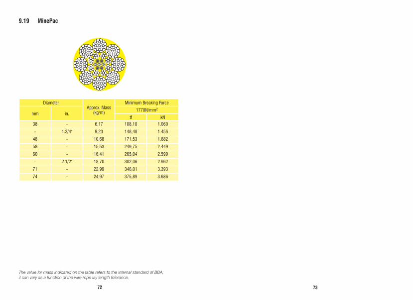
The value for mass indicated on the table refers to the internal standard of BBA; it can vary as a function of the wire rope lay length tolerance.
9.19 MinePac
DiameterApprox. Mass
(kg/m)
Minimum Breaking Force
mm in.1770N/mm2
tf kN38 - 6,17 108,10 1.060
- 1.3/4" 9,23 148,48 1.456
48 - 10,68 171,53 1.682
58 - 15,53 249,75 2.449
60 - 16,41 265,04 2.599
- 2.1/2" 18,70 302,06 2.962
71 - 22,99 346,01 3.393
74 - 24,97 375,89 3.686
7574
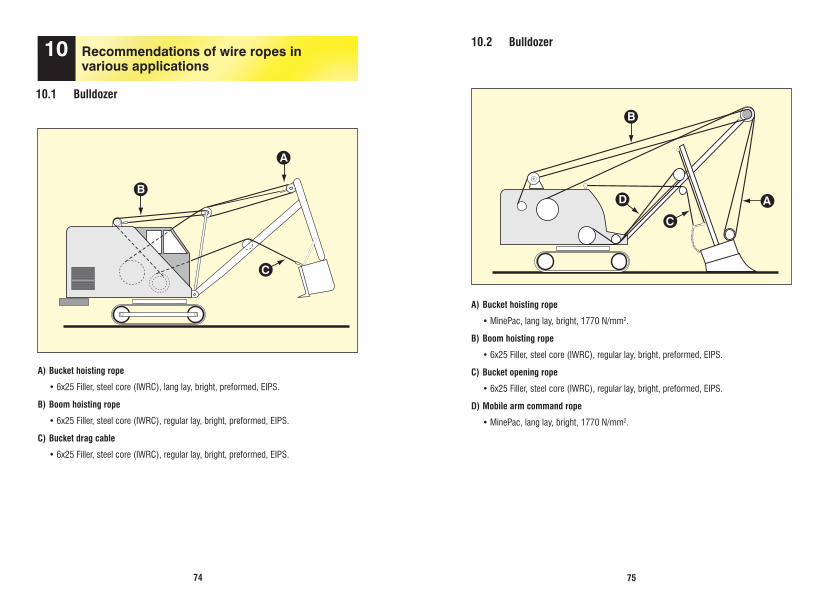
10.1 Bulldozer
10 Recommendations of wire ropes in various applications
A) Bucket hoisting rope
•6x25Filler,steelcore(IWRC),langlay,bright,preformed,EIPS.
B) Boom hoisting rope
•6x25Filler,steelcore(IWRC),regularlay,bright,preformed,EIPS.
C) Bucket drag cable
•6x25Filler,steelcore(IWRC),regularlay,bright,preformed,EIPS.
10.2 Bulldozer
A) Bucket hoisting rope
•MinePac,langlay,bright,1770N/mm2.
B) Boom hoisting rope
•6x25Filler,steelcore(IWRC),regularlay,bright,preformed,EIPS.
C) Bucket opening rope
•6x25Filler,steelcore(IWRC),regularlay,bright,preformed,EIPS.
D) Mobile arm command rope
•MinePac,langlay,bright,1770N/mm2.
B
A
C
B
A
C
D
7776
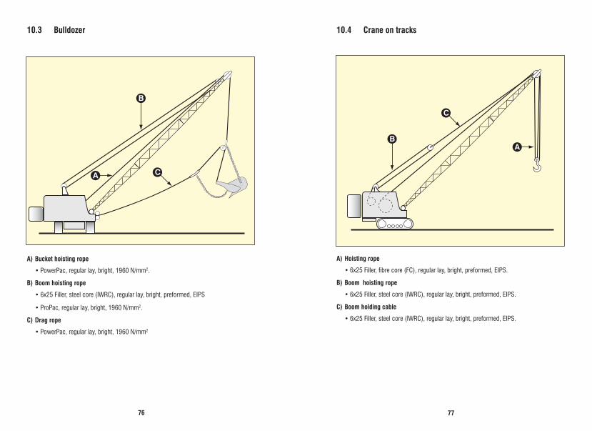
10.3 Bulldozer
A) Bucket hoisting rope
•PowerPac,regularlay,bright,1960N/mm2.
B) Boom hoisting rope
•6x25Filler,steelcore(IWRC),regularlay,bright,preformed,EIPS
•ProPac,regularlay,bright,1960N/mm2.
C) Drag rope
•PowerPac,regularlay,bright,1960N/mm2
10.4 Crane on tracks
A) Hoisting rope
•6x25Filler,fibrecore(FC),regularlay,bright,preformed,EIPS.
B) Boom hoisting rope
•6x25Filler,steelcore(IWRC),regularlay,bright,preformed,EIPS.
C) Boom holding cable
•6x25Filler,steelcore(IWRC),regularlay,bright,preformed,EIPS.
B
A C
BA
C

7978
A) Bucket hoisting rope
•Morethanonbranchofropeforhoistingload:6x25Filler,fibrecore(FC),regularlay,bright, preformed, EIPS.
If the rope is subject to kneading on the drum, use the same specifications above with steel core (IWRC).
•Onlyasingleloadhoistingrope:ErgoFlexorErgoFlexPlus.
B) Boom hoisting rope
•6x25Filler,steelcore(IWRC),regularlay,bright,preformed,EIPS.
C) Crane rotation rope
•6x41Warrington-Seale,steelcore(IWRC),regularlay,bright,preformed,IPS.
D) Tie rods
•6x7,steelcore(WSC),regularlay,bright/galvanized,preformed,IPSorEIPS.
10.5 Stationary crane 10.6 Overhead crane
A) Hoisting rope
•6x41Warrington-Seale,fibrecore(FC),regularlay,bright,preformed,IPS.
•PowerPac,regularlay,bright,1960N/mm2.
•ProPac,regularlay,bright,.1960N/mm2.
B) Rope for raising hot loads
•6x41Warrington-Seale,fibrecore(FC),regularlay,bright,preformed,IPS,
•PowerPac,regularlay,bright,1960N/mm2,
Notes:• Layrightandleftcanbeusedsimultaneouslyininstallationswhichhavetwoormore
independent ropes.• Wireropewithsteelcore(IWRC)isalsorecommendedforworkingincorrosive
atmosphere.• Wemanufactureotherconstructionsunderconsultation.
B
D
A
C
12
A
B
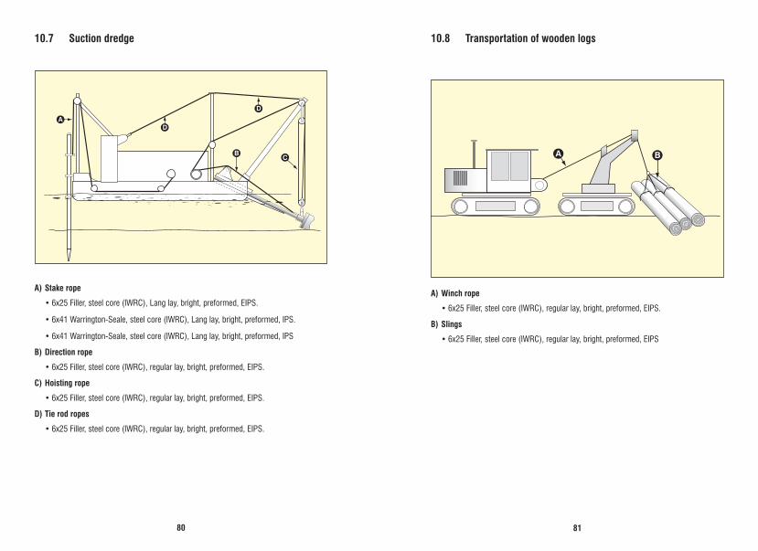
8180
10.7 Suction dredge
A) Stake rope
•6x25Filler,steelcore(IWRC),Langlay,bright,preformed,EIPS.
•6x41Warrington-Seale,steelcore(IWRC),Langlay,bright,preformed,IPS.
•6x41Warrington-Seale,steelcore(IWRC),Langlay,bright,preformed,IPS
B) Direction rope
•6x25Filler,steelcore(IWRC),regularlay,bright,preformed,EIPS.
C) Hoisting rope
•6x25Filler,steelcore(IWRC),regularlay,bright,preformed,EIPS.
D) Tie rod ropes
•6x25Filler,steelcore(IWRC),regularlay,bright,preformed,EIPS.
B
D
DA
C
10.8 Transportation of wooden logs
A) Winch rope
•6x25Filler,steelcore(IWRC),regularlay,bright,preformed,EIPS.
B) Slings
•6x25Filler,steelcore(IWRC),regularlay,bright,preformed,EIPS
BA
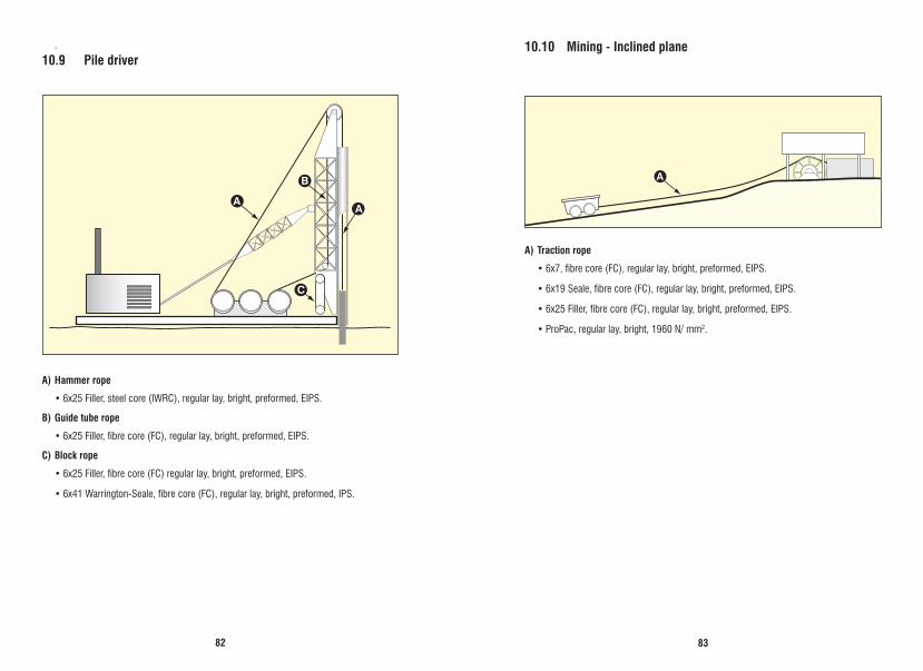
8382
10.10 Mining - Inclined plane
A) Traction rope
•6x7,fibrecore(FC),regularlay,bright,preformed,EIPS.
•6x19Seale,fibrecore(FC),regularlay,bright,preformed,EIPS.
•6x25Filler,fibrecore(FC),regularlay,bright,preformed,EIPS.
•ProPac,regularlay,bright,1960N/mm2.
.
10.9 Pile driver
A) Hammer rope
•6x25Filler,steelcore(IWRC),regularlay,bright,preformed,EIPS.
B) Guide tube rope
•6x25Filler,fibrecore(FC),regularlay,bright,preformed,EIPS.
C) Block rope
•6x25Filler,fibrecore(FC)regularlay,bright,preformed,EIPS.
•6x41Warrington-Seale,fibrecore(FC),regularlay,bright,preformed,IPS.
AA
B
C
A

8584
10.11 Mining - Inclined well
A) Hoisting rope
•6x19Seale,fibrecore(FC),regularlay,bright,preformed,EIPS.
•6x25Filler,fibrecore(FC),regularlay,bright,preformed,EIPS.
•ProPac,regularlay,bright,1960N/mm2
10.12 Vertical well
A) Hoisting rope
•6x25Filler,fibrecore(FC),regularlay,bright,preformed,EIPS.
Note:The following ropes are recommended in installations in which the cabin are not guided: Ergoflex or ErgoflexPlus
A) Track rope
•Full-lockedcoil
B) Tractor rope
•6x25Filler,fibrecorenatural,regularlay,bright,preformed,EIPS.
•6X19Seale,syntheticfibrecore(SFC),Langlay,bright,preformed,IPS.
Note: • Byvirtueofropewearonthebucketengagementbridges,itisrecommendedto
always choose the tractor rope with external wires as thick as possible, according to the diameters of the sheaves on the installation.
• Fordiametersbelow1inch,theconstruction6x25F+FC,regularlayandEIPSwireresistance can be used.
10.13 Cableway
A
A
A
A
A
B
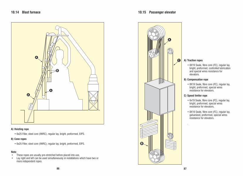
8786
10.14 Blast furnace
A) Hoisting rope
•6x25Filler,steelcore(IWRC),regularlay,bright,preformed,EIPS.
B) Cone ropes
•6x25Filler,steelcore(IWRC),regularlay,bright,preformed,EIPS.
Note: • Theseropesareusuallypre-stretchedbeforeplacedintouse,• Layrightandleftcanbeusedsimultaneouslyininstallationswhichhavetwoor
more independent ropes.
10.15 Passenger elevator
A) Traction ropes
•8X19Seale,fibrecore(FC),regularlay,bright, preformed, controlled lubrication and special wires resistance for elevators.
B) Compensation rope
•8X19Seale,fibrecore(FC),regularlay,bright, preformed, special wires resistance for elevators.
C) Speed limiter rope
•6x19Seale,fibrecore(FC),regularlay,bright, preformed, special wires resistance for elevators,
•8X19Seale,fibrecore(FC),regularlay,galvanized, preformed, special wires resistance for elevators.
.
A
A
A
B
A
C
B

8988
10.16 Work site winch - Work site elevator
A) Winch rope
•6x25Filler,steelcore(IWRC),regularlay,bright,preformed,EIPS,
•6x41Warrington-Seale,steelcore(IWRC),regularlay,bright,preformed,IPS.
Note: If the which drum has grooves, the wire rope can be used with fibre core (FC).
10.17 Percussion drilling
A) Drilling rope
•6x19Seale,fibrecore(FC),regularleftlay,bright,preformed,dualtensilewireresistance.
B) Auxiliary rope
•6x25Filler,fibrecore(FC),regularlay,bright,preformed,EIPS.
A
B
B B
A

9190
10.18 Rotary drilling
A) Drilling ropes
•6x19Seale,steelcore(IWRC),regularlay,bright,preformed,EIPS,
Note:Fibre core (FC) is recommended only in shallow wells.
B) Auxiliary ropes
•6x7,fibrecore(FC),regularlay,bright,preformed,IPSorEIPS.
10.19 Ropes for offshore
A) Anchoring rope
•6x25Filler,steelcore(IWRC),regularlay,preformed,galvanized,EIPS.
•6x36Warrington-Seale,steelcore(IWRC),regularlay,preformed,galvanized, EIPS/EEIPS.
•6x41Warrington-Seale,steelcore(IWRC),regularlay,preformed,galvanized, EIPS/EEIPS.
•6x47Warrington-Seale,steelcore(IWRC),regularlay,preformed,galvanized, EIPS/EEIPS.
B) Indicator rope
•6x25Filler,steelcore(IWRC),regularlay,preformed,galvanized,EIPS.
•6x36Warrington-Seale,steelcore(IWRC),regularlay,preformed,galvanized, EIPS/EEIPS.
•6x41Warrington-Seale,steelcore(IWRC),regularlay,preformed,galvanized, EIPS/EEIPS.
•6x47Warrington-Seale,steelcore(IWRC),regularlay,preformed,galvanized, EIPS/EEIPS.
Note: For other constructions, diameters and Minimum Breaking Force, consult our technical department.
A
B
AA
BB

9392
10.20 Rope for navy
A) Hoisting rope or halyard
•6x19Seale,fibrecore(FC),regularlay,preformed,galvanized,PS.
•6x25Filler,fibrecore(FC),regularlay,bright,preformed,IPS.
B) Cargo rope
•6x19Seale,fibrecore(FC),regularlay,preformed,galvanized,PS.
•6x41Warrington-Seale,fibrecore(FC),regularlay,galvanized,preformed,IPS.
•6x25Filler,fibrecore(FC),regularlay,bright,preformed,IPS.
C) Vangs
•6x7,fibrecore(FC),regularlay,galvanized,preformed,PS,
•6x19Seale,fibrecore(FC),regularlay,galvanized,preformed,PS
D) and E) Backstays
•6x7,fibrecore(FC),regularlay,galvanized,preformed,IPS.
•6x19Seale,fibrecore(FC),regularlay,galvanized,preformed,IPS.
•6x41Warrington-Seale,fibrecore(FC),regularlay,galvanized,preformed,IPS.
10.21 Ropes for fishing
A) Real rope
•6x7,fibrecore(FC),regularlay,galvanized,preformed,IPS.
•6x19Seale,syntheticfibrecore(SFC),regularlay,galvanized,preformed,IPS.
B) Scissors rope
•6x19Seale,syntheticfibrecore(SFC),regularlay,galvanizedpreformed,IPS.
A) Rope for net trawling
•6x19Seale,syntheticfibrecore(SFC),regularlay,galvanizedpreformed,IPS.
C
B D
A
E
AB
C
BA
A
AA
A
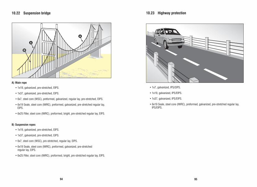
9594
10.22 Suspension bridge
A) Main rope
•1x19,galvanized,pre-stretched,EIPS.
•1x37,galvanized,pre-stretched,EIPS.
•6x7,steelcore(WSC),preformed,galvanized,regularlay,pre-stretched,EIPS.
•6x19Seale,steelcore(IWRC),preformed,galvanized,pre-stretchedregularlay,EIPS.
•6x25Filler,steelcore(IWRC),preformed,bright,pre-stretchedregularlay,EIPS.
B) Suspension ropes
•1x19,galvanized,pre-stretched,EIPS.
•1x37,galvanized,pre-stretched,EIPS.
•6x7,steelcore(WSC),pre-stretched,regularlay,EIPS.
•6x19Seale,steelcore(IWRC),preformed,galvanized,pre-stretched regular lay, EIPS.
•6x25Filler,steelcore(IWRC),preformed,bright,pre-stretchedregularlay,EIPS.
10.23 Highway protection
•1x7,galvanized,IPS/EIPS.
•1x19,galvanized,IPS/EIPS.
•1x37,galvanized,IPS/EIPS.
•6x19Seale,steelcore(IWRC),preformed,galvanized,pre-stretchedregularlay, IPS/EIPS.
A
A
B
A
A
B
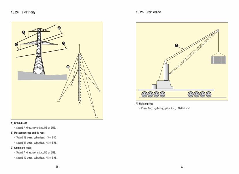
9796
10.24 Electricity
A) Ground rope
•Strand7wires,galvanized,HSorEHS.
B) Messenger rope and tie rods
•Strand19wires,galvanized,HSorEHS.
•Strand37wires,galvanized,HSorEHS.
C) Aluminum ropes
•Strand7wires,galvanized,HSorEHS.
•Strand19wires,galvanized,HSorEHS.
A) Hoisting rope
•PowerPac,regularlay,galvanized,1960N/mm2
10.25 Port crane
A
A
C
B
C A
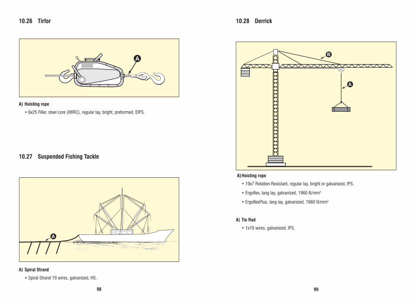
9998
10.27 Suspended Fishing Tackle
A) Spiral Strand
•SpiralStrand19wires,galvanized,HS.
10.26 Tirfor
A) Hoisting rope
•6x25Filler,steelcore(IWRC),regularlay,bright,preformed,EIPS.
10.28 Derrick
A) Hoisting rope
•19x7RotationResistant,regularlay,brightorgalvanized,IPS.
•Ergoflex,langlay,galvanized,1960N/mm2
•ErgoflexPlus,langlay,galvanized,1960N/mm2
A) Tie Rod
•1x19wires,galvanized,IPS.
A
AB
A
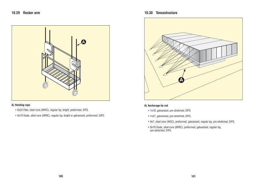
101100
10.29 Rocker arm
A) Hoisting rope
•6x25Filler,steelcore(IWRC),regularlay,bright,preformed,EIPS.
•6x19Seale,steelcore(IWRC),regularlay,brightorgalvanized,preformed,EIPS.
10.30 Tensostructure
A) Anchorage tie rod
•1x19,galvanized,pre-stretched,EIPS
•1x37,galvanized,pre-stretched,EIPS,
•6x7,steelcore(WSC),preformed,galvanized,regularlay,pre-stretched,EIPS,
•6x19Seale,steelcore(IWRC),preformed,galvanized,regularlay, pre-stretched, EIPS.
A
A

103102
10.31 Hillo Winch
A) Hoisting rope
•6x25Filler,fibrecore(FC)orsteelcore(IWRC),preformed,bright,pre-stretchedregular lay, EIPS.
•6x41Warrington-Seale,fibrecore(FC)orsteelcore(IWRC),regularlay,bright,preformed, IPS.
B) Slings
•6x25Filler,fibrecore(FC),preformed,bright,pre-stretchedregularlay,EIPS.
•This technical manual contains recommendations on the type of wire ropes to be used in the majority of industrial applications; however, we recommend that the wire rope to be replaced has similar characteristics to the original rope of the equipment or that our Technical Assistance is consulted to adapt the best product.
The Cimaf ropes are in constant development in their production, maintenance and distribution processes.
With the verticalization of the stockpiles, the Cimaf ropes have achieved a level of agility and organization which make the brand a pioneer in the development of
advanced logistic methods in its segment. A
B

105104
9A - 0014