Accessories for Web Slings, Round Slings and High Performance

Wire rope, rigging and Mooring For oFFshore ConstruCtionA Subsidiary of KTL Global Ltd


01
KTL Offshore Pte Ltd
CONTENTS
Introduction
Steel Wire Rope ForOffshore Construction
• AnchorWireAndWinchWire• WireRopeForPipeLayOperations• WireRopeForCranes
Heavy Lift Slings And Grommets
• KimSwageFlemishEyeSlings• KimFlexBraidedSlings• KimLockCableLaidSlings
–ResinSocketed• CableLaidSlings–HandSpliced• CableLaidGrommets• KimFlexBraidedGrommets• UltraShortGrommets• ApplicationInformation —HeavyLiftSlings• ApplicationInformation —HeavyLiftGrommets• Inspection,ExaminationAnd DiscardCriteria—HeavyLift SlingsAndGrommets• KimPlasmaGrommets
Heavy Lift Shackles
• CrosbyG-2160WideBodyShackles• CrosbyG-2140AlloyShackles• ApplicationInformation— HeavyLiftShackles
Mooring Systems And Deck Equipment
• Anchors• AnchorChainAndAccessories• Fairleaders,HorizontalAnd VerticalSheaves• OtherDeckEquipment
Towing Bridles
• ChafeChain• TowingStretchers• SpelterSockets• OtherTowingEquipment
Synthetic Slings And Grommets
• KimPlasmaEye-And-EyeSlingsAndGrommets
General Engineering Slings, Grommets And Shackles
Slings And Fittings For Offshore Containers
Rigging For Subsea Engineering
• RemoteOperatedVehicle(ROV) HooksAndShackles• ApplicationInformation—ROV HooksAndShackles• UmbilicalSpooling
Synthetic Ropes For Offshore Construction
• HMPERope-PlasmaAndSpectra• CompositeRopes,PolypropyleneAndNylon
Ropes
Blocks For Offshore Construction
• SnatchBlocks• HighWLL(HeavyDuty) SnatchBlocks• CraneBlocks,ConstructionBlocks AndSheaves• UnderwaterBlocks• RollForgedSheaves
Technical Services For The Offshore Industry
• Inspection,TestingAndCertification• WireRopeSpoolingAndInstallation• WireRopeLubrication• KIMTRACKInventoryManagementSystem
Our Partners
02
13
36
41
49
59
75
81
92
73
98
103
55
03

02
KTL Offshore Pte Ltd
With dedicated personnel and the world’s best brands along with one of the best quality systems in the industry, KTL Offshore has established a reputation for being a world class provider of rigging equipment and services. In addition, our new facility at Tuas in Singapore is one of the largest rigging facilities in the industry and is equipped with some of the biggest and best facilities available.
In this brochure, we highlight our products and services which are designed to solve problems encountered in the construction and installation industry.
KTL Offshore’s products and services at a glance:
• Over 6,000 metric tons of steel wire rope in stock (up to 6” diameter).
• The largest Crosby distributor outside the USA.
• Up to WLL 1550t Crosby Wide Body shackles in stock.
• The Kimtest 3000 tensile testing machine—one of the largest in the industry.
• Huge inventory of compacted crane wire rope brands from Europe.
• Manufacturer of heavy lift cable laid and braided slings (up to 24” in diameter) and grommets (up to 16” in diameter).
• Plasma high performance synthetic rope (HMPE)
• One of the most comprehensive product ranges in the rigging industry.
• Full range of technical services including spooling, testing, inspection and wire rope lubrication.
INTRODuCTION
KTL Offshore is proud to be a member of the following professional organizations:
At KTL Offshore we understand that the offshore construction and installation market is comprised of a group of customers who face a set of demands and challenges that are unique from everyone else. That is why we tailor our offer of products and services specifically to cater for this market segment.

03
KTL Offshore Pte Ltd
Rope Size ConstructionUp to 2” (50mm) 6x25 and 6x36
2” to 3” (50mm to 76mm) 6x36 and 6x41
3” to 3-1/2” (76mm to 90mm) 6x41, 6x47, 6x49 and 6x52
3-3/4” (96mm) and above 6x49, 6x52, 6x55 and 6x61
AHugeInventory
KTL Offshore maintains an inventory of over 6,000 metric tons of the world’s premium wire rope brands such as KISWIRE, usha Martin and DSR.
Tensile grades include EIPS and EEIPS as well as the latest ultra high-strength grades such as KISWIRE’s Alpha and Delta grades and Usha Martin’s Super Titan and Titan Max grades. These grades have a rated strength well in excess of the standard EEIPS grade.
WireRopeConstruction
Anchor and winch wire rope is subjected to heavy abrasion, fatigue, mechanical handling and corrosion damage. For all wire rope for offshore use we recommend a drawn galvanized surface finish. The zinc coating is applied prior to wire drawing and hence provides protection against corrosion while also retaining the required mechanical properties in the steel wire.
To achieve the optimum balance between fatigue and abrasion resistance, the following table provides a guide for the correct rope construction:
(Above and below) 90 metric ton reels of 3” diameter wire rope for the world’s largest Derrick Lay Barges, such as DB101 and Semac 1.Ordered by KTL Offshore to the latest international standards.
Certification
Our wire rope is ordered and supplied with mill and third party certification such as ABS, DNV and LR. The wire rope is manufactured in the largest and most sophisticated rope mills in the world to latest international standards such as the ANSI/API 9A (2004) and ISO 10425 (2003) combined specification.
WorldwideDelivery
KTL Offshore will arrange the transportation and necessary documentation to deliver wire ropes to virtually any location worldwide, with project management services included.
Our inventory includes wire rope for anchor line purposes from 1-1/2” (38mm) up to 6” (152mm) in diameter—one the most comprehensive ranges available in the world.
KTLOffshoreValueAddedService:
KTL Offshore operates a fleet of constant-tension spooling machines and a Technical Services Department that is dedicated to providing offshore services including installation of wire rope. We can install wire rope reels with an individual weight of up to 120 metric tons.
STEEL WIRE ROPE FOR OFFSHORE CONSTRuCTION Anchor Wire And Winch Wire

04
KTL Offshore Pte Ltd
(Left) 84mm diameter x 1,200 metres low rotation A&R wire rope supplied by KTL Offshore. The rope was manufactured by Redaelli in Italy.
Special Wire Rope For A&RApplications
Wire rope for A&R winches is fast evolving into a highly specialised product that only a few manufacturers can provide.
Depending upon water depth, the wire rope may be a standard construction, a low rotation type or rotation resistant type. At KTL Offshore, we can evaluate your operating conditions to recommend the correct type of wire rope. State-of-the-art CAD is used to conduct the evaluation, and recommendations are provided after consultation with our principles.
A standard 6x36 construction is very robust but has limited resistance to rotation and may cause complications because of twisting and eventual kinking of the wire rope. The 35xk7 low rotation rope has the best resistance to rotation and twisting. It is very rugged in the compacted form; as such, it is an excellent rope for use in A&R operations. The Spin 9KP rope has improved rotation resistance compared to the 6x36 type. Yet, it retains much of the abrasion resistance thanks to the nine compacted strands. It is a good option when the rope is for meant for dedicated use in A&R applications only.
Wire Rope For Shore PullApplications
When specified at the time of order, we are able to direct our wire rope manufacturer to design and supply steel reels that can handle the high back-tension forces exerted in a shore pull (beach pull) operation. As a value added service, we also engineer and modify existing steel reels to meet shore pull requirements.
6x36(Standard Rope)
Spin 9KP(Rotation Resistant)
35xk7(Low Rotation)
KTLOffshoreValueAddedServices:
• KTL Offshore can provide a Load vs Twist evaluation to demonstrate how the proposed wire rope will rotate and twist when loaded and lowered to a certain water depth.
• The steel reels supplied with the wire rope are critical, especially when used in beach pull operations. KTL Offshore can provide the strength and design calculations to assess strength and back-tension requirements, as well as modify and strengthen existing reels to meet the same criteria.
Wire Rope For Pipe Lay OperationsKTL Offshore Offers Years Of Experience In This Demanding Field

05
KTL Offshore Pte Ltd
Nominal DiameterApproximate
Weight Per Metre
Minimum Breaking Load (metric tons)
ANSI/API 9A/ISO 10425 Specification
KISWIREHigh Tensile Grades
USHA MARTINHigh Tensile Grades
(mm) (inches) (kg/m) (Ib/ft) EIPS EEIPS Alpha Delta Omega Super Titan Titan Max
CLASS 6x19 & 6x37 Steel Core
12.7 1/2 0.68 0.46 12.1 13.2
These grades are not available under 2” (52mm) diameter
16 5/8 1.07 0.72 18.7 20.6
19 3/4 1.55 1.04 26.7 29.4
22 7/8 2.11 1.42 36.1 39.7
26 1 2.75 1.85 46.9 51.6
28 1-1-/8 3.48 2.34 59 64.8
32 1-1/4 4.3 2.89 72.5 79.7
35 1-3/8 5.21 3.50 87.1 96.1
38 1-1/2 6.19 4.16 103 113.4
42 1-5/8 7.26 4.88 120 132.5
45 1-3/4 8.44 5.67 139 152.9
48 1-7/8 9.67 6.50 158 174.3
52 2 11.0 7.39 180 197 226 233 ** 227 **
54 2-1/8 12.4 8.35 200 221 241 252 ** 254 **
57 2-1/4 13.9 9.36 224 247 275 289 ** 281 **
60 2-3/8 15.5 10.4 249 274 298 312 ** 312 **
CLASS 6x37 Steel Core (API 9A - 1995)
64 2-1/2 17.3 11.6 274 301 336 353 ** 343 **
67 2-5/8 19.0 12.8 299 330 370 389 ** 376 **
70 2-3/4 20.8 14.0 333 360 409 429 448 410 448
73 2-7/8 22.8 15.3 361 392 447 469 490 447 490
76 3 24.7 16.6 389 425 491 516 538 484 538
79 3-1/8 26.8 18.0 417 458 522 548 572 522 572
83 3-1/4 29.0 19.5 447 493 557 585 611 562 611
86 3-3/8 31.3 21.0 487 528 607 637 666 602 666
89 3-1/2 33.8 22.7 519 563 659 692 723 642 723
95 3-3/4 38.7 26.0 585 640 714 750 785 717 785
102 4 44.0 29.6 665 720 796 836 ** 806 **
CLASS - Large Diameter Six Stranded Rope (ANSI/API 9A/ISO 10425 - August 2004)
102 4 44.0 29.6 646 796 836 ** 806 **
108 4-1/4 49.6 33.3 725 845 887 ** 910 **
114 4-1/2 55.7 37.4 805 939 986 ** 1004 **
121 4-3/4 62.1 41.7 890 1036 1088 ** ** **
127 5 68.8 46.2 978 1138 1195 ** 1196 **
133 5-1/4 74.1 49.8 1015 1184 1243 ** ** **
140 5-1/2 81.1 54.5 1101 1288 1352 ** ** **
146 5-3/4 88.7 59.6 1193 1396 1466 ** ** **
152 6 96.7 65.0 1294 1508 1583 ** ** **
Table Of Minimum Breaking Load (MBL) For Steel Wire RopeStandard 6-strand Wire Rope Construction: Bright (ungalvanised)
And Drawn Galvanised

06
KTL Offshore Pte Ltd
FLEXPACK 21
Diameter Minimum Breaking Force Mass
mm inch kN M.tons S.tons kg/m lbs/ft
90 6830 696 768 40.5 18.3
92 7100 723 798 42.3 19.2
3-5/8 7000 713 787 42.4 19.2
94 7380 752 830 44.2 20.0
3-3/4 7500 764 843 45.4 20.5
96 7660 780 861 46.1 20.9
98 7950 810 894 48.0 21.7
3-7/8 8000 815 900 48.4 21.9
100 8270 843 930 50.0 22.6
4 8500 866 956 51.6 23.4
102 8590 875 966 52.0 23.5
104 8920 909 1003 54.1 24.5
4-1/8 9000 917 1012 54.9 24.8
106 9250 942 1040 56.2 25.4
4-1/4 9500 968 1068 58.3 26.4
108 9590 977 1078 58.3 26.4
110 9940 1013 1118 60.5 27.4
4-3/8 10100 1020 1136 61.7 27.9
112 10200 1039 1147 62.7 28.4
114 10600 1080 1192 65.0 29.4
4-1/2 10700 1090 1203 65.3 29.6
116 11000 1121 1237 67.3 30.4
4-5/8 11200 1140 1260 69.0 31.2
118 11300 1151 1271 69.6 31.5
120 11700 1192 1316 72.0 32.6
4-3/4 11800 1200 1327 72.8 32.9
122 12100 1233 1361 74.4 33.7
4-7/8 12400 1260 1395 76.7 34.7
124 12500 1274 1406 76.9 34.8
126 12900 1314 1451 79.4 35.9
Diameter Minimum Breaking Force Mass
mm inch kN M.tons S.tons kg/m lbs/ft
5 13100 1330 1473 80.6 36.5
128 13300 1355 1496 81.9 37.1
130 13700 1396 1541 84.5 38.2
5-1/8 13700 1390 1541 84.7 38.3
132 14100 1437 1586 87.1 39.4
5-1/4 14400 1460 1620 88.9 40.2
134 14500 1478 1631 89.8 40.6
136 14900 1518 1676 92.5 41.9
5-3/8 15000 1520 1687 93.2 42.2
138 15300 1559 1721 95.2 43.1
5-1/2 15700 1600 1766 97.6 44.2
140 15800 1610 1777 98.0 44.3
142 16200 1651 1822 100.8 45.6
5-5/8 16400 1670 1845 102.1 46.2
144 16600 1692 1867 103.7 46.9
146 17100 1743 1923 106.6 48.2
5-3/4 17100 1740 1923 106.7 48.3
148 17500 1783 1968 109.5 49.6
5-7/8 17800 1810 2002 111.3 50.4
150 18000 1834 2025 112.5 50.9
152 18500 1885 2081 115.5 52.3
6 18500 1880 2081 116.1 52.6
154 18900 1926 2126 118.6 53.7
6-1/4 19300 1960 2171 121.0 54.8
156 19400 1977 2182 121.7 55.1
158 19900 2028 2239 124.8 56.5
6-1/4 20100 2040 2261 126.0 57.0
160 20400 2079 2295 128.0 57.9
6-3/8 20800 2120 2340 131.1 59.3
162 20800 2120 2340 131.2 59.4

07
KTL Offshore Pte Ltd
*Comparison Of Physical Properties Of Flexpack And Standard Wire Rope
Type of Rope Cross Section Modulus of Elasticity (kN/mm2)
Torque Factor (at 20% of Rope MBL)
Rotation Factor (degrees/1000.d.MPa)
FLEXPACK (35xk7) 130 0.025 0.20
6x36+lWRC 110 0.078 24
*Note: These factors are non-linear and may vary with rope MBL and diameter.For an accurate calculation of rope twist vs load for any particular application, please contact KTL Offshore.
FLEXPACK is the registered trademark of Redaelli Tecnacordati (Italy), one of KTL Offshore’s principle manufacturers.
Redaelli Steel Wire Rope – manufacturing low rotation wire rope with an individual reel weight of up to 500 metric Tons – the heaviest rope in the world!

08
KTL Offshore Pte Ltd
The latest concept in heavy lift cranes for offshore operations is the Heavy Lift Mast Crane. Popular brands include Huisman, Seatracks and Amclyde.
These cranes use the latest in wire rope designs to achieve the high breaking load and safety factors of the upgraded API 8C specification.
The modern HLM crane demands wire rope having extremely tight tolerances on specification – it is very important that careful consideration is given to the correct rope construction and brand before selecting the replacement wire rope. KTL Offshore recommends only Redaelli (Italy) for HLM crane applications.
KTL Offshore maintains an impressive inventory of these two brands of wire rope.
Main, Auxiliary And Whip (Fly)HoistWireRope
Depending upon crane design, wire rope for main, auxiliary and whip (fly) hoist duty may either be a low rotation or non-rotation resistant construction. When a double drum hoisting system is deployed, a left hand and right hand non-rotation resistant combination is usually used. For single drum applications, a low rotation wire rope is often recommended by the crane designer. Consult KTL Offshore for the correct selection of wire rope.
BoomHoist(Luffing)AndToppingWireRope
Compacted 8- or 9-strand wire rope with plastic impregnation is the ideal choice for demanding boom hoist (luffing) and topping applications. Double-parallel closed wire ropes are also used as they exhibit superior fatigue life and exceptionally high breaking loads.
A compact 35xk7 low rotation wire rope is the ideal choice for single-drum hoisting applications. Most HLM cranes use this type for the main and auxiliary hoist ropes.
For paired rope systems, robust non-rotation resistant types such as the 8- or 9-strand compacted wire rope with plastic impregnation are more suitable.
Redaelli’s Pack 9P offers increased fatigue life due to the 9 compacted outer strands. In addition, the plastic impregnation offers greater crushing, fatigue and shock loading ability.
Wire Rope For CranesHeavy Lift Mast (HLM) Cranes

09
KTL Offshore Pte Ltd
Most derrick crane barges use the older, standard wire rope designs for crane applications. However, many operators are now replacing these designs with high performance wire rope such as compacted 6- and 8-strand, and compacted 35xK7 low rotation wire rope.
This is because the extreme crushing forces exerted on the boom rope in particular under conditions of multilayer coiling. Compacted 6-strand wire rope is very robust. Trials by one of the world’s largest offshore construction and derrick crane barge operators have proven that the use of high performance wire rope greatly extends the rope life.
The standard 6x25Fi construction (left) may be replaced by the compact 6x36 type (right) for increased rope performance.
OffshorePedestalCranes
Pedestal cranes have a very high work ratio as they are most commonly used on offshore drilling rigs and small to medium derrick barges. As this application is extremely demanding, only wire rope of the highest quality is suitable.
Compact 35xK7: ideal for main, auxiliary and whip (fly) hoisting and pendant rope applications.
Compact 6x36: highly rugged construction that is suitable for boom (luffing) hoist duties.
Compact 8-strand with plastic impregnation: 8 strands and plastic layer increase fatigue, crushing and shock absorbing ability. It is ideal for boom (luffing)hoist duties.
Compact 9-strand with plastic impregnation: added fatigue and crushing resistance makes it the ultimate rope for boom (luffing) applications.

10
KTL Offshore Pte Ltd
DavitWireRope
The davit is used to raise and lower equipment over the side of the vessel, sometimes in significant water depths. The reeving system is usually very simple, therefore for these reasons it is recommended to use standard or compacted 6-strand wire rope.
DiveSupportVessel(DSV)CraneRope
The Dive Support Vessel (DSV) has unique requirements for wire rope used in the bell hoist application. At KTL Offshore our personnel understand these requirements and we are able to provide the additional value added services to ensure your operation runs trouble-free and safely.
KTLOffshoreValueAddedServices:
• We have qualified wire rope inspectors to carry out visual, non-destructive and destructive testing for bell wire.
• Destruction testing of bell wire requires special sample preparation as well as the right testing conditions for reliable and accurate test results. Our wire rope inspectors are highly trained in this area.

11
KTL Offshore Pte Ltd
Mobile,Lattice,Container,TowerAndOtherCranes
Our inventory and expertise span the broad spectrum of the crane market. Beyond large offshore heavy lift cranes, we also supply general cranes and we have a solution for every type of crane.
CompactedVSStandardWireRope:
The use of compacted wire rope will significantly increase the rope life.

12
KTL Offshore Pte Ltd
Special Crane Ropes Multistrand Hi-Tech Crane Ropes Non Rotating Hi-Tech Crane Ropes
Pack1 Pack1P Pack9 Pack9P Flexpack Flexlpast
(mm) Mass MBF Mass MBF Mass MBF Mass MBF Mass MBF Mass MBF
kg/m 1960kN
2160kN kg/m 1960
kN2160kN kg/m 1960
kN2160kN kg/m 1960
kN2160kN kg/m 1960
kN2160kN kg/m 1960
kN2160kN
678 0.30 57.6 62.79 0.38 72.9 79.410 0.45 85 91 0.46 85 91 0.47 90 98 0.47 90 98 0.48 92 98 0.49 92 9811 0.55 103 110 0.56 103 110 0.57 109 119 0.57 109 119 0.58 111 119 0.59 111 11912 0.65 122 131 0.66 122 131 0.68 130 141 0.68 130 141 0.69 132 141 0.70 132 14113 0.76 144 154 0.78 144 154 0.80 152 166 0.80 152 166 0.81 155 166 0.82 155 16614 0.89 167 178 0.90 167 178 0.93 176 192 0.92 176 192 0.94 180 192 0.95 180 19215 1.02 191 205 1.03 191 205 1.06 203 221 1.06 203 221 1.08 207 221 1.09 207 22116 1.14 218 233 1.18 218 233 1.25 230 251 1.22 230 251 1.27 136 251 1.26 236 25117 1.28 246 263 1.33 246 263 1.41 260 283 1.38 260 283 1.43 266 283 1.43 266 28318 1.44 275 295 1.49 275 295 1.58 292 318 1.54 292 318 1.61 298 318 1.60 298 31819 1.60 307 329 1.66 307 329 1.76 325 354 1.72 325 354 1.79 332 354 1.78 332 35420 1.78 340 364 1.84 340 364 1.95 360 392 1.90 360 392 1.98 368 392 1.98 368 39222 2.15 411 440 2.22 411 440 2.36 436 474 2.30 436 474 2.40 445 474 2.39 445 47424 2.56 490 524 2.64 490 524 2.81 518 564 2.74 518 564 2.86 530 564 2.85 530 56426 3.03 561 602 3.10 575 615 3.29 608 662 3.22 608 662 3.35 608 649 3.34 608 64928 3.51 651 698 3.60 651 713 3.82 690 753 3.73 690 753 3.86 706 753 3.87 706 75330 4.03 747 801 4.13 747 801 4.38 792 864 4.28 792 864 4.46 810 864 4.45 810 86432 4.59 850 911 4.70 850 911 4.99 901 983 4.87 901 983 5.08 922 983 5.06 922 983
34 5.18 959 1030 5.31 959 1030 5.63 1020 1110 5.50 1020 1110 5.73 1040 1110 5.71 1040 1110
36 5.81 1080 1150 6.04 1080 1150 6.31 1140 1240 6.17 1140 1240 6.43 1170 1240 6.40 1170 1240
38 6.47 1200 1290 6.73 1200 1290 7.03 1270 1390 6.87 1270 1390 7.16 1300 1390 7.13 1300 1390
40 7.17 1330 1420 7.46 1330 1420 7.79 1410 1540 7.62 1410 1540 7.94 1440 1540 7.90 1440 1540
42 7.94 1430 1530 8.22 1430 1530 8.59 1520 1660 8.40 1520 1660 8.82 1550 1660 8.71 1550 1660
44 8.71 1570 1680 9.02 1570 1680 9.43 1660 1820 9.22 1660 1820 9.68 1700 1820 9.56 1700 1820
46 9.52 1710 1840 9.86 1710 1840 10.3 1820 1990 10.1 1820 1990 10.6 1860 1990 10.5 1860 1990
48 10.4 1870 2000 10.7 1870 2000 11.2 1980 2170 11.0 1980 2170 11.5 2030 2170 11.4 2030 2170
50 11.3 2030 2180 11.7 2030 2180 11.6 2150 2350 12.2 2150 2350 12.5 2200 2350 12.4 2200 2350
52 12.2 2190 2350 12.6 2190 2350 12.6 2330 2540 13.1 2330 2540 13.5 2330 2490 13.4 2330 2490
54 13.1 2360 2540 13.6 2360 2540 13.6 2510 2740 14.2 2510 2740 14.6 2510 2680 14.4 2510 2680
56 14.1 2540 2730 14.6 2540 2730 14.6 2700 2950 15.2 2700 2950 15.7 2700 2890 15.5 2700 2890
58 15.1 2720 2930 15.7 2720 2930 15.6 2890 3160 16.3 2890 3160 16.8 2890 3090 16.6 2890 3090
60 16.2 2920 3130 16.8 2920 3130 16.7 3100 3380 17.5 3100 3380 18.0 3100 3310 17.8 3100 3310
Redaelli High Performance Crane Rope
13
KTL Offshore Pte Ltd
HEAvy LIFT SLINGS AND GROMMETSEngineering the World’s Biggest and Best Heavy Lift Slings and Grommets
A Proven Track Record InTheHeavyLiftIndustry...
Some of our more prestigious and recent projects include the following:
• ESSO – Australia (2010)
• Mumbai High North – India (2010)
• Iwaki – Japan (2010)
• Saudi Aramco LTA – Saudi Arabia (2010)
• Morogot – Thailand (2009)
• Mumbai High South – India (2008)
• Reliance – India (2008)
• Manifa –Saudi Arabia (2007)
• Aramco – Saudi Arabia (2007)
• Kerisi – Indonesia (2007)
• Qatar Gas – Qatar (2007)
• Sarawak SSB – Malaysia (2007)
• BP Tan Lay – Vietnam (2007)
• Kupe Gas – New Zealand (2007)
• Huisman crane testing – Singapore (2006)
• Jasmine B – Thailand (2006)
• Qatar Gas – Qatar (2006)
• Bongkot – Thailand (2005)
• Ruby Second Phase – Vietnam (2005)
• Nine Wells Second Phase – India (2005)
• Ruby First Phase – Vietnam (2005)
• Sakhalin – Russia (2005)
• Dolphin – Saudi Arabia (2005)
• Otway Gas – Australia (2005)
• Apache John Brooks – Australia (2004)

14
KTL Offshore Pte Ltd
KTL Offshore’s Heavy Lift Slings:Quality, Reliability and Accuracy
AnUnswervingCommitmenttoQuality...
Manufactured at our facility in Singapore, our slings and grommets are made with the following characteristics:
• Engineered Length Control (ELC)
All slings and grommets are engineered to attain the required effective length at the specified working load.
• Consistency and Quality Of Workmanship
Each sling and grommet is produced in accordance to a dedicated Quality Control Plan that controls specification, tolerance and fabrication parameters.
• Tested With Third Party Certification
Every sling and grommet is proof load tested after manufacture to ensure the sling or grommet meets specification. A consolidated certificate and Load-Extension graph is provided with every sling and grommet.
KTL Offshore - manufacturer ofqualityheavyliftslingsandgrommetsbackedbyyearsofexperience.

15
KTL Offshore Pte Ltd
Heavy Lift Sling Product Range (Steel Wire Rope)
KimSwageFlemishEyeSlings
KimSwage slings are large diameter wire rope slings using a single wire rope with a Flemish eye splice. This new product range eliminates the need to use a braided or cable laid sling for the lower range of heavy lift slings.
The KimSwage range has outstanding flexibility and ease of handling that is similar to a single wire rope. The range is available in 4-1/2” (114mm), 5.0” (127mm) and 6.0” (152mm) diameters. The 6.0” diameter sling is made from an 8-strand wire rope for increased flexibility.
The KimSwage range is made to the same strict tolerances as our KimFlex and cable laid slings.
KimFlexBraidedSlings
KimFlex braided slings are multi part slings braided in a 9-strand configuration and terminated using a Flemish eye splice and steel ferrules. This produces heavy lift slings that are extremely easy to handle.
The typical construction of a KimFlex sling is 9x(6x36+IWRC).
The eyes are laid in parallel to produce a very narrow structure, making these slings ideal for situations where there are limited spaces for the connection at the eye.
Available in diameters up to 24”, KimFlex braided slings offer the following advantages:
• Flexibility
• Ease of inspection
• ‘Narrow Gap’ eye dimension
• Reduced weight
• Reduced rotation properties
KimLockCableLaidSlings–ResinSocketed
The KIMLOCK cable laid sling has a resin socketed termination with an efficiency of 100%. This results in a sling with a very high breaking force.
KTL Offshore designs and fabricates our KIMLOCK cable laid slings to the PM20 (1987) Guidance Note. The typical construction of a KIMLOCK cable laid sling is 7x(6x36+IWRC).
KIMLOCK cable laid slings are available up to 16” in diameter.

16
KTL Offshore Pte Ltd
CableLaidSlings–HandSpliced
Hand spliced cable laid slings have been used in the offshore industry for several decades and are still a favorite with many heavy lift contractors due to their proven ruggedness and reliability.
KTL Offshore designs and fabricates our cable laid slings to the IMCA M179 (2004) specification, which replaces the old PM 20 series.
The typical construction of a cable laid sling is 7x(6x36+IWRC).
Cable laid slings are available up to 16” in diameter.
Heavy Lift Grommet Product Range (Steel Wire Rope)
CableLaidGrommets
Made to IMCA M179 (2004), cable laid grommets offer an extremely rugged lifting connection that is able to withstand the most adverse bending and lifting conditions.
Laid up with six outer ropes over a core rope, the core rope is butted and not spliced and hence it is disregarded in the strength calculation and the construction of a cable laid grommet is depicted as 12x(6x36+IWRC). This is in compliance to IMCA M179 as well as the now withdrawn PM 20 specification.
KTL Offshore cable laid grommets are provided with 3-ply wire rope seizing at each end, steel identification collar and visibly marked tuck and core butt positions.
Cable laid grommets are available up to 13.5” in diameter.
KTLOffshorecablelaidgrommetsareproduced“TwistFree”toensureeaseofuse.

17
KTL Offshore Pte Ltd
UltraShortGrommets
The Ultra Short grommet has been designed in response to the requirement of many engineers for a heavy lift connection where the head room is extremely limited.
The Ultra Short grommet provides the big connection where the space and available lifting height is severely constrained.
KimFlexBraidedGrommets
KimFlex braided grommets are multi part grommets braided in a 9-strand configuration in two parts.
These grommets offer excellent handling characteristics.
The typical construction of a KIMFLEX grommet is 18x(6x36+IWRC).
KTL Offshore has developed our unique Crush Buster, a device which is manufactured and incorporated at each end of the grommet to reduces crushing and distortion of the grommet at the bearing contact points during lifting. Independent testing under ABS witness has proven the effectiveness of this device in reducing damage to the grommet.
KimFlex grommet are available up to 16.2” in diameters.
KTLOffshoreKIMFLEXgrommetsareproduced“TwistFree”toensureeaseofuse.
KTLOffshoreULTRASHORTgrommetsareproduced“TwistFree”toensureeaseofuse.

18
KTL Offshore Pte Ltd
Application Information—Heavy Lift Slings
1.WhichHeavyLiftSlingToUse?
The answer to this question depends upon several factors, mainly concerned with the type of lift being planned.
Where the required working load permits, the single-part KimSwage Flemish eye slings should always be used as they have the highest strength-to-mass ratio and are the easiest slings to handle.
When the working load exceeds the maximum available in the KimSwage range, the choice is between the flexible KimFlex range and the robust cable laid range. While each sling type posses certain advantages over the other, either type can be used safely for almost any lift. The table below provides a guideline for the optimum sling selection.
*Refers to the ANSI/API 9A/ISO 10425 Classification for wire rope constructions. Strength-to-mass ratio is the CSBL divided by the total mass of a 20-metre long sling at the maximum available diameter.CSBL is the term used to denote sling strength for slings made from multiple component wire rope while MBL is used for slings made from a single component wire rope.#Sling should be de-rated by 20% when used with a swivel.
2.DesignFactor,SafetyFactorAndRatedCapacity(WLLorSWL)
In keeping with good practice and sound engineering design KTL Offshore follows the recommended practice as stipulated in the major international specifications such as IMCA M179 and ASME B30.9. The Wire Rope Sling Users Manual issued by the Wire Rope Technical Board is also a widely respected reference document.
The design factor or safety factor is used to calculate the sling or grommet’s rated capacity and allows for conditions such as wear, abrasion, damage and variations in load.
The rated capacity of a sling or grommet is based upon the minimum breaking load of the component wire rope, splicing efficiency, spinning loss, number of parts of wire rope used, type of hitch, diameter around which the body of the sling or grommet is bent (D/d) and the diameter of the pin used in the eye of the sling.
In the industry many terms are used to describe the rated capacity such as Working Load Limit (WLL) and Safe Working Load (SWL). In line with IMCA M179 and PM 20, KTL Offshore uses the term WLL to designate the maximum allowable load the sling or grommet is allowed to raise, lower or suspend.
ApplicationTableForHeavyLiftSlings
*Sling Type & Body
Configuration
Max. Size and CSBL or MBL
Strength-to-Mass Ratio
FlexibilityAbrasion
Resistance
Crush Resistance/
Suitability for Use in Basket Hitch
Shock Load Resistance
Torsion/ Twist Resistance
Use with a Swivel
KIMSWAGE
6x36 & 8x36
6” diameter
(152mm)
1,425 MT
353 Medium High High High Low No
KIMFLEX
9x(6x36)
24” diameter
(608mm)
11,390 MT
347 High Medium Medium Medium Medium Yes#
CABLE LAID (Hand Spliced)
7x(6x36)
16” diameter
(406mm)
4,488 MT
173 Low High High Low Low No
KIMLOCK CABLE LAID
(Resin Socketed)
7x(6x37)
16” dia
(406mm)
7,063 MT
367 Medium High High Medium Low No
KTL Offshore Offers The Widest Choice For Your Heavy Lift Requirements

19
KTL Offshore Pte Ltd
2.1WLLForKimSwageSlings
For a straight pull with no horizontal angle, the rated capacity for KimSwage slings is provided by the following formula:
Where:
MBL = Minimum Breaking Load of KimSwage sling using a splicing efficiency of 0.9
Minimum D/d at the eye = 1.0WLL = MBL Safety Factor
2.2WLLForKimFlexSlings
For a straight pull with no horizontal angle, the rated capacity for KimFlex slings is provided by the following formula:
WLL = CSBL Safety Factor
Where:
CSBL = Calculated Sling Breaking Load of KimFlex sling
Minimum D/d at the eye = 0.75
2.3WLLForCableLaidSlings(HandSpliced)
For a straight pull with no horizontal angle, the rated capacity for cable laid slings is provided by the following formula:
WLL = CSBL Safety Factor
Where:
CSBL = Calculated Sling Breaking Load according to IMCA M179 and PM 20
CSBL = CRBL x 0.75 for hand spliced slings
CRBL = Calculated Rope Breaking Load
IMCA M179 and PM20 recommend a minimum safety factor of 2.25
Minimum D/d at the eye = 1.0
2.4WLLForKimLockCableLaidSlings(ResinSocketed)
For a straight pull with no horizontal angle, the Rated Capacity for KIMLOCK cable laid slings is provide by the following formula:
WLL = CSBL Safety Factor
Where:
CSBL = Calculated Sling Breaking Load according to PM 20
CSBL = CRBL x 1.00 for resin socketed slings
CRBL = Calculated Rope Breaking Load
IMCA M179 and PM20 recommend a minimum safety factor of 2.25
Minimum D/d at the eye = 1.0
20
KTL Offshore Pte Ltd
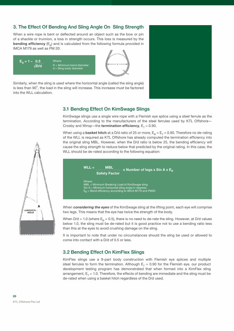
3.TheEffectOfBendingAndSlingAngleOnSlingStrength
When a wire rope is bent or deflected around an object such as the bow or pin of a shackle or trunnion, a loss in strength occurs. This loss is measured by the bending efficiency (EB) and is calculated from the following formula provided in IMCA M179 as well as PM 20:
Similarly, when the sling is used where the horizontal angle (called the sling angle) is less than 90o, the load in the sling will increase. This increase must be factored into the WLL calculation.
EB = 1 – 0.5 √D/d
3.1BendingEffectOnKimSwageSlings
KimSwage slings use a single wire rope with a Flemish eye splice using a steel ferrule as the termination. According to the manufacturers of the steel ferrules used by KTL Offshore—Crosby and Wirop—the termination efficiency, ET = 0.90.
When using a basket hitch at a D/d ratio of 25 or more, EB = ET = 0.90. Therefore no de-rating of the WLL is required as KTL Offshore has already computed the termination efficiency into the original sling MBL. However, when the D/d ratio is below 25, the bending efficiency will cause the sling strength to reduce below that predicted by the original rating. In this case, the WLL should be de-rated according to the following equation:
When considering the eyes of the KimSwage sling at the lifting point, each eye will comprise two legs. This means that the eye has twice the strength of the body.
When D/d = 1.0 (where EB = 0.5), there is no need to de-rate the sling. However, at D/d values below 1.0, the sling must be de-rated but it is good practice not to use a bending ratio less than this at the eyes to avoid crushing damage on the sling.
It is important to note that under no circumstances should the sling be used or allowed to come into contact with a D/d of 0.5 or less.
Where:
D = Minimum bend diameterd = Sling body diameter
3.2BendingEffectOnKimFlexSlings
KimFlex slings use a 9-part body construction with Flemish eye splices and multiple steel ferrules to form the termination. Although ET = 0.90 for the Flemish eye, our product development testing program has demonstrated that when formed into a KimFlex sling arrangement, ET = 1.0. Therefore, the effects of bending are immediate and the sling must be de-rated when using a basket hitch regardless of the D/d used.
WLL = MBL
Safety Factor
Where:MBL = Minimum Breaking Load of KimSwage slingSin A = Minimum horizontal sling angle in degreesEB = Bend efficiency according to IMCA M179 and PM20
x Number of legs x Sin A x EB
21
KTL Offshore Pte Ltd
When using a basket hitch all KimFlex slings should be de-rated according to the following calculation:
When considering the eyes of the KimFlex sling at the lifting point, each eye is comprised of 12-parts of wire rope laid in parallel. Because of this arrangement, at D/d = 0.75 or greater, there is no need to de-rate the sling. However, at D/d values below 0.75, the sling must be de-rated but it is good practice not to use a bending ratio less than this at the eyes to avoid crushing damage on the sling.
It is important to note that under no circumstances should the sling be used or allowed to come into contact with a D/d of 0.5 or less.
WLL = CSBL Safety Factor
Where:CSBL = Calculated Sling Breaking Load of KimFlex slingSin A = Minimum horizontal sling angle in degreesEB = Bend efficiency according to IMCA M179 and PM20
3.3BendingEffectOnCableLaidSlings–HandSpliced
Hand spliced cable laid slings use a 7-part body construction with hand splicing to form the termination. According to IMCA M179 and PM 20, for hand spliced cable laid slings ET = 0.75.
IMCA M179 and PM 20 stipulate the following guidelines when considering the effects of bending on cable laid slings:
For hand spliced slings only, when using a basket hitch at a D/d ratio of 4 EB = ET = 0.75 therefore no de-rating of the WLL is required as the termination efficiency of 0.75 has already been factored into the original sling CSBL. EB and ET are not additive therefore whichever one causes the greater loss in strength is used to calculate the sling strength. As the D/d ratio drops to below 4 the bending efficiency EB is less than the termination efficiency ET and the WLL should be de-rated according to the following equation:
For resin socketed cable laid slings, since ET = 1.0 the effects of bending are immediate and the sling must be de-rated using the equation above regardless of the D/d used.
When considering the eyes of the cable laid sling at the lifting point, each eye will comprise two legs. This means that the eye has twice the strength of the body.
When D/d = 1.0 (where EB = 0.5), there is no need to de-rate the sling. However, at D/d values below 1.0, the sling must be de-rated but it is good practice not to use a D/d less than 1.0 at the eyes to avoid crushing damage on the sling.
Both IMCA M179 and PM 20 stipulate that under no circumstances should the cable laid sling be used or allowed to come into contact with a D/d of 0.5 or less.
x Number of legs x Sin A x EB
WLL = CRBL Safety Factor
For hand spliced slings where D/d is equal to or greater than 4, replace EB with ET = 0.75
For resin socketed slings, EB is used regardless of D/d
IMCA M179 and PM20 recommend a minimum safety factor of 2.25
Where:
CRBL = Calculated Rope Breaking Load according to IMCA M179 and PM 20
Sin A = Minimum horizontal sling angle in degrees
EB = Bend efficiency according to IMCA M179 and PM20
x Number of legs x Sin A x EB
22
KTL Offshore Pte Ltd
3.4BendingEffectOnKimLockCableLaidSlings–ResinSocketed
KIMLOCK cable laid slings use a 7-part body construction with either hand splicing or a resin socket to form the termination. According to PM 20 for resin socketed slings ET = 1.0.
IMCA M179 and PM 20 stipulate the following guidelines for considering the effects of bending on cable laid slings:
For resin socketed cable laid slings, since ET = 1.0 the effects of bending are immediate and the sling must be de-rated using the below equation regardless of the D/d used.
When considering the eyes of the KIMLOCK cable laid sling at the lifting point, each eye is comprised of two legs therefore providing twice the strength as the body of the sling. Thus at a D/d = 1.0 where EB = 0.5, there is no need to de-rate the sling. At values below 1.0, the sling must be de-rated but it is good practice not to use a D/d less than 1.0 at the eyes to avoid crushing damage on the sling.
IMCA M179 and PM 20 both stipulate that under no circumstances should the cable laid sling be used with a D/d of 0.5 or less.
WLL = CSBL Safety Factor
For KIMLOCK resin socketed slings EB is used regardless of D/d
IMCA M179 and PM20 recommend a minimum safety factor of 2.25
Where:
CSBL = Calculated Rope Breaking Load according to IMCA M179 and PM 20
Sin A = Minimum horizontal sling angle in degrees
EB = Bend efficiency according to IMCA M179 and PM20
x Number of legs x Sin A x EB

23
KTL Offshore Pte Ltd
4.SlingRotationAndTheUseOfSwivels
When any type of steel wire rope sling is loaded, torque will develop in the sling body. This build up of torque may cause the sling and the load being lifted to rotate under certain circumstances.
KimFlex slings have the best resistance to rotation because they are manufactured in a braided manner. The braided construction affords some inherent resistance to rotation, although these slings are not to be considered as non-rotating.
Independent testing by KTL Offshore has demonstrated that it is possible to use KimFlex slings with a swivel to relieve some of the torque build up in the sling construction. However, the WLL of the sling should be reduced to take into account the effects of twisting of the sling body on the strength of the sling.
The following twist data may be used as a guide for KimFlex slings:
Cable laid and KimSwage slings are made in either a left hand or right hand direction of lay and have no inherent resistance to rotation. As the sling is loaded, the wire rope will turn in the opposite direction of lay and may eventually cause twist.
CABLE LAID (hand spliced and KIMLOCK) and KIMSWAGE slings should not be used with a swivel as this may cause the sling to unlay leading to catastrophic failure.
*The above data applies only to KimFlex slings manufactured by KTL Offshore and tested using a Crosby swivel. Braided slings and swivels made by other manufacturers have different manufacturing parameters and design characteristics which may result in different twist behaviour.
5.SlingsAndTheUseOfACrushBuster
KTL Offshore has developed the unique Crush Buster device. The Crush Buster has the ability to absorb a certain amount of crushing energy that is generated at the contact point between the sling and connection when a load is lifted.
Crush Busters (left) are recommended for all KimFlex slings used for basket hitch lifts. In addition, KTL Offshore supplies all KimFlex grommets as standard with a Crush Buster at each end. Independent testing and verification by ABS Consulting has proven the effectiveness of the Crush Buster device in reducing the effects of crushing on the sling/grommet body. Crush Busters are not available for cable laid slings or grommets. The 3-ply wire rope seizing is recommended for these products.
TwistDataForKimFlexSlings*
Recommendation/Guideline Data
Load at which Swivel may First Rotate 3% to 5% of CSBL
Reduction in WLL Requiredwhen using a Swivel
20%

24
KTL Offshore Pte Ltd
Application Information—Heavy Lift Grommets
1.WhichHeavyLiftGrommetIsSuitable?
As for slings, the answer to this question depends on several factors like the type of lifting project or simply user preference.
We recommend the flexible KimFlex range and the robust cable laid range. While each grommet type has certain advantages over the other, both can be used safely for almost any lift. The Ultra Short grommet is designed specifically for situations where the lifting height is restricted. The table below provides a guide for the optimum grommet selection.
ApplicationTableForHeavyLiftGrommets
*6x36 refers to the ANSI/API 9A/ISO 10425 Classification for wire rope constructions. Strength-to-mass ratio is the CGBL divided by the total mass of a 20 metre long grommet.
2. The Effect Of Bending AndHorizontal Angle On GrommetStrength
Since the strength of a grommet is calculated according to the body in double part, the effects of bending must considered regardless of the D/d (unlike for slings where the eye has more strength than the body and hence is able to connect at a very low D/d ratio without a reduction in WLL).
IMCA M179 and PM 20 describe the effects of bending on the grommet strength. After thorough evaluation through our own product development program, KTL Offshore recommends that these guidelines are followed for both KimFlex and cable laid grommets.
For grommets, if the horizontal angle (sling angle) is less than 90°, the load in the grommet will be increased and must be factored into the WLL calculation.
Grommet
Type & Body
Configuration*
Max. Size
and CGBL
Strength-to
-Mass RatioFlexibility
Abrasion
Resistance
Crush
Resistance
Shock Load
Resistance
Torsion/ Twist
Resistance Body Profile
KIMFLEX
18x(6x36)
16.2”
(412mm)
10,368 MT
499 High Medium Medium Medium Medium Braided
ULTRA
SHORT
36x(6x36)
26.1”
(664mm)
10,460 MT
N/A Low Medium Medium Medium High Braided
CABLE LAID
12x(6x36)
13.5”
(342mm)
8,066 MT
494 Medium High High Medium Low Smooth

25
KTL Offshore Pte Ltd
2.1BendingEffectOnKimFlexAndCableLaidGrommets
According to IMCA M179 and PM20, the effect of bending must be factored into the WLL calculation for all cable laid grommets. In addition KTL Offshore applies this rule to KiMFlex grommets as well.
The following equation is used to determine the WLL for both types of grommets:
When the horizontal angle is less than 90o, the following formula should be used to determine the WLL:
2.2BendingEffectOnUltraShortGrommets
Ultra short grommets are designed and rated based on a minimum D/d ratio of 5:1.
For smaller D/d ratios, use the following formula to estimate the WLL:
WLL = CGBL x EB
Safety Factor
Where:CGBL = Calculated Grommet Breaking LoadEB = Bend efficiency according to IMCA M179 and PM20IMCA M179 and PM20 recommend a minimum safety factor of 2.25 for cable laid grommets
WLL = CGBL
Safety Factor
Where:CGBL = Calculated Grommet Breaking LoadEB = Bend efficiency according to IMCA M179 and PM20Sin A = Minimum horizontal sling angle in degreesIMCA M179 and PM20 recommend a minimum safety factor of 2.25 for cable laid grommets
x Sin A x EB
WLL = CGBL x EB
Safety Factor
Where EB = 1 – 0.5
√8.D/d
Bending Dia to Grommet Dia (D/d ratio)
Ben
din
g E
ffici
ency
EB
0.70
1.00
0.85
0.75
0.90
0.80
0.95
0 0.5 1 1.5 2 3 42.5 3.5 4.5 5
Bending Efficiency for Ultra Short Grommets

26
KTL Offshore Pte Ltd
Inspection, Examination And Discard Criteria - Heavy Lift Slings And Grommets
DiscardCriteria
Wire rope is a complex piece of machinery and therefore no precise rules can be provided as to when a sling or grommet should be replaced. There are many variables and all should be considered. ASME B30.9-2003 specifies that a wire rope should be replaced if any of the following conditions are present.
1. Broken Wires: the table below lists the number of broken wires that signals discard for the sling or grommet:
*One braid is one complete twist of the sling or grommet body.
2. Metal loss: wearing or scraping of one-third the original diameter of the outside individual wires.
3. Distortion: kinking, crushing, birdcaging or other damage that distorts the rope structure. Check for wires or strands that are pushed out of their original position in the rope.
4. Heat damage: any metallic discolouration, fused wires or loss of internal lubricant caused by exposure to heat.
5. Damaged end attachments: cracked, bent or broken end fittings.
6. Corrosion: severe corrosion of the rope or end attachments which has caused pitting or binding of wires. Light surface rust does not substantially affect the sling or grommet strength.
7. Pulled eye splices: any evidence that the eye splices have slipped, tucked strands have moved or pressed sleeves have serious damage. For cable laid slings, the tail splices should be at least 3 times the sling diameter in length.
8. Unbalance: a very common cause of damage is the kink caused by pulling through a loop or even by using in basket hitch around an object too small for the sling or grommet body (low D/d). The presence of a kink will make the sling or grommet unbalanced and reduce the strength.
Sling/Grommet TypeRemove when the following Number of Broken Wires is Observed
Per Lay Per Braid*
Cable Laid (hand spliced and KIMLOCK) 20 -
Braided—Less than 8-part braid - 20
Braided—8-part braid or more(Applies to KiMFlex range)
- 40
Single Part Sling(Applies to KIMSWAGE range)
10 randomly distributed or 5 in one strand -
IMCA M179/PM20 and ASME B30.9 provide a guideline for the inspection, examination and discard of cable laid and braided slings and grommets. KTL Offshore recommends that the guidelines detailed in this section be used.
An inspection is defined as a visual check carried out by a competent person, either independent or representing the sling or grommet owner.
A thorough examination is defined as being more detailed than an inspection and is carried out by a competent person independent of the owner of the sling.
It is recommended that:• an inspection is carried out prior to each use.
•a thorough examination is carried out at least once every six months if the sling or grommet is in use.
•a thorough examination is carried out before putting the sling or grommet into long term storage.
•a thorough examination is carried out if the sling or grommet has been in storage for more than six months and will be put to use.
27
KTL Offshore Pte Ltd
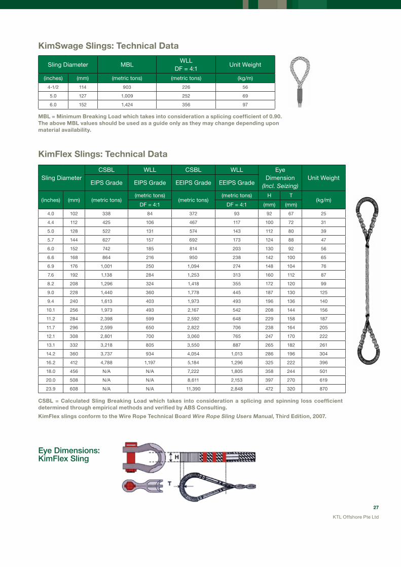
KimSwage Slings: Technical Data
MBL = Minimum Breaking Load which takes into consideration a splicing coefficient of 0.90.The above MBL values should be used as a guide only as they may change depending upon material availability.
KimFlex Slings: Technical Data
CSBL = Calculated Sling Breaking Load which takes into consideration a splicing and spinning loss coefficient determined through empirical methods and verified by ABS Consulting.
KimFlex slings conform to the Wire Rope Technical Board Wire Rope Sling users Manual, Third Edition, 2007.
EyeDimensions:KimFlexSling
Sling Diameter MBLWLL
DF = 4:1 Unit Weight
(inches) (mm) (metric tons) (metric tons) (kg/m)
4-1/2 114 903 226 56
5.0 127 1,009 252 69
6.0 152 1,424 356 97
Sling DiameterCSBL WLL CSBL WLL Eye
Dimension(incl. Seizing)
Unit WeightEIPS Grade EIPS Grade EEIPS Grade EEIPS Grade
(inches) (mm) (metric tons)(metric tons)
(metric tons)(metric tons) H T
(kg/m)DF = 4:1 DF = 4:1 (mm) (mm)
4.0 102 338 84 372 93 92 67 25
4.4 112 425 106 467 117 100 72 31
5.0 128 522 131 574 143 112 80 39
5.7 144 627 157 692 173 124 88 47
6.0 152 742 185 814 203 130 92 56
6.6 168 864 216 950 238 142 100 65
6.9 176 1,001 250 1,094 274 148 104 76
7.6 192 1,138 284 1,253 313 160 112 87
8.2 208 1,296 324 1,418 355 172 120 99
9.0 228 1,440 360 1,778 445 187 130 125
9.4 240 1,613 403 1,973 493 196 136 140
10.1 256 1,973 493 2,167 542 208 144 156
11.2 284 2,398 599 2,592 648 229 158 187
11.7 296 2,599 650 2,822 706 238 164 205
12.1 308 2,801 700 3,060 765 247 170 222
13.1 332 3,218 805 3,550 887 265 182 261
14.2 360 3,737 934 4,054 1,013 286 196 304
16.2 412 4,788 1,197 5,184 1,296 325 222 396
18.0 456 N/A N/A 7,222 1,805 358 244 501
20.0 508 N/A N/A 8,611 2,153 397 270 619
23.9 608 N/A N/A 11,390 2,848 472 320 870
28
KTL Offshore Pte Ltd
Sling Diameter CRBL CSBL WLL WLL Unit Weight
(inches) (mm) (metric tons) (metric tons)(metric tons) (metric tons)
(kg/m)DF = 2.25 DF = 4.0
5.0 128 699 525 233 131 50
5.2 132 757 568 252 142 53
5.4 136 781 586 260 146 55
5.5 140 841 631 280 158 60
5.7 144 905 679 302 170 65
5.7 146 917 688 306 172 66
5.9 150 984 738 328 184 70
6.0 153 1,003 752 334 188 71
6.1 154 1,010 757 337 189 72
6.3 160 1,071 831 369 208 78
6.4 162 1,151 863 384 216 80
6.5 164 1,165 874 388 218 82
6.6 168 1,197 898 399 224 83
7.3 185 1,438 1,078 479 270 104
7.5 191 1,561 1,171 520 293 114
7.6 194 1,583 1,188 528 297 116
8.0 202 1,775 1,332 592 333 127
8.0 204 1,790 1,343 597 336 129
8.1 205 1,798 1,349 599 337 129
8.9 225 2,137 1,603 712 401 154
9.0 229 2,170 1,628 723 407 156
9.1 231 2,269 1,702 756 425 166
9.3 235 2,302 1,727 767 432 168
9.4 238 2,328 1,746 776 437 171
9.4 239 2,393 1,795 798 449 180
9.5 242 2,418 1,814 806 453 182
9.8 248 2,472 1,854 824 463 187
10.3 262 2,803 2,102 934 526 213
10.6 268 2,859 2,144 953 536 218
11.1 282 3,213 2,409 1071 602 247
11.4 289 3,281 2,461 1094 615 282
11.9 301 3,601 2,701 1200 675 282
12.0 306 3,652 2,739 1217 685 288
12.5 318 3,988 2,991 1329 748 320
13.0 331 4,128 3,096 1376 774 333
13.6 345 4,539 3,404 1513 851 366
16.0 406 5,984 4,488 1995 1122 510
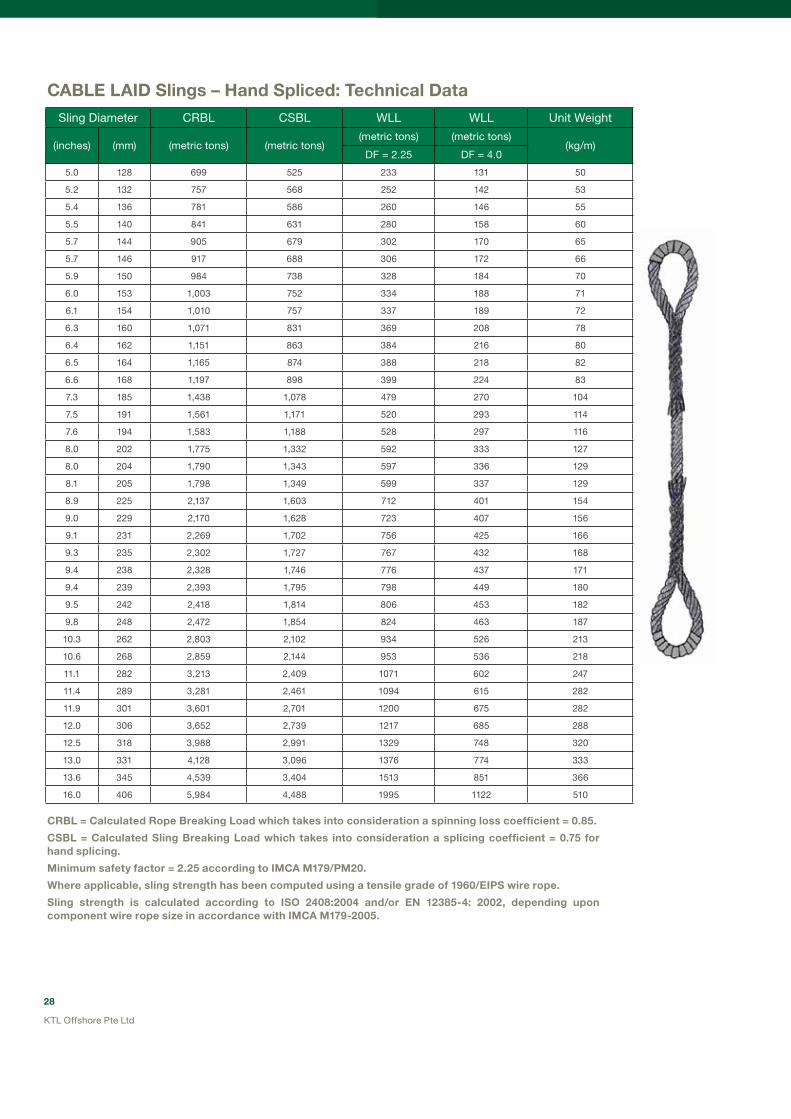
CABLE LAID Slings – Hand Spliced: Technical Data
CRBL = Calculated Rope Breaking Load which takes into consideration a spinning loss coefficient = 0.85.
CSBL = Calculated Sling Breaking Load which takes into consideration a splicing coefficient = 0.75 for hand splicing.
Minimum safety factor = 2.25 according to IMCA M179/PM20.
Where applicable, sling strength has been computed using a tensile grade of 1960/EIPS wire rope.
Sling strength is calculated according to ISO 2408:2004 and/or EN 12385-4: 2002, depending upon component wire rope size in accordance with IMCA M179-2005.

29
KTL Offshore Pte Ltd
SLING STRENGTH:
SLING
Sling Diameter CRBL CSBL WLL WLL Unit Weight
(inches) (mm) (metric tons) (metric tons) DF = 2.25 DF = 4.0 (kg/m)
100 3.9 493 493 219 123 32
102 4.0 503 503 224 126 32
104 4.1 512 512 228 128 33
106 4.2 562 562 250 141 36
108 4.3 571 571 254 143 37
110 4.3 582 582 259 146 37
114 4.5 638 638 283 159 42
116 4.6 648 648 288 162 43
120 4.7 706 706 314 177 45
122 4.8 718 718 319 180 46
126 5.0 773 773 344 193 49
128 5.0 783 783 348 196 50
132 5.2 847 847 377 212 53
135 5.3 867 867 385 217 54
136 5.4 873 873 388 218 55
139 5.5 929 929 413 232 58
140 5.5 935 935 416 234 59
144 5.7 1,007 1,007 447 252 64
148 5.8 1,034 1,034 460 259 66
149 5.9 1,043 1,043 464 261 67
152 6.0 1,090 1,090 484 272 72
153 6.0 1,099 1,099 488 275 72
154 6.1 1,099 1,099 488 275 73
159 6.2 1,213 1,213 539 303 77
160 6.3 1,213 1,213 539 303 78
162 6.4 1,236 1,236 549 309 79
162 6.4 1,250 1,250 556 313 83
164 6.5 1,273 1,273 566 318 85
185 7.3 1,564 1,564 695 391 99
191 7.5 1,704 1,704 758 426 114
194 7.6 1,731 1,731 769 433 116
200 7.9 1,860 1,860 827 465 124
204 8.0 1,896 1,896 842 474 129
205 8.1 1,896 1,896 842 474 129
225 8.9 2,254 2,254 1,002 564 154
229 9.0 2,285 2,285 1,015 571 156
231 9.1 2,412 2,412 1,072 603 166
235 9.3 2,443 2,443 1,086 611 168
238 9.4 2,473 2,473 1,099 618 171
239 9.4 2,611 2,611 1,161 653 180
242 9.5 2,641 2,641 1,174 660 182
239 9.4 2,611 2,611 1,161 653 180
242 9.5 2,641 2,641 1,174 660 182
248 9.8 2,706 2,706 1,202 676 187
262 10.3 3,052 3,052 1,357 763 213
KIMLOCK CABLE LAID Slings – Resin Socketed: Technical Data

30
KTL Offshore Pte Ltd
CRBL = Calculated Rope Breaking Load which takes into consideration a spinning loss coefficient = 0.85.
CSBL = Calculated Sling Breaking Load which takes into consideration a splicing coefficient = 1.00 for resin socketing.
Minimum safety factor = 2.25 according to IMCA M179/PM20. However, KTL Offshore recommends 4.0 for offshore engineered lifts.
Sling strength has been computed using a tensile grade of EEIPS wire rope.
SLING STRENGTH:
SLING
Sling Diameter CRBL CSBL WLL WLL Unit Weight
(inches) (mm) (metric tons) (metric tons) DF = 2.25 DF = 4.0 (kg/m)
268 10.6 3,121 3,121 1,387 780 218
283 11.1 3,363 3,363 1,494 841 232
283 11.1 3,483 3,483 1,548 871 248
289 11.4 3,541 3,541 1,574 885 253
301 11.9 3,929 3,929 1,746 982 282
306 12.0 4,111 4,111 1,827 1,028 288
318 12.5 4,525 4,525 2,011 1,131 320
331 13.0 4,625 4,625 2,055 1,156 332
345 13.6 4,972 4,972 2,210 1,243 366
406 16.0 7,062 7,062 3,139 1,765 505

31
KTL Offshore Pte Ltd
KimFlex Grommets: Technical Data
Grommet diameterCGBL CGBL Unit Weight
(In Double Part)EIPS EEIPS
(inches) (mm) (metric tons) (metric tons) (kg/m)
4.0 102 675 743 50
4.4 112 850 933 63
5.0 128 1,044 1,148 77
5.7 144 1,254 1,384 94
6.0 152 1,483 1,627 111
6.6 168 1,728 1,901 131
6.9 176 2,002 2,189 152
7.6 192 2,275 2,506 174
8.2 208 2,592 2,837 198
9.0 228 2,880 3,557 250
9.4 240 3,226 3,946 279
10.1 256 3,946 4,334 311
11.2 284 4,795 5,184 374
11.7 296 5,198 5,645 410
12.1 308 5,602 6,120 445
13.1 332 6,437 7,099 522
14.2 360 7,474 8,107 608
16.2 412 9,576 10,368 792
KimFlex Grommets:
CGBL = Calculated Grommet Breaking Load
The WLL is calculated as follows:
WLL = CGBL x EB Safety Factor Where EB = 1 – 0.5 √D/d
And:D = Minimum bend diameterd = Grommet body diameter
32
KTL Offshore Pte Ltd
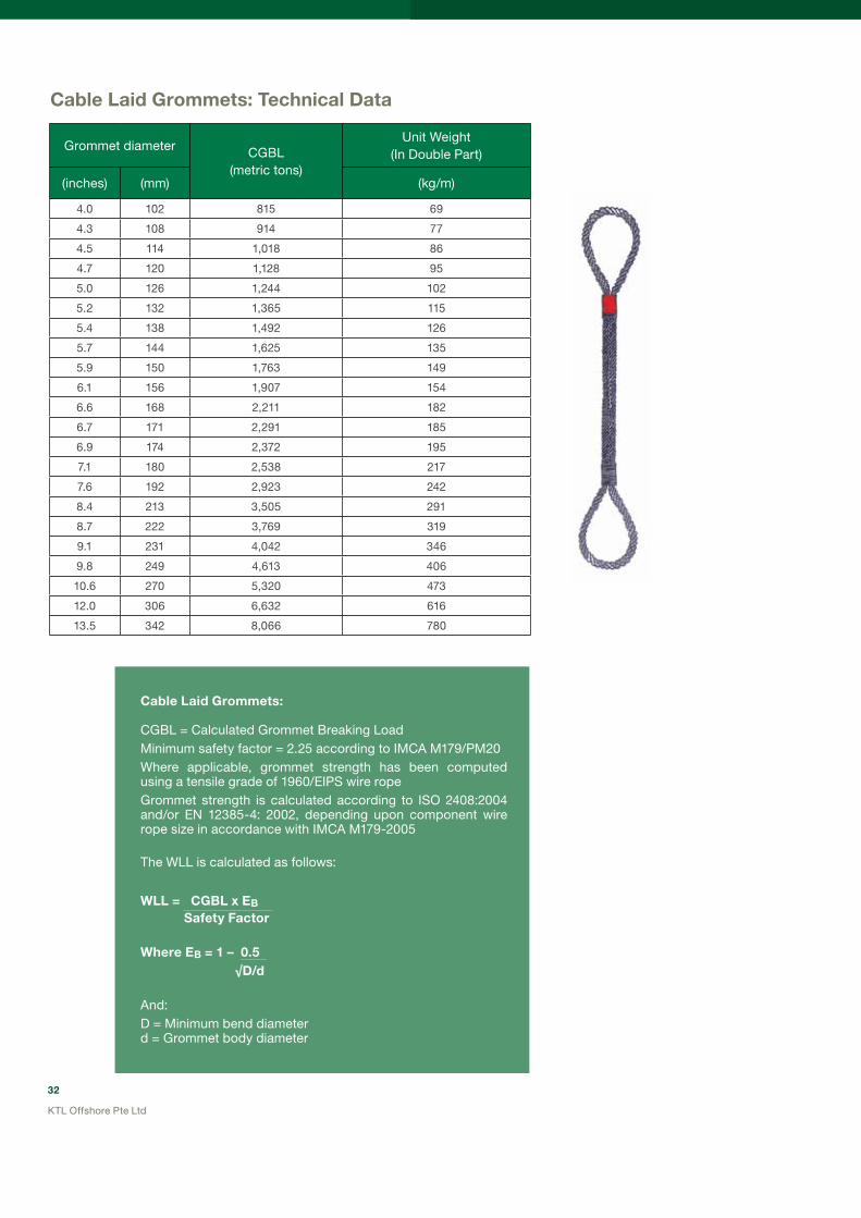
Cable Laid Grommets:
CGBL = Calculated Grommet Breaking LoadMinimum safety factor = 2.25 according to IMCA M179/PM20 Where applicable, grommet strength has been computed using a tensile grade of 1960/EIPS wire ropeGrommet strength is calculated according to ISO 2408:2004 and/or EN 12385-4: 2002, depending upon component wire rope size in accordance with IMCA M179-2005
The WLL is calculated as follows:
WLL = CGBL x EB Safety Factor Where EB = 1 – 0.5 √D/d
And:D = Minimum bend diameterd = Grommet body diameter
Cable Laid Grommets: Technical Data
Grommet diameter CGBL(metric tons)
Unit Weight(In Double Part)
(inches) (mm) (kg/m)
4.0 102 815 69
4.3 108 914 77
4.5 114 1,018 86
4.7 120 1,128 95
5.0 126 1,244 102
5.2 132 1,365 115
5.4 138 1,492 126
5.7 144 1,625 135
5.9 150 1,763 149
6.1 156 1,907 154
6.6 168 2,211 182
6.7 171 2,291 185
6.9 174 2,372 195
7.1 180 2,538 217
7.6 192 2,923 242
8.4 213 3,505 291
8.7 222 3,769 319
9.1 231 4,042 346
9.8 249 4,613 406
10.6 270 5,320 473
12.0 306 6,632 616
13.5 342 8,066 780

33
KTL Offshore Pte Ltd
KimFlex ultra Short Grommets: Technical Data
Grommet Diameter
CGBL CGBLUnit Weight
(In Double Part)Minimum Effective
LengthEIPS EEIPS
(inches) (mm) (metric tons) (metric tons) (kg/m) (metres)
3.1 80 161 15 1.00
3.8 96 583 22 1.00
4.4 112 351 30 1.25
5.0 128 438 39 1.25
6.0 152 625 55 1.25
6.9 176 845 74 1.50
7.6 192 957 88 1.75
8.2 208 1,097 103 1.75
8.8 224 1,306 120 2.00
9.1 232 1,381 129 2.00
10.1 256 1,697 157 2.25
10.7 272 1,931 177 2.25
11.0 280 2,038 188 2.25
11.3 288 2,157 198 2.50
12.0 304 2,410 221 2.50
12.6 320 2,621 245 2.75
13.2 336 2,808 3,101 270 2.75
13.9 352 3,253 3,578 296 3.00
15.1 384 3,697 4,079 352 3.25
15.7 400 4,212 4,603 383 3.50
16.4 416 4,212 4,603 414 3.50
18.0 456 5,242 5,780 500 3.75
18.9 480 5.827 6,412 558 3.75
20.2 512 6,412 7,043 623 4.00
22.4 568 7,792 8,424 749 5.00
24.3 616 9,103 9,945 889 5.50
26.1 664 10,460 11,536 1044 6.00
KIMFLEX ultra Short Grommets:
CGBL = Calculated Grommet Breaking Load
The WLL is calculated as follows:
WLL = CGBL x EB Safety Factor Where EB = 1 – 0.5 √8D/d
And:D = Minimum bend diameterd = Grommet body diameter

34
KTL Offshore Pte Ltd
Heavy Lift Synthetic GrommetsKimPlasma Grommets - High Strength, Light Weight, Easy and Safe Inspection
Cortland PSR’s Plasma grommets have been used in the deep waters in the Gulf of Mexico using DNv approved safety factors and lifting conditions.
At KTL Offshore, our KimPlasma grommets are produced using our rigorous Quality Control Plan (QCP) procedures that have seen us manufacture thousands of heavy lift wire rope slings over the last decade.
Our Engineered Length Control (ELC) technique enables us to manufacture KimPlasma grommets to exact tolerances under a specified load – bringing the customer the most advanced and technologically advanced heavy lift solution in the world.
Features and benefits of the KimPlasma Heavy Lift (HL) grommet range:
• Completely torque free
• Easy to inspect – no hidden components
• Damaged strands can be replaced in the field
• Re-splicing can be done in the field
• Highest strength-to-weight ratio of any sling or grommet
• Each grommet is individually engineered for a specific length, proof load tested and provided with 3rd party certification

35
KTL Offshore Pte Ltd
KimPlasma Grommets – Technical Data
The KimPlasma Grommet is spliced by using a standard tucked hand splice. The splice is positively locking and will not slip under any circumstances. This splice does not require any tools and can be done in the field by suitably trained personnel. Protection at the eye is provided by a Nylon cover, which is easily removable and replaceable.
Product CodeDiameter Diameter Circ. Circ. Weight
Splice Length (Total)
Spliced MBL
mm inches mm inches Kg/100m mm Metric Tons
KPG-HL-98 98 4.1 310 12.9 14.5 9,148 1,213
KPG-HL-102 102 4.3 322 13.4 15.4 9,500 1,280
KPG-HL-104 104 4.3 326 13.6 16.3 9,676 1,348
KPG-HL-108 108 4.5 338 14.1 17.1 10,028 1,415
KPG-HL-110 110 4.6 350 14.6 18.0 10,380 1,482
KPG-HL-112 112 4.7 358 14.9 19.1 10,556 1,550
KPG-HL-118 118 4.9 370 15.4 20.3 10,908 1,617
KPG-HL-120 120 5.0 382 15.9 21.5 11,259 1,684
KPG-HL-125 125 5.2 394 16.4 22.7 11,611 1,752
KPG-HL-130 130 5.4 406 16.9 23.9 11,963 1,819
KPG-HL-132 132 5.5 418 17.4 25.1 12,315 1,887
KPG-HL-140 140 5.8 442 18.4 27.9 13,019 2,021
KPG-HL-144 144 6.0 454 18.9 29.7 13,371 2,089
KPG-HL-146 146 6.1 466 19.4 31.6 13,723 2,156
KPG-HL-150 150 6.3 478 19.9 33.4 14,074 2,223
KPG-HL-156 156 6.5 494 20.6 35.3 14,602 2,291
KPG-HL-160 160 6.7 506 21.1 37.2 14,954 2,358
KPG-HL-166 166 6.9 523 21.8 39.5 15,482 2,426
KPG-HL-172 172 7.2 542 22.6 42.1 16,010 2,493
KPG-HL-178 178 7.4 559 23.3 44.9 16,537 2,560
KPG-HL-182 182 7.6 578 24.1 47.8 17,065 2,628
KPG-HL-190 190 7.9 595 24.8 50.8 17,593 2,695
Notes:
1. The grommet MBL has already factored in a splicing efficiency.
2. MBL is attained as long as D/d at the bearing points is greater than or equal to 3.
3. For lower bending ratios, the MBL must be de-rated. Please consult KTL Offshore.
4. For engineered lifts the SWL may be calculated according to DNv Rules for Marine Operations, Part 2 Chapter 5, January 1996.

36
KTL Offshore Pte Ltd
HEAvy LIFT SHACKLES As The Largest Crosby Distributor Outside The uSA, KTL Offshore Offers A vast Range Of Shackles Suitable For Heavy Lifting, up To WLL 1550t
Around the world, applications such as heavy construction, oil exploration and production require shackles that are able to withstand demanding, extreme field conditions. Crosby’s time-tested shackles, which have a reputation of being “Job Tough”, are regularly deployed in these applications.
WhyIsCrosby’s G-2160 Wide Body ShackleTheWorld’sPremiumBrandHeavyLiftShackle?
There are compelling reasons why Crosby’s G-2160 is regarded as the premium heavy lift shackle the world over:
• Forged shackle are produced through closed-die forging rather than open-die forging, which requires extensive grinding. This ensures dimensional accuracy and improved surface quality.
• Cast shackle (200t and above as from January 2008) are made in an air set casting process to assure dimensional accuracy and improved surface quality.
• All ratings are in metric tons, embossed on the side of bow with raised lettering that is easy to read and places no stress on the shackle.
• Increase in shackle bow radius provides a minimum 58% gain in sling bearing surface and eliminates need for a thimble.
• The pin is non-rotating, with weld on handles for easier use (300t and larger).
• Crosby products meet or exceed all the requirements of ASME B30.26 including identification, ductility, design factor, proof load and temperature requirements.
• All G-2160 shackles are individually proof tested and non-destructive tested.
• Shackles are Quenched and Tempered and meet DNV impact requirements of 42 joules at -20°C.
• Full data pack of certification is provided with all wide body shackles as follows:
* NDT certification* Proof load test certificate* Material certification—chemistry, Charpy, tensile* Certificate of conformance* DNV Product Type Approval
CrosbyValueAddedFeature:• Crosby’s G-2160 has DNv
Type Approval which includes the following certification:
* Manufacturing Survey Assessment (MSA) which includes a full audit of the Crosby manufacturing facility.
* Type Approval Certificate which is signed and stamped by DNV and includes a full design assessment of the product type.
* Product Certificate signed and stamped by DNV in which the appropriate tests are submitted for review and is shipped with the shackle.

37
KTL Offshore Pte Ltd
CrosbyG-2160WideBodyShackles—Dimensions
Mega Lift Range
Heavy Lift Range
Low Range
* ultimate Load is 5 times the Working Load Limit. † Forged Alloy Steel. Proof Load is 2 times the Working Load Limit.†† Cast Alloy Steel. Proof Load is 1.33 times the Working Load Limit.
+Before November 2007, forged; after this date, cast.
Working LoadLimit*(metric tons)
G-2160 Stock No.
Weight Each (lbs.)
Dimensions (inch)
AB
+/- .25C
D+/- .02
E G H J K P R
†† 1250 1021272 5706 49.86 16.93 9.15 11.81 21.00 10.43 36.61 20.87 12.70 46.26 65.35
†† 1550 1021281 7025 54.87 18.31 10.58 12.60 23.82 15.92 42.32 22.82 13.28 49.41 73.43
Working LoadLimit *(metric tons)
G-2160 Stock No.
Weight Each (lbs.)
Dimensions (inch)
AB
+/- .25C
D+/- .02
E G H J K P R
† 30 1021575 25 7.73 2.37 1.38 1.63 3.50 2.50 7.00 3.13 2.50 8.50 11.38
† 40 1021584 35 9.32 2.88 1.75 2.00 4.00 1.75 8.13 3.75 3.00 10.62 13.62
† 55 1021593 71 10.41 3.25 2.00 2.27 4.63 2.00 9.42 4.50 3.50 12.26 15.63
† 75 1021290 99 14.37 4.13 2.12 2.75 5.00 2.55 11.60 4.75 3.64 12.28 18.41
† 125 1021307 161 16.51 5.12 2.56 3.15 5.71 3.15 14.43 5.91 4.33 14.96 22.65
Working LoadLimit*(metric tons)
G-2160 Stock No.
Weight Each (lbs.)
Dimensions (inch)
AB
+/- .25C
D+/- .02
E G H J K P R
† 200+ 1021316 500 20.67 5.91 3.35 4.12 7.28 4.33 18.98 8.07 5.41 19.49 29.82
†† 200+ 1021316 500 20.67 5.91 3.35 4.12 7.84 4.33 18.98 8.07 5.41 19.49 29.82
† 300+ 1021325 811 24.20 7.38 4.00 5.25 9.25 5.47 23.69 10.38 6.31 23.38 37.26
†† 300+ 1021325 811 24.20 7.38 4.00 5.25 10.00 5.47 23.69 10.38 6.31 23.38 37.26
†† 400 1021334 1041 30.06 8.66 5.16 6.30 11.81 6.30 22.71 12.60 7.28 27.17 38.78
†† 500 1021343 1378 32.99 9.84 5.59 7.09 12.52 6.69 24.88 13.38 8.86 31.10 42.71
†† 600 1021352 1833 35.39 10.83 6.04 7.87 13.78 7.28 27.64 14.56 9.74 34.06 47.24
†† 700 1021361 2446 38.91 11.81 6.59 8.46 14.80 7.87 29.04 15.74 10.63 37.01 50.17
†† 800 1021254 3016 43.50 12.80 7.19 9.06 15.75 8.27 29.62 16.54 10.92 38.39 52.09
†† 900 1021389 3436 43.60 13.78 7.78 9.84 16.93 8.66 30.02 17.32 11.51 40.35 54.04
†† 1000 1021370 4022 45.98 14.96 8.33 10.63 17.72 9.06 30.02 18.12 12.11 42.32 55.32

38
KTL Offshore Pte Ltd
Nominal
Shackle
Size
(inches)
Working
Load
Limit*
(metric
tons)
Stock
No. Weight
Each
(lbs.)
Dimensions
(inches)
A B
(Bend
Diameter)
C
D E F G H J K L A EG-2140
Galv.
For shackles under 200t in capacity, see Shackles under General engineering Slings, Shackles and Grommets
4-3/4 ** † 200 1021414 450.0 7.25 10.50 6.00 4.75 15.69 3.75 21.00 20.59 29.25 11.00 4.50 .25 .25
5 ** † 250 1021432 600.0 8.50 12.00 6.50 5.00 20.06 3.88 24.50 22.06 35.00 13.00 4.50 .25 .25
6 ** † 300 1021450 775.0 8.38 12.00 6.75 6.00 19.56 6.43 25.00 24.44 35.25 13.00 5.00 .25 .25
7 ** † 400 1021478 1102.0 8.25 14.00 7.25 7.00 22.56 6.50 26.00 28.06 40.25 13.00 6.00 .25 .25
7-1/2 ** † 500 N/A 1556.0 8.31 15.00 7.50 7.63 25.19 6.28 28.00 28.12 44.00 13.00 7.50 .25 .25
Tolerance
Crosby’sAlloyRangeG-2140 Bolt Type Shackle
What makes Crosby’s G-2140 alloy shackles superior to the competition?
CrosbyValueAddedFeatures:• Bow cross section is oval and not round, leading to
lower bending stress and increased fatigue life.
• Crosby’s G-2140 has ABS Type Approval, which includes the following certification:
* Manufacturing Survey Assessment (MSA) which includes a full audit of the Crosby manufacturing facility.
* Type Approval Certificate which is signed and stamped by ABS and includes a full design assessment of the product type.
* Product Certificate signed and stamped by ABS where the appropriate tests are submitted for review and shipped with the shackle.
un-retouched drawings of actual Stress Analysis performed by Crosby Engineering showing the lower stress levels present in the Crosby G-2140 shackle compared to a competitor’s product.
In addition to the benefits above, the G-2140 range also features:
*Note: Maximum Proof Load is 2.0 times the Working Load Limit.Minimum ultimate Load is 4 times the Working Load Limit on 200 through 400 metric tons. ** Cast Alloy Steel.† Furnished with round head bolts with welded handle.
• Alloy bows and bolts.
• Forged alloy steel 30 through 175 metric tons. Cast alloy steel 200 through 400 metric tons. Working Load Limit is permanently shown on every shackle.
• All sizes are individually proof tested to 2.0 times the Working Load Limit.
• Pins are galvanised and painted red.
• Shackles are Quenched and Tempered and can meet DNV impact requirements of 42 joules at -200C.
• Crosby products meet or exceed all the requirements of ASME B30.26 including identification, ductility, design factor, proof load and temperature requirements.
• All G-2140 shackles are individually proof tested and for 200t and above, non-destructive tested as well.

39
KTL Offshore Pte Ltd
Application Information—Heavy Lift Shackles
ConsiderTheEffectsOfBending
As discussed under the Heavy Lift Slings and Grommets section, the bending effect on slings and grommets can have a significant effect on strength. Very often the connection point between the sling or grommet and the shackle represents the minimum-bending diameter to be considered in the D/d equation.
The bending diameter of the shackle is usually situated at the bow—unless the pin is used to connect the sling, in which case the pin diameter becomes the minimum bend diameter. It is recommended to connect the slings or grommet to the bow of the shackle and use the pin to connect to the structure being lifted. In this way, the full advantage of the larger bow diameter in raising the D/d ratio between sling and shackle can be gained.
Wide body shackles have much larger bow diameters and hence provide higher D/d ratios and greater bending efficiency.
PointLoading
Crosby shackles may be point loaded at the bows. At the pins, point loading is also acceptable but Crosby recommends an 80% spread over the pin as “best practice”.
BalanceTheLoad
Crosby shackles symmetrically loaded with two leg slings having a maximum included angle of 120° can be utilised to full Working Load Limit. Never exceed a 120° included angle for any shackle application.
The load should always be balanced to prevent tilting. Use spacers around the bearing point on the shackle pin to stabilise the load if necessary.
ConnectingShacklesTogether
Connecting two Crosby shackles either bow-to-bow or bow-to-pin is entirely acceptable. Two Crosby shackles of the same size and type can be fitted together in a bow-to-bow arrangement.
Connecting two Crosby shackles pin-to-pin is acceptable as long as the load can be balanced.

40
KTL Offshore Pte Ltd
SideLoading
Side loading of Crosby shackles is allowed, although the WLL must be reduced according to the following table:
For other brands of shackles, side loading may not always be recommended - please check their latest product brochures for more information.
CompleteEquipment
The shackle comes complete as a tested assembly consisting of the shackle bow, bolt (pin), nut and cotter pin.
The cotter pin acts as a safety pin to prevent the nut from disengaging should the load cause the pin to rotate. The cotter pin should always be present during use of the shackle.
Although Crosby Wide Body shackles have serialised identification numbers on the bows and pins, it is not necessary for the number on the bow and pin to match each other on any individual shackle.
Side Loading Reduction Chart (from Crosby Catalogue)For Screw Pin and Bolt Type Shackles Only
Angle of Side Loadfrom Vertical In-line of shackle
Adjusted Working Load Limit
00 In-line 100% of rated Working Load Limit
450 from In-line 70% of rated Working Load Limit
900 from In-line 50% of rated Working Load Limit

41
KTL Offshore Pte Ltd
MOORING SySTEMS AND DECK EQuIPMENTThe Complete Mooring System From The Anchors To The Winches
Anchors
KTL Offshore has established a winning combination of quality and economics: High Holding Power (HHP) anchors made in China with project management and 3rd party inspection from Singapore.
This perfect combination has seen us deliver anchors of up to 25t to the world’s premium contractors for their offshore projects.
(Above) Anchors are made in China with 3rd party inspection and witness of testing from Singapore.

42
KTL Offshore Pte Ltd
CMICSTAnchor(HighHoldingPower)
Nominal Weight
(kg)
Dimensions (mm)
A B C D E F G H L N W
500 2045 2155 1252 50 186 850 324 905 260 74 1685
1500 2952 3108 1805 68 268 1225 645 1305 345 100 2430
2000 3250 3420 1986 82 235 1345 510 1440 401 115 2675
3000 3720 3916 2275 90 338 1540 585 1645 430 125 3060
4000 4095 4310 2505 100 372 1695 645 1810 465 135 3368
5000 4410 4645 2698 110 400 1825 695 1950 535 150 3628
6000 4685 4935 2865 110 425 1940 738 2072 555 157 3855
7000 4932 5195 3016 117 448 2042 774 2180 600 163 4058
8000 5158 5430 3156 130 468 2135 812 2280 665 177 4245
9000 5365 5648 3282 135 486 2220 845 2372 688 182 4415
10000 5556 5850 3400 140 504 2300 875 2456 710 188 4572
11000 5735 6038 3510 145 520 2375 905 2535 735 193 4720
12000 5904 6216 3612 150 536 2445 930 2610 755 198 4858
13500 5140 6465 3756 155 558 2542 968 2715 778 205 5052
15000 6275 6695 3890 160 578 2635 1002 2810 810 214 5235
18000 6668 7115 4135 170 615 2800 1065 2985 855 224 5562
20000 6905 7370 4282 180 635 2900 1105 3092 890 234 5760
22000 7128 7608 4420 190 655 2995 1140 3192 945 246 5945
25000 7438 7940 4612 195 685 3125 1190 3330 958 252 6205
Efficiency range: 33 to 55Slender anchor with excellent penetration.Approximate holding capacity = efficiency x weightSTS anchor (below) is supplied with a jagged edge for very hard anchoring conditionsAnchors are shipped with the flukes and shanks disassembled for easier transportation.

43
KTL Offshore Pte Ltd
CMIC(Flipper)DeltaAnchor(HighHoldingPower)
Nominal Weight
(kg)
Dimensions (mm)
TL W F H S D1Proof Load
(kN)300 1380 1200 960 465 1080 45 98
500 1725 1500 1200 570 1350 48 143
750 1950 1700 1360 650 1530 50 198
1000 2150 1870 1500 710 1680 62 250
1500 2460 2140 1710 815 1920 70 350
2000 2715 2360 1890 900 2125 75 435
2500 2925 2540 2035 970 2290 80 510
3000 3105 2700 2160 1030 2430 90 576
3500 3240 2845 2280 1087 2565 90 635
4000 3375 2953 2315 1140 2650 100 686
5000 3658 3200 2560 1225 2900 110 776
6000 3935 3405 2720 1310 3125 110 875
7000 4120 3580 2860 1360 3220 117 968
7500 4215 3666 2935 1390 3295 124 1005
8000 4315 3750 3000 1425 3380 130 1048
9000 4490 3874 3120 1480 3512 135 1108
10000 4725 4100 3280 1560 3690 140 1172
11000 4868 4140 3310 1600 3750 145 1238
12000 4960 4275 3420 1640 3860 150 1300
13500 5120 4450 3560 1700 4000 155 1408
15000 5345 4600 3685 1735 4160 160 1520
18000 5678 4890 3919 1840 4418 170 1710
20000 5880 5065 4050 1900 4570 175 1840
Efficiency range: 14 to 26Anchor has relatively short shank with stabilizers.Approximate holding capacity =efficiency x weightAnchors are shipped with the flukes and shanks disassembled for easier transportation.

44
KTL Offshore Pte Ltd
Chain Diameter(mm)
Grade 2 Grade 3 Grade ORQ Approx. weight
(27.5m) (kg)Proof load (kN) Breaking load (kN) Proof load (kN) Breaking load(kN)
Proof load(kN)
Breaking load (kN)
22 200 280 280 401
24 237 332 332 476
26 278 389 389 556
28 321 449 449 642
30 368 514 514 735
32 417 583 583 833
34 468 655 655 937
36 523 732 732 1050
38 581 812 812 1160 870 1250 905
40 640 896 896 1280 1003
42 703 981 981 1400 1060 1510 1106
44 769 1080 1080 1540 1160 1650 1213
46 837 1170 1170 1680 1326
48 908 1270 1270 1810 1370 1950 1444
50 981 1370 1370 1960 1480 2110 1567
52 1060 1480 1480 2110 1590 2270 1695
54 1140 1590 1590 2270 1710 2440 1828
56 1220 1710 1710 2430 1830 2620 1966
58 1290 1810 1810 2600 1960 2790 2109
60 1380 1940 1940 2770 2090 2980 2257
62 1470 2060 2060 2940 2220 3170 2410
64 1560 2190 2190 3130 2350 3360 2568
66 1660 2310 2310 3300 2490 3560 2731
68 1750 2450 2450 3500 2640 3760 2899
70 1840 2580 2580 3690 2780 3970 3072
73 1990 2790 2790 3990 3010 4290 3341
76 2150 3010 3010 4300 3240 4620 3621
78 2260 3160 3160 4500 3400 4850 3814
81 2410 3380 3380 4820 3640 5190 4113
84 2580 3610 3610 5160 3890 5550 4424
87 2750 3850 3850 5500 4140 5920 4745
90 2920 4090 4090 5840 4410 6290 5078
92 3040 4260 4260 6080 4580 6540 5326
95 3230 4510 4510 6440 4860 6930 5679
97 3340 4680 4680 6690 5040 7190 5920
100 3530 4940 4940 7060 5320 7600 6292
102 3660 5120 5120 7320 5510 7870 6546
105 3850 5390 5390 7700 5800 8280 9637
107 3980 5570 5570 7960 6000 8560 7204
111 4250 5940 5940 8480 6400 9130 7752
114 4440 6230 6230 8890 6700 9560 8177
117 4650 6510 6510 9300 7010 10010 8613
120 4850 6810 6810 9720 7320 10450 9060
122 5000 7000 7000 9990 7530 10750 9360
124 5140 7200 7200 10280 7740 11060 9675
127 5350 7490 7490 10710 8070 11520 10148
Anchor Chain—Table Of Minimum Breaking Load And Proof Load
AnchorChainAndAccessoriesWe stock a wide range of anchor chains and accessories suitable for offshore use. This includes:• Swivels (various types)
• Kenter links
• C-links
• Pear links
• Hinge links
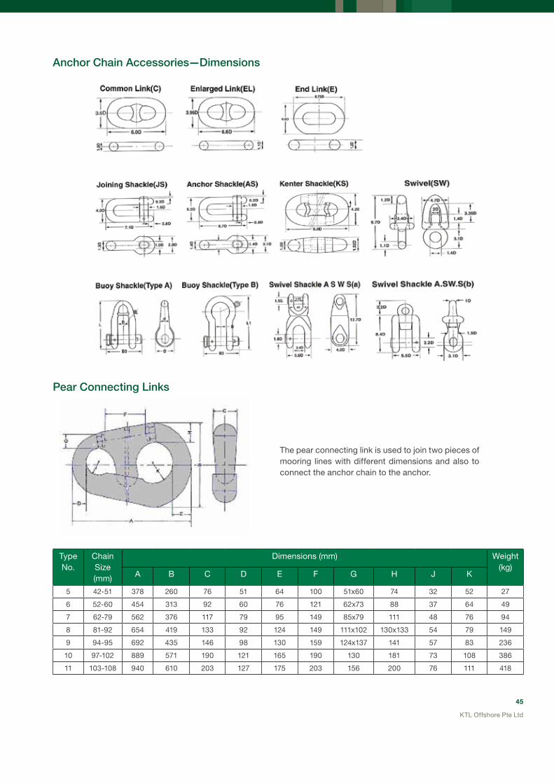
45
KTL Offshore Pte Ltd
AnchorChainAccessories—Dimensions
PearConnectingLinks
The pear connecting link is used to join two pieces of mooring lines with different dimensions and also to connect the anchor chain to the anchor.
TypeNo.
Chain Size (mm)
Dimensions (mm) Weight(kg)
A B C D E F G H J K
5 42-51 378 260 76 51 64 100 51x60 74 32 52 27
6 52-60 454 313 92 60 76 121 62x73 88 37 64 49
7 62-79 562 376 117 79 95 149 85x79 111 48 76 94
8 81-92 654 419 133 92 124 149 111x102 130x133 54 79 149
9 94-95 692 435 146 98 130 159 124x137 141 57 83 236
10 97-102 889 571 190 121 165 190 130 181 73 108 386
11 103-108 940 610 203 127 175 203 156 200 76 111 418

46
KTL Offshore Pte Ltd
Fairleaders,HorizontalAndVerticalSheaves
Fairleaders can be supplied in the standard double sheave swivel head design, or as a single sheave swivel head type.
The single sheave type has the advantage of increasing the D/d ratio between the sheave and wire rope, thereby resulting in significantly improved wire rope life while the double sheave arrangement provides a back up in case one of the sheaves should become unusable.
(Left) McKissick single sheave fairleaders and (below) horizontal sheaves for 3” diameter anchor lines supplied by KTL Offshore (in 2007) to one of the largest derrick barges in the world – DB 101.
Precision engineered and custom made!
McKissick (part of the Crosby Group) engineering is respected and trusted throughout the world – brought to you by KTL Offshore.
KTL Offshore has supplied vertical and horizontal sheaves for many offshore vessels where quality is of paramount importance.
For offshore pipelay operations, tapered roller bearings are strongly recommended for use in both the sheaves and barrel. For underwater use, special seals and self-lubrication bushings can be installed.
OtherDeckEquipment
We supply other deck equipment such as:
• Smit brackets • Chocks • Capstans

47
KTL Offshore Pte Ltd
McKissickVertical(Type461)AndHorizontal(Type463)LeadSheaves
Figure No.Lead
Sheave Stock No.
Sheave Diameter
(mm)
Standard Wire Rope Size (mm)
Weight Each (kg)
Dimensions (mm)
A B C D
461-18 239753 457 22 227 305 508 279 38.1
461-24 131574 610 32 227 381 660 356 38.1
461-26 238120 660 38 299 406 711 381 38.1
461-36 148389 914 42 386 508 914 495 50.8
461-40 136285 1016 50 910 584 1067 572 50.8
461-42 130753 1067 64 1814 711 1321 648 63.5
463-26 4440359 660 26 448 838 838 95.5 38.1
463-30 1404177 762 32 556 940 940 89.0 38.1
463-36 146522 914 38 862 1092 1092 89.0 38.1
463-42 1406525 1067 44 1350 1270 1270 111 51.0
463-48 131583 1219 50 1630 1397 1397 118 51.0
463-60 123164 1524 64 2900 1727 1727 146 51.0
FurnishTheFollowingImportantInformationWhenOrdering:
• A,B, and C dimensions.
• Line pull in pounds and degree of wrap.
• Line speed.
• Diameter of wire rope
• Roller bearings, bronze bushings, or sealed double row tapered bearings.
GuideAndControlYourDeckLinesWithMcKissick’s®DeckMountedWireRopeSheaves.BuiltToYourSpecificRequirements.
• Extra heavy construction, built to withstand breaking strength of indicated rope (EIPS, EEIPS or higher).
• Flame-hardened sheaves, machined grooves for proper rope size.
• For special requirements, contact KTL Offshore.

48
KTL Offshore Pte Ltd
Figure No.
457 Stock No.
Sheave Diameter
(mm)
Wire Rope
Size (mm)
Weight Each (kg)
Dimensions (mm)
A B C D E F G H J K L M
B-10-D 8073880 254 26 136 273 114 89.0 19.1 127 257 171 556 129 241 114 279
B-12-D 8073924 305 32 272 324 127 127 19.1 162 314 203 679 154 279 133 330
B-16-D 8079379 406 38 590 432 178 152 25.4 214 451 273 938 205 457 203 508
B-20-D 8074022 508 44 1134 533 229 216 25.4 286 557 324 1167 256 533 254 622
B-24-D 8074111 610 52 1633 641 279 254 31.8 324 673 375 1372 306 584 279 686
B-30-D 8097347 762 64 5443 838 330 254 51.0 359 861 521 1740 383 762 381 762
McKissickDoubleSheaveDeckMountedAnchorFairleader(457)
DeckMountedAnchorFairleader
• Barrel and sheaves equipped with sealed double row tapered bearings.
• Extra heavy construction, built to withstand breaking strength of indicated rope at 90 degree sheave wrap and 45 degree head swing.
• All bearings Alemite-lubricated.
• Custom Anchor Fairleader sets available.
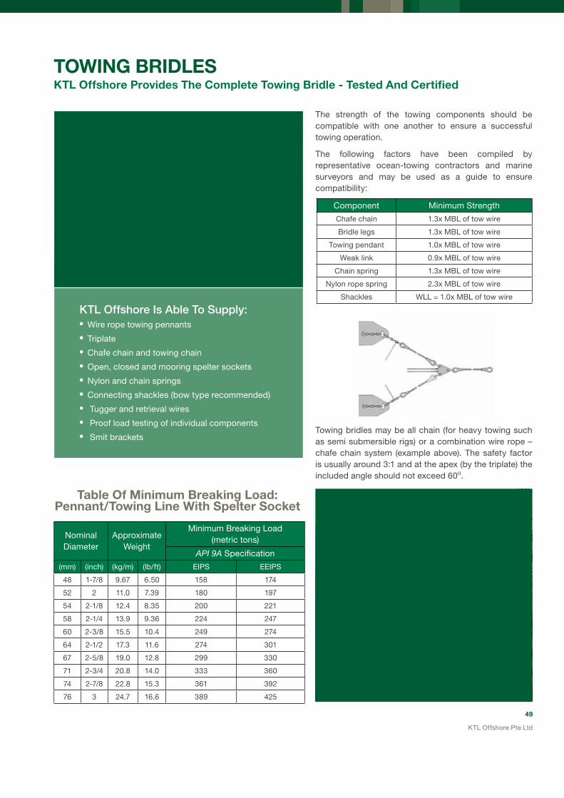
49
KTL Offshore Pte Ltd
Nominal Diameter
Approximate Weight
Minimum Breaking Load(metric tons)
aPi 9a Specification
(mm) (inch) (kg/m) (lb/ft) EIPS EEIPS
48 1-7/8 9.67 6.50 158 174
52 2 11.0 7.39 180 197
54 2-1/8 12.4 8.35 200 221
58 2-1/4 13.9 9.36 224 247
60 2-3/8 15.5 10.4 249 274
64 2-1/2 17.3 11.6 274 301
67 2-5/8 19.0 12.8 299 330
71 2-3/4 20.8 14.0 333 360
74 2-7/8 22.8 15.3 361 392
76 3 24.7 16.6 389 425
TOWING BRIDLESKTL Offshore Provides The Complete Towing Bridle - Tested And Certified
The strength of the towing components should be compatible with one another to ensure a successful towing operation.
The following factors have been compiled by representative ocean-towing contractors and marine surveyors and may be used as a guide to ensure compatibility:
Table Of Minimum Breaking Load:Pennant/Towing Line With Spelter Socket
Component Minimum Strength
Chafe chain 1.3x MBL of tow wire
Bridle legs 1.3x MBL of tow wire
Towing pendant 1.0x MBL of tow wire
Weak link 0.9x MBL of tow wire
Chain spring 1.3x MBL of tow wire
Nylon rope spring 2.3x MBL of tow wire
Shackles WLL = 1.0x MBL of tow wire
Towing bridles may be all chain (for heavy towing such as semi submersible rigs) or a combination wire rope – chafe chain system (example above). The safety factor is usually around 3:1 and at the apex (by the triplate) the included angle should not exceed 60o.
KTLOffshoreIsAbleToSupply:•Wire rope towing pennants
•Triplate
•Chafe chain and towing chain
•Open, closed and mooring spelter sockets
•Nylon and chain springs
•Connecting shackles (bow type recommended)
• Tugger and retrieval wires
• Proof load testing of individual components
• Smit brackets

50
KTL Offshore Pte Ltd
ChafeChain
Chafe chain is usually supplied to connect the wire rope pennants with the Smit brackets to prevent premature wear of the towing bridle.
End Link Common LinkChafe Chain Details
Standard Lengths 7m, 8m or 10m
Chain Diameter 64mm or 76mm
Grade U2 or U3
Components Common links with end links at both ends
TowingStretchers Nylon towing stretchers are manufactured with the following features:
• Made using 100% nylon rope with high elasticity
• Laid in single or double part
• Single part stretcher has spliced eyes each end
• Double part stretcher is in grommet (endless) form with a spliced joint
• Double part has strapping at each end to form eyes
• Terminated using 6-tuck splicing
• Both ends fitted with an integrated thimble and link
• Proof load tested to customer’s requirement
Chain Diameter
Approximate Weight per
metre
Minimum Breaking Load (metric tons)
(mm) (kg/m) Grade 2U2
Grade 3U3
48 53 129 185
52 62 151 215
54 66 162 231
58 77 185 265
60 82 198 282
64 93 223 319
68 105 250 357
70 112 263 376
73 121 284 407
76 132 307 438
Table Of Minimum Breaking Load: Anchor & Chafe Chain
Nylon Body (Single part) Size
Approximate Weight (kg/m)
*Minimum Breaking Load (metric tons)
Diameter (mm)
Circle (inches)
Single Stretcher
Double Stretcher
Single Stretcher
Double Stretcher
80 10 3.85 7.70 110 220
96 12 5.45 10.90 152 304
112 14 7.50 15.00 189 378
120 15 8.00 16.00 230 461
130 16 8.89 17.78 270 540
Table of Minimum Breaking Load: Single & Double Part Nylon Towing Stretchers
*Splicing efficiency already taken into consideration
51
KTL Offshore Pte Ltd
Model No.
MBL(metric tons)
For Wire Rope Dia.
Dimensions (mm) Weight (kg)
(mm) (inches) A B C D K TA TL
SBS 519 200 43-48 13 4-1
7 8 188 120 48 51 112 178 356 15
SBS 522 250 49-54 2-21 8 204 132 54 57 120 200 390 22
SBS 524 320 55-60 21 4-23 8 230 148 62 63 135 220 440 27
SBS 526 400 61-68 2½-25 8 235 165 68 73 150 250 468 40
SBS 527 500 69-75 23 4-27 8 287 178 75 79 164 274 540 54
SBS 528 600 76-80 3-31 8 314 195 76 86 175 295 585 75
G-517Stock No.
MBL(metric tons)
For Wire Rope DiaDimensions (mm) Weight
(kg)(mm) (inches) A B C D E F G
N/a N/a 43-48 13⁄4 - 17⁄8 For Crosby M-Line sockets below 2” wire rope diameter, data will be provided upon application
1005002 227 50-54 2 - 21⁄8 63.5 121 133 178 53.1 210 407 26
1005020 276 57-60 21⁄4 - 23⁄8 70.5 133 146 196 58.7 233 455 35
1005048 362 64-67 21⁄2 - 25⁄8 77.5 149 170 217 68.3 257 505 48
1005066 453 70-73 23⁄4 - 27⁄8 84.5 165 181 237 76.2 282 549 63
1005084 544 76-79 3 - 31⁄8 89.0 184 197 262 82.6 313 597 88
Ropeblock “Short Bow” Sockets (“Pee Wee/Gold Nose” Type)
Crosby G-517 “M-Line” Mooring Sockets (“Pee Wee” Type)
SpelterSockets
Spelter sockets have a 100% efficiency when resin socketed therefore the full strength of the wire rope is achieved. KTL Offshore uses sockets from Crosby (uSA) and Ropeblock (Holland). For pennants, either closed spelter sockets are used or the more compact and lighter G-517 M-line/Short bow socket (Pee Wee or Gold Nose type).
The M-line/Short bow sockets have the additional advantage of a streamlined shape – they slide easier over the tailboard or roller (no hang-ups) and they wind easier on the drum as compared to the closed spelter socket.

52
KTL Offshore Pte Ltd
Crosby / Ropeblock (G-417 Type) Closed Spelter Socket
For Wire Rope Dia MBL Dimensions (mm) Weight (kg)
(mm) (inches) (metric tons) A B C H K T TA TL *RB **CB
43-48 13⁄4 - 17⁄8 225 (*RB)
268 (**CB)
190 198 55 51 93 76 171 443 26 26
49-54 2 - 21⁄8 280 (*RB)
291 (**CB)
216 224 62 57 100 82 193 502 37.5 36
55-60 21⁄4 - 23⁄8 360 (*RB)
351(**CB)
228 247 73 63 112 92 216 548 50 48
61-68 21⁄2 - 25⁄8 425 (*RB)
389 (**CB)
248 270 79 73 140 102 241 597 65 64
69-75 23⁄4 - 27⁄8 460 (*RB)
511(**CB)
279 286 79 79 159 124 273 644 94 100
76-80 3 - 31⁄8 560 (*RB)
563 (**CB)
305 298 83 86 171 133 292 686 110 125
82-86 3-1/4–3-3/8 625 (*RB)
722 (**CB)
330 311 102 92 184 146 311 743 146 142
88-92 3-1/2–3-5/8 720 (*RB)
779 (**CB)
356 330 102 99 197 159 330 787 168 181
94-102 3-3/4 – 4 875 (*RB)
851 (**CB)
381 356 108 108 216 178 362 845 210 246
*RB = Data provided by Ropeblock**CB = Data provided by Crosby

53
KTL Offshore Pte Ltd
Crosby / Ropeblock (G-416 Type) Open Spelter Socket
For Wire Rope Dia MBL Dimensions (mm) Weight (kg)
(mm) (inches) (metric tons) A B C D H P T TL W *RB **CB
43-48 13⁄4 - 17⁄8 225 (*RB)
268 (**CB)
190 178 100 176 51 89 39 468 89 41 37
49-54 2 - 21⁄8 280 (*RB)
291 (**CB)
216 228 108 194 57 95 46 552 101 58 59
55-60 21⁄4 - 23⁄8 360 (*RB)
351(**CB)
228 250 120 210 63 108 53 598 113 85 76
61-68 21⁄2 - 25⁄8 425 (*RB)
389 (**CB)
248 273 133 236 73 121 60 654 127 118 114
69-75 23⁄4 - 27⁄8 460 (*RB)
511(**CB)
279 279 138 240 79 127 73 696 133 155 143
76-80 3 - 31⁄8 560 (*RB)
563 (**CB)
305 286 146 252 86 133 76 737 146 173 172
82-86 3-1/4–3-3/8 625 (*RB)
722 (**CB)
330 298 160 290 92 140 79 788 159 230 197
88-92 3-1/2–3-5/8 720 (*RB)
779 (**CB)
356 318 178 320 99 152 83 852 171 265 255
94-102 3-3/4 – 4 875 (*RB)
851 (**CB)
381 343 190 350 108 178 89 914 191 370 350
*RB = Data provided by Ropeblock**CB = Data provided by Crosby
Wire Rope Size (inch) WIRELOCK Required (cc)
1/4 9
5/16 17
3/8 17
7/16 35
1/2 35
9/16 52
5/8 52
3/4 86
7/8 125
1 160
1-1/8 210
1-1/4 350
1-3/8 350
1-1/2 420
1-5/8 495
Guide To Amount Of Wirelock & Resin Required For SocketingWire Rope Size (inch) WIRELOCK Required (cc)
1-3/4 700
1-7/8 700
2 1265
2-1/8 1265
2-1/4 1410
2-3/8 1410
2-1/2 1830
2-5/8 1830
2-3/4 2250
3 3160
3-1/4 3790
3-1/2 4920
3-3/4 5980
4 7730

54
KTL Offshore Pte Ltd
Stock No.WLL
(t)MBL
(t)Dimension (mm) Weight
(kg)A H T S
51.008.02.00 2 10 75 23 25 25 2
51.008.03.00 3 15 90 30 30 30 3
51.008.05.00 5 25 115 39 35 40 5.05
51.008.08.00 8 40 140 48 45 50 10
51.008.10.00 10 50 145 52 50 55 15
Stock No.WLL
(t)MBL
(t)Dimension (mm) Weight
(kg)A H T S
51.100.09.50 9.5 47.5 100 35 40 35 5
51.100.12.00 12 60 110 40 40 40 6.5
51.100.13.50 13.5 68 120 42 45 42.5 8.5
51.100.17.00 17 85 130 45 45 50 9.5
51.100.25.00 25 125 140 55 50 65 13.5
51.100.35.00 35 175 150 60 60 70 19
51.100.55.00 55 275 180 75 80 85 37.5
51.100.85.00 85 425 220 90 90 110 62
51.101.20.00 120 600 240 105 110 130 95
51.101.50.00 150 750 260 115 130 135 133
51.101.75.00 175 875 290 115 140 145 163
51.102.00.00 200 1000 380 140 150 160 282
51.102.50.00 250 1250 450 150 170 175 413
Other sizes possible. Painted blue or primer.
Other sizes possible. Painted blue or primer. Material and test certificate included.
Minimum ultimate Strength = 5xWLL
Minimum ultimate Strength = 5xWLL
Triangle Plates NEN 3561/DIN 82015
Triangle Plates, High tensile steel
Left Hand Smit bracket – for starboard side Right Hand Smit bracket – for port side
Smit Bracket
Smit brackets are available in both left hand and right hand version.
OtherTowingEquipment
Chain Diameter(mm)
Dimensions (mm)
A B C D H Weight (kg)
54-56 500 450 72 160 25 100
62-64 625 600 100 180 35 198
76-78 800 720 110 228 35 311

55
KTL Offshore Pte Ltd
SyNTHETIC SLINGS AND GROMMETS (HMPE)
In today’s fast moving world, the cost of rigging set-up time is expensive. Traditionally dominated by steel wire rope, slings comprise the backbone of the lifting accessories in use in almost all lifting operations around the world.
With the introduction of high performance synthetic rope – made from HMPE (High Modulus PolyEthylene) fibers – the rigging environment is changing.
As one of the world’s premium heavy lift riggging manufacturers, KTL Offshore has combined forces with the world’s foremsot HMPE rope manufacturer – Cortland Puget Sound Rope.
High Strength, Light Weight, Easy and Safe Inspection
KimPlasma And Puget Sound Rope (PSR)SyntheticRopeSolutions–TheBenefits InLifting
The use of KTL Offshore’s KimPlasma synthetic rope slings and grommets holds many advantages and during lifting when compared to using steel wire rope:
• Reduced weight - removes self-weight penalty of steel wire rope
• Crane capacity not limited by weight of rigging.
• Installation and rigging set-up times drastically reduced
• Retains 100% strength in sea water
• Easily inspected, externally and internally
• Easily repaired and spliced in the field
• High fatigue and abrasion resistance

56
KTL Offshore Pte Ltd
KimPlasmaEye-and-EyeSlingsandGrommetsasaReplacementforSyntheticRoundSlings
KimPlasma slings can be used to synthetic round slings in almost any application. The advantages of the KimPlasma range as compared to round slings – either polyester or HMPE round slings – are as follows:
FuLL INSPECTABILITy
Every strand of every inch of the KimPlasma sling is visible and therefore inspectable – there are no hidden components.
Nylon or Polyester cover tears easily – a cause for immediate discard or
thorough inspection.
HIGHEST ABRASION RESISTANCE
Plasma rope strands have been heat treated (recrystallized) and have a polyurethane coating that gives a tough, abrasion resistant surface finish – the toughest available.
Nylon or Polyester cover prevents visual inspection of the core of the sling – a dangerous condition during repeat
lifting.
Round slings cannot be repaired in the field and once damaged, cannot be re-used. There is no re-splicing- a costly investment.
Polyester slings have high elongation (10-15%).
SOLID CROSS SECTION
KimPlasma slings and grommets have a simple 12 strand cross section comprised of relatively large diameter strands – no small strands that break easily. The construction is also easy to open up by hand, facilitating inspection.
Round slings are made up of multiple, small strands – this is inherently subject to rapid fatigue and mechanical damage.
EASy RE-SPLICING
The KimPlasma hand splicing can be done in the field – re-splicing of damaged sections will ensure longevity of the sling.
HIGH STRENGTH-TO WEIGHT
KimPlasma slings and grommets have the highest strength-to-mass ratio of any sling on the market.
LOW ELONGATION
KimPlasma slings and grommets have elongation properties at WLL of around 1-2%, equivalent to steel wire rope.
KimPlasmaslingsaresaferandmoreeconomicaltousethanroundslings!
57
KTL Offshore Pte Ltd
KimPlasmaEye-and-EyeSlings
The KimPlasma Eye-and-Eye sling is spliced by using a standard tucked hand splice. The splice is positively locking and will not slip under any circumstances. This splice does not require any tools and can be done in the field by suitably trained personnel. Protection at the eye is provided by a Nylon cover, which is easily removable and replaceable.
Product Code
Diameter Diameter Circ. Unit WeightSplice Length
Spliced MBL SWL
mm inches mm Kg/100m mm Metric Tons Metric Tons
(Each end) 5:1
KP-1 8 5/16 22.5 4 473 5 1
KP-1.6 9 3/8 27 6 567 8 1.6
KP-2 11 7/16 30 6 630 10 2
KP-3 12 1/2 36 10 756 14 3
KP-6 18 3/4 54 20 1260 31 6
KP-10 24 1 72 35 1512 50 10
KP-15 30 1-1/4 90 54 1764 75 15
KP-20 36 1-1/2 108 77 2268 100 20
KP-26 40 1-5/8 120 98 2520 132 26
KP-28 44 1-3/4 132 117 2772 142 28
KP-32 48 2 144 136 3024 161 32
KP-39 52 2-1/8 156 162 3276 194 39
KP-44 56 2-1/4 168 182 3528 218 44
KP-48 60 2-1/2 180 220 3780 240 48
KP-54 64 2-5/8 192 249 4032 270 54
KP-60 68 2-3/4 204 278 4284 299 60
KP-71 72 3 216 319 4536 354 71
KP-85 80 3-1/4 240 388 5040 426 85
KP-113 88 3-5/8 264 482 5544 567 113
KP-138 96 4 288 586 6048 689 138
Notes:
1. The sling MBL and SWL has already factored in a splicing efficiency of 0.90.
2. SWL is attained as long as D/d at the eye is greater than or equal to 1.
3. When used in basket hitch, D/d should not be less than 3. For a lower bending ratio, the SWL must be de-rated. Please consult KTL Offshore.

58
KTL Offshore Pte Ltd
KimPlasmaGrommets(EndlessSlings)
The KimPlasma Grommet is spliced by using a standard tucked hand splice. The splice is positively locking and will not slip under any circumstances. This splice does not require any tools and can be done in the field by suitably trained personnel. Protection at the eye is provided by a Nylon cover, which is easily removable and replaceable.
KimPlasma grommets have an exceptionally high strength-to-mass ratio.
Notes:
1. The grommet MBL and SWL has already factored in a splicing efficiency.
2. SWL is attained as long as D/d at the bearing points is greater than or equal to 3.
3. For a lower bending ratio, the SWL must be de-rated. Please consult KTL Offshore.
Product Code
Diameter Diameter Circ. WeightSplice Length
(Total)Spliced MBL SWL
mm inches mm Kg/100m mm Metric Tons Metric Tons
5:1
KPG-2 8 5/16 22.5 4 630 9 2
KPG-2.6 9 3/8 27 5 756 13 2.6
KPG-3 11 7/16 30 6 840 16 3
KPG-5 12 1/2 36 9 1008 23 5
KPG-10 18 3/4 54 20 1512 51 10
KPG-16 24 1 72 35 2016 82 16
KPG-25 30 1-1/4 90 54 2520 123 25
KPG-33 36 1-1/2 108 77 3024 165 33
KPG-44 40 1-5/8 120 98 3360 218 44
KPG-47 44 1-3/4 132 117 3696 235 47
KPG-53 48 2 144 136 4032 266 53
KPG-64 52 2-1/8 156 162 4368 320 64
KPG-72 56 2-1/4 168 182 4704 360 72
KPG-79 60 2-1/2 180 220 5040 397 79
KPG-89 64 2-5/8 192 248 5376 446 89
KPG-99 68 2-3/4 204 278 5712 494 99
KPG-117 72 3 216 318 6048 584 117
KPG-141 80 3-1/4 240 388 6720 703 141
KPG-187 88 3-5/8 264 482 7392 934 187
KPG-227 96 4 288 586 8064 1136 227

59
KTL Offshore Pte Ltd
Wire Rope Diameter Termination Efficiency(For wire rope with
iWRc)(mm) (inches)
6 – 26 1/4 – 1 96%
28 – 52 1-1/8 – 2 92%
54 and Larger 2-1/8 and Larger 90%
GENERAL ENGINEERING SLINGS, GROMMETS AND SHACKLES
TurnbackEyeSlings(AluminiumSwaged)
With sizes up to 4” (102mm) in diameter, our turnback eyes slings, which feature swaged aluminium ferrules, are an economical choice for general lifting.
Our aluminium ferrules conform to EN13411-3, while our slings are manufactured according to the ASME B30.3. In addition, we are able to produce slings according to the standard you require.
When considering the sling’s load bearing capacity or minimum breaking load (MBL), the termination efficiency (TE) is of vital importance. Several rigging manufacturers conveniently omit this in the technical specification when quoting their products. Not only is this reckless, it is also dangerous as the actual sling MBL will be overstated.
At KTL Offshore, we set our TE at 0.90, which is in compliance with EN13411-3 for aluminium swaged slings.
FlemishEyeSlings(SteelSwaged)
KTL Offshore’s range of Flemish eye slings come in a wide range of sizes: from as small as 1⁄2” (12mm) to 6” (152mm) in diameter.
Our slings conform to ASME B30.3 ensuring we have one of the highest industry manufacturing standards.
At KTL Offshore we use only the best steel ferrules for general engineering slings - Crosby’s National Steel “Cold Tuff” Swaging Sleeve S-505. According to Crosby’s rigorous quality standards - proven through decades of testing and certifying - the S-505 has the following TE factors according to wire rope size:
In addition, the S-505 has the following advantages over other sleeves available in the industry:
• Designed for low temperature toughness• Resists cracking when swaged (equals or exceeds stainless steel sleeves) • Manufactured with special processed low carbon steel• “Cold Tuff®” for better swageability
used For Everyday Lifting, General Engineering Slings, Grommets And Shackles Are usually Supplied With A Standard Rated Lifting Capacity

60
KTL Offshore Pte Ltd
QualityControl
KTL Offshore has a fully functional Quality Control department. It performs regular batch testing on all manufactured products, and ensures our manufacturing methods conform to the latest international standards.
Our slings go through an extensive testing programme. This includes visual inspection and proof load testing. Load testing is done on a batch testing basis, which is in accordance to the latest international practice and standards.
Accessories
Slings without thimble inserts are called “soft eye” slings. To protect the wire rope at the eye, it is recommended to use a steel thimble. Such slings are known as “hard eye” slings. There are several types of hard eye sling configurations possible.
a. Standard thimble—for regular use.b. Heavy duty thimbles—for demanding applications.c. Heavy duty with gusset—for high load or shock load applications.d. Solid thimble—for connection on to some form of appliance, for example the pin of a crane boom. It gives excellent protection against crushing damage to the sling eye.
a. b. c. d.
AdvantagesOfFlemishEyeVSTurnbackSlings
Flemish eye slings are established as the required standard for offshore lifting due to the following inherent advantages over turnback eye slings using steel or aluminium ferrules:
• The interlocking strands in the Flemish eye provide backup lifting capacity if ferrule should fail for any reason.
• The fatigue life of swaged S-505 steel ferrule, together with the interlocking strands, is much greater than the turnback eye slings. This means they have longer usable life and there is less chance for sudden failure.
KTLOffshoreValueAddedFeatures:
• Termination efficiency is already factored into rated sling MBL or WLL as it appears on the test certification.
• The use of Crosby “Cold Tuff” steel sleeves—the world’s most trusted brand for Flemish eyes slings.
• Our slings conform to the latest international standards.
• “After swage” dimensions are measured and recorded by the QC department to ensure that full swaging has taken place.

61
KTL Offshore Pte Ltd
NominalDiameter
Sling MBL
FLEMISH eyes with Crosby S-505 Steel Ferrule
WLL at 90 Deg
(Single Leg, Vertical Application)
WLL in Basket Hitch
90 Deg
WLL in Basket Hitch
60 Deg
EIPS EEIPS EIPS EEIPS EIPS EEIPS EIPS EEIPS
(mm) (inches) (metric tons) (metric tons) (metric tons) (metric tons)
25.4 28 32
1.01-1/81-1/4
455467
506073
9.010.913.3
9.911.914.7
18.021.726.7
19.823.829.3
15.618.823.1
17.220.725.4
36 38 42
1-3/81-1/21-5/8
8095110
88104121
16.019.022.1
17.720.824.3
32.137.944.2
35.441.648.6
27.832.838.2
30.636.042.1
44 48 52
1-3/41-7/82.0
128145166
140160181
25.629.133.1
28.032.036.2
51.258.166.2
55.964.072.5
44.350.457.4
48.455.562.8
57 60 64
2-1/42-3/82-1/2
202224247
222247271
36.040.349.3
44.549.354.2
72.080.698.6
88.998.6108.4
62.469.885.4
77.085.493.8
71 74 77
2-3/42-7/83.0
300325350
324353383
59.965.070.0
64.870.676.5
119.9130.0140.0
129.6141.1153.0
103.8112.5121.3
112.2122.2132.5
83 90 103
3-1/43-1/24.0
402467599
444507648
80.593.4119.7
88.7101.3129.6
160.9186.8239.4
177.5202.7259.2
139.4161.8207.3
153.7175.5224.5
Wire Rope Slings: Rated Capacity
Single Leg Wire Rope Slings Using FLEMISH Eyes (Up To 103mm)
MBL= Minimum Breaking Load and WLL= Working Load Limit and already takes into consideration the termination efficiency according to Crosby’s published data for S-505 steel ferrules for Flemish eyes.DF = Design (Safety) Factor and for general engineering slings a factor of 5 is recommended.WLL is based on a bend diameter at the eyes of the sling with a D/d of at least 1.0.BASKET WLL based on a D/d of 25:1 or greater. For a D/d below this value, the bending efficiency must be considered and the sling de-rated.
NominalDiameter
Sling MBL
TURNBACK eyes with Aluminium Ferrule
WLL at 90 Deg
(Single Leg, Vertical Application)
WLL in Basket Hitch
90 Deg
WLL in Basket Hitch
60 Deg
EIPS EEIPS EIPS EEIPS EIPS EEIPS EIPS EEIPS
(mm) (inches) (metric tons) (metric tons) (metric tons) (metric tons)
25.42832
1.01-1/81-1/4
425365
515872
8.410.613.1
10.211.714.3
16.921.226.1
20.423.328.7
14.618.422.6
17.720.224.8
363842
1-3/81-1/21-5/8
7893108
86102119
15.718.521.6
17.320.323.8
31.437.143.2
34.640.747.5
27.232.137.4
30.035.241.2
444852
1-3/41-7/82.0
125142162
137157177
25.028.432.4
27.431.335.5
50.056.964.8
54.762.670.9
43.349.356.1
47.454.261.4
576064
2-1/42-3/82-1/2
202224247
222247271
36.040.349.3
44.549.354.2
72.080.698.6
88.998.6108.4
62.469.885.4
77.085.493.8
717477
2-3/42-7/83.0
300325350
324353383
59.965.070.0
64.870.676.5
119.9130.0140.0
129.6141.1153.0
103.8112.5121.3
112.2122.2132.5
8390103
3-1/43-1/24.0
402467599
444507648
80.593.4119.7
88.7101.3129.6
160.9186.8239.4
177.5202.7259.2
139.4161.8207.3
153.7175.5224.5
Single Leg Wire Rope Slings Using aLUMInIUM-TURnback Eyes (Up To 103mm)
MBL= Minimum Breaking Load and WLL= Working Load Limit and already takes into consideration the termination efficiency according to EN13411-3:2004 for Aluminium turnback eyes.DF = Design (Safety) Factor and for general engineering slings a factor of 5 is recommended.WLL is based on a bend diameter at the eyes of the sling with a D/d of at least 1.0.BASKET WLL based on a D/d of 25:1 or greater. For a D/d below this value, the bending efficiency must be considered and the sling de-rated.

62
KTL Offshore Pte Ltd
NominalDiameter
2-Legged Wire Rope Sling: Flemish Eye
WLL at 90 DegDF=5
WLL at 60 DegDF=5
WLL at 45 DegDF=5
WLL at 30 DegDF=5
EIPS EEIPS EIPS EEIPS EIPS EEIPS EIPS EEIPS
(mm) (inches) (metric tons) (metric tons) (metric tons) (metric tons)
13 16 1922
1/25/83/47/8
4.67.2
10.313.9
5.17.911.315.2
4.06.28.912.0
4.46.99.813.2
3.35.17.29.8
3.65.68.010.8
2.33.65.16.9
2.54.05.67.6
25.4 28 32
1.01-1/81-1/4
18.021.726.7
19.823.829.3
15.618.823.1
17.220.725.4
12.715.418.9
14.016.920.7
9.010.913.3
9.911.914.7
36 38 42
1-3/81-1/21-5/8
32.137.944.2
35.441.648.6
27.832.838.2
30.636.042.1
22.726.831.2
25.029.434.3
16.019.022.1
17.720.824.3
44 48 52
1-3/41-7/82.0
51.258.166.2
55.964.072.5
44.350.457.4
48.455.562.8
36.241.146.8
39.545.351.3
25.629.133.1
28.032.036.2
Two Legged Wire Rope Slings Using FLEMISH Eyes (Up To 52mm)
WLL= Working Load Limit and already takes into consideration the termination efficiency according to Crosby’s published data for S-505 steel ferrules for Flemish eyes.DF = Design (Safety) Factor and for general engineering slings a factor of 5 is recommended.WLL is based on a bend diameter at the eyes of the sling with a D/d of at least 1.0.
NominalDiameter
2-Legged Wire Rope Sling: Aluminium Turnback Eye
WLL at 90 DegDF=5
WLL at 60 DegDF=5
WLL at 45 DegDF=5
WLL at 30 DegDF=5
EIPS EEIPS EIPS EEIPS EIPS EEIPS EIPS EEIPS
(mm) (inches) (metric tons) (metric tons) (metric tons) (metric tons)
13 16 1922
1/25/83/47/8
4.46.79.613.0
4.87.4
10.614.3
3.85.88.311.3
4.16.49.212.4
3.14.86.89.2
3.45.27.510.1
2.23.44.86.5
2.43.75.37.1
25.4 28 32
1.01-1/81-1/4
16.921.226.1
18.623.328.7
14.618.422.6
16.120.224.8
11.915.018.5
13.116.520.3
8.410.613.1
9.311.714.3
36 38 42
1-3/81-1/21-5/8
31.437.143.2
34.640.747.5
27.232.137.4
30.035.241.2
22.226.230.5
24.528.833.6
15.718.521.6
17.320.323.8
44 48 52
1-3/41-7/82.0
50.056.964.8
54.762.670.9
44.349.356.1
47.454.261.4
35.440.245.8
38.744.350.1
25.028.432.4
27.431.335.5
Two Legged Wire Rope Slings Using aLUMInIUM-TURnback Eyes (Up To 52mm)
WLL= Working Load Limit and already takes into consideration the termination efficiency according to EN13411-3:2004 for Aluminium turnback eyes.DF = Design (Safety) Factor and for general engineering slings a factor of 5 is recommended.WLL is based on a bend diameter at the eyes of the sling with a D/d of at least 1.0.

63
KTL Offshore Pte Ltd
Two Legged Wire Rope Slings Using FLEMISH Eyes Or aLUMInIUM-TURnback Eyes (57mm and above)
WLL= Working Load Limit and already takes into consideration the termination efficiency according to Crosby’s published data for S-505 steel ferrules for Flemish eyes and EN13411-3:2004 for Aluminium turnback eyes.DF = Design (Safety) Factor and for general engineering slings a factor of 5 is recommended.WLL is based on a bend diameter at the eyes of the sling with a D/d of at least 1.0.
Single and two legged wire rope slings can be supplied with a variety of configurations and fitting such as soft or hard eyes, solid or standard thimbles, master links, hooks, and shackles. Ensure the slings rated capacity (WLL) matches the lowest rated component in the assembly.
NominalDiameter
2-Legged Wire Rope Sling: Flemish Eye Or Aluminium Turnback Eye
WLL at 90 DegDF=5
WLL at 60 DegDF=5
WLL at 45 DegDF=5
WLL at 30 DegDF=5
EIPS EEIPS EIPS EEIPS EIPS EEIPS EIPS EEIPS
(mm) (inches) (metric tons) (metric tons) (metric tons) (metric tons)
57 60 64
2-1/42-3/82-1/2
72.080.698.6
88.998.6108
62.469.885.4
77.085.493.8
50.957.069.7
62.969.776.6
36.040.349.3
44.549.354.2
71 74 77
2-3/42-7/83.0
120130140
130141153
104113121
112122132
859299
92100108
606570
657177
83 90 103
3-1/43-1/24.0
161187239
177203259
139162207
154176224
114132169
125143183
8093120
89101130

64
KTL Offshore Pte Ltd
Three Legged Wire Rope Slings Using FLEMISH Eyes
WLL= Working Load Limit and already takes into consideration the termination efficiency according to Crosby’s published data for S-505 steel ferrules for Flemish eyes.DF = Design (Safety) Factor and for general engineering slings a factor of 5 is recommended.WLL is based on a bend diameter at the eyes of the sling with a D/d of at least 1.0.
Three Legged Wire Rope Slings Using aLUMInIUM-TURnback Eyes
WLL= Working Load Limit and already takes into consideration the termination efficiency according to EN13411-3:2004 for Aluminium turnback eyes.DF = Design (Safety) Factor and for general engineering slings a factor of 5 is recommended.WLL is based on a bend diameter at the eyes of the sling with a D/d of at least 1.0.
Three legged wire rope slings can be supplied with a variety of configurations and fittings such as soft or hard eyes, solid or standard thimbles, master links, hooks and shackles. Ensure the sling rated capacity (WLL) matches the lowest rated component in the assembly.
NominalDiameter
3-Legged Wire Rope Sling: Flemish Eye
WLL at 90 DegDF=5
WLL at 60 DegDF=5
WLL at 45 DegDF=5
WLL at 30 DegDF=5
EIPS EEIPS EIPS EEIPS EIPS EEIPS EIPS EEIPS
(mm) (inches) (metric tons) (metric tons) (metric tons) (metric tons)
13 16 1922
1/25/83/47/8
7.010.815.420.8
7.611.916.922.9
6.09.313.318.0
6.610.314.719.8
4.97.6
10.914.7
5.48.412.016.2
3.55.47.7
10.4
3.85.98.511.4
25.4 28 32
1.01-1/81-1/4
27.032.640.0
29.735.844.0
23.428.234.7
25.731.038.1
19.123.028.3
21.025.331.1
13.516.320.0
14.917.922.0
36 38 42
1-3/81-1/21-5/8
48.156.966.2
53.062.472.9
41.649.257.4
45.954.063.1
34.040.246.8
37.544.151.5
24.028.433.1
26.531.236.4
44 48 52
1-3/41-7/82.0
76.787.299.4
83.996.0108.7
66.475.586.0
72.783.294.2
54.261.770.2
59.367.976.9
38.443.649.7
42.048.054.4
NominalDiameter
3-Legged Wire Rope Sling: Aluminium Turnback Eye
WLL at 90 DegDF=5
WLL at 60 DegDF=5
WLL at 45 DegDF=5
WLL at 30 DegDF=5
EIPS EEIPS EIPS EEIPS EIPS EEIPS EIPS EEIPS
(mm) (inches) (metric tons) (metric tons) (metric tons) (metric tons)
13 16 1922
1/25/83/47/8
6.510.114.419.5
7.111.115.921.4
5.78.712.516.9
6.29.613.718.6
4.67.1
10.213.8
5.07.911.215.2
3.35.07.29.7
3.65.67.9
10.7
25.4 28 32
1.01-1/81-1/4
25.331.939.2
27.935.043.0
21.927.633.9
24.130.337.3
17.922.527.7
19.724.730.4
12.715.919.6
13.917.521.5
36 38 42
1-3/81-1/21-5/8
47.455.664.8
51.961.071.3
40.748.256.1
44.952.861.7
33.339.345.8
36.743.150.4
23.527.832.4
25.930.535.6
44 48 52
1-3/41-7/82.0
75.185.397.2
82.194.0106.4
65.073.984.2
71.181.492.1
53.160.368.7
58.066.475.2
37.542.748.6
41.047.053.2

65
KTL Offshore Pte Ltd
NominalDiameter
4-Legged Wire Rope Sling: Flemish Eye
WLL at 90 DegDF=5
WLL at 60 DegDF=5
WLL at 45 DegDF=5
WLL at 30 DegDF=5
EIPS EEIPS EIPS EEIPS EIPS EEIPS EIPS EEIPS
(mm) (inches) (metric tons) (metric tons) (metric tons) (metric tons)
13 16 1922
1/25/83/47/8
9.314.420.527.7
10.115.822.630.5
8.012.417.824.0
8.813.719.626.4
6.610.214.519.6
7.211.216.021.6
4.67.2
10.313.9
5.17.911.315.2
25.4 28 32
1.01-1/81-1/4
36.043.453.4
39.647.758.7
31.237.646.2
34.341.350.8
25.530.737.7
28.033.741.5
18.021.726.7
19.823.829.3
36 38 42
1-3/81-1/21-5/8
64.175.888.3
70.783.297.2
55.565.676.5
61.372.084.1
45.353.662.4
50.058.868.7
32.137.944.2
35.441.648.6
44 48 52
1-3/41-7/82.0
102.3116.3132.5
111.9128.1145.0
88.6100.7115
96.9110.9126
72.382.293.7
79.190.5102.5
51.258.166.2
55.964.072.5
Four Legged Wire Rope Slings Using FLEMISH Eyes
WLL= Working Load Limit and already takes into consideration the termination efficiency according to Crosby’s published data for S-505 steel ferrules for Flemish eyes.DF = Design (Safety) Factor and for general engineering slings a factor of 5 is recommended.WLL is based on a bend diameter at the eyes of the sling with a D/d of at least 1.0.
NominalDiameter
4-Legged Wire Rope Sling: Aluminium Turnback Eye
WLL at 90 DegDF=5
WLL at 60 DegDF=5
WLL at 45 DegDF=5
WLL at 30 DegDF=5
EIPS EEIPS EIPS EEIPS EIPS EEIPS EIPS EEIPS
(mm) (inches) (metric tons) (metric tons) (metric tons) (metric tons)
13 16 1922
1/25/83/47/8
8.713.519.226.0
9.514.821.228.6
7.511.716.622.5
8.212.818.324.8
6.29.513.618.4
6.710.515.020.2
4.46.79.613.0
4.87.4
10.614.3
25.4 28 32
1.01-1/81-1/4
33.842.552.2
37.246.757.4
29.236.845.2
32.240.449.7
23.930.036.9
26.333.040.6
16.921.226.1
18.623.328.7
36 38 42
1-3/81-1/21-5/8
62.774.286.4
69.281.495.0
54.364.274.8
59.970.582.3
44.352.461.1
48.957.567.2
31.437.143.2
34.640.747.5
44 48 52
1-3/41-7/82.0
100.1113.8129.6
109.4125.3141.8
86.798.5112
94.8108.5123
70.880.491.6
77.488.6100.3
50.056.964.8
54.762.670.9
Four Legged Wire Rope Slings Using aLUMInIUM-TURnback Eyes
WLL= Working Load Limit and already takes into consideration the termination efficiency according to EN13411-3:2004 for Aluminium turnback eyes.DF = Design (Safety) Factor and for general engineering slings a factor of 5 is recommended.WLL is based on a bend diameter at the eyes of the sling with a D/d of at least 1.0.
Four legged wire rope slings are made with a master link assembly and can be supplied with a variety of configurations and fittings such as soft or hard eyes, solid or standard thimbles, hooks and shackles. Ensure the sling capacity (WLL) matches the lowest rated component in the assembly.
66
KTL Offshore Pte Ltd
KIMFLEX
Grommet Diameter
EIPS Grade
CGBL (MBL)
WLL in Vertical
(DF = 5:1)
Vertical Basket Hitch
(DF = 5:1)
WLL in 600 Basket Hitch
(DF = 5:1)
(mm) (inches) (metric tons) (metric tons) (metric tons) (metric tons)32 1.26 65 10.1 20.1 17.4
40 1.57 99 15.4 30.8 26.7
48 1.89 174 27.0 54.1 46.8
56 2.20 219 34.0 67.9 58.8
64 2.52 269 41.8 83.6 72.4
76 2.99 385 59.7 119.3 103.4
88 3.46 520 80.7 161.4 139.7
96 3.78 589 91.4 182.8 158.3
104 4.09 675 104.8 209.6 181.5
For grommet diameter greater than 104mm, please look under Heavy Lift Slings and Grommet Section
KimFlexGrommets
KimFlex grommets are braided grommets that offer excellent flexibility, strength and durability.
For offshore work, our KimFlex grommets are often used to replace synthetic slings. This is due to the difficulty in assessing the condition of the interior of the synthetic slings.
DF = Design (Safety) Factor. This may change according to the customer’s requirement.WLL in vERTICAL is based on a vertical pull (90 degrees) with both parts (legs) of the grommet considered and with a D/d of at least 5:1. For lower D/d ratios, the effects of bending on the grommet strength must be considered and may be estimated by applying the formula: EB = 1-0.5/(√D/d).KIMFLEX grommets in general conform to ASME B30.9:2003.
CableLaidGrommets
Cable laid grommets have a 6 over 1 construction in two parts where the outer component wire rope is laid up over the core component rope. The core is butted and tucked. This area is marked with red paint and the grommet should never be lifted at this point. The core is disregarded in the strength calculation as it is only butted. These grommets offer excellent strength, crushing resistance and durability.
DF = Design (Safety) Factor. This may change according to the customer’s requirement.WLL in vERTICAL is based on a vertical pull (90 degrees) with both parts (legs) of the grommet considered and with a D/d of at least 5:1. For lower D/d ratios, the effects of bending on the grommet strength must be considered and may be estimated by applying the formula: EB = 1-0.5/(√D/d).Cable laid grommets conform to IMCA M179: 2005.
Cable LaidGrommetDiameter
Dimensions (inch)
CGBL (MBL)
WLL in Vertical
(DF = 5:1)
Vertical Basket Hitch
(DF = 5:1)
600 Basket Hitch
(DF = 5:1)
(mm) (inches) (metric tons) (metric tons) (metric tons) (metric tons)24 0.9 45 7.0 14.0 12.1
42 1.7 138 21.5 42.9 37.2
48 1.9 140 28.0 56.1 48.5
54 2.1 177 35.5 70.9 61.4
57 2.2 197 39.5 79.1 68.5
60 2.4 219 43.8 87.6 75.9
72 2.8 315 63.1 126.1 109.2
84 3.3 429 85.8 171.7 148.7
90 3.5 492 98.5 197.1 170.7
96 3.8 560 112.1 224.2 194.2
102 4.0 632 126.6 253.1 219.2
105 4.1 670 134.1 268.3 232.3
For grommet diameter greater than 105mm, please look under Heavy Lift Slings and Grommets section
Wire Rope Grommets: Rated Capacity

67
KTL Offshore Pte Ltd
Strand Laid Hand Tucked Grommet Diameter
EIPS GradeWLL in Vertical
(DF = 5:1)WLL in VerticalBasket Hitch
(DF = 5:1)
WLL in 600
Basket Hitch(DF = 5:1)
(mm) (inches) (metric tons) (metric tons) (metric tons)16 5/8 5.2 9.9 8.6
19 3/4 7.4 14.5 12.6
22 7/8 9.9 19.9 17.2
26 1 12.7 26.3 22.8
28 1-1/8 16.3 31.8 27.5
32 1-1/4 19.1 39.0 33.8
35 1-3/8 22.7 46.3 40.1
38 1-1/2 27.2 54.4 47.1
42 1-5/8 30.8 62.6 54.2
45 1-3/4 36.3 71.7 62.1
48 1-7/8 40.8 80.7 69.9
50 2 45.4 91.6 79.3
54 2-1/8 50.8 101.6 87.9
57 2-1/4 56.3 112.5 97.4
60 2-3/8 61.7 124.3 107.6
64 2-1/2 68.0 135.2 117.1
67 2-5/8 74.4 148.8 128.9
71 2-3/4 80.7 160.6 139.1
74 2-7/8 86.2 173.3 150.1
76 3 94.3 187.8 162.6
StrandLaidHandTuckedGrommets
Strand laid hand tucked grommets are made from one continuous length of strand. To manufacture a very smooth, circular grommet, the sleeves are omitted when making the joint. The core of the grommet does not contribute towards the CGBL. Therefore, it must be disregarded in the strength calculation. These grommets offer excellent strength, crushing resistance and durability.
StrandLaidMechanicalSplice(Al-Swaged)Grommets
Strand laid mechanical splice grommets are made from a single length of steel wire rope joined mechanically by swaging one or more aluminium ferrules to connect the two ends of the grommet. These grommets are not as smooth as the strand laid hand tucked type but do offer the advantage of a clear indication of the splice area. They offer ease of use and are regularly utilised in shipyards.
DF = Design (Safety) Factor. This may change according to the customer’s requirement.WLL in vERTICAL is based on a vertical pull (90 degrees) with both parts (legs) of the grommet considered with a D/d of at least 5:1. For lower D/d ratios, the effects of bending on the grommet strength must be considered and may be estimated by applying the formula: EB = 1-0.5/(√D/d).Strand laid hand tucked grommets conform to WRTB’s Wire Rope Sling users Manual: Third Edition.
Strand laid Mechanical Spliced (AI-Swaged) Grommet Diameter
EIPS GradeWLL in Vertical
DF = 5:1WLL in VerticalBasket Hitch
DF = 5:1
WLL in 600
Basket HitchDF = 5:1
(mm) (inches) (metric tons) (metric tons) (metric tons)16 5/8 5.8 11.8 10.2
19 3/4 8.4 16.3 14.1
22 7/8 10.9 22.7 19.7
26 1 14.5 29.0 25.1
28 1-1/8 18.1 37.2 32.2
32 1-1/4 22.7 45.4 39.3
35 1-3/8 27.2 54.4 47.1
38 1-1/2 32.7 64.4 55.8
42 1-5/8 37.2 74.4 64.4
45 1-3/4 43.5 86.2 74.7
48 1-7/8 49.0 98.9 85.6
50 2 56.2 112.5 97.4
54 2-1/8 62.6 125.2 108.4
57 2-1/4 59.9 139.7 121.0
60 2-3/8 77.1 155.1 134.3
64 2-1/2 85.3 170.6 147.7
67 2-5/8 93.4 187.8 162.6
71 2-3/4 102.5 204.1 176.8
74 2-7/8 110.7 222.3 192.5
76 3 120.7 240.4 208.2
DF = Design (Safety) Factor. This may change according to the customer’s requirement.WLL in vERTICAL is based on a vertical pull (90 degrees) with both parts (legs) of the grommet considered with a D/d of at least 5:1. For lower D/d ratios, the effects of bending on the grommet strength must be considered and may be estimated by applying the formula: EB = 1-0.5/(√D/d).Strand laid mechanical spliced grommets conform to WRTB’s Wire Rope Sling users Manual: Third Edition.
68
KTL Offshore Pte Ltd
Crosby—TheMarketLeader
Being one of the world’s largest Crosby dealers places KTL Offshore in a position to offer the widest range of shackles available in the market.
Crosby is our premium brand of shackles and our recommended choice for any application.
1. Made in the uSA
Absolutely no genuine Crosby product is made in China. Majority of the products are made in the USA, while some smaller shackles are manufactured in Crosby’s facilities in the European and Canadian markets.
2. Charpy impact properties
Shackles have enhanced impact properties for greater toughness at all temperatures.
3. Reduced brittleness
Bows and pins are quenched and tempered to reduce brittleness.
4. QuIC-CHECK®
All shackles (except G-2160) incorporate two marking indicators forged into the shackle bow at 45° angles from vertical. These allow the approximate angle of a two-legged hitch to be
checked quickly.
Shackles For General Lifting
WhyBuyCrosby?
Consider the following value added features provided by the Crosby brand:
5. Material analysis
Crosby can provide certified material (mill) analysis for each production lot, that is traceable by the product.
6. Product Identification Code (PIC)
Crosby verifies the analysis of each heat of steel and every shackle is traceable back to the steel making process.
7. Fatigue testing
1/3t to 55t shackles are fatigue tested to meet the Euronorm standard of 20,000 cycles at 1.5x WLL.
8. Field inspection
Written instructions for visual, magnaflux, and dye penetrant inspection of shackles are available from Crosby and KTL Offshore. In addition, acceptance criteria and repair procedures for shackles are available.

69
KTL Offshore Pte Ltd
Nominal Size (inch)
Working Load Limit (t)*
Stock No. Weight
Each(Ibs.)
Dimensions (inches) Tolerance+/-
G-209 A B C D E F G H L M P C A
3/16 1/3 1018357 .06 .38 .25 .88 .19 .60 .56 .98 1.47 .16 1.12 .19 .06 .06
1/4 1/2 1018375 .10 .47 .31 1.13 .25 .78 .61 1.28 1.84 .19 1.38 .25 .06 .06
5/16 3/4 1018393 .19 .53 .38 1.22 .31 .84 .75 1.47 2.09 .22 1.66 .31 .06 .06
3/8 1 1018419 .31 .66 .44 1.44 .38 1.03 .91 1.78 2.49 .25 2.03 .38 .06 .06
7/16 1-1/2 1018437 .38 .75 .50 1.69 .44 1.16 1.06 2.03 2.91 .31 2.38 .44 .13 .06
1/2 2 1018455 .72 .81 .63 1.88 .50 1.31 1.19 2.31 3.28 .38 2.69 .50 .13 .06
5/8 3-1/4 1018473 1.37 1.06 .75 2.38 .63 1.69 1.50 2.94 4.19 .44 3.34 .69 .13 .06
3/4 4-3/4 1018491 2.35 1.25 .88 2.81 .75 2.00 1.81 3.50 4.97 .50 3.97 .81 .13 .06
7/8 6-1/2 1018516 3.62 1.44 1.00 3.31 .88 2.28 2.09 4.03 5.83 .50 4.50 .97 .25 .06
1 8-1/2 1018534 5.03 1.69 1.13 3.75 1.00 2.69 2.38 4.69 6.56 .56 5.07 1.06 .25 .06
1-1/8 9-1/2 1018552 7.41 1.81 1.25 4.25 1.16 2.91 2.69 5.16 7.47 .63 5.59 1.25 .25 .06
1-1/4 12 1018570 9.50 2.03 1.38 4.69 1.29 3.25 3.00 5.75 8.25 .69 6.16 1.38 .25 .06
1-3/8 13-1/2 1018598 13.53 2.25 1.50 5.25 1.42 3.63 3.31 6.38 9.16 .75 6.84 1.50 .25 .13
1-1/2 17 1018614 17.20 2.38 1.63 5.75 1.54 3.88 3.63 6.88 10.00 .81 7.35 1.62 .25 .13
1-3/4 25 1018632 27.78 2.88 2.00 7.00 1.84 5.00 4.19 8.86 12.34 1.00 9.08 2.25 .25 .13
2 35 1018650 45.00 3.25 2.25 7.75 2.08 5.75 4.81 9.97 13.68 1.22 10.34 2.40 .25 .13
2-1/2 55 1018687 85.75 4.13 2.75 10.50 2.71 7.25 5.69 12.87 17.84 1.38 13.00 3.13 .25 .25
StandardRoundPinAnchorShackles:CrosbyG-209AndG-210
• Wide capacity range: 1/3 through 55 metric tons. • Forged Quenched and Tempered, with alloy pin. • Working Load Limit permanently shown on every shackle. • Hot Dip galvanised or Self Coloured. • Fatigue Rated. • Shackles can be furnished proof tested with certificates to designated standards such as ABS, DNV, Lloyds or other certification. Charged for proof testing and certification are available when requested at the time of order. • Shackles are Quenched and Tempered, and meet DNV impact requirements of 42 joules at -20°C.
* NOTE: Maximum Proof Load is 2.0 times the Working Load Limit. Minimum ultimate Strength is 6 times the Working Load Limit. For Working Load Limit reduction due to side loading applications, see page 63.
Nominal Size (inch)
Working Load Limit
(t)*
Stock No.
WeightEach(Ibs.)
Dimensions (inches)Tolerance
+/-
G-210 A B C D E F G K L M G A
1/4 1/2 1019150 .11 .47 .31 .25 .25 .97 .62 .97 1.59 .19 1.43 .06 .06
5/16 3/4 1019178 .17 .53 .38 .31 .31 1.15 .75 1.07 1.91 .22 1.71 .06 .06
3/8 1 1019196 .28 .66 .44 .38 .38 1.42 .92 1.28 2.31 .25 2.02 .13 .06
7/16 1-1/2 1019212 .43 .75 .50 .44 .44 1.63 1.06 1.48 2.67 .31 2.37 .13 .06
1/2 2 1019230 .59 .81 .63 .50 .50 1.81 1.18 1.66 3.03 38 2.69 .13 .06
5/8 3-1/4 1019258 1.25 1.06 .75 .63 .63 2.32 1.50 2.04 3.76 .44 3.34 .13 .06
3/4 4-3/4 1019276 2.63 1.25 .88 .81 .75 2.75 1.81 2.40 4.53 .50 3.97 .25 .06
7/8 6-1/2 1019294 3.16 1.44 1.00 .97 .88 3.20 2.10 2.86 5.33 .50 4.50 .25 .06
1 8-1/2 1019310 4.75 1.69 1.13 1.00 1.00 3.69 2.38 3.24 5.94 .56 5.13 .25 .06
1-1/8 9-1/2 1019338 6.75 1.81 1.25 1.25 1.13 4.07 2.69 3.61 6.78 .63 5.71 .25 .06
1-1/4 12 1019356 9.06 2.03 1.38 1.38 1.25 4.53 3.00 3.97 7.50 .69 6.25 .25 .13
1-3/8 13-1/2 1019374 11.63 2.25 1.50 1.50 1.38 5.01 3.31 4.43 8.28 .75 6.83 .25 .13
1-1/2 17 1019392 15.95 2.38 1.63 1.62 1.50 5.38 3.62 4.84 9.05 .81 7.33 .25 .13
1-3/4 25 1019418 26.75 2.88 2.00 2.12 1.75 6.38 4.19 5.78 10.97 1.00 9.06 .25 .13
2 35 1019436 42.31 3.25 2.25 2.36 2.10 7.25 5.00 6.77 12.74 1.13 10.35 .25 .13
2-1/2 55 1019454 71.75 4.12 2.75 2.63 2.63 9.38 5.68 8.07 14.85 1.38 13.00 .25 .25
G-209
G-210

70
KTL Offshore Pte Ltd
StandardBolt-TypeAnchorShackles:CrosbyG-2130AndG-2150
• Working Load Limit permanently shown on every shackle.
• Wide capacity range: 1/3 through 150 metric ton.
• Forged Quenched and Tempered, with alloy pins.
• Hot Dip galvanised or Self Coloured.
• Fatigue Rated.
* NOTE: Maximum Proof Load is 2.0 times the Working Load Limit.Minimum ultimate Strength is 6 times the Working Load Limit.For Working Load Limit reduction due to side loading applications, see page 63.† Individually Proof Tested with certification.‡ Furnished in anchor style only. Furnished with round head bolts with welded handles.
Nominal Size
(inches)
Working Load
Limit (t)*
Stock No.
WeightEach(Ibs.)
Dimensions (inches)Tolerance
+/-
G-2130 A B C D E F H L N C A
3/16 1/3 1019464 .06 .38 .25 .88 .19 .60 .56 1.47 .98 .19 .06 .06
1/4 1/2 1019466 .11 .47 .31 1.13 .25 .78 .61 1.84 1.28 .25 .06 .06
5/16 3/4 1019468 .22 .53 .38 1.22 .31 .84 .75 2.09 1.47 .31 .06 .06
3/8 1 1019470 .33 .66 .44 1.44 .38 1.03 .91 2.49 1.78 .38 .13 .06
7/16 1-1/2 1019471 .49 .75 .50 1.69 .44 1.16 1.06 2.91 2.03 .44 .13 .06
1/2 2 1019472 .79 .81 .64 1.88 .50 1.31 1.19 3.28 2.31 .50 .13 .06
5/8 3-1/4 1019490 1.68 1.06 .77 2.38 .63 1.69 1.50 4.19 2.94 .69 .13 .06
3/4 4-3/4 1019515 2.72 1.25 .89 2.81 .75 2.00 1.81 4.97 3.50 .81 .25 .06
7/8 6-1/2 1019533 3.95 1.44 1.02 3.31 .88 2.28 2.09 5.83 4.03 .97 .25 .06
1 8-1/2 1019551 5.66 1.69 1.15 3.75 1.00 2.69 2.38 6.56 4.69 1.06 .25 .06
1-1/8 9-1/2 1019579 8.27 1.81 1.25 4.25 1.13 2.91 2.69 7.47 5.16 1.25 .25 .06
1-1/4 12 1019597 11.71 2.03 1.40 4.69 1.29 3.25 3.00 8.25 5.75 1.38 .25 .06
1-3/8 13-1/2 1019613 15.83 2.25 1.53 5.25 1.42 3.63 3.31 9.16 6.38 1.50 .25 .13
1-1/2 17 1019631 20.80 2.38 1.66 5.75 1.53 3.88 3.63 10.00 6.88 1.62 .25 .13
1-3/4 25 1019659 33.91 2.88 2.04 7.00 1.84 5.00 4.19 12.34 8.80 2.25 .25 .13
2 35 1019677 52.25 3.25 2.30 7.75 2.08 5.75 4.81 13.68 10.15 2.40 .25 .13
2-1/2 55 1019695 98.25 4.13 2.80 10.50 2.71 7.25 5.69 17.90 12.75 3.13 .25 .25
3 † 85 1019711 154.00 5.00 3.30 13.00 3.12 7.88 6.50 21.50 14.62 3.62 .25 .25
3-1/2 † 120 1019739 265.00 5.25 3.76 14.63 3.62 9.00 8.00 24.88 17.02 4.38 .25 .25
4 † 150 1019757 338.00 5.50 4.26 14.50 4.00 10.00 9.00 25.68 18.00 4.56 .25 .25
Nominal Size
(inches)
Working Load
Limit (t)*
Stock No.
WeightEach(Ibs.)
Dimensions (inches)Tolerance
+/-
G-2150 A B D F G K M P R G A
1/4 1/2 1019768 .13 .47 .31 .25 .62 .91 1.59 .97 1.56 .25 .06 .06
5/16 3/4 1019770 .23 .53 .38 .31 .75 1.07 1.91 1.15 1.82 .31 .06 .06
3/8 1 1019772 .33 .66 .44 .38 .92 1.28 2.31 1.42 2.17 38 .13 .06
7/16 1-1/2 1019774 .49 .75 .50 .44 1.06 1.48 2.67 1.63 2.51 .44 .13 .06
1/2 2 1019775 .75 .81 .64 .50 1.18 1.66 3.03 1.81 2.80 .50 .13 .06
5/8 3-1/4 1019793 1.47 1.06 .77 .63 1.50 2.04 3.76 2.32 3.56 .63 .13 .06
3/4 4-3/4 1019819 2.52 1.25 .89 .75 1.81 2.40 4.53 2.75 4.15 .81 .25 .06
7/8 6-1/2 1019837 3.85 1.44 1.02 .88 2.10 2.86 5.33 3.20 4.82 .97 .25 .06
1 8-1/2 1019855 5.55 1.69 1.15 1.00 2.38 3.24 5.94 3.69 5.39 1.00 .25 .06
1-1/8 9-1/2 1019873 7.60 1.81 1.25 1.15 2.68 3.61 6.78 4.07 5.90 1.25 .25 .06
1-1/4 12 1019891 10.81 2.03 1.40 1.25 3.00 3.97 7.50 4.53 6.69 1.38 .25 .06
1-3/8 13-1/2 1019917 13.75 2.25 1.53 1.38 3.31 4.43 8.25 5.01 7.21 1.50 .25 .13
1-1/2 17 1019935 18.50 2.38 1.66 1.50 3.62 4.87 9.05 5.38 7.73 1.62 .25 .13
1-3/4 25 1019953 31.40 2.88 2.04 1.75 4.19 5.82 10.97 6.38 9.33 2.12 .25 .13
2 35 1019971 46.75 3.25 2.30 2.10 5.00 6.82 12.74 7.25 10.41 2.36 .25 .13
2-1/2 55 1019999 85.00 4.12 2.80 2.63 5.68 8.07 14.85 9.38 13.58 2.63 .25 .25
3 † 85 1020013 124.25 5.00 3.25 3.00 6.50 8.56 16.87 11.00 15.13 3.50 .25 .25
G-2130
G-2150
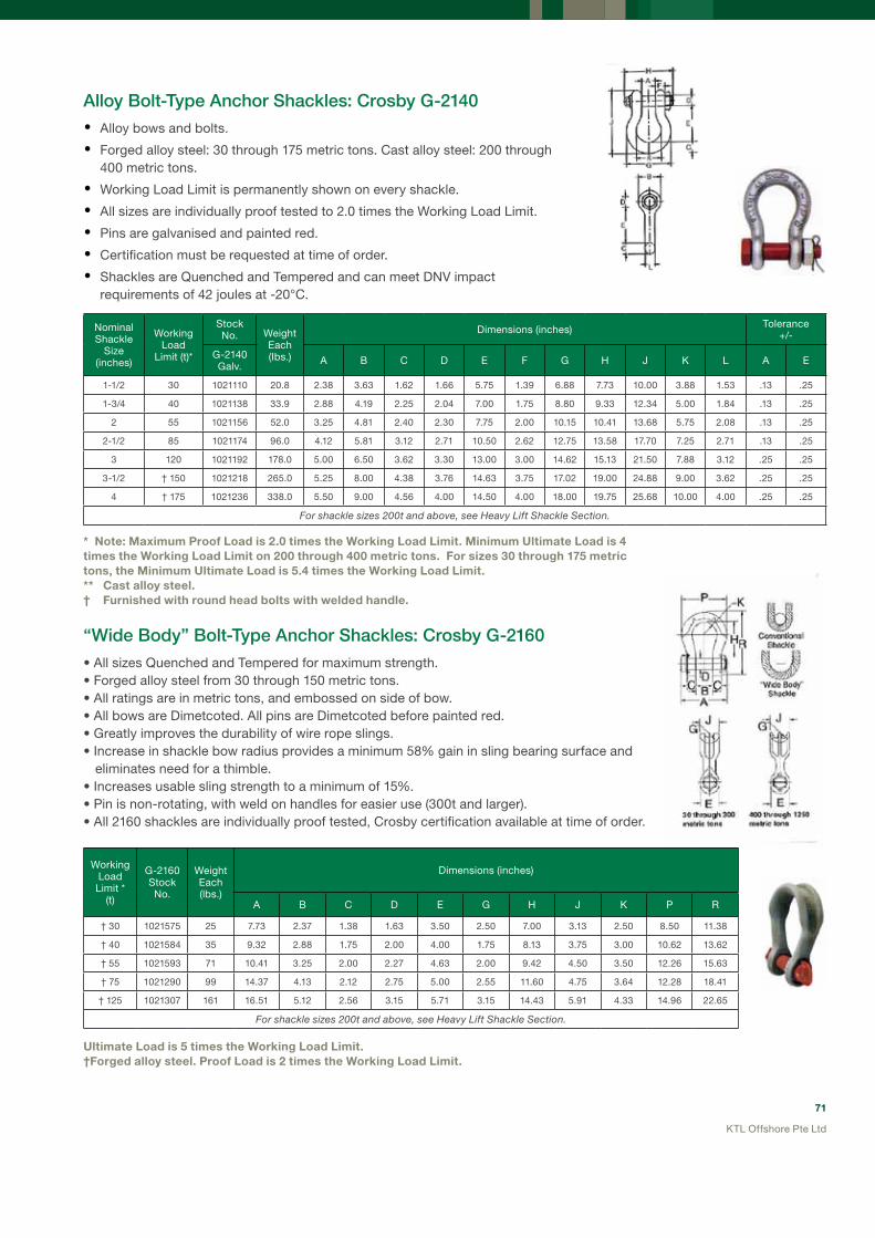
71
KTL Offshore Pte Ltd
Working Load Limit *
(t)
G-2160Stock No.
Weight Each(lbs.)
Dimensions (inches)
A B C D E G H J K P R
† 30 1021575 25 7.73 2.37 1.38 1.63 3.50 2.50 7.00 3.13 2.50 8.50 11.38
† 40 1021584 35 9.32 2.88 1.75 2.00 4.00 1.75 8.13 3.75 3.00 10.62 13.62
† 55 1021593 71 10.41 3.25 2.00 2.27 4.63 2.00 9.42 4.50 3.50 12.26 15.63
† 75 1021290 99 14.37 4.13 2.12 2.75 5.00 2.55 11.60 4.75 3.64 12.28 18.41
† 125 1021307 161 16.51 5.12 2.56 3.15 5.71 3.15 14.43 5.91 4.33 14.96 22.65
For shackle sizes 200t and above, see Heavy lift Shackle Section.
AlloyBolt-TypeAnchorShackles:CrosbyG-2140
• Alloy bows and bolts.
• Forged alloy steel: 30 through 175 metric tons. Cast alloy steel: 200 through 400 metric tons.
• Working Load Limit is permanently shown on every shackle.
• All sizes are individually proof tested to 2.0 times the Working Load Limit.
• Pins are galvanised and painted red.
• Certification must be requested at time of order.
• Shackles are Quenched and Tempered and can meet DNV impact requirements of 42 joules at -20°C.
* Note: Maximum Proof Load is 2.0 times the Working Load Limit. Minimum ultimate Load is 4 times the Working Load Limit on 200 through 400 metric tons. For sizes 30 through 175 metric tons, the Minimum ultimate Load is 5.4 times the Working Load Limit.** Cast alloy steel.† Furnished with round head bolts with welded handle.
“WideBody”Bolt-TypeAnchorShackles:CrosbyG-2160
• All sizes Quenched and Tempered for maximum strength. • Forged alloy steel from 30 through 150 metric tons. • All ratings are in metric tons, and embossed on side of bow. • All bows are Dimetcoted. All pins are Dimetcoted before painted red. • Greatly improves the durability of wire rope slings. • Increase in shackle bow radius provides a minimum 58% gain in sling bearing surface and eliminates need for a thimble. • Increases usable sling strength to a minimum of 15%. • Pin is non-rotating, with weld on handles for easier use (300t and larger). • All 2160 shackles are individually proof tested, Crosby certification available at time of order.
ultimate Load is 5 times the Working Load Limit. †Forged alloy steel. Proof Load is 2 times the Working Load Limit.
Nominal Shackle
Size (inches)
Working Load
Limit (t)*
Stock No. Weight
Each(Ibs.)
Dimensions (inches) Tolerance+/-
G-2140Galv. A B C D E F G H J K L A E
1-1/2 30 1021110 20.8 2.38 3.63 1.62 1.66 5.75 1.39 6.88 7.73 10.00 3.88 1.53 .13 .25
1-3/4 40 1021138 33.9 2.88 4.19 2.25 2.04 7.00 1.75 8.80 9.33 12.34 5.00 1.84 .13 .25
2 55 1021156 52.0 3.25 4.81 2.40 2.30 7.75 2.00 10.15 10.41 13.68 5.75 2.08 .13 .25
2-1/2 85 1021174 96.0 4.12 5.81 3.12 2.71 10.50 2.62 12.75 13.58 17.70 7.25 2.71 .13 .25
3 120 1021192 178.0 5.00 6.50 3.62 3.30 13.00 3.00 14.62 15.13 21.50 7.88 3.12 .25 .25
3-1/2 † 150 1021218 265.0 5.25 8.00 4.38 3.76 14.63 3.75 17.02 19.00 24.88 9.00 3.62 .25 .25
4 † 175 1021236 338.0 5.50 9.00 4.56 4.00 14.50 4.00 18.00 19.75 25.68 10.00 4.00 .25 .25
For shackle sizes 200t and above, see Heavy lift Shackle Section.

72
KTL Offshore Pte Ltd
Round pin shackles can be used in tie down, towing, suspension or lifting applications where the load is strictly applied in-line. No side loading is allowed.
Screw pin shackles can be used for applications involving side-loading circumstances. Reduced Working Load Limits are required for side-loading applications. While in service, do not allow the screw pin to be rotated by a live line, such as a choker application.
Application Information—Shackles
Bolt-type shackles are recommended for permanent or long term installations and where the load may slide on the shackle pin, causing the pin to rotate.
D-shaped shackles are used mainly for single leg slings whereas anchor shackles are used on multiple leg slings.
QUICK-CHECKMarkings
All Crosby shackles, except for G-2160, incorporate markings forged into the product at 45° from vertical. These allow a quick check on the approximate angle of a two-legged hitch or the angle of a single leg hitch when the shackle pin is secured. And the pull of the load is off vertical or side loaded, thus requiring a reduction in the working load limit of the shackle.
SideLoadingofShackles
Side Loading Reduction ChartFor Screw Pin and Bolt Type Shackles Only
Angle of Side Load from Vertical In-line of shackle
Adjusted Working Load Limit
0o In-line 100% of rated Working Load Limit
45o from In-line * 70% of rated Working Load Limit
90o from In-line * 50% of rated Working Load Limit
Crosby shackles may be side loaded. However, the shackle WLL must be reduced according to the table above.
CrosbyRangeOfGeneralLiftingShackles

73
KTL Offshore Pte Ltd
SLINGS AND FITTINGS FOR OFFSHORE CONTAINERSKTL Offshore And Crosby Bring The Highest Quality Rigging Equipment For The Most Demanding Conditions - Certified To DNv 2.7-1 Offshore Containers
CROSBY’S“OC-LIFTINGPRODUCT”RANGE
Crosby’s OC-Lifting Products for offshore containers is manufactured to DNV Type Approval under DNV 2.7-1 and a DNV Manufacturing Survey Agreement (MSA). In addition, each lot (identified by the PIC system) of shackles and links will be provided with a product certificate stating that the shackle/aster link has been manufactured and tested according to the Type Approval in a facility approved by the Manufacturing Survey Agreement.
A347OC
WhatAdvantagesDoesBuyingOffshoreContainerSlingsFromKTL OffshoreBringTheCustomer?
KTL Offshore value Added Features:
• Each individual and complete sling assembly is tested and certified to DNV 2.7-1 Offshore Containers by DNV Singapore.
• Crosby “OC-Lifting products” consists of master links, master link assemblies and shackles used exclusively in our OC Sling range.
• Sling WLL calculations done according to DNV 2.7-1 Offshore Containers, with verification and approval from DNV.
• The rigorous and demanding test procedure is strictly adhered to using specially adapted test machines and is witnessed by DNV Singapore.
CrosbyMasterLinkA-344OcAndMasterLinkAssemblyA-347Oc
• Individually proof tested 62.5% of Ultimate Strength as per DNV 2.7-1.
• Certified to meet Charpy impact testing of 31 ft-lbs. min. ave. at - 4 F (42J at -20 ºC).
• Marked with DNV type approval number.
• Crosby painted finish.

74
KTL Offshore Pte Ltd
MasterLinkA-347OC
MasterLinkAssemblyA344oc
CROSBYSHACKLESG-213OC
• Sample proof tested 40% of Ultimate Strength as per DNV 2.7-1.
• Certified to meet Charpy impact testing of 31 ft-lbs. min. ave. at - 4 F (42J at -20 ºC).
• Hot dip galvanized finish.
CrosbyShacklesG2130OC
Don’t accept low quality slings and fittings with questionable certification for your offshore containers- insist on KTL Offshore’s OC-Lifting Product range for peace of mind!
Size “A” A347OC Stock No.
Working Load Limit (t) Based on 4:1 Design Facor*
Proof Load (kN)
Ultimate Load (kN)
Dimensions (mm)
(mm) (inches) A B C D E F G31/25 1-1/4 1262957 17.0 416.9 667.1 31 145 275 25 210 115 13.5
40/31 1-9/16 1262966 23.6 578.8 926.1 40 160 300 31 270 140 15.5
54/36 1-3/4 1262975 31.5 773.0 1236 45 180 340 36 285 155 15.5
51/45 2 1262984 45.0 1104 1766 51 190 350 45 340 180 22.0
Size “A” A344OC Stock No.
Working Load Limit (t) Based on 4:1 Design Facor*
Proof Load (kN)
Ultimate Load (kN)
Dimensions (mm)
(mm) (inches) A B C31 1-1/4 1262774 16.0 392.4 627.8 31 145 275
40 1-9/16 1262792 25.0 613.1 981.0 40 160 300
45 1-3/4 1262797 31.5 784.8 1256 45 140 250
51 2 1262813 40. 981.0 1570 51 215 390
Nominal Shackle
Size (inches)
Working Load
Limit (t)*
Proof Load (kN)
Ultimate Load (kN)
G2130OC Stock No.
Weight Each (kg)
Dimensions (inch) Tolerance+/-
A B C D E F H L N C A
5/8 3-1/4 63.8 160 1262013 0.76 26.9 19.1 60.5 16.0 42.9 38.1 106 74.5 17.5 6.35 1.50
3/4 4-3/4 93.2 233 1262022 1.23 31.8 22.4 71.5 19.1 51.0 46.0 126 89.0 20.6 6.35 1.50
7/8 6-1/2 127.5 319 1262031 1.79 36.6 25.4 84.0 22.4 58.0 53.0 148 102 24.6 6.35 1.50
1 8-1/2 166.8 417 1262040 2.57 42.9 28.7 95.5 25.4 68.5 60.5 167 119 26.9 6.35 1.50
1-1/8 9-1/2 186.4 466 1262059 3.75 46.0 31.8 108 28.7 74.0 68.5 190 131 31.8 6.35 1.50
1-1/4 12 235.4 589 1262068 5.31 51.5 35.1 119 31.8 82.5 76.0 210 146 35.1 6.35 1.50
1-3/8 13-1/2 264.9 662 1262077 7.18 57.0 38.1 133 35.1 92.0 84.0 233 162 38.1 6.35 3.30
1-1/2 17 333.5 834 1262086 9.43 60.5 41.4 146 38.4 98.5 92.0 254 175 41.1 6.35 3.30
1-3/4 25 490.5 1226 1262095 15.40 73.0 51.0 178 44.5 127 106 313 225 57.0 6.35 3.30
* Minimum Ultimate Load is 5 times the Working Load Limit.

75
KTL Offshore Pte Ltd
RIGGING FOR SuBSEA ENGINEERINGKTL Offshore Has A Comprehensive Range Of Products And Services That Is Specifically Designed For Subsea Engineering
RemoteOperatedVehicle(ROV)ShacklesAndHooks
Crosby’s ROV friendly hooks and shackles are ideal for subsea engineering. The extensive range of designs prevents unauthorised alteration of standard subsea rigging equipment. This encourages the proper usage and lifespan of equipment.
G209R ROv ShackleAvailable up to 120t
L320R Eye HookAvailable up to 60t
L562R Shank HookAvailable up to 175t
The ROV product range:
• Designed for efficient handling and attachment of subsea and other hard-to-reach loads.
• Developed in conjunction with major North Sea subsea operators.

76
KTL Offshore Pte Ltd
CrosbyL562RShankHookQuenched and Tempered after welding is complete.
The eye size is designed to support rated capacity of up to 31.5t. Larger
models use a G-2140 shackle.
Painted fluorescent yellow (RAL 101) for enhanced underwater visibility.
The shank length was developed with the North Sea subsea operators.
Pad eyes on either side of hook allow use of stainless steel cable to open
the latch remotely.
The hook identification code is stamped on the hook.
QuIC-CHECK® indicators are forged on the top eye to show the maximum sling angle.
Hexagonal shank design allows easy grip by the robotic grip hand.
Heavy duty latch interlocks with the hook tip.
The unique tapered lead-in tip design allows easy engagement of eye bolts and pad eyes.
QuIC-CHECK® indicators (indicating maximum sling angle) and deformation indicators (for throat opening of hook) are forged on the hook.
* Minimum ultimate Load is 4 times the Working Load Limit. ** utilises Crosby G-2140 shackle as eye. † utilises Crosby S319N style hooks.
Features:
L562A Stock No.
Working Load
Limit (t)*
Hook ID
Code
WeighEach(kg)
Dimensions (mm) ReplacementLatch Stock
No.A B C D E F G H M N Q O R
1297722 † 5.4 IA 9.5 65 250 421 123 9.9 51 37 - 29 22 51 35 6.4 1096515
1297792 † 11.5 KA 15 65 250 518 192 30 76 57 - 41 32 76 53 9.7 1096609
1297806 † 16 LA 18 65 250 550 212 30 83 66 - 49 35 79 58 9.7 1096657
1297862 † 22 NA 31 85 250 608 263 45 108 76 - 60 40 91 77 19 1096704
1298042 31.5 OA 44 85 250 660 346 - 127 92 104 76 48 106 92 19 1090161
1298049 ** 37 PA 44 80 235 828 357 - 137 116 127 76 47 134 95 19 1090189
1298057 ** 45 SA 90 80 235 865 392 - 152 129 127 83 47 134 108 19 1090189
1298087 ** 60 TA 131 90 215 941 470 - 178 152 146 99 53 150 130 19 1090205
1298103 ** 100 WA 303 140 300 1185 584 - 173 218 184 140 69 190 124 19 1090241
1298117 ** 150 XA 395 150 230 1233 619 - 171 232 229 152 92 309 137 19 1090241
1298130 ** 175 YA 515 170 255 1326 678 - 191 248 254 178 102 300 - 19 -
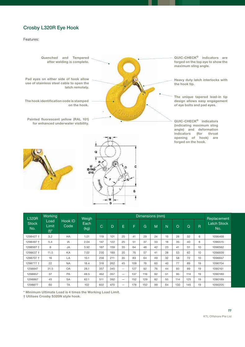
77
KTL Offshore Pte Ltd
L320R Stock No.
Working Load Limit (t)*
Hook IDCode
WeighEach(kg)
Dimensions (mm)ReplacementLatch Stock
No.C D E F G M N O Q R
1298427 † 3.2 HA 1.01 119 101 25 41 29 24 15 28 32 6 1096468
1298497 † 5.4 IA 2.04 147 122 25 51 37 33 18 35 40 6 1096515
1298567 † 8 JA 3.92 187 159 35 64 46 42 23 41 51 10 1096562
1298637 † 11.5 KA 7.02 230 189 35 76 57 41 28 53 62 10 1096609
1298707 † 16 LA 10.1 256 211 35 83 64 49 32 58 72 10 1096657
1298777 † 22 NA 18.4 318 262 45 108 76 60 40 77 89 19 1096704
1298847 31.5 OA 28.1 357 345 — 127 92 76 44 93 89 19 1090161
1298857 37 PA 48.5 462 357 — 137 116 92 51 95 114 19 1090189
1298867 45 SA 62.1 511 392 — 152 129 82 55 114 125 19 1090189
1298877 60 TA 102 602 470 — 178 152 99 64 130 145 19 1090205
* Minimum ultimate Load is 4 times the Working Load Limit. † utilises Crosby S320N style hook.
CrosbyL320REyeHook
Quenched and Tempered after welding is complete.
Pad eyes on either side of hook allow use of stainless steel cable to open the
latch remotely.
The hook identification code is stamped on the hook.
Painted fluorescent yellow (RAL 101) for enhanced underwater visibility.
QuIC-CHECK® indicators are forged on the top eye to show the maximum sling angle.
Heavy duty latch interlocks with the hook tip.
The unique tapered lead-in tip design allows easy engagement of eye bolts and pad eyes.
QuIC-CHECK® indicators (indicating maximum sling angle) and deformation indicators (for throat opening of hook) are forged on the hook.
Features:

78
KTL Offshore Pte Ltd
G209RStock No.
Working Load
Limit (t)*
WeightEach(kg)
Dimensions—Body (mm) Dimensions—Pin (mm)
A B C H L O F T S
1020872 6-1/2 1.79 36.6 25.4 84 148 102 50 58 10 17
1020902 8-1/2 2.28 42.9 28.7 95.5 167 119 50 61 10 18
1020932 9-1/2 3.75 46 31.8 108 190 131 70 83 12 18
1020952 12 5.31 51.5 35.1 119 210 146 70 84 12 23
1020972 13-1/2 7.18 57 38.1 133 233 162 75 91 15 23
1020992 17 9.43 60.5 41.4 146 254 175 75 93 15 24
1021102 25 † 15.4 73 51 178 313 225 90 114 17.5 29
1021125 35 † 24 83 57 197 348 253 106 132 20 30
1021158 55 † 45 105 70 267 453 327 120 145 25 45
CrosbyG209RRovShackle
Quenched and Tempered after welding is complete.
The identification code is stamped on the shackle.
An eye welded to the head of the shackle bolt for easy
grip by the robotic arm
QuIC-CHECK® indicators are forged on the bow to show the maximum sling angle.
Galvanised and painted fluorescent yellow (RAL 101) for enhanced underwater visibility. (17t and below)
Large safety pin allows easy grip by the robotic arm.
Pin is tapered for easy entry into the shackle and hitch point, and allows easy removal by the robotic arm.
Features:
* Minimum ultimate Load is 5 times the Working Load Limit.† Furnished with galvanised finish.
ROv shackles up to 120t can be made to order
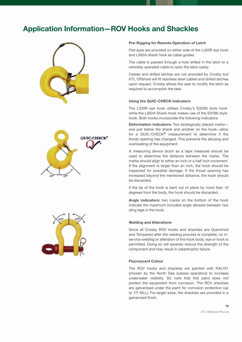
79
KTL Offshore Pte Ltd
Application Information—ROv Hooks and Shackles
Pre-Rigging for Remote Operation of Latch
Pad eyes are provided on either side of the L320R eye hook and L562A shank hook as cable guides.
The cable is passed through a hole drilled in the latch to a remotely operated cable to open the latch easily.
Cables and drilled latches are not provided by Crosby but KTL Offshore will fit stainless steel cables and drilled latches upon request. Crosby allows the user to modify the latch as required to accomplish the task.
using the QuIC-CHECK Indicators
The L320R eye hook utilises Crosby’s S320N style hook while the L562A Shank hook makes use of the S319N style hook. Both hooks incorporate the following indicators:
Deformation indicators: Two strategically placed marks—one just below the shank and another on the hook—allow for a QUIC-CHECK® measurement to determine if the throat opening has changed. This prevents the abusing and overloading of the equipment.
A measuring device (such as a tape measure) should be used to determine the distance between the marks. The marks should align to either an inch or a half-inch increment. If the alignment is larger than an inch, the hook should be inspected for possible damage. If the throat opening has increased beyond the mentioned distance, the hook should be discarded.
If the tip of the hook is bent out of plane by more than 10 degrees from the body, the hook should be discarded.
Angle indicators: two marks on the bottom of the hook indicate the maximum included angle allowed between two sling legs in the hook.
Welding and Alterations
Since all Crosby ROV hooks and shackles are Quenched and Tempered after the welding process is complete, no in-service welding or alteration of the hook body, eye or hook is permitted. Doing so will severely reduce the strength of the component and may result in catastrophic failure.
Fluorescent Colour
The ROV hooks and shackles are painted with RAL101 (chosen by the North Sea subsea operators) to increase underwater visibility. Do note that this paint does not protect the equipment from corrosion. The ROV shackles are galvanised under the paint for corrosion protection (up to 17t WLL). For larger sizes, the shackles are provided in a galvanized finish.

80
KTL Offshore Pte Ltd
KIMSPOOL 7 is able to accommodate the largest umbilical reels the offshore industry produces.
Using our experience gained in this segment of the market as well as consulting with our subsea engineering customers, KTL Offshore has designed a range of spooling equipment which is uniquely suitable for spooling of delicate umbilicals from the storage reel on to the winch. We also have specialist storage and transfer steel reels which ensures a smooth, tensioned application.
Our Kimspool machines have constant tension ability and we have performed many successful umbilical spooling jobs for our subsea engineering customers.
KTL Offshore umbilical Spooling Features:
• Specialised transfer and installation steel reels designed for umbilical cords
• Constant tension spooling
• Accommodate reel weights up to 200 metric tons with 20t constant back tension
• A fleet of rugged spooling machines
• Experienced technical services personnel
umbilical Spooling

81
KTL Offshore Pte Ltd
12x12strand12strand
SyNTHETIC ROPESFOR OFFSHORE CONSTRuCTIONHigh Performance Synthetic Rope (HMPE) High Modulus PolyEthylene Ropes from Cortland Puget Sound Rope, USA
Plasma–TheWorld’sStrongestSyntheticRope!
Plasma – the highest strength-to-mass-ratio of any rope available, this 12 strand or 12x12 strand constructions offers equivalent strength to a wire rope of the same size. Elongation is similar to wire rope. The patented 12x12 construction is easily repaired in the field by replacing any damaged strands and the Plasma rope is probably the easiest rope to splice on-site. A Polyurethane coating increases abrasion resistance while the rope is UV stabilized and creep properties are negligible at working loads. Made from Honeywell’s Spectra fiber and heat treated using PSR’s recrystallization process.
• Elongation 4-5% at breaking load for a new rope (2-3% for a worked rope).
• Critical temperature 65 Deg C (150 Deg F) • Torque free construction. • Coefficient of friction 0.09-0.12. • Specific gravity 0.98 (floats). The formulation can be altered to change the specific gravity to make the rope sink if required (specify at time of order with the factory).
• Applications:- Winch lines.- Tugger winch lines.- Pick up and messenger lines.- Heavy lift slings where the higheststrength-to-mass ratio and torque free properties are required.
Spectra-HighStrengthwithAddedElongation!
Spectra – a slightly lower strength than the Plasma rope, Spectra has the same outstanding abrasion, UV and creep resistant properties. The rope construction is the same 12 or 12x12 strand as the Plasma. Spectra will be selected if more elasticity is required, as the elongation properties are slightly higher than those of the Plasma rope.
• Elongation 6-8% at breaking load for a new rope (3-4% for a worked rope).
• Critical temperature 65 Deg C (150 Deg F). • Torque free construction. • Coefficient of friction 0.09-0.12. • Specific gravity 0.98 (floats). • Applications:- Winch lines.- Single/Split drum winch primary mooring lines.- Tugger winch lines.- Pick up and messenger lines.- Heavy lift slings where the higher elongation
and elasticity is required.

82
KTL Offshore Pte Ltd
Jacketed,HighStrengthHMPERope
High strength ropes using either Plasma or Spectra rope as the core, encased in a protective jacket increases the abrasion resistance of the rope while maintaining the high strengths offered by HMPE fibers.
The outer jacket is tightly woven but has a looser fit over the core rope than a regular double braided rope and does not contribute to the strength. This creates the distinct advantage of not having to retire the rope if cuts and abrasion damage occurs to the jacket.
G/T composite Double braid – this is a Plasma rope encased in a tightly braided jacket of Spectra to offer the highest abrasion resistance and durability. They are suitable where a very high strength, firm, round and torque-free rope is required.
• Elongation 4-5% at breaking load for a new rope (2-3% for a worked rope).
• Critical temperature 65 Deg C (150 Deg F). • Torque-free construction. • Coefficient of friction 0.12 – 0.15. • Specific gravity 0.98 (floats).
• Applications:- Heavy duty winch line where the
most rugged duty is expected.- Single/Split drum winch primary
mooring lines.
D/T composite Double braid – this is a Plasma rope encased in a tightly braided jacket of polyester. The polyester does not have the abrasion resistance of the Spectra jacket but does offer a softer feel to the rope.
• Elongation 4-5% at breaking load for a new rope (2-3% for a worked rope).
• Critical temperature 65 Deg C (150 Deg F). • Torque-free construction. • Coefficient of friction 0.12 – 0.15. • Specific gravity 0.98 (floats).
• Applications:- Heavy duty winch lines.- Single/Split drum winch primary
mooring lines.
D/S composite Double braid – this is a Spectra rope encased in a tightly braided jacket of polyester which gives the feel and handling of a polyester double braid rope. This rope will give a much higher strength than the polyester double braid due to the Spectra core while still providing the protection of an outer jacket.
• Elongation 4-5% at breaking load for a new rope (2-3% for a worked rope).
• Critical temperature 65 Deg C (150 Deg F). • Torque-free construction. • Coefficient of friction 0.12 – 0.15. • Specific gravity 1.20 (sinks)
• Applications:- Heavy duty winch lines.- Single/Split drum winch primary
mooring lines.

83
KTL Offshore Pte Ltd
Summary of Comparative Properties
applications – Offshore WinchAll of the PSR ropes mentioned here are suitable for general offshore winch duties including mooring, anchoring, towing, lifting and holding.
Key PropertyHighest Strength-to
Weight Ratio (Low Elongation)
Maximum Abrasion Resistance(Jacketed Rope)
Polyester, Higher Elongation
ProductsPlasma
12 Strand
Spectra 12
Strand
G/T Composite
(Spectra Jacket/Plasma Core)
D/T Composite(Polyester
Jacket/Plasma Core)
D/S Composite(Polyester
Jacket/Spectra Core)
Polyester Double Braid
Polyester 12-Plait
Braided Polyester Parallel Core
Strength Highest High High High High Moderate ModerateModerate to
high
Elongation at break
(new rope)4% - 5% 6% - 8% 4% - 5% 4 % - 5% 6% - 8% 15% - 20% 15% - 20% 13% - 18%
Bending Fatigue
High High High High High Moderate Moderate Moderate
Specific Gravity(kg/dm3)
0.98 0.98 0.98 1.20 1.20 1.38 1.38 1.38
Floats in Water
Yes Yes Yes No No No No No
Critical Temperature
650C 650C 650C 650C 650C 1770C 1770C 1770C
UV Resistance
Moderate Moderate Excellent Excellent Excellent Excellent Excellent Excellent
Abrasion Resistance
Superior Superior Superior Superior Superior Excellent Excellent Excellent
Fiber Water Absorption
0% 0% 0% to 1% 0% to 1% 0% to 1% 0% to 1% 0% to 1% 0% to 1%
RemarksHighest
strength to
weight ratio
High
strength
with slightly
more
elongation
Braided outer cover provides superior abrasion
resistance. Round, firm rope construction
Higher
abrasion
resistance
than 12 plait
polyester
Easily
inspectable,
low cost
Best suited
to mooring
in a static
application

84
KTL Offshore Pte Ltd
TechnicalInformationAndTestData
Elongation characteristics of Plasma Rope
The graph on the left shows the elongation characteristics of the Plasma rope in the new condition.
A worked rope will demonstrate less elongation (maximum 2-3% at breaking load).
% E
long
atio
n
Load (% of average strength)
3
5
6
9
12
15
18
10 15 20 25 30 35
ELOnGaTIOn (%)PLASMA ELONGATION
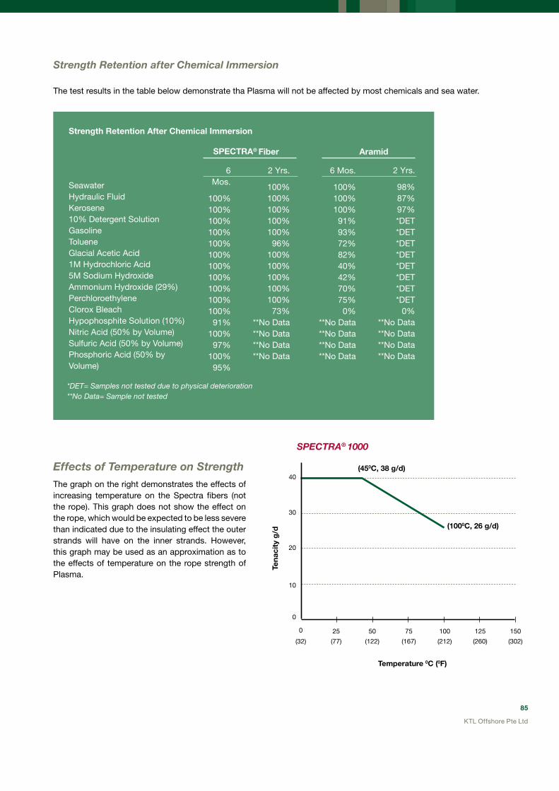
85
KTL Offshore Pte Ltd
Strength Retention after chemical Immersion
Effects of Temperature on StrengthThe graph on the right demonstrates the effects of increasing temperature on the Spectra fibers (not the rope). This graph does not show the effect on the rope, which would be expected to be less severe than indicated due to the insulating effect the outer strands will have on the inner strands. However, this graph may be used as an approximation as to the effects of temperature on the rope strength of Plasma.
*deT= Samples not tested due to physical deterioration**No data= Sample not tested
SeawaterHydraulic FluidKerosene10% Detergent SolutionGasolineTolueneGlacial Acetic Acid1M Hydrochloric Acid5M Sodium HydroxideAmmonium Hydroxide (29%)PerchloroethyleneClorox BleachHypophosphite Solution (10%)Nitric Acid (50% by Volume)Sulfuric Acid (50% by Volume)Phosphoric Acid (50% by Volume)
6 Mos.
100%100%100%100%100%100%100%100%100%100%100%91%
100%97%
100%95%
6 Mos.
100%100%100%91%93%72%82%40%42%70%75%0%
**No Data**No Data**No Data**No Data
2 Yrs.
100%100%100%100%100%96%
100%100%100%100%100%73%
**No Data**No Data**No Data**No Data
2 Yrs.
98%87%97%*DET*DET*DET*DET*DET*DET*DET*DET
0%**No Data**No Data**No Data**No Data
SPECTRA® Fiber Aramid
The test results in the table below demonstrate tha Plasma will not be affected by most chemicals and sea water.
SPEcTRa® 1000
Temperature 0C (0F)
(450C, 38 g/d)
(1000C, 26 g/d)
Tena
city
g/d
10
0
0 25
(32) (77) (122) (167) (212) (260) (302)
20
30
40
50 75 100 125 150
Strength Retention After Chemical Immersion

86
KTL Offshore Pte Ltd
At room temperature the effects of creep as a function of applied load are indicated in the graph below.
creep Effects The creep effect (whereby when the material is held under load it will elongate over a period of time) on the Spectra fibers is shown in the graphs below. At low temperatures the effect is very small while at elevated temperature, creep does become noticable.
Time (Hrs)
SPECTRA® S-1000% E
long
atio
n
0.0
12.0
6.0
18.0
2.0
14.0
8.0
20.0
4.0
16.0
10.0
0 50 100 150 200 250
Creep at 10% Load500C (1220F)
Time (Hrs)
SPECTRA® S-1000% E
long
atio
n C
reep
0.6
0.4
1
1.2
0.2
0
0.8
0 10 8020 10030 12040 14060 160
Creep at 20% Load500C (410F)
SPEcTRa® S-1000Room Temperature Creep
20% Load
15% Load
10% Load
% E
long
atio
n
12
6
18
2
0
14
8
20
4
16
10
1000 200 300 400 600500 700
Time (Hrs)
Note: Test conducted on 1300d S-1000 fiber

87
KTL Offshore Pte Ltd
Fatigue LifeThe graph below shows the comparative fatigue life of a Spectra 12 strand, single braided rope against some other common synthetic ropes. The test results demonstrate clearly the superior fatigue life of the rope made of the Spectra fiber.
(All ropes 1.5” Diameter)
8,03825,256 29,130 37,140
48,534
250,000
Str
oke
to
Fai
lure
50,000
200,000
0
Polyproylene Plaited
Poly-Polyester Combo
Polyester Single Braid
Polyester Double Braid
Nylon 3-Strand
Spectra Single Braid
100,000
250,000
150,000
300,000
Rope Construction
Diameter Diameter Circ. Weight Spliced MBLISO BS EN
2307: 2010 MBL
mm inches mm kg/100m (Metric Tons) (Metric Tons)
12 Strand
1.0 0.04 2.9 0.1 0.1 0.1
1.25 0.05 3.6 0.1 0.2 0.2
1.5 0.06 4.3 0.1 0.2 0.2
1.75 0.07 5 0.2 0.3 0.4
2.5 0.1 7.2 0.4 0.6 1
3.0 1/8 9 0.8 1.3 2
5 3/16 13.5 1.7 2.5 3
6 1/4 18 2.4 3.6 4
8 5/16 22.5 3.7 5.3 6
9 3/8 27 5.5 7.9 9
11 7/16 30 6.3 9.5 11
12 1/2 36 9.5 14.2 16
14 9/16 42 11.8 17.2 19
16 5/8 48 15.8 23.3 26
18 3/4 54 19.8 31.1 34
20 13/16 60 23.7 33.6 37
22 7/8 66 29.2 42 46
24 1 72 34.8 49.9 55
26 1-1/16 78 40.9 58.6 65
28 1-1/8 84 47.5 66.7 74
30 1-1/4 90 53.9 74.8 83
32 1-5/16 96 62.1 88.9 98
36 1-1/2 108 76.9 100.2 111
Plasma 12 Strand Rope Data – Up to 4” (102mm) Diameter
Rated Minimum Breaking Load

88
KTL Offshore Pte Ltd
Rope Construction
Diameter Diameter Circ. Weight Spliced MBLISO BS EN
2307: 2010 MBL
mm inches mm kg/100m (Metric Tons) (Metric Tons)
12x12 Strand
40 1-5/8 120 97.8 131.9 146
44 1-3/4 132 116.7 142.4 158
48 2 144 136 161.0 178
52 2-1/8 156 162.2 194.1 215
56 2-1/4 168 181.6 218.1 242
60 2-1/2 180 220.2 240.3 267
64 2-5/8 192 248.5 270.2 300
68 2-3/4 204 278.3 299.3 332
72 3 216 318.5 353.7 393
76 3-1/8 228 349.7 385.4 428
80 3-1/4 240 388.4 426.2 473
88 3-5/8 264 482.2 566.8 629
96 4 288 586.4 689.2 765
Rope Construction
Diameter Diameter Circ. Weight Spliced MBLISO BS EN
2307: 2010 MBL
mm inches mm kg/100m (Metric Tons) (Metric Tons)
12x12 Strand
98.4 4.1 309.6 723 735 816
103.2 4.3 321.6 768 776 862
103.2 4.3 326.4 813 817 908
108 4.5 338.4 856 858 953
110.4 4.6 350.4 902 898 998
112.8 4.7 357.6 957 939 1043
117.6 4.9 369.6 1014 980 1089
120 5 381.6 1073 1021 1134
124.8 5.2 393.6 1136 1062 1180
129.6 5.4 405.6 1197 1103 1226
132 5.5 417.6 1256 1143 1270
139.2 5.8 441.6 1397 1225 1361
144 6 453.6 1485 1266 1470
146.4 6.1 465.6 1579 1307 1452
151.2 6.3 477.6 1671 1348 1498
156 6.5 494.4 1765 1388 1542
160.8 6.7 506.4 1860 1429 1588
165.6 6.9 523.2 1973 1470 1633
172.8 7.2 542.4 2104 1511 1678
177.6 7.4 559.2 2244 1552 1724
182.4 7.6 578.4 2392 1593 1770
189.6 7.9 595.2 2539 1633 1814
Large Diameter Plasma 12 Strand Rope - 104mm and above
Note:• All MBL values shown include provision of a 0.90 splicing efficiency. When spliced using a standard synthetic rope splicing
method, no further de-rating of the rope MBL is required.• For use in basket hitch, the full strength will be attained at a D/d = 3.0 or higher.• MBL and SWL figures provided above are in accordance with the Cordage Institute CI-1500-02 (May 2006) from the USA which
reports the strength as “spliced strength”. According to BS EN ISO 2307:2010, theses figures can be increased by 10% as the splicing efficiency is not factored in to the rated strength using this European standard.

89
KTL Offshore Pte Ltd
KTL Offshore value Added:
Composite Ropes offer several advantages over Polypropylene ropes:
• Higher strength therefore a lighter and smaller diameter rope can be used
• Greater abrasion resistance
• Superior Ultra Violet (U.V.) resistance which leads to longer life
• Improved fatigue life and ability to withstand the harsh offshore environment
TITAN – one of the strongest ropes available on the market!
Titan is an advanced, plaited 8-strand rope with one of the highest tensile strengths available on the market. Due to the polyester filaments on the surface of the rope, it has excellent abrasion resistance. Titan ropes are suitable for the harshest offshore environments. Does not float on water.
CRuISER – Excellent strength-to-mass ratio!
Cruiser has a very high strength as compared to polypropylene ropes and superior abrasion resistance properties. It is highly U.V. stabilized leading to long life in the offshore environment. Very good selection as a replacement for PP ropes to reduce weight, size and overall cost. Floats on water.
All LANEX ropes are supplied with soft eyes with canvas protection at both ends, 6-tuck splicing, colour tracers and Germanischer Lloyd’s (GL) or Lloyd’s Register (LR) certification.
KTLOffshoreOffersTheFollowing8-StrandPlaitedComposite RopesFromLanex(MadeInEurope):
Standard Synthetic Rope Composite, Polypropylene And Nylon Rope

90
KTL Offshore Pte Ltd
KTLOffshoreStocksAHugeRangeOfNylonAndPolypropyleneRopesFromTheKoreanManufacturesSuchAsDSR,DongYangAndManho.
100% Nylon Ropes – Excellent Shock absorbing ability!
Nylon ropes have very high strength and have excellent shock absorbing properties due to their high elasticity. Nylon also has good abrasion resistance and is not damaged by oil and most chemicals. U.V. stability is good. Nylon ropes do not float in water.
Polypropylene (PP) Ropes – All purpose synthetic rope!
Polypropylene ropes are very light in weight and therefore float on water and are popular in the industry due to their low cost. They have excellent resistance to most chemicals but are affected by sunlight (poor U.V. resistance and it is best to store them out of direct sunlight).
KTL Offshore stocks Superdan (DSR), Mega PP (Dong Yang) and Hi-Man (Manho) polypropylene ropes.
All Nylon and PP ropes are supplied with soft eyes with canvas protection at both ends, 6-tuck splicing, colour tracers and Lloyd’s Register (LR) certification.

91
KTL Offshore Pte Ltd
Application And Properties Table: 8-Strand Plaited Synthetic Rope
Type of Rope POLYPROPYLENE NYLON LANEX CRUISER LANEX TITAN
Composite Material HDPP split film 100% Nylon20% PES
80% Polys50% PES
50% Polys
SpecificDensity: 0.91kg/dm3 1.14kg/dm3 0.99kg/dm3 1.14kg/dm3
FloatsOnWater: Yes No Yes No
WaterAbsorbtion: None 2% to 5% None 2% to 5%
MeltingPoint: 1650C 2150C 165/2600C 165/2600C
MaximumWorkingTemperature:
800C 1000C 1000C 1000C
ElongationAtMBL:New Rope: 15%
Worked Rope: 12%New Rope: 35%
Worked Rope: 25%New Rope: 15%
Worked Rope: 12%New Rope: 15%
Worked Rope: 12%
UVStability: Good Very Good Very Good Excellent
AbrasionResistance: Good Very Good Very Good Excellent
ChemicalResistance: Very Good Average Very Good Good
Durability: Good Excellent Very Good Excellent
Handling: Good Very Good Very Good Excellent
*TCLLValue(%ofMBL): 52% 55% 78% 78%
TypicalApplication:
General all-purpose rope for marine and offshore use.Example: Mooring lines; messenger lines; pickup lines & towing.
Tails on wire rope; Towing & towing stretchers; any application where high elasticity is required.
Mooring and towing lines, messenger and pick-up lines. For Anchor Handling Vessel use in demanding conditions. Composite ropes offer a higher performance option than PP or Nylon ropes due to their superior abrasion, chemical resistance and fatigue properties. Titan ropes offer the best heavy duty performance followed by Cruiser
PES: high tenacity polyesterPolys: 30% HDPE (Polyethylene) and 70% HDPP (polypropylene)*TCLL value: the load expressed as a % of the breaking strength at which the rope will fail at 1000 cycles in a tension-fatigue test.
Rope Diameter
Circ.POLYPROPYLENE (PP) NYLON (100%)
LANEX CRUISER Composite Rope
LANEX TITANComposite Rope
Weight MBL Weight MBL Weight MBL Weight MBL
(mm) (inches) (kg/100m)(metric tons)
(kg/100m)(metric tons)
(kg/100m)(metric tons)
(kg/100m)(metric tons)
3640444852
4-1/25
5-1/26
6-1/2
58.672.387.5
104.0122.0
2326313642
78.095.0120.0141.0166.0
2433414655
64.679.296.8114.4134.2
2633394653
78.797.5117.5139.5164.0
3042505968
566064
77-1/2
8
142.0163.0185.0
485562
191.0221.0235.0
617180
156.2179.3203.5
616978
190.5219.0249.0
8090102
687276
8-1/29
9-1/2
210.0234.0262.0
707784
285.0316.0346.0
9099108
231.0257.4288.2
8898110
283.0317.035.0
115128143
808896
101112
289.0350.0417.0
95107135
385.0471.0545.0
122146169
319.0386.1458.7
121145171
391.5474.0563.0
157188221
104112120130
13141516
489.0627.0715.0
157183208
666.0750.0800.0889.0
200210256300
Data provided upon application
Minimum Breaking Load: 8-Strand Plaited Synthetic Rope

92
KTL Offshore Pte Ltd
BLOCKS FOR OFFSHORE CONSTRuCTIONKTL Offshore Provides High Quality Snatch Blocks From The uSA And Europe For The Most Demanding Offshore Applications
SnatchBlockSelectionGuide
Use the following guide to select the right snatch blocks for offshore construction:
Main Requirement
Durability and Cost Efficiency
Reduced Weight and High Strength
High Working Load Limit
Increased Work Efficiency for Specific Tasks
KTL Offshore value Added Features For Snatch Blocks:
• Full Range Inventory
KTL Offshore maintains one of the largest and most comprehensive range of McKissick snatch blocks.
• Product Training
Through Crosby, KTL Offshore provides specific product training on snatch blocks and their use, inspection and maintenance.
• Inspection, Testing and Certification
Call our qualified inspectors to perform the required in-service inspection, testing and certification of all your snatch blocks.
• Refurbishment
We provide assisting services like stripping down, reworking and reassembling the block before testing and certification.
• Custom Made
We are able to customise your snatch blocks to meet every demand.
McKissick’s Light Champion, Champion, Super Champion and Double Sheave Light Champion Range (Made in the uSA)
McKissick’s Alloy Range
(Made in the uSA)
High WLL Heavy Duty Blocks(Up to 1,000 WLL)
(Made in Holland)
Specialised Blocks by KTL Offshore:Underwater blocks and customdesigned blocks (Made in the uSA and Holland)

93
KTL Offshore Pte Ltd
SheaveDiameter(inches)
BearingCode
Stock No.Wire RopeSize
(inches)
WorkingLoadLimit
(metric tons)*
Weight Each(Ibs.)
420(with
Hook)
421 (with
Shackle)
406(with Tail
-board)
420(with
Hook)
421(with
Shackle)
406(with Tail
-board)
6 BB 169374 169481 1679733/4 -7/8
12 40 48 24
6 RB 169392 204120 1679823/4 -7/8
12 40 48 24
8 BB 169418 169515 1679913/4 -7/8
15 51 57 30
8 RB 169445 204193 1680083/4 -7/8
15 51 57 30
10 BB 110221 110720 1031863/4 -7/8
15 63 69 42
10 RB 110258 110757 1032023/4 -7/8
15 63 69 42
McKissick Snatch Blocks—Regular useThe Most Popular Brand Of Snatch Blocks In The World: McKissick
LightChampionRange:2TTo15TWll
* ultimate Load is 4 times the Working Load Limit.** Available in bronze bushed only. 3” and 4-1/2” types have self-lubricating bronze bushing. † Fitted with 1-1/4” I D swivel eye.†† May be furnished in other wire rope sizes.
Type 418 (with hook)
Type 404 (with
tailboard)
Type 419 (with
shackle)
ChampionRange:12TTo15TWLL
*ultimate Load is 4 times theWorking Load Limit.
†May be furnished in other Wire Rope sizes.
Type 420 (with hook)
Type 406 (with
tailboard)
Type 421 (with
shackle)
SheaveDiameter(inches)
BearingCode
Stock No. Wire RopeSize
(inches)
WorkingLoadLimit
(metric tons)*
Weight Each(Ibs.)
418(with
Hook)
419 (with
Shackle)
404(with Tail -board)
418(with
Hook)
419(with
Shackle)
404(with Tail -board)
* 3 BB — 109091 —5/16-3/8
2 — 4 —
** 3 BB 108038 109037 1020165/16-3/8
2 5 4 3
** 4-1/2 BB 108065 109064 1020253/8 -1/2
4 12 12 7
66
BBRB
108127108154
109126109153
102098102114
3/8 - 1/2
88
2727
2828
1515
88
BBRB
108225108252
109224109251
102169102187
5/8 -3/4
88
3333
3434
2121
1010
BBRB
108323108350
109322109359
102230102258
5/8 -3/4
88
4141
4242
2929
1212
BBRB
169169199911
202961169347
178890178934
5/888
4848
4949
3636
1212
BBRB
108421108458
109420109457
102301102329
3/488
4848
4949
3636
1414
BBRB
194920199948
169356167857
——
5/888
5555
5656
——
1414
BBRB
108528108546
109527109545
——
3/488
5555
5656
——
1616
BBRB
199975200008
203041203087
——
3/41515
130130
135135
——
1616
BBRB
108608108626
109607109625
——
7/81515
130130
135135
——
1818
BBRB
200099200151
203130203176
——
7/81515
150150
155155
——
1818
BBRB
108644108662
109643109661
——
11515
150150
155155
——
Single sheave for 3⁄4” to 7/8” wireline.
Single sheave for 5/16” to 1” wireline.
94
KTL Offshore Pte Ltd
*ultimate Load is 4 times the Working Load Limit.
†May be furnished in other Wire Rope sizes.
Type 408(with Hook)
Type 409(with Shackle)
Sheave
Diameter
(inches)
Bearing
Code
Stock No.
Wire Rope
Size
(inches)
Working
Load
Limit
(metric
tons)*
Weight Each
(Ibs.)
430
(with
Hook)
431
(with
Shackle)
407
(with
Tail
-board)
430
(with
Hook)
431
(with
Shackle)
407
(with Tail
-board)
8 BB 120023 121022 103523 1-1/8 20 75 87 42
8 RB 120041 121040 103541 1-1/8 20 75 87 42
10 BB 120096 121095 103603 1-1/8 20 89 101 55
10 RB 120112 121111 103621 1-1/8 20 89 101 55
12 BB 208536 169917 184375 1 20 103 115 70
12 RB 208554 209303 184393 1 20 103 115 70
12 BB 120176 121175 103685 1-1/8 20 103 115 70
12 RB 120194 121193 184419 1-1/8 20 103 115 70
14 BB 208572 209321 184437 1 20 123 135 90
14 RB 208590 170424 103765 1 20 123 135 90
14 BB 1201256 121255 103783 1-1/8 20 123 135 90
14 RB 120274 121273 184552 1-1/8 20 123 135 90
18 BB 208689 209410 184605 1 25 240 260 165
18 RB 208732 209465 119641 1 25 240 260 165
18 BB 119482 119561 119650 1-1/8 25 240 260 165
18 RB 119491 119570 184 1-1/8 25 240 260 165
20 BB 208750 209483 184623 1-1/8 30 375 400 215
20 RB 208787 169864 184650 1-1/8 30 375 400 215
20 BB 119507 119589 119669 1-1/4 30 375 400 215
20 RB 119516 119598 184678 1-1/4 30 375 400 215
24 BB 208812 209526 184687 1-1/8 30 450 475 290
24 RB 208858 209553 184721 1-1/8 30 450 475 290
24 BB 119525 119605 119687 1-1/4 30 450 475 290
24 RB 119534 119614 119696 1-1/4 30 450 475 290
SuperChampionRange:20TTo30TWLL
*ultimate Load is 4 times the Working Load Limit.†May be furnished in other Wire Rope sizes.
DoubleSheave—LightChampionRange:4Tto12TWLLDouble sheaves for 3/8” to 3/4” wireline.
Type 430 (with Hook)
Type 431(with shackle)
Type 407(with Tailboard)
Sheave
Diameter
(inches)
Bearing
Code
Stock No.Wire Rope
Size
(inches)
Working
Load
Limit
(metric
tons)*
Weight Each
(Ibs.)
408
(with Hook)
409
(with
Shackle)
408
(with
Hook)
409
(with
Shackle)† 4-1/2 BB 104023 105022 3/8 - 1/2 4 18 18
6 BB 104103 105102 5/8 - 3/4 12 45 50
6 RB 104121 105120 5/8 - 3/4 12 45 50
8 BB 104185 105184 5/8 - 3/4 12 53 58
8 RB 104201 105200 5/8 - 3/4 12 53 58
10 BB 104265 105264 5/8 - 3/4 12 70 75
10 RB 104283 105282 5/8 - 3/4 12 70 75
12 BB 194578 195185 5/8 12 90 95
12 RB 168044 195229 5/8 12 90 95
12 BB 104345 105344 3/4 12 90 95
12 RB 104363 105362 3/4 12 90 95
14 BB 194621 195247 5/8 12 100 105
14 RB 194649 195265 5/8 12 100 105
14 BB 104425 105424 3/4 12 100 105
14 RB 104443 105442 3/4 12 100 105
Single sheave for 1” to 1-1/4” wireline.

95
KTL Offshore Pte Ltd
AllAlloyRange:12TWLL
Sheave Diameter (inches)
Bearing Code
Stock No.Wire Rope Size
(inches)
Working Load Limit
(metric tons)*
Weight Each (lbs.)
416 Alloy with
Hook
417 Alloy with
Shackle
402 Alloy Tail
Board
416 Alloy with Hook
417 Alloy with
Shackle
402Alloy Tail
Board
6 BB 193427 168972 179238 3/4 - 7/8 12 26 27 15
6 RB 193472 193757 179283 3/4 - 7/8 12 26 27 15
8 BB 193490 168990 179316 3/4 - 7/8 12 33 34 21
8 RB 193542 163819 179363 3/4 - 7/8 12 33 34 21
10 BB 193614 193882 179434 3/4 - 7/8 12 41 42 29
10 RB 193677 193935 179498 3/4 - 7/8 12 41 42 29
Type 416- with Hook
Type 417-with Shackle
Type 402-with Tailboard
* ultimate Load is 4 times the Working Load Limit.† May be furnished in other wire rope sizes.
High WLL Heavy Duty (HD) Snatch BlocksManufactured In Holland, KTL Offshore’s Range Of Heavy Duty Snatch Blocks Extends up To 1,000 Metric Tons WLL!
Ropeblock BV and their subsidiary Van Mechelen BV manufacture heavy duty snatch blocks to KTL Offshore’s specification – designed for the harsh offshore environment, built to last.
Snatch blocks can be custom made to suit your requirements and are supplied with material, proof load and third party test certification (upon request).
Used by the world’s foremost offshore contractors, our heavy duty snatch blocks have a proven track record for reliability and ruggedness.
Part No
WLL
(metric
tons)
Wire
Rope
Diameter
(mm)
Wire Rope
Diameter
(inches)
Dimensions (mm) Weight
D1 D2 T Q R TA TB TL (kg)
RKTL 851 85 52 2 855 725 120 87 27 175 870 1750 1000
RKTL 1201 120 52 2 855 725 135 102 27 195 870 1890 1300
RKTL 1501 150 64 2-1/2 920 770 150 115 35 220 935 2000 1600
RKTL 2001 200 76 3 1115 910 160 138 41 260 1130 2200 2400
RKTL 2501 250 82 3-1/4 1300 1080 185 149 44 280 1315 2500 3750
RKTL 3001 300 90 3-1/2 1500 1260 190 160 48 310 1515 2850 4800
RKTL 4001 400 102 4 1860 1550 210 185 55 310 1880 3860 7500
RKTL 5001 500 114 4-1/2 2115 1824 235 198 61 330 2135 4250 10500
RKTL 6001 600 127 5 2225 1905 260 215 68 350 2245 4500 12000
HDRangeOfSnatchBlocks
DF = 4:1Wireline sizes and sheave sizes can be altered to suite your requirements.Other combinations of wire line size and WLL available.
Single sheave for 3/4” to 7/8” wireline.All Alloy Range – High Strength, Low WeightWeight is only 60% of regular block of same WLL!

96
KTL Offshore Pte Ltd
Crane Blocks, Construction Blocks and SheavesMcKissick Makes The Largest Blocks For The Offshore Industry
ForOffshoreCranes:The380Series
The McKissick 380 Utility Crane Block series is an industry standard and equips some of the largest derrick barges in the world.
It comes in one to eight sheave configurations, with more designs available upon request.
Features:
• Tapered Roller Bearings (other types can be used but TRB is recommended for offshore use).
• Dual action hooks: swings and rotates.
• Anti-rotation locking device (75t and larger).
• Plate steel cheek weights.
Available hook types:
McKissick value Added Features For Crane And Construction Blocks:
• Manufactured in the USA at McKissick’s API Q1 certified factory.
• Crane blocks can be custom made to meet every demand.
• Repair parts are available for all block models.
• Roll forged sheaves are used as standard in all crane blocks.
SiNGLe (for loads up to 300t)
DuPLex(for loads up to 1000t)
QuaD(for loads 200t and above)
ForMobileCranes:TheM780Series
For mobile cranes, the M780 series Metric Crane Block has been designed with a maximum WLL of 75 metric tons.
Features:• Size of wire line range from 12 to 29mm.
• Sheaves can be grooved for metric or imperial dimensions (or both).
• Dual action hooks: swings and rotates.
• Available with 1, 2 or 3 sheaves.
• Supplied with sealed roller bearings.
97
KTL Offshore Pte Ltd
underwater BlocksDepend On KTL Offshore For Advice On underwater Blocks With Special Features
Offshore construction frequently requires the use of hook blocks, construction blocks and snatch blocks below the waterline. The equipment used must be adapted for underwater longevity to ensure cost-effectiveness.
Special seals, lubrication channels, bushing material and surface coatings are just some of the features that are imperative.
KTL Offshore supplies underwater blocks in virtually any standard block configuration and WLL.
Roll Forged SheavesMcKissick’s Roll Forged Sheaves Set The Industry Standard
Roll forged sheaves offer the following advantages over fabricated or cast sheaves:
Closed die upset and roll forged—not splitDie upsetting and roll forging forms grooves and flange walls in multiple steps. This eliminates the need to split and weaken the groove. This exclusive forging process adds extra strength to the critical groove section.
Solid steel—not castEvery McKissick sheave starts as a single piece of solid carbon steel plate. Solid steel gives better balance and distribution of forces in a McKissick roll forged sheave. It is flame-cut from closely checked stock to prevent inherent web/rim flaws found in cast sheaves. Conversely, casting can result in groove wall variations, causing uneven stress and premature failure.
Full range of standard sheave sizes
McKissick roll forged sheaves are available in a full range of sizes from 12- to 72-inch.
Flame hardened groove
The McKissick sheave groove is flame hardened to a minimum of 35 Rockwell C for a 140 degree contact area with the wire rope.

98
KTL Offshore Pte Ltd
TECHNICAL SERvICES FOR THE OFFSHORE INDuSTRyWith One Of The Largest Tensile Testing Facilities In The Industry And Qualified Inspectors, KTL Offshore Provides The Total Solution Package For your Rigging Needs
Inspection,TestingAndCertification
KTL Offshore’s capabilities go beyond conducting proof load testing on the largest and longest slings and grommets with DNV calibrated and computer controlled tensile testing machines.
Our Inspection, Testing and Certification (ITC) program for large diameter slings and grommets includes:
• Visual inspection report from a qualified inspector.
• Proof load (to customer specification) test report.
• ABS or other third party test report.
• Recommendation for discard or continued service based on latest international standards such as IMCA M179.
Our inspectors are also qualified in non-destructive testing such as magnetic particle inspection and magnetic rope testing.
OffshoreServices—GoingBeyondBorders
We are able to mobilise a team of qualified inspectors and riggers at a moment’s notice to virtually any offshore location. Wherever your vessel is located, be it Hong Kong, Indonesia, Vietnam or Thailand for example, we will be there.
KTL Offshore value Added Feature:
Our inspectors are qualified by international training organizations for rigging equipment as well as certified to work offshore.

99
KTL Offshore Pte Ltd
Wire Rope Spooling And InstallationKTL Offshore Operates A Fleet Of ultra Modern Wire Rope Spooling Machines
KimSpool 5 (shown above) is a massive spooler with 20-ton back-tension and the capability to handle a steel reel that weighs 200 metric tons. This spooler is ideal for large diameter crane and anchor wire rope in long lengths.
Our machines are hydraulic controlled and the back tension is attained without using sheaves or other potentially harmful tensioning devices.
We also have many other spooling machines of different dimensions and capabilities, allowing us great flexibility in scheduling our spooling jobs.
ATeamOfDedicatedProfessionals
In addition to high-tech modern equipment, our Technical Services Department is very experienced in the spooling of wire ropes and the installation and removal of crane and anchor wire rope.
Our major projects include the installation of 120t reels for Global Santa Fe’s rigs and the installation of the main crane hoist ropes for the Sapura 3000.
ExtendedHirePeriods
Our Kimspool machines are available for extended periods of hire at preferable rates. We are capable of shipping the spoolers to your location anywhere in the world.
ComplexSpoolingJobs
Cable armored umbilicals are a speciality of our technical services team. These delicate spooling jobs require a high level of expertise and the best equipment in order to get the job done correctly.

100
KTL Offshore Pte Ltd
Wire Rope LubricationHigh Pressure Lubrication System With Specialised Lubricants
KTL Offshore uses the most advanced high pressure lubrication system available in the market together with the best lubricants.
Crosby’s vitalife 400 is specifically designed for pressure applications and use in an offshore environment.
Vitalife 400 has low viscosity. It behaves more like oil rather than thick grease to ensure maximum penetration to the core of the wire rope.
The pressure lubrication system uses air pressure to force water present within the rope construction out before introducing lubrication into the rope.
We also have other lubricants available such as Centigard 300, another marine specific wire rope lubricant.
Our pressure lubrication system is designed to accommodate wire rope diameters of up to 5” (127mm).

101
KTL Offshore Pte Ltd
KIMTRACK Inventory Management SystemMaintenance And Storage Service With Web-Based Access
KTL Offshore will store and maintain your spare wire rope (and any other rigging equipment) for you at our Singapore facility.
When your inventory information is recorded in our KimTrack web-based management system, a user-specific name and password will be provided to your organisation. It gives you 24-hour access to the KimTrack system via our website.
The KimTrack system enables our customers to:
• View all outstanding production orders with ETA dates.
• Access and download test certification for individual items in storage.
• View the relevant data for all items under the management system.
This tool provides the operator with vital, real-time information no matter where they are in the world.
(Right) Customer supplied slings and shackles may be stored in clearly identified containers while steel reels will be covered, lubricated and periodically rotated to prevent lubrication
migration (above).
A used steel reel (above) is restored by cleaning, blasting and painting prior to re-installing the wire rope for storage.
(Right) Prior to storage under the KimTrack system, pressure lubrication cleans and lubricates the rope through to the
core.

102
KTL Offshore Pte Ltd
FORCE
To convert from To Multiply by
dyne( dyn) newton(N) 1.0 E-05
kilogram-force( kgf) newton(N) 9.80665
kilopond ( kilogram-force)(kp) newton(N) 9.80665
kip(1 kip=1000lbf) newton(N) 4.448222 E+03
kip (1 kip=1000lbf) kilonewton(kN) 4.448222
ounce (avoirdupois)- force (ozf) newton(N) 2.780139 E-01
poundal newton(N) 1.382550 E-01
pound-force(lbf) newton(N) 4.448222
pound-force per pound (lbf/lb)(thrust to mass ratio) newton per kilogram(N/kg) 9.80665
ton-force (2000 lbf) newton(N) 8.896443 E+03
ton-force (2000 lbf) kilonewton(kN) 8.896443
pound-force per foot(lbf/ft) newton per metre(N/m) 1.459390 E+01
pound-force per inch( lbf/in) newton per metre(N/m) 1.751268 E+02
LENGTH
To convert from To Multiply by
metres (m) ft 3.28084
kilometres (km) miles 0.621371
metres (m) fathoms 0.54545
MASS
Long Tons (uK) : A long ton is a British measurement and equivilent to 2,240 pounds. Not to be confused with the US “short ton”
Short Tons (uS) : United States measurement also known as a short ton that equals 2,000 pounds.
Metric Tons (or Tonnes) : A unit of weight equal to 1,000 kilograms, or 2,204.6 pounds.
CONvERSION FACTORS

85
our new 28,000 square-metre facility in tuas was opened in mid 2008.
KTL Offshore Pte Ltd
MeMBer oF
our partners

KTL offSHore PTe LTD
71 Tuas Bay Drive
Singapore 637430
Tel: (65) 6543 8888
Fax: (65) 6545 2323
Email: [email protected]
www.ktlgroup.com
KTL offSHore VieTNAm LTD
Suite 401, 4th Floor, Petro Vietnam Towers
8 Hoang Dieu Street Ward 1
Vung Tau City, Ba Ria - Vung Tau Province
Vietnam
Tel: (84) 64 570309
Fax: (84) 64 572770
Email: [email protected]
www.ktlgroup.com
KTL offSHore (miDDLe eAST) fZC
LOB 9 F31 Jebel Ali Free Zone
Dubai United Arab Emirates
P.O. Box 261396
Tel: (971) 4887 3450
Fax: (971) 4887 3451
Email: [email protected]
www.ktlgroup.com
PT. KTL offSHore iNDoNeSiA (bATAm)
Kabil Industrial Estate
Lot D1-4, Blk 1-19b
Jl. Hang Kesturi III Nongsa
Batam 29467
Tel: (62) (0) 778 771 710
Fax: (62) (0) 778 711 712
Email: [email protected]
www.ktlgroup.com