Wire Feeder LN-25 - Red-D-Arc Feeder LN-25 Index of Sub Assemblies Index of Sub Assemblies Index of...
34
LN-25 P-175 P-175 PARTS LIST FOR Wire Feeder LN-25 RETURN TO MAIN INDEX Index of Sub Assemblies Index of Sub Assemblies Index of Sub Assemblies Index of Sub Assemblies Illustration of Sub Assemblies Illustration of Sub Assemblies Illustration of Sub Assemblies Illustration of Sub Assemblies
Transcript of Wire Feeder LN-25 - Red-D-Arc Feeder LN-25 Index of Sub Assemblies Index of Sub Assemblies Index of...

LN-25
P-175P-175
PARTS LIST FOR
Wire Feeder LN-25
RETURN TO MAIN INDEX
Ind
ex o
f S
ub A
ssem
blie
sIn
dex
of
Sub
Ass
emb
lies
Ind
ex o
f S
ub A
ssem
blie
sIn
dex
of
Sub
Ass
emb
lies
Illus
trat
ion
of
Sub
Ass
emb
lies
Illus
trat
ion
of
Sub
Ass
emb
lies
Illus
trat
ion
of
Sub
Ass
emb
lies
Illus
trat
ion
of
Sub
Ass
emb
lies

10-23-2006LN-25
P-175-AP-175-A
MAIN ASSEMBLY
DESIRED
IN/MIN
ARCVOLTS
USED
CCWIRE
SPEEDSETTING
(HI of LOWRANGE)
M-15242
PRESETTING
CCMODE
WIRESPEED:
Selecthorisontal
linefor
DESIRED
IN/MIN.
Selectdiagonal
linefor
ARCVOLTS
USED.
Determine
vertical
linewhere
lines
cross.
Thisvertic
alline
isCC
WIRESPEED
SETTING,
onfront
dial.
Setswitch
toCC,
andset
proper
ARCVOLTS
whileweldi
(Seeexample
for375
IN/MIN
at 29VOLTS.)
WIRESPEED
CALIBRATED
ININ/MIN
WIRESPEED
CALIBRATED
PERGRAPH
VARIABLE
WIRE
SPEEDFOR
CC
POWERSOURCE
CONSTANT
WIRE
SPEEDFOR
CV
POWERSOURCE
WIRE
FEED
MORE
1.
2.
3.
4.
5.
700
650
600
550
500
450
400
350
300
250
200
150
100
5050
100150
200250
300350
400450
500550
600650
700
35
31
29
27
25
23
21
19
17
15
COLD INCHT13086-99
Ind
ex o
f S
ub A
ssem
blie
sIn
dex
of
Sub
Ass
emb
lies
Ind
ex o
f S
ub A
ssem
blie
sIn
dex
of
Sub
Ass
emb
lies

LN-25
For Codes: 9157 to 10233 (See P-333 for Codes Above 10500)
10-23-2006LN-25
Do Not use this Parts List for a machine if its code number is not listed. Contact the Service Department for anycode numbers not listed.
Use the Main Assembly drawing on the left hand page and the table below to determine which sub assemblypage and column the desired part is located on for your particular code machine.
P-175-A.1P-175-A.1
CODE NO.
9157 1 1 • • 1 1 1 19190 1 1 • • 1 1 1 19218 1 1 • • 1 1 1 19219 1 2 1 • 1 1 2 19220 1 3 1 • 2 2 2 29383 1 4 • • 1 1 2 19810 1 5 • • 1 1 3 19811 1 6 2 • 1 1 3 19812 1 7 2 • 2 2 3 210148 2 8 • • 1 1 4 310149 2 9 • 1 1 1 4 410150 3 10 • 1 3 2 4 310231 2 8 • • 1 1 4 310232 2 9 • 1 1 1 4 410233 3 10 • 1 3 2 4 3
Wire
Driv
e A
ssem
bly
P-175-H
6
Cas
e D
oor
Ass
embl
y
P-175-G
5
Box
Cov
er A
ssem
bly
P-175-F
4
Ree
l Sta
nd A
ssem
bly
P-175-E
3
K43
0-1
Gas
Sol
enoi
d K
itP-175-D.2
2
K43
0 G
as S
olen
oid
Kit
P-175-D
2
Cas
e A
ssem
bly
P-175-C
1
Mis
cella
neou
s Ite
ms
P-175-B.2
Opt
iona
l Equ
ipm
ent
P-175-B.1
SUB ASSEMBLYPAGE NAME
PAGE NO.
Sub AssemblyItem No.
Illus
trat
ion
of
Sub
Ass
emb
lies
Illus
trat
ion
of
Sub
Ass
emb
lies
Illus
trat
ion
of
Sub
Ass
emb
lies
Illus
trat
ion
of
Sub
Ass
emb
lies RETURN TO MAIN INDEX

10-23-2006LN-25
Do Not use this Parts List for a machine if its code number is not listed. Contact the Service Department for anycode numbers not listed.
Use the Main Assembly drawing on the left hand page and the table below to determine which sub assemblypage and column the desired part is located on for your particular code machine.
P-175-A.2P-175-A.2
LN-25
For Codes: 9157 to 10233 (See P-333 for Codes Above 10500)
CODE NO.
9157 1 1 • 1 1 1 19190 1 1 • 1 1 1 19218 1 1 1 1 1 1 19219 2 1 1 1 1 1 19220 3 1 1 1 1 1 19383 4 1 1 1 1 1 19810 5 1 1 1 1 1 19811 6 1 1 1 1 1 19812 7 1 1 1 1 1 110148 8 1 1 1 1 1 110149 9 1 1 1 1 1 110150 10 1 1 1 1 1 110231 8 1 1 1 1 1 110232 9 1 1 1 1 1 110233 10 1 1 1 1 1 1
(K43
3) P
ower
Sou
rce
Rem
ote
Box
P-175-O
(K43
9) R
emot
eC
able
Ext
(50
’)
P-175-N(K
432)
Rem
ote
Con
trol
Cab
leP-175-M
42 V
Rem
ote
Con
trol
Mod
ule
P-175-L
(K43
1-1)
Rem
ote
Out
put
Con
trol
Mod
ule
P-175-K
(K43
1) R
emot
e O
utpu
t C
ontr
olM
odul
e
P-175-J
Cas
e F
ront
Pan
el A
ssem
bly
P-175-I
7
SUB ASSEMBLYPAGE NAME
PAGE NO.
Sub AssemblyItem No.
RETURN TO MAIN INDEX
Illus
trat
ion
of
Sub
Ass
emb
lies
Illus
trat
ion
of
Sub
Ass
emb
lies
Illus
trat
ion
of
Sub
Ass
emb
lies
Illus
trat
ion
of
Sub
Ass
emb
lies
LN-25
NOTES
Ind
ex o
f S
ub A
ssem
blie
sIn
dex
of
Sub
Ass
emb
lies
Ind
ex o
f S
ub A
ssem
blie
sIn
dex
of
Sub
Ass
emb
lies

DESCRIPTION . . . . . . . . . . . . . . . . . . . . . . . . . . . . . . . . . . . . . . . . . . . . . . . . . . . . . . . . . . . . . . . . . . .PART NUMBER
Contactor Kit . . . . . . . . . . . . . . . . . . . . . . . . . . . . . . . . . . . . . . . . . . . . . . . . . . . . . .K443-1Voltmeter Kit . . . . . . . . . . . . . . . . . . . . . . . . . . . . . . . . . . . . . . . . . . . . . . . . . . . . . .K429Gas Flow Timer Kit . . . . . . . . . . . . . . . . . . . . . . . . . . . . . . . . . . . . . . . . . . . . . . . . .K434-1Remote Output Control Kit . . . . . . . . . . . . . . . . . . . . . . . . . . . . . . . . . . . . . . . . . . .K431-1115 VAC Power Source Remote Box . . . . . . . . . . . . . . . . . . . . . . . . . . . . . . . . . . . .K433Remote Control Cable Assembly . . . . . . . . . . . . . . . . . . . . . . . . . . . . . . . . . . . . . . .K432Remote Extension Cable Assembly . . . . . . . . . . . . . . . . . . . . . . . . . . . . . . . . . . . . .K43942V Remote Output Control Module . . . . . . . . . . . . . . . . . . . . . . . . . . . . . . . . . . . .K624-1Remote Control Cable Assemblies . . . . . . . . . . . . . . . . . . . . . . . . . . . . . . . . . . . . .K625, K626, K627Pulse Power Adapter Kit . . . . . . . . . . . . . . . . . . . . . . . . . . . . . . . . . . . . . . . . . . . . .K460-1Pulse Power Cable Assembly . . . . . . . . . . . . . . . . . . . . . . . . . . . . . . . . . . . . . . . . .K461Remote Voltage Control Kit (with Terminal Strip) . . . . . . . . . . . . . . . . . . . . . . . . . . .K444Remote Voltage Control Kit (with 6 Pin Amphenol Connector) . . . . . . . . . . . . . . . . .K444-1Remote Voltage Control Kit (with 14 Pin Amphenol Connector) . . . . . . . . . . . . . . . .K444-2Spindle Adapter for 14 lb Coils . . . . . . . . . . . . . . . . . . . . . . . . . . . . . . . . . . . . . . . .K435Spindle Adapter for 8” O.D. Spools . . . . . . . . . . . . . . . . . . . . . . . . . . . . . . . . . . . . .K468Rear Handle Kit (Codes 9383 and above) . . . . . . . . . . . . . . . . . . . . . . . . . . . . . . . .K577-1
10-23-2006
Miscellaneous Options Available for your machine are listed below:# Indicates a change this printing.
P-175-B.1P-175-B.1 OPTIONAL EQUIPMENT LISTING
Ind
ex o
f S
ub A
ssem
blie
sIn
dex
of
Sub
Ass
emb
lies
Ind
ex o
f S
ub A
ssem
blie
sIn
dex
of
Sub
Ass
emb
lies
LN-25

Use only the parts marked “x” in the column under theheading number called for in the model index page.
# Indicates a change this printing.
ITEM DESCRIPTION PART NO. QTY. 1 2 3 4 5 6 7 8 9 10 11 12
1 Receptacle & Lead Assembly, Includes: S14165-398 1 x • •Toggle Switch T13381-6 2 X • •Potentiometer T10812-92 1 X • •
2 Plug & Lead Assembly, Includes: M17597 1 • X XToggle Switch T13381-6 2 • X XPotentiometer T10812-92 1 • X X
3 Plug & Lead Assembly S18250-368 1 • • X
10-23-2006LN-25
# Indicates a change this printing.
P-175-B.2P-175-B.2 MISCELLANEOUS ITEMS (THESE ITEMS ARE NOT ILLUSTRATED)
Ind
ex o
f S
ub A
ssem
blie
sIn
dex
of
Sub
Ass
emb
lies
Ind
ex o
f S
ub A
ssem
blie
sIn
dex
of
Sub
Ass
emb
lies

10-23-2006LN-25
P-175-CP-175-C
Case Assembly
Ind
ex o
f S
ub A
ssem
blie
sIn
dex
of
Sub
Ass
emb
lies
Ind
ex o
f S
ub A
ssem
blie
sIn
dex
of
Sub
Ass
emb
lies
Par
t N
umb
ers
Par
t N
umb
ers
Par
t N
umb
ers
Par
t N
umb
ers

ITEM DESCRIPTION PART NO. QTY. 1 2 3 4 5 6 7 8 9 10 11 12
1 Handle Assembly S18170 1 X X X X X X X X X X1A 1/4-20 x .50 FHS CF000321 2 X X X X X X X X X X1B Handle Insulator T15104 2 X X X X X X X X X X2 Gun Holder M15469 1 X X X X X X X X X X2A #6 x .5 Self Tapping Screw S8025-62 1 X X X X X X X X X X2B #6 x .5 Self Tapping Screw S8025-62 1 X X X X X X X X • •2B #6 x .75 Self Tapping Screw S8025-82 1 • • • • • • • • X X2C Plain Washer S9262-3 1 • • • • • • • • X X2D Lead Clamp T12563-7 1 • • • • • • • • X X3 Door Latch S18137 2 X X X X X X X X X X3A #6 x .5 Self Tapping Screw S8025-62 4 X X X X X X X X X X3B Insulated Latch Nut T15090 2 X X X X X X X X X X4 Lead Clamp T8970 1 • • X • • • X • • X4A #8 x .5 Self Tapping Screw S8025-98 1 X X X X X X X X X X5 Rear Box Panel S18144 ø 1 X X • X X X • X X •5A #8 x .5 Self Tapping Screw S8025-98 1 X X • X X X • X X •5A #10-24 x .375 Thread Forming Screw S9225-61 1 • • • • • • X • • X5A #10-24 x .375 Thread Forming Screw S9225-4 1 • • X • • • • • • •5B Expansion Nut S14020-6 2 X X • X X X • X X •6 #10-24 Speed Nut T11525-1 1 X X • X X X • X X •7 Rear Cover Plate S18376 1 • X X • • X X • X X7 Rear Cover Plate T15100 1 X • • X X • • X • •7A #10-24 x .375 Thread Forming Screw S9225-4 2 • X X • • X X • X X7A #10-24 x .375 Thread Forming Screw S9225-4 4 X • • X X • • X • •8 Plug Button T10397-3 2 • • • • X X X X X X9 Caution Decal T13086-77 1 • • X • • • X • • X10 Case G2342-2 1 • • • • • • • X X X10 Case (Gray) G2342 1 • • • • X X X • • •10 Case (Black) G2342-1 1 • • • • X X X • • •10 Case G1761 1 X X X X • • • • • •11 Middle Box Panel M15230 1 X X X X X X X X X X11A #8 x .5 Self Tapping Screw S8025-98 2 X X X X X X X X X X11B Expansion Nut S14020-6 2 X X X X X X X X X X12 Cable Hanger T13496-2 1 • • • • • • • X X X13 Toggle Switch T13381-6 1* X X X X X X X X X X14 #10-24 Speed Nut T11525-1 1 X X X X X X X X X X15 Skid S20195 2 • • • • X X X X X X15A Insulated Fastener T15088 8 • • • • X X X X X X16A #6 x .375 Self Tapping Screw S8025-73 5 • X X X • • • • • •16A #6 x .375 Self Tapping Screw S8025-73 6 X • • • • • • • • •16B Insulation Retainer M15335 3 X X X X • • • • • •17 Jumper Plug T13498-18 1 X X X X X X X • • •17 Jumper Plug T13498-21 1 • • • • • • • X X X18 Control PC Board Assembly M19160 1* • • • • • • • X X X18 Control PC Board Assembly G1757-[ ] 1* X X X X X X X • • •18A #8 x .75 Self Tapping Screw S8025-97 8 • • • • X X X X X X18A #8 x .75 Self Tapping Screw S8025-71 8 X X X X • • • • • •19 Logo Decal S18241 1 X X X X X X X X X X20 Warning Decal S20601 1 X X X X X X X X X X
Use only the parts marked “x” in the column under theheading number called for in the model index page.
# Indicates a change this printing.
10-23-2006LN-25
# Indicates a change this printing.
P-175-C.1P-175-C.1
Ind
ex o
f S
ub A
ssem
blie
sIn
dex
of
Sub
Ass
emb
lies
Ind
ex o
f S
ub A
ssem
blie
sIn
dex
of
Sub
Ass
emb
lies
Sub
Ass
emb
ly Il
lust
ratio
nS
ub A
ssem
bly
Illu
stra
tion
Sub
Ass
emb
ly Il
lust
ratio
nS
ub A
ssem
bly
Illu
stra
tion
ø This part is obsolete and no longer available.

10-23-2006LN-25
P-175-DP-175-D
K430 Gas Solenoid Kit
Ind
ex o
f S
ub A
ssem
blie
sIn
dex
of
Sub
Ass
emb
lies
Ind
ex o
f S
ub A
ssem
blie
sIn
dex
of
Sub
Ass
emb
lies
Par
t N
umb
ers
Par
t N
umb
ers
Par
t N
umb
ers
Par
t N
umb
ers

ITEM DESCRIPTION PART NO. QTY. 1 2 3 4 5 6 7 8 9 10 11 12
Gas Solenoid & Support Asbly, Includes: (1,1A,3,&4-7) M15231 1 X X1 Solenoid Valve Assembly S18262 1* X X1A #8-32 x .31 Sems Screw T10082-27 2 X X2 Female Connector T11591-3 1 X X3 Valve Support M15316 1 X X3A #8 x .38 Self Tapping Screw S8025-4 2 X X4 PC Board Assembly M15202-[ ] 1* X X4A #8 x .76 Self Tapping Screw S8025-71 2 X X5 Purge Button Assembly T15098 1 X X6 Tubing T10642-128 1 X X7 Hose Elbow T14557-12 1 X X
Items Not Illustrated
Bulkhead Connector Asbly (Mounts to Case Front) T15153 1 X XHose Nipple (Mounts to Bulkhead Connector) T15008 1 X •Inert Arc Nut (Mounts to Bulkhead Connector) T15007-1 1 X •
Use only the parts marked “x” in the column under theheading number called for in the model index page.
# Indicates a change this printing.
10-23-2006LN-25
# Indicates a change this printing.
P-175-D.1P-175-D.1
Ind
ex o
f S
ub A
ssem
blie
sIn
dex
of
Sub
Ass
emb
lies
Ind
ex o
f S
ub A
ssem
blie
sIn
dex
of
Sub
Ass
emb
lies
Sub
Ass
emb
ly Il
lust
ratio
nS
ub A
ssem
bly
Illu
stra
tion
Sub
Ass
emb
ly Il
lust
ratio
nS
ub A
ssem
bly
Illu
stra
tion
10-23-2006LN-25
P-175-D.2P-175-D.2
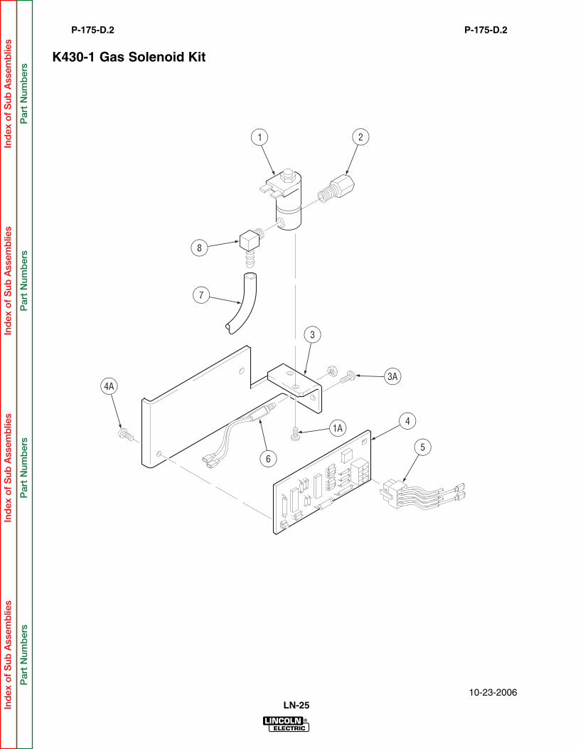
K430-1 Gas Solenoid Kit
Ind
ex o
f S
ub A
ssem
blie
sIn
dex
of
Sub
Ass
emb
lies
Ind
ex o
f S
ub A
ssem
blie
sIn
dex
of
Sub
Ass
emb
lies
Par
t N
umb
ers
Par
t N
umb
ers
Par
t N
umb
ers
Par
t N
umb
ers

ITEM DESCRIPTION PART NO. QTY. 1 2 3 4 5 6 7 8 9 10 11 12
Gas Solenoid & Support Asbly, Includes (1, 1A,3 & 4-7) M17596 1 X1 Solenoid Valve Assembly S18262 1* X1A #8-32 x .31 Sems Screw T10082-27 2 X2 Female Connector T11591-3 1 X3 Valve Support M15316 1 X3A #8 x .375 Self Tapping Screw S8025-4 2 X4 PC Board Assembly M16297-[ ] 1* X4A #8 x .75 Self Tapping Screw S8025-71 2 X5 Plug & Lead Assembly S18250-366 1 X6 Purge Button Assembly T15098 1 X7 Tubing T10642-128 1 X8 Hose Elbow T14914 1 X
Items Not Illustrated
Bulkhead Connector Asbly (Mounts to Case Front) T15153 1 X
Use only the parts marked “x” in the column under theheading number called for in the model index page.
# Indicates a change this printing.
10-23-2006LN-25
# Indicates a change this printing.
P-175.D.3P-175.D.3
Ind
ex o
f S
ub A
ssem
blie
sIn
dex
of
Sub
Ass
emb
lies
Ind
ex o
f S
ub A
ssem
blie
sIn
dex
of
Sub
Ass
emb
lies
Sub
Ass
emb
ly Il
lust
ratio
nS
ub A
ssem
bly
Illu
stra
tion
Sub
Ass
emb
ly Il
lust
ratio
nS
ub A
ssem
bly
Illu
stra
tion

10-23-2006LN-25
P-175-EP-175-E
Reel Stand Assembly
Ind
ex o
f S
ub A
ssem
blie
sIn
dex
of
Sub
Ass
emb
lies
Ind
ex o
f S
ub A
ssem
blie
sIn
dex
of
Sub
Ass
emb
lies
Par
t N
umb
ers
Par
t N
umb
ers
Par
t N
umb
ers
Par
t N
umb
ers

ITEM DESCRIPTION PART NO. QTY. 1 2 3 4 5 6 7 8 9 10 11 12
1 Reel Stand Welded Assembly M15201 1 X X X2 Reel Stand Support Assembly T15102 1 X X X2A #10-24 x .5 Thread Forming Screw S9225-46 1 X X X2B Insulated Fastener T15088 2 X X X3 Spindle Shaft S18138 1 X X X3A 1/2-23 x 1.5 HHCS CF000052 1 X X X3B Lock Washer E106A-15 1 X X X3C Plain Washer S9262-14 1 X X X3D Thumb Screw T14813-A 1 X X X3E Spring T11862-14 1 X X X3F Keyed Washer T12965 1 X X X4 Cable Assembly S18404 1 • X X5 Contactor Assembly & Cable M17586 1* • X X6 Readi-Reel Adapter K363-P 1 X X X7 Spindle M14560 1 X X X7A Retaining Collar M14587-1 1 X X X7B Friction Washer S17435 1 X X X
Use only the parts marked “x” in the column under theheading number called for in the model index page.
# Indicates a change this printing.
10-23-2006LN-25
# Indicates a change this printing.
P-175-E.1P-175-E.1
Ind
ex o
f S
ub A
ssem
blie
sIn
dex
of
Sub
Ass
emb
lies
Ind
ex o
f S
ub A
ssem
blie
sIn
dex
of
Sub
Ass
emb
lies
Sub
Ass
emb
ly Il
lust
ratio
nS
ub A
ssem
bly
Illu
stra
tion
Sub
Ass
emb
ly Il
lust
ratio
nS
ub A
ssem
bly
Illu
stra
tion

DESIRED
DESIREDIN/MININ/MIN
ARCARC
VOLTSUSED
CCCCWIREWIRE
SPEEDSPEED
SETTING
SETTING
(HI(HI of LOWLOW
RANGE)
RANGE)
M-15242
PRESETTING
PRESETTING
CCCCMODEMODE
WIREWIRE
SPEED:
SPEED:
SelectSelect
horisontal
horisontallineline
forfor DESIRED
DESIRED
IN/MIN.IN/MIN.
SelectSelect
diagonal
diagonallineline
forfor ARCARC
VOLTSVOLTS
USED.USED.
Determine
Determinevertic
alvertic
allineline
wherewhere
lineslines
cross.cross.
ThisThisvertic
alvertic
allineline
isisCCCC
WIREWIRE
SPEEDSPEED
SETTING,
SETTING,onon front
frontdial.dial.
SetSet switchswitch
toCC,CC,
andandsetset proper
proper
ARCARC
VOLTSVOLTS
whilewhileweldiweldi
(See(See
exampleexample
forfor 375375IN/MININ/MIN
atat 2929VOLTS.)
VOLTS.)
WIREWIRE
SPEEDSPEED
CALIBRATED
CALIBRATED
INININ/MININ/MIN
WIREWIRE
SPEEDSPEED
CALIBRATED
CALIBRATED
PERPER
GRAPHGRAPH
VARIABLE
VARIABLEWIREWIRE
SPEEDSPEED
FORFOR
CCCC
POWERPOWER
SOURCE
SOURCE
CONSTANT
CONSTANTWIREWIRE
SPEEDSPEED
FORFOR
CVCV
POWERPOWER
SOURCE
SOURCE
WIREWIRE
FEEDFEED
MOREMORE
1.1.
2.2.
3.3.
4.4.
5.5.
700700
650650
600600
550550
500500
450450
400400
350350
300300
250250
200200
150150
100100
50505050
100100150150
200200250250
300300350350
400400450450
500500550550
600600650650
700700
3535
31
2929
2727
2525
2323
21
19
17
15
COLD INCHT13086-99
T13086-99
2B 1
2
2A
3
4
10-23-2006LN-25
P-175-FP-175-F
Box Cover Assembly
Ind
ex o
f S
ub A
ssem
blie
sIn
dex
of
Sub
Ass
emb
lies
Ind
ex o
f S
ub A
ssem
blie
sIn
dex
of
Sub
Ass
emb
lies
Par
t N
umb
ers
Par
t N
umb
ers
Par
t N
umb
ers
Par
t N
umb
ers

ITEM DESCRIPTION PART NO. QTY. 1 2 3 4 5 6 7 8 9 10 11 12
1 Baffle (Includes Speed Nut) S18403 1 • X2 Box Cover M19854 ø 1 X X2A #10-24 x .5 Thread Forming Screw S9225-30 3 X X2B #10-24 Speed Nut T11525-1 1 • X3 CC Mode Decal M15242 1 X X4 Cold Inch Decal T13086-99 1 • X
Use only the parts marked “x” in the column under theheading number called for in the model index page.
# Indicates a change this printing.
10-23-2006LN-25
# Indicates a change this printing.
P-175-F.1P-175-F.1
Ind
ex o
f S
ub A
ssem
blie
sIn
dex
of
Sub
Ass
emb
lies
Ind
ex o
f S
ub A
ssem
blie
sIn
dex
of
Sub
Ass
emb
lies
Sub
Ass
emb
ly Il
lust
ratio
nS
ub A
ssem
bly
Illu
stra
tion
Sub
Ass
emb
ly Il
lust
ratio
nS
ub A
ssem
bly
Illu
stra
tion
ø This part is obsolete and no longer available.

9
2
3
4
5
2A6
7
8
2C
2B
10-23-2006LN-25
P-175-GP-175-G
Case Door Assembly
Ind
ex o
f S
ub A
ssem
blie
sIn
dex
of
Sub
Ass
emb
lies
Ind
ex o
f S
ub A
ssem
blie
sIn
dex
of
Sub
Ass
emb
lies
Par
t N
umb
ers
Par
t N
umb
ers
Par
t N
umb
ers
Par
t N
umb
ers

Use only the parts marked “x” in the column under theheading number called for in the model index page.
# Indicates a change this printing.
ITEM DESCRIPTION PART NO. QTY. 1 2 3 4 5 6 7 8 9 10 11 12
1 Hinge Insulation S20196 1 • • X X1 Hinge Insulation S18110 1 X X • •1A Retaining Clip (Not Shown) M15335 3 X X X X2 Hinge T8755-BT 1 • • X X2 Hinge T8755-BH 1 X X • •2A #6-32 x .375 Pan Head Screw CF000337 4 • • X X2A #6 x .375 Self Tapping Screw S8025-73 5 • X • •2A #6 x .25 Self Tapping Screw S8025-80 4 X • • •2B Lock Washer T9695-2 4 • • X X2C #6-32 HN CF000005 4 • • X X3 Drive Roll Decal S17973 1 X X X X4 Case Door & Hinge Assembly L10926 1 X X X X5 Logo Decal S18241 1 X X X X6 Door Hinge Strip S20197 1 • • X X7 Warning Decal T13470 1 X X X X8 Gun Warning Decal T13297 1 X X X X
10-23-2006LN-25
# Indicates a change this printing.
P-175-G.1P-175-G.1
Ind
ex o
f S
ub A
ssem
blie
sIn
dex
of
Sub
Ass
emb
lies
Ind
ex o
f S
ub A
ssem
blie
sIn
dex
of
Sub
Ass
emb
lies
Sub
Ass
emb
ly Il
lust
ratio
nS
ub A
ssem
bly
Illu
stra
tion
Sub
Ass
emb
ly Il
lust
ratio
nS
ub A
ssem
bly
Illu
stra
tion
ø This part is obsolete and no longer available.

If needed
10-23-2006LN-25
P-175-HP-175-H
Wire Drive Assembly
Ind
ex o
f S
ub A
ssem
blie
sIn
dex
of
Sub
Ass
emb
lies
Ind
ex o
f S
ub A
ssem
blie
sIn
dex
of
Sub
Ass
emb
lies
Par
t N
umb
ers
Par
t N
umb
ers
Par
t N
umb
ers
Par
t N
umb
ers

Use only the parts marked “x” in the column under theheading number called for in the model index page.
# Indicates a change this printing.
ITEM DESCRIPTION PART NO. QTY. 1 2 3 4 5 6 7 8 9 10 1112
Wire Drive Asbly (Above Code 10200) L7333-3 1 • • X X(Includes 1, 10A, 13A-14B, & 16-20A)
Wire Drive Asbly (Below Code 10200) L7333-2 1 • • X X(Includes 1, 10A, 13A-14B, & 16-20A)
Wire Drive Asbly L7333 1 X X • •(Includes 1, 10A, 13A-14B, & 16-20A)
1 Motor & Gearbox Asbly (Above Code 10200) L7332-3 1 • • X X(Includes 2-2C, 9-9B, & 22-24)
1 Motor & Gearbox Asbly (Below Code 10200) L7332-2 1 • • X X(Includes 2-2C, 9-9B, & 22-24)
1 Motor & Gearbox Asbly L7332-1 ø 1 X X • •(Includes items 2-2C, 9-9B, & 22-24)
1A Insulated Fastener T15088 4 X X X X2 Drive Motor Asbly, Includes: 3-8A M15078-4 1* • • X X2 Drive Motor Asbly, Includes: 3-8A M15078-2 1* X X • •2A #10-24 x .5 RHS CF000047 3 X X X X2B Lock Washer E106A-1 3 X X X X2C Plain Washer S9262-27 3 X X X X3 Drive Motor NSS 1* X X X X4 Brush & Spring Asbly M16718-F 2 X X X X5 Brush Cap M14907-G 2 X X X X6 Plain Washer S9262-70 1 X X X X7 Ring Magnet S18011 1 X X X X8 Pinion Gear S17980-2 1 X X X X8A Roll Pin T9967-33 1 X X X X9 Cover & Flange Asbly S18119 1 X X X X9A 1/4-20 x .5 HHCS CF000012 2 X X X X9B Lock Washer E106A-2 2 X X X X10A Self Tapping Screw S8025-19 1 X X X X11 Key (Below Code 10200) M8776-82 1 X X X X12 Collar Asbly (Below Code 10200) T12341 1 X X X X12 Collar Asbly (Above Code 10200) S21193 1 X X X X12A Sems Screw T10082-26 1 X X X X13A Thumb Screw T15046 2 X X X X14 Idle Roll Asbly, Includes: (15 & 15A) S16666-1 1 X X X X14A Speed Clip T10982-7 1 X X X X14B Groove Pin T10580-9 1 X X X X15 Bearing & Shaft Asbly T13244 1 X X X X15A Drive Screw S8025-19 2 X X X X16 Quick Release Asbly M15023-1 1 X X X X16A 1/4-20 x 1.25 HHCS CF000069 1 X X X X16B Pivot Spacer S10918-7 1 X X X X16C Plain Washer S9262-103 1 X X X X17 Locator Bushing T14031 1 X X X X18 Molded Hand Screw T13858 1 X X X X19 Conductor Block M13972-2 1 X X X X19A 1/4-20 x 1.75 HHCS CF000016 2 X X X X19B Lock Washer E106A-2 2 X X X X19C Plain Washer S9262-23 As Req’d X X X X20A 1/2-13 x .75 HHCS CF000020 1 X X X X
10-23-2006LN-25
# Indicates a change this printing.
P-175-H.1P-175-H.1
Ind
ex o
f S
ub A
ssem
blie
sIn
dex
of
Sub
Ass
emb
lies
Ind
ex o
f S
ub A
ssem
blie
sIn
dex
of
Sub
Ass
emb
lies
Sub
Ass
emb
ly Il
lust
ratio
nS
ub A
ssem
bly
Illu
stra
tion
Sub
Ass
emb
ly Il
lust
ratio
nS
ub A
ssem
bly
Illu
stra
tion
NSS - Not Sold Separately
ø This part is obsolete and no longer available.

Use only the parts marked “x” in the column under theheading number called for in the model index page.
# Indicates a change this printing.
ITEM DESCRIPTION PART NO. QTY. 1 2 3 4 5 6 7 8 9 10 1112
21A Sems Screw T10082-4 1 X • X •22 Cover & Flange Asbly S18118 1 X X X X22A 1/4-20 x .5 HHCS CF000012 1 X X X X22B Lock Washer E106A-2 1 X X X X23 Switch Housing Mounting Asbly S21227 1 X X X X23A #10-24 x 1.00 RHS CF000038 1 X X X X23B Lock Washer E106A-1 1 X X X X23C Plain Washer S9262-27 1 X X X X24 Hall Effect Switch Assembly S21419 1* • • X X24 Hall Effect Switch Assembly S18160-1 1* X X • •
10-23-2006LN-25
# Indicates a change this printing.
P-175-H.2P-175-H.2
Ind
ex o
f S
ub A
ssem
blie
sIn
dex
of
Sub
Ass
emb
lies
Ind
ex o
f S
ub A
ssem
blie
sIn
dex
of
Sub
Ass
emb
lies
Sub
Ass
emb
ly Il
lust
ratio
nS
ub A
ssem
bly
Illu
stra
tion
Sub
Ass
emb
ly Il
lust
ratio
nS
ub A
ssem
bly
Illu
stra
tion

LN-25
Use only the parts marked “x” in the column under theheading number called for in the model index page.
# Indicates a change this printing.
P-175-H.3P-175-H.3
10-23-2006
# Indicates a change this printing.
KP653 DRIVE ROLL KITS*
Drive Roll Wire Size INCLUDED WITH KIT
Kit # & Type Spacer Incoming Guide Outgoing Guide Outgoing Guide Insert
KP653-025S .023-.025” Solid T14984 KP2139-1 KP2125-1 KP2124-1
KP653-030S .030” Solid T14984 KP2139-1 KP2125-1 KP2124-1
KP653-035C .035” Cored ------ KP2139-3 KP2125-1 KP2124-1
KP653-035S .035” Solid T14984 KP2139-3 KP2125-1 KP2124-1
KP653-052C .045-.052” Cored ------ KP2139-3 KP2125-1 KP2124-3
KP653-052S .045.-052” Solid T14984 KP2139-3 KP2125-1 KP2124-3
KP653-1/16 1/16” Cored & Solid ------ KP2139-5 KP2125-3 KP2124-5
KP653-3/32C .068-3/32” Cored ------ KP2139-8 KP2125-5 KP2124-8
KP653-7/64H 7/64 Cored ------ KP2139-8 KP2125-4 KP2124-7
KP653-120C .120” Cored ------ KP2139-7 KP2125-4 KP2124-7
KP654 DRIVE ROLL KITS*
Drive Roll Wire Size INCLUDED WITH KIT
Kit # & Type Spacer Incoming Guide Outgoing Guide Outgoing Guide Insert
KP654-035A .035” Aluminum T14984 KP2139-1 KP2125-1 KP2124-1
KP654-3/64A 3/64” Aluminum T14984 KP2139-3 KP1999-1 KP2124-1
KP654-1/16A 1/16” Aluminum T14984 KP2139-5 KP2125-3 KP2124-5
* Drive Rolls Not Sold Separately
Ind
ex o
f S
ub A
ssem
blie
sIn
dex
of
Sub
Ass
emb
lies
Ind
ex o
f S
ub A
ssem
blie
sIn
dex
of
Sub
Ass
emb
lies

3YEAR
WARRANTYPARTS
&LABOR
10-23-2006LN-25
P-175-IP-175-I
Case Front Panel Asbly
Ind
ex o
f S
ub A
ssem
blie
sIn
dex
of
Sub
Ass
emb
lies
Ind
ex o
f S
ub A
ssem
blie
sIn
dex
of
Sub
Ass
emb
lies
Par
t N
umb
ers
Par
t N
umb
ers
Par
t N
umb
ers
Par
t N
umb
ers

ITEM DESCRIPTION PART NO. QTY. 1 2 3 4 5 6 7 8 9 10 11 12
1 Case Front Panel (Black) L7366-1 1 X X X X X X X X X X1A Self Tapping Screw S8025-98 6 • • • • X X X X X X1A Self Tapping Screw S8025-83 6 X X X X • • • • • •
Contactor PC BD Asbly, Includes: (2 & 3-3B) S21415-1 1 • • • • • • • • • XContactor PC BD Asbly, Includes: (2 & 3-3B) S20963 1 • • X • • • X • • •
2 Bracket S18406 2 • • X • • • X • • X2A #8 x .50 Self Tapping Screw S8025-98 4 • • • • • • • • • X2A #8 x .375 Self Tapping Screw S8025-4 4 • • X • • • X • • •3 Contactor PC Board L9670-1 1* • • • • • • • • • X3 Contactor PC Board L9185-2 1* • • X • • • X • • •3A Self Tapping Screw S8025-71 4 • • X • • • X • • X3B Standoff S14020-3 4 • • X • • • X • • X4 Cable Tie T13770-3 1 X X X X X X X X X X5 Cable Tie Mount T13941 1 X X X X X X X X X X6 Toggle Switch T13381-6 1* X X X X X X X X X X7 Potentiometer T10812-92 1* X X X X X X X X X X8 #6 x .25 Drive Screw S8025-8 2 X X X X X X X X X X9 Polarity Switch Shield S19736 1 • X X X X X X X X X10 Toggle Switch T10800-7 1* X X X X X X X X X X11 #10-24 Speed Nut T11525-1 1 X X X X X X X X X X12 Cold Inch Switch Asbly S20957 1 • • X • • • X • • X12 Cold Inch Switch Asbly S19888 ø 1 • • X • • • • • • •
(For Machines with L7535-[ ] Contactor PC Board)13 Front Box Panel M15219 ø 1 X X X X X X X X X X13A #8 x .50 Self Tapping Screw S8025-98 2 • • • • x x x x x x13A #8 x .50 Self Tapping Screw S8025-83 2 x x x x • • • • • •13B Expansion Nut S14020-6 2 X X X X X X X X X X14 Bushing T12380-4 1 X X X X X X X X X X15 Trigger Connector S13100-174 1 • • • • • • • X X X15 Trigger Connector S13100-109 1 X X X X X X X • • •15A #6 x .375 Self Tapping Screw S8025-73 4 X X X X X X X X X X16 Warranty Decal S22127-1 1 X X X X X X X X X X17 Bulkhead Connector Asbly T15153 1 • X X • • X X • X X17A #8 x .375 Self Tapping Screw S8025-4 2 • X X • • X X • X X17A #10-24 x .375 Thread Forming Screw S9225-4 2 X • • X X • • X • •18 Plug Button T10397-4 1 X • • X X • • X • •19 Nameplate - LN25 M15235 1 X X X X X X X X X X19A #10-24 x .375 Thread Forming Screw S9225-61 3 • • • • • • X • • X19A #10-24 x .375 Thread Forming Screw S9225-61 7 • • • • X X • X X •19A #10-24 x .375 Thread Forming Screw S9225-4 3 • • X • • • • • • •19A #10-24 x .375 Thread Forming Screw S9225-4 7 X X • X • • • • • •20 Voltmeter T15134 1 • X X X X X X X X X21 Ground Lead Asbly, Includes: S17211-1 1 X X X X X X X X X X
Ground Clamp M19306 1 X X X X X X X X X X21A Grommet T9274-5 1 X X X X X X X X X X22 Plug Button T10397-19 3 X X X X X X X X X X23 Control Knob S18139-2 1 X X X X X X X X X X24 Front Cover Plate (Code 9157 Only) M15239-1 1 X • • • • • • • • •
Use only the parts marked “x” in the column under theheading number called for in the model index page.
# Indicates a change this printing.
10-23-2006
# Indicates a change this printing.
P-175-I.1P-175-I.1
LN-25Ind
ex o
f S
ub A
ssem
blie
sIn
dex
of
Sub
Ass
emb
lies
Ind
ex o
f S
ub A
ssem
blie
sIn
dex
of
Sub
Ass
emb
lies
Sub
Ass
emb
ly Il
lust
ratio
nS
ub A
ssem
bly
Illu
stra
tion
Sub
Ass
emb
ly Il
lust
ratio
nS
ub A
ssem
bly
Illu
stra
tion
ø This part is obsolete and no longer available.
ITEM DESCRIPTION PART NO. QTY. 1 2 3 4 5 6 7 8 9 10 11 12
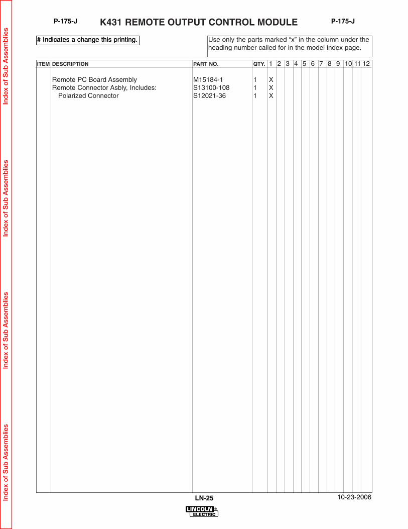
Remote PC Board Assembly M15184-1 1 XRemote Connector Asbly, Includes: S13100-108 1 X
Polarized Connector S12021-36 1 X
K431 REMOTE OUTPUT CONTROL MODULE
Use only the parts marked “x” in the column under theheading number called for in the model index page.
# Indicates a change this printing.
10-23-2006LN-25
# Indicates a change this printing.
P-175-JP-175-J
Ind
ex o
f S
ub A
ssem
blie
sIn
dex
of
Sub
Ass
emb
lies
Ind
ex o
f S
ub A
ssem
blie
sIn
dex
of
Sub
Ass
emb
lies

ITEM DESCRIPTION PART NO. QTY. 1 2 3 4 5 6 7 8 9 10 11 12
Remote PC Board w/Mtg Brackets, Includes: S21414 1 XPC Board M16295-[ ] 1 XSelf Tapping Screw S8025-98 4 X
Remote Connector Asbly, Includes: M17588 1 XPotentiometer T10812-40 1 XConnector (6 Pin) S12021-36 1 XPlug Housing S18249-4 1 XInsulating Washer S10773-75 1 XPotentiometer Insulation S18396 1 X
Self Tapping Screw S8025-73 4 XKnob S18139-2 1 XLead Clamp T12563-7 1 XSelf Tapping Screw S8025-82 1 XPlain Washer S9262-3 1 XPlug & Lead Asbly (Blue) S18250-316 1 XPlug & Lead Asbly (Red) S14165-446 1 XPlug & Lead Asbly (White) S18250-323 1 XJumper Plug T13498-22 1 X
K431-1 REMOTE OUTPUT CONTROL MODULE
Use only the parts marked “x” in the column under theheading number called for in the model index page.
# Indicates a change this printing.
10-23-2006LN-25
# Indicates a change this printing.
P-175-KP-175-K
Ind
ex o
f S
ub A
ssem
blie
sIn
dex
of
Sub
Ass
emb
lies
Ind
ex o
f S
ub A
ssem
blie
sIn
dex
of
Sub
Ass
emb
lies

ITEM DESCRIPTION PART NO. QTY. 1 2 3 4 5 6 7 8 9 10 11 12
Remote Control PC Bd w/Standoffs, Includes: S20967 1 XRemote Control PC Bd Assembly L9244-[ ] 1 XPC Board Mounting Bracket S18406 2 XPlastic Expansion Nut S10420-4 4 XSelf Tapping Screw S8025-14 4 X
Potentiometer & Connector Asbly, Includes: M17251 1 XPotentiometer T10812-40 1 XReceptacle S18249-8 1 XInsulating Washer S10773-75 1 XPotentiometer Insulation S18396 1 X
Receptacle & Lead Asbly S14165-446 1 XPlug & Lead Asbly S18250-316 1 XPlug & Lead Asbly S18250-323 1 XControl Knob S18139-2 1 XSelf Tapping Screw, #8 1/2” long S8025-98 4 XSelf Tapping Screw, #6 3/8” long S8025-73 1 XSelf Tapping Screw, #6 3/4” long S8025-82 1 XLead Clamp T12563-7 1 XPlain Washer S9262-3 1 X
42 VOLT REMOTE CONTROL MODULE
Use only the parts marked “x” in the column under theheading number called for in the model index page.
# Indicates a change this printing.
10-23-2006LN-25
# Indicates a change this printing.
P-175-LP-175-L
Ind
ex o
f S
ub A
ssem
blie
sIn
dex
of
Sub
Ass
emb
lies
Ind
ex o
f S
ub A
ssem
blie
sIn
dex
of
Sub
Ass
emb
lies

ITEM DESCRIPTION PART NO. QTY. 1 2 3 4 5 6 7 8 9 10 11 12
Remote Cable Asbly, Includes: (Specify Length) K432Polarized Socket Connector S12020-28 1 XPolarized Pin Connector S12020-27 1 XConnector to Cable Clamp S12024-1 2 X
Use only the parts marked “x” in the column under theheading number called for in the model index page.
# Indicates a change this printing.
10-23-2006LN-25
# Indicates a change this printing.
P-175-MP-175-M K432 REMOTE CONTROL CABLE
Ind
ex o
f S
ub A
ssem
blie
sIn
dex
of
Sub
Ass
emb
lies
Ind
ex o
f S
ub A
ssem
blie
sIn
dex
of
Sub
Ass
emb
lies

ITEM DESCRIPTION PART NO. QTY. 1 2 3 4 5 6 7 8 9 10 11 12
Remote Cable Extension, Includes: K439Polarized Socket Connector S12023-12 1 XPolarized Pin Connector S12020-27 1 XConnector to Cable Clamp S12024-1 2 X
K439 REMOTE CABLE EXTENSION (50’)
Use only the parts marked “x” in the column under theheading number called for in the model index page.
# Indicates a change this printing.
10-23-2006LN-25
# Indicates a change this printing.
P-175-NP-175-N
Ind
ex o
f S
ub A
ssem
blie
sIn
dex
of
Sub
Ass
emb
lies
Ind
ex o
f S
ub A
ssem
blie
sIn
dex
of
Sub
Ass
emb
lies

LN-25
NOTES
Ind
ex o
f S
ub A
ssem
blie
sIn
dex
of
Sub
Ass
emb
lies
Ind
ex o
f S
ub A
ssem
blie
sIn
dex
of
Sub
Ass
emb
lies

10-23-2006LN-25
P-175-OP-175-O
K433 Power Source Remote Box
Ind
ex o
f S
ub A
ssem
blie
sIn
dex
of
Sub
Ass
emb
lies
Ind
ex o
f S
ub A
ssem
blie
sIn
dex
of
Sub
Ass
emb
lies
Par
t N
umb
ers
Par
t N
umb
ers
Par
t N
umb
ers
Par
t N
umb
ers
ITEM DESCRIPTION PART NO. QTY. 1 2 3 4 5 6 7 8 9 10 11 12
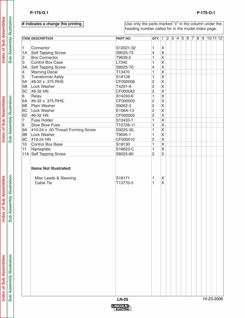
1 Connector S12021-32 1 X1A Self Tapping Screw S8025-73 4 X2 Box Connector T9639-2 1 X3 Control Box Case L7340 1 X3A Self Tapping Screw S8025-70 4 X4 Warning Decal T13470 1 X5 Transformer Asbly S18128 1 X5A #8-32 x .375 RHS CF000006 2 X5B Lock Washer T4291-A 2 X5C #8-32 HN CF000042 2 X6 Relay S14293-6 1 X6A #6-32 x .375 RHS, CF000003 2 X6B Plain Washer S9262-3 2 X6C Lock Washer E106A-13 2 X6D #6-32 HN CF000005 2 X7 Fuse Holder S10433-1 1 X8 Slow Blow Fuse T10728-11 1 X9A #10-24 x .50 Thread Forming Screw S9225-30 1 X9B Lock Washer T9695-1 1 X9C #10-24 HN CF000010 2 X10 Control Box Base S18130 1 X11 Nameplate S16622-C 1 X11A Self Tapping Screw S8025-80 2 X
Items Not Illustrated:
Misc Leads & Sleeving S18171 1 XCable Tie T13770-3 1 X
Use only the parts marked “x” in the column under theheading number called for in the model index page.
# Indicates a change this printing.
10-23-2006LN-25
# Indicates a change this printing.
P-175-O.1P-175-O.1
Ind
ex o
f S
ub A
ssem
blie
sIn
dex
of
Sub
Ass
emb
lies
Ind
ex o
f S
ub A
ssem
blie
sIn
dex
of
Sub
Ass
emb
lies
Sub
Ass
emb
ly Il
lust
ratio
nS
ub A
ssem
bly
Illu
stra
tion
Sub
Ass
emb
ly Il
lust
ratio
nS
ub A
ssem
bly
Illu
stra
tion

LN-25
NOTES
Ind
ex o
f S
ub A
ssem
blie
sIn
dex
of
Sub
Ass
emb
lies
Ind
ex o
f S
ub A
ssem
blie
sIn
dex
of
Sub
Ass
emb
lies


![INDEX [wp02-media.cdn.ihealthspot.com] · 2020. 6. 11. · INDEX 18779CK REDNECK-TRAILER.COM 413 Hydraulic Disc Brake Assemblies..... 149-157 Air Brakes ..... 158](https://static.fdocuments.in/doc/165x107/61265db0416d2854ce4f6ce2/index-wp02-mediacdn-2020-6-11-index-18779ck-redneck-trailercom-413-hydraulic.jpg)