Wing geometry effects on leading-edge vortices - Brenda …brendakulfan.com/docs/lev2.pdf ·...
38
79-1 872 Wing Geometry Effects on Leading Edge Vortices R. M. Kulfan, Boeing Commercial Airplane Co., Seattle, Wash. AlAA AIRCRAFT SYSTEMS AND TECHNOLOGY MEETING August 20-22,1979/ New York, New York 2 For permission l e copy or republish, contact the American Institute of Aeronautics and Aslronavtics.1290 Avenue of the Americas, New York, N.Y. 10019
Transcript of Wing geometry effects on leading-edge vortices - Brenda …brendakulfan.com/docs/lev2.pdf ·...

79-1 872
Wing Geometry Effects on Leading Edge Vortices
R. M. Kulfan, Boeing Commercial Airplane Co., Seattle, Wash.
AlAA AIRCRAFT SYSTEMS AND TECHNOLOGY MEETING August 20-22,1979/ New York, New York
2
For permission l e copy or republish, contact the American Institute of Aeronautics and Aslronavtics.1290 Avenue of the Americas, New York, N.Y. 10019

WING GEOMETRY EFFECTS ON LEADING-EDGE VORTICES
R. M. Kulfan Senior Specialist Engineer
The Boeing Commercial Airplane Company Seattle, Washington.
Abstract
Leading-edge vortices that form at off- design conditions can profoundly influence the aerodynamic characteristics of highly swept slender wings. predict wing geometry effects on the progressive spanwise development of leading-edge vortices is presented. This method, which can account for sweep, camber, twist, airfoil shape, flap deflections, and planform shape, is shown to be a useful tool for aerodynamic design studies. It is shown that suppressing the leading-edge vortex, particularly over the inboard portion of the wing, can cause considerable reduction in drag due to lift. parametric studies are shown.
A straightforward method that can
Results of wing geometry
1.0 Introduction
Familiar characteristics of these wings are illustrated in figure 1. tow drag is achieved at the design condition with attached flow13 2, 3. At off-design conditions, the flow is dramatically changed by the sudden formation of a pair of rather stable leading-edge vortices. is very sharp and thin, the vortices spring from the entire leading edge. If the wing airfoil sections have rounded noses, the vortices first appear near the wing tip and then move progressively inboard with increasing angle of attack. These leading-edge vortices have a profound influence on the wing pressure distribution and, hence, on the aerodynamic performance, stability characteristics, and structural design loads.
If the wing
Numerous ex erimentalq through 14 and theoretical15 tirough 28 studies have provided a fundamental understanding of the nature of these vortices on rather simple thin-wing geometries. In practice, supersonic wing designs, as shown in figure 2, are becoming increasingly more sophisticated through the use of strakes, curved leading edges, wing airfoil shapes that vary across the span, drooped leading edges, and wing camber and twist, as well as variable cruise flap deflections. All of these have an effect on the development and growth of the leading-edge vortices. It is important to understand the effects of wing geometry and flight conditions on the formation and control of these leading-edge vortices in order to develop efficient configurations, as well as to assess their aerodynamic characteristics.
Recently, a straightforward method2g to predict the effects of airfoil shape on the
Cep)ri~hl(i)Amrricin lnsliliilr o i Arrciniliitirr and A m m m # i c \ , In?., 1979. nil r i~ht r r~r r rvrd .
progressive growth of leading-edge vortices was developed. In this paper, that method is extended to account for the effects of winq camber, twist, and flap deflections. The use of the method for conducting parametric design studies is discussed. Additionally, it is shown that, with the exception of ve,y highly swept slender wings, minimum drag due to lift is achieved with attached flow. Low drag due to lift, however, can still be obtained with vortex lift, provided that the leading-edge vortex is restricted to the outer portions of the wing. Hence, aerodynamic designs that restrict the inboard movement of the leading-edge vortex should result in low drag due to lift. Results of using this method to investigate effects of various individual wing geometry parameters on the development of the leading-edge vortex are summarized.
In section 2.0, the basic characteristics of leading-edge vortices on sharp thin slender wings are discussed. The leading-edge suction analogy that forms the basis for the method presented in this paper is discussed in section 3.0. The simple and straightforward technique to predict the effect of pointed nose and round nose airfoils on leading-edge vortex development, and on the associated forces, is summarized in section 4.0. In section 5.0, this method is extended to account for wing warping (e.g., camber, twist, flap deflections) effects. In section 6.0, pressure data obtained on highly swept, flat and twisted wings are used to illustrate the ability of the method to predict the progressive spanwise development of leading- edge vortices on wings with round nose airfoils. The method is also shown to predict the effects of wing twist and leading-edge flap deflections on the vortex development. In section 7.0, the prediction of drag due to lift with vortex flow is discussed. I n section 8.0, the drag due to lift obtained with attached flow is compared to the drag due to lift obtained with vortex flow. It is concluded in this section that, except for very slender wings, the lowest drag due to lift is achieved with attached flow.
By virtue of extensive experimental investigations, the formation of the leading-edge
1

separation vortex is well understood. When a highly swept wing is at an angle of attack, a dividing streamline is formed on the lower surface of the wing. This dividing streamline is similar to the forward stagnation point in two-dimensional flow. The flow inboard of the dividing streamline travels aft, and is swept past the wing trailing edge by the streamwise component of velocity. Lower surface flow forward of the dividing streamline travels from the lower surface around the leading edge to the upper surface.
The expansion of the flow going around the
The steep adverse pressure gradient
leading edge results in a very high negative pressure and a siibsequent steep adverse pressure gradient. can readily cause the three-dimensional boundary layer to separate from the surface. When separation occurs, the lower surface boundary layer leaves the wing along the leading edge and rolls up into a region of concentrated vorticity, which is swept hack over the upper surface of the wing. The strong vorticity, however, draws air ahove the wing into the spiral sheets and, therehy, induces a strong sidewash on the upper surface of the wing that is directed toward the leading edge. This leads to a minimum pressure under the leading-edge vortices on the upper surface of the wing. An increase in lift at a given angle of attack resirlts, and it is this increase that is usually referred to as "nonlinear" or "vortex" lift.
Details of typical leading-edge vortex featores are show in figure 3 . Lower surface flow forward of the dividing streamline separates at the leading edge, S i , and forms the primary vortex. At inoderate angles of attack, an upper surface attachment line, A], is formed. Inboard of the upper surface attachment line, air drawn over the leading-edge vortex attaches to the upper surface, forming a central potential flow region that is swept past the trailing edge. Outboard of A], flow drawn by the influence of the vortex is accelerated strongly toward the leading edge, until it passes heneath this primary vortex. The outward flow then enters a region of increasing pressure sufficient to cause a separation at 52. R s a result, a secondary vortex is formed and Potates opposite to the primary vortex. Flow over the secondary vortex reattaches at A2 and continues on to the leading edge, where it separates again and joins the separated flow from the lower surface, to be swept into the primary vortex. Figure 3 also illustrates the low pressures induced by the primary and the secondary vortices.
This type of flow can exist on highly swept wings at sirpersonic as well as subsonic speeds, provided that the leading edge is swept greater than the angle weak shockwaves make with the freestream direction (i.e., subsonic leading edge).
it l ias been found useful to correlate the data in terms of conditions normal to the leading edge. The incidence angle normal to the leading edge, ( I N , and the nortnal Mach number, MN, are:
a~ = tan-1 (tana/cosA)
In the analyses of leading-edge vortex flow,
M~ = M cos A {I t sinza tan2a
ivhere M = freestream Mach number a = angle of attack A = leading-edge sweep angle
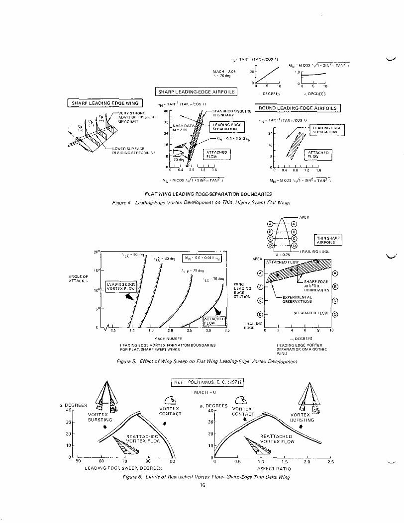
Experimental correlations5 have identified a boundary which indicates the conditions that determine whether attached or separated flow will occur on thin, highly-swept flat wings. This boundary is shown in figure 4. A round leading edge tends to suppress the formation of vortex flow and, thereby, shifts the separation houndary to higher incidence angles, as shown in figure 4.
figure 5 have been constructed using the empirical data of figure 4. This illustrates the Mach number limits where vortex flow can be expected to exist on highly swept wings with different sweep angles. that the thin, sharp flat wing separation boirndary can he applied to wings with varying sweep angles by using the local leading-edge sweep angle.
The type of vortex flow described above is characterized by flow reattachment on the upper surface. All wings will eventually experience various types of flow hreakdown that begin to limit the upper surface reatta~hmentl~. Figure 6 (from reference 15) shows that the range of angle of attack, where reattached vortex flow occurs on highly swept delta wings, is limited for lower sweeps and higher aspect ratios by a phenomenon called "vortex bursting," whereas very highly swept delta wings (low aspect ratio) ultimately experience "vortex contact."
The leading-edge vortex boundaries shown in
This figure also shows
The bursting of a vortex refers to the change of flow pattern from a strong spiral motion about a small rapidly moving core to a weak slow rotational or turbulent m o t i o n about a large stagnant core30. velocities nearly 5 times freestream velocity31 have been measured near the primary vortex cope. At bursting, the vortex core axial flow experiences a sudden deceleration to stagnation, and the core expands greatly about it. extremely slender wings, the vortices from each leading edge can contact and eliminate flow reattachment, thereby reducing vortex lift.
Upstream of bursting, axial
On
The discussions in this paper are limited to conditions (Mach number, angle of attack) that permit vortex flow with reattachment on the upper surface
The detailed characteristics of the flow field associated with the leading-edge vortices are indeed very complicated. Certain simplifying approximations must be made in order to construct mathematical models to be used to predict the effects of the leading-edge vortices.
vortex flow on highly swept wings are the familiar small disturbance potential flow e q ~ a t i o n s ~ ~ . The equations are linear. The solutions to the equations are, however, nonlinear and quite difficult to evaluate. nonlinearity occurs because the solution must provide the strength and location of the
The equations that are used to describe
The
c
L
2
concentrated vortices, as well as the effects on the wing. starting from an initial guess for the strength and location of the vortices.
Iteration techniques are required, L'
Some of the more successful prediction methods that have evolved are discussed in reference 29. These methods have been applied only to thin, highly swept wings where the vortex springs from the entire leading edge. An alternative approach, the suction analogy discussed in section 3 is of particular interest, since this forms the basis for the method presented in this paper.
3.0 Leadinq-Edge Suction Analoqy
i-
d
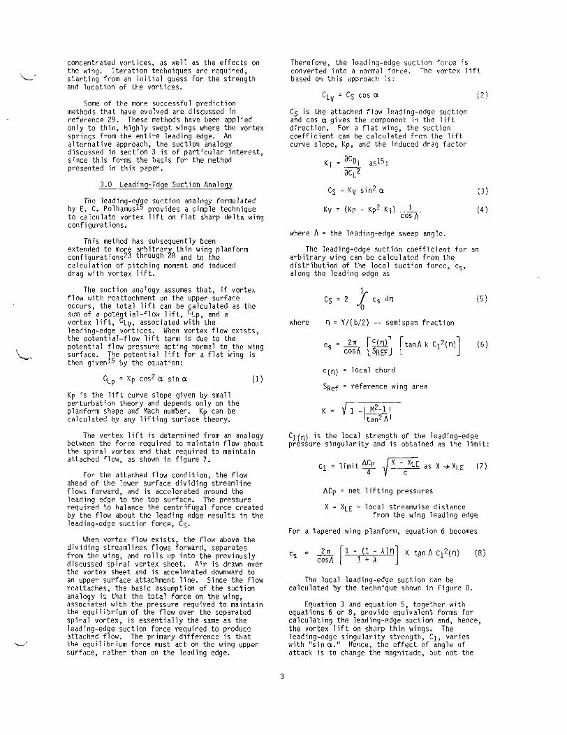
The leading-ed e suction analogy formulated by E. C. Polhamuslg provides a simple technique to calculate vortex lift on flat sharp delta wing configurations.
extended to more arbitrar
calculation of pitching moment and induced drag with vortex lift.
This method has subsequently been thin wing planform configuration^^^ through 3 and to the
The suction analogy assumes that, if vorteh flow with reattachment on the upper surface occurs, the total lift can be calculated as the sum of a potential-flow lift, CLp, and a vortex lift, CLv, associated with the leading-edge vortices. When vortex flow exists, the potential-flow lift term is due to the potential flow pressure acting normal to the wing surface. then givenI5 by the equation:
The potential lift for a flat wing is
C L ~ = ~p cos2 a sin a (1)
Kp is the lift curve slope given by small perturbation theory and depends only on the planform shape and Mach number. calculated by any lifting surface theory.
The vortex lift is determined from an analogy between the force required to maintain flow about the spiral vortex and that required to maintain attached flow, as shown in figure 7.
For the attached flow condition, the flow ahead of the lower surface dividing streamline flows forward, and is accelerated around the leading edge to the top surface. The pressure required to balance the centrifugal force created by the flow about the leading edge results in the leading-edge suction force, Cs.
When vortex flow exists, the flow above the dividing streamlines flows forward, separates from the wing, and rolls up into the previously discussed spiral vortex sheet. Air is drawn over the vortex sheet and is accelerated downward to an upper surface attachment line. Since the flow reattaches, the basic assumption of the suction analogy is that the total force on the wing, associated with the pressure required to maintain the equilibrium of the flow over the separated spiral vortex, is essentially the same as the leading-edge suction force required to produce attached flow. The primary difference is that the equilibrium force must act on the wing upper surface, rather than on the leading edge.
Kp can be
Therefore, the leading-edge suction force is converted into a normal force. The vortex lift based on this approach is:
Cs is the attached flow leading-edge suction and cos u gives the component in the lift direction. For a flat wing, the suction coefficient can be calculated from the lift curve slope, Kp, and the induced drag factor
( 3 )
where A = the leading-edge sweep angle.
The leading-edge suction coefficient for an arbitrary wing can be calculated from the distribution of the local suction force, cs. along the leading edge as
where rl = Yl(bl2) -- semispan fraction
c(q) = local chord
SRef = reference wing area
Cl(,,) is the local strength o f the leading-edge pressure singularity and is obtained as the limit:
ACp = net lifting pressures
X - X L E = local streamwise distance from the wing leading edge
For a tapered wing planform, equation 6 becomes
The local leading-edge suction can be calculated by the technique shown in figure 8.
equations 6 or 8, provide equivalent forms for calculating the leading-edge suction and, hence, the vortex lift on sharp thin wings. The leading-edge singularity strength, C1. varies with "sin a," Hence, the effect of angle of attack is to change the magnitude, but not the
Equation 3 and equation 5, together with
3

shape, of the vortex lift distribution in the streamwise direction.
The drag due to lift for thin sharp-edge flat wings is calculated from the potential and vortex lift as
a = angle of attack
The pitching moment is calculated assuming that the streamwise distribution of potential lift is not affected by the vortex flow, and that the vortex lift acts normal to the wing near the leading edge.
The suction analoov has been shown to orovide _ _ accurate estimates of lift, induced drag, and pitching moment for a aide range of sharp-edge flat wing configurations23 through 2 8 , should be noted that the suction analogy does not, however, provide wing curface pressure distributions.
It
accurate estimatpc of'iift. induced draa. and _., ~~~ ~ ~~
pitching moment for a aide range of sharp-edge flat wing configurations23 through 2 8 , should be noted that the suction analogy does not, however, provide wing surface pressure
It
distributions.
4.0 Prediction of Airfoil Shake Effects
Experimental studies have shown that wing thickness has a retarding effect on the growth of leading-edge vortices. The experimental results indicate that, because of thickness, the vortex f o r m s at an angle of attack greater than zero deg. The vortex then grows with reduced strength relative to a very thin wing at the same angle of attack. The retarding effect depends not only on the thickness distribution, but also on whether the airfoil nose is pointed or round.
4.1 Pointed Nose Airfoils
Experimental resultsl3 that were obtained on a simple delta wing with various symmetric and asymmetric wedge shape thickness distributions indicate that vortex flow is largely independent of the shape of the lower surface.
Conversely, these results imply that the vortex formation, on a wing with a sharp-edge airfoil, is dependent only on the shape of the upper surface. With this key assumption, the effects of pointed nose airfoil thickness can be estimated by the following simple technique29:
1. The flow is assumed to remain attached until the upper surface of the wing is at an angle of attack. F o r a wing with a constant thickness/chord ratio section, this occiirs at an angle of attack, a , equal to the upper surface slope, 6 ~ .
O f attack greater than 6 ~ , as though the vortex were starting to grow on a thin wing at an effective angle of attack, aE, equal to the actual angle
2. The vortex is assumed to grow at angles
Of attack 'ninus the upper surface nose angle.
The nose angle used in equation 10 for a symmetric wedge configuration is equal to half the included angle. An area- averaged nose angle is used for curved pointed airfoils.
3. The vortex lift for a flat constant Section wing is t h w calculated as:
C L " = K V cosa E sin? aE (11)
4. The total lift i s the sum of the potential lift (equation 1) and the vortex lift (equation 11).
Pitching moment is obtained as the sum of the potential flow pitching moment plus pitching moment associated with the reduced vortex strength. The calculation of drag due to lift is discussed in secton 7.0.
Figure 9 contains a comparison of predicted lift and pitching moment, using this approach, with test data. Additional test versus theory comparisons, shown in reference 29, appear to substantiate this simple approach.
Y
a~('?) = a - 6~('1)
rl = semispan station
In this case, the vortex does not spring uniformly from the leading edge, but moves progressively inboard as the angle o f attack exceeds the local upper surface slope.
4.2 Round Nose Airfoils
Round nose airfoils on highly swept wings reduce the adverse pressure near the leading edge of highly swept wings. greatest over the inboard portion of the wing. Leading-edge separation in this case starts near the wing tip and moves progressively inboard with increasing angle of attack.
to account for the retarding effect of the round nose airfoil is summarized in figure 10, and includes the following steps:
This effect is
The straightforward method that was devised
a. Sections of the wing perpendicular to the leading edge are approximated locally by parabolas. The local parabolic nose drag, CR. is then calculated following the technique described in references 32, 33 and 34, The parabolic nose drag for a tapered wing is:
4

L . 1
h.
C.
where R l / c i s the ratio of the local perpendicular nose radius to the local streamwise chord.
The local parabolic nose drag is then compared with the local leading-edge suction coefficient given by equation 8.
As previously mentioned, the local leading-edge singularity strength, C1, varies with "sina"
i. r l
The vortex is assumed to begin to grow locally when the suction force, cs, exceeds the parabolic nose drag, CR. Combining equations 13, 14, and 8 , this local separation angle, a,, can be expressed a s :
where CIREF is the local leading singularity strength calculated by linear theory at the reference angle of attack, QREF.
The vortex is assumed to grow locally when the angle of attack exceeds the local separation angle, as. The local vortex strength for a tapered wing is given by the effective suction coefficient, CSEFF, as: (161
Ciy = local sectional vortex lift. "Sign(C1)" accounts for positive or negative lift depending if the vortex falls on the upper or lower surface of the winq.
moments using this method with test data for a 60-deg delta wing with a rounded nose airfoil section. The results indicated that the theoretical method for calculating the effects of round nose airfoil on vortex lift does properly predict the progressive development of the leading-edge vortex, as well as the vortex lift and pitching moment on highly swept flat wings. Furthermore, this method also indicates areas on a high1 swept wing where attached flow theory applier39.
5.0 Extension to Warped Winqs
The local strength of the leading-edge pressure singularity, C1, which is used to determine the leading-edge suction, cs, is calculated from a linear theory pressure distribution. The nonlinearity in the suction analogy occurs because the leading-edge suction depends on ''C]z" and also because exact "sina" and "cos a" relations are used. An additional nonlinearity was introduced by the methods in the previous section in accounting for the retarding effects of pointed nose and round nose airfoils on the progressive development of the leading- edge vortex.
calculation, C1, is linear, the methods for predicting the round nose or pointed nose airfoils effects on vortex development can readily be extended to arbitrary highly swept warped wings that are cambered, twisted, or have deflected leading-edge or trailing-edge devices.
The lifting pressure distribution on an arbitrary cambered and twisted wing at angle of attack and with flap deflections can be calculated as the linear sum of the following elements :
Since the essential element in this
A flat wing at angle of attack
The cambered and twisted wing at zero angle of attack
A flat wing with flap deflections at zero angle of attack
Typical spanwise variations of the parabolic Similarly, the leading-edge pressure nose drag and the leading-edge suction are shown in figure 10 for a delta wing to illustrate this calculation concept. The vortex is predicted to exist on areas of the wing where the suction
remainder of the wing, the flow is attached.
singularity can be calcuated as the scaleable sum of the aforementioned' elements as:
force exceeds the parabolic nose drag. On the + CIT('I) [TFAC]+ (18)
The total lift is calculated as the sum of the potential flow lift plus the vortex lift obtained by integration of the local vortex lift along the wing leading edge. The pitching moment is calculated in a similar manner, again assuming where II = semispan station that the streamwise potential flow lift distribution is unchanged by the vortex. C~F(Q) = the local leading-edge
singularity strength for the flat wing at the reference angle of attack, QREF
Figure 11 is a sample comparison from reference 29 of predicted lift and pitching -
5

the local leading-edge singularity strength for the cambered and twisted wing at zero angle of attack
'IT(?) =
c16i(n) = the local leading edge pressure singularity strength for the flat wing at zero anqle of attack with "i th" surface deflected on angle ANi
"sin a!' scales the flat wing contribution to other angles of attack. Similarly, "TFAC" and "sin 6Ni" are used to scale the camberltwist, and flap deflection contributions, respectively.
For simplicity, let the sum of the warped surface contributions to the leading-edge singularity strength be denoted "AC1".
For warped wings with round nose airfoils, the leading-edge vortex is still assumed to occur when the local leading-edge suction, cs, equals the local nose pressure force, CR.
Combining equations 8 and 13, the vortex develops locally when
cl(n) = .& k tan h
Combining equations 18, 19, and 20,we obtain two possible vortex separation angles:
where as,(^) = the angle of attack at which the vortex appears on the "mer surface of the wing
the angle of attack at which the vortex appears on the lower surface of the wing.
asL(n) =
The angle of attack range for which the round airfoil locally retards the growth of the leading-edge vortex is . asL(ri)".
angle Of attack range for which the leading-edge vortex is retarded by an amount of 'hq". shift is obtained by setting the leading-edge radius to zero in either equation 21 or 22
The effect of wing warp is to shift the local
This
The local leading-edge suction f o r selected values of TFAC and 6Ni (i.e., fixed warped wing shape) is then calculated using equation 6 with an effective angle of attack, aEFF(?) , g' iven as:
e no vortex ----- aEFF('I) = 0 IFaSLLaLaSU
e vortex on upper surface -----
e vortex on lower surface ----- aEFF(?) = a - Q S " ( n ) I F a > asU
a E F F ( ' I ) = a - a S L ( n ) I F a < a S , ( n )
The local vortex lift, "CQv", is then :alculated from equation 17.
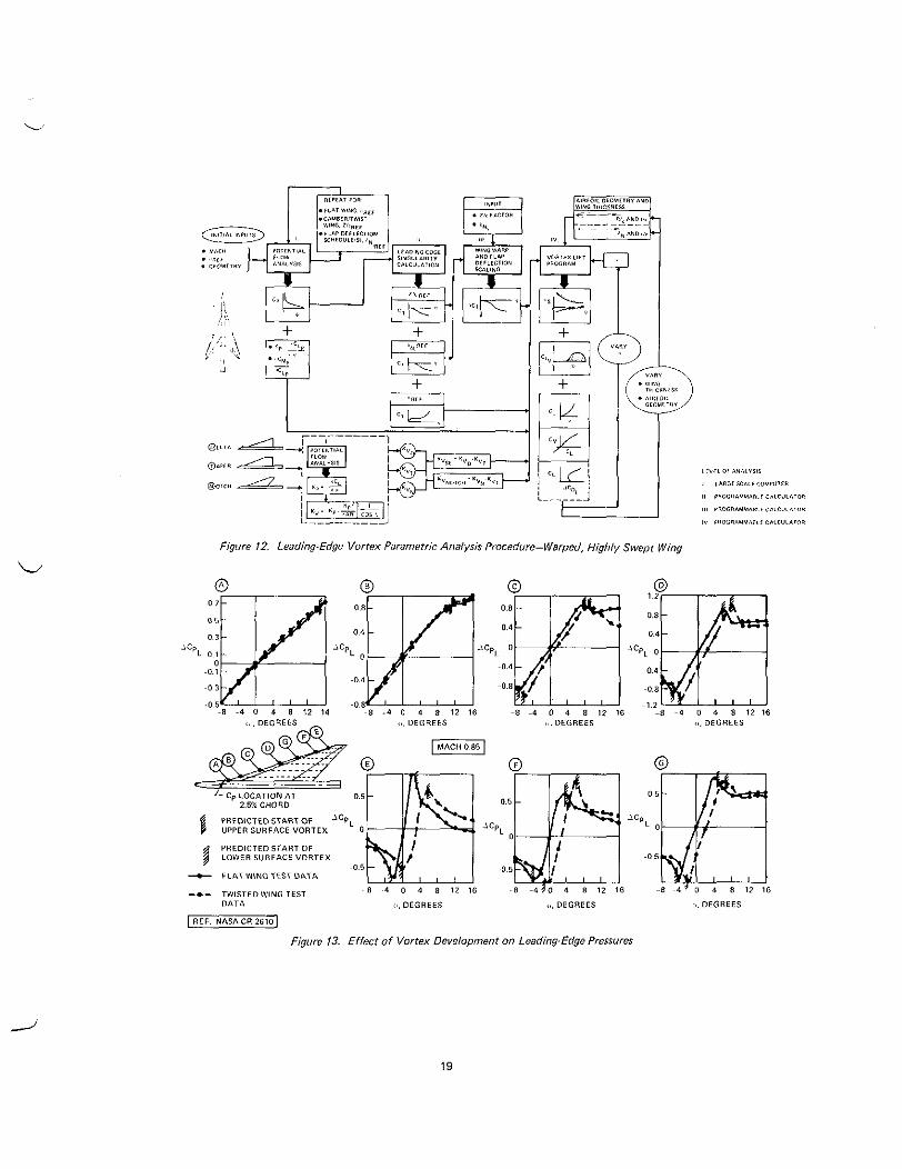
This previously described calculation procedure can be easily used to conduct rapid parametric analyses on warped highly swept wings with round nose airfoils. The technique is shownin figure 12.
First, potential flow analyses are made for the specified configuration at the desired Mach number. Calculations include:
e Flat wing analyses at aREF Cambered and twisted wing analyses at Zero deg angle of attack
e Flat wing with the flaps deflected, 6Ni
The calculated results include the potential flow lift curve slope ( K p ) , the potential flow aerodynamic center (acMp/aCL ), and the lifting pressure distributiois for each of the above configurations.
The leading-edge singularity strength, C1, distribution is computed for each of the aforementioned lifting pressure distributions.
For selected flap deflections and camber/twist scaling factors, the total warped wing singularity strength is calculated from equation 19.
The leading-edge singularity distributions, potential flow lift curve slope,and aerodynamic center are then used to calculate the vortex formation angle along the wing using equations 20 and 21. The vortex lift, distribution, total lift,and pitching moment are then calculated.
The final three steps can be calculated on
as,)
a programmable calculator. Thus, parametric analyses can easily he made to provide an understanding of wing geometry effects on leading-edge vortices.
Detailed analyses of pressure and force data, obtained on two NASA arrow-wing models, were then made to evaluate this procedure for predicting the progressive development of leading-edge vortices on warped wings with round nose airfoils. Results of these investigations are described in the next section.
6.0 NASA Arrow-Wino Models
A wind tunnel test of an arrow-wing body configuration consisting of flat and twisted
6
wings, as well as a variety of leading- and L' trailing-edge control surface deflections, was
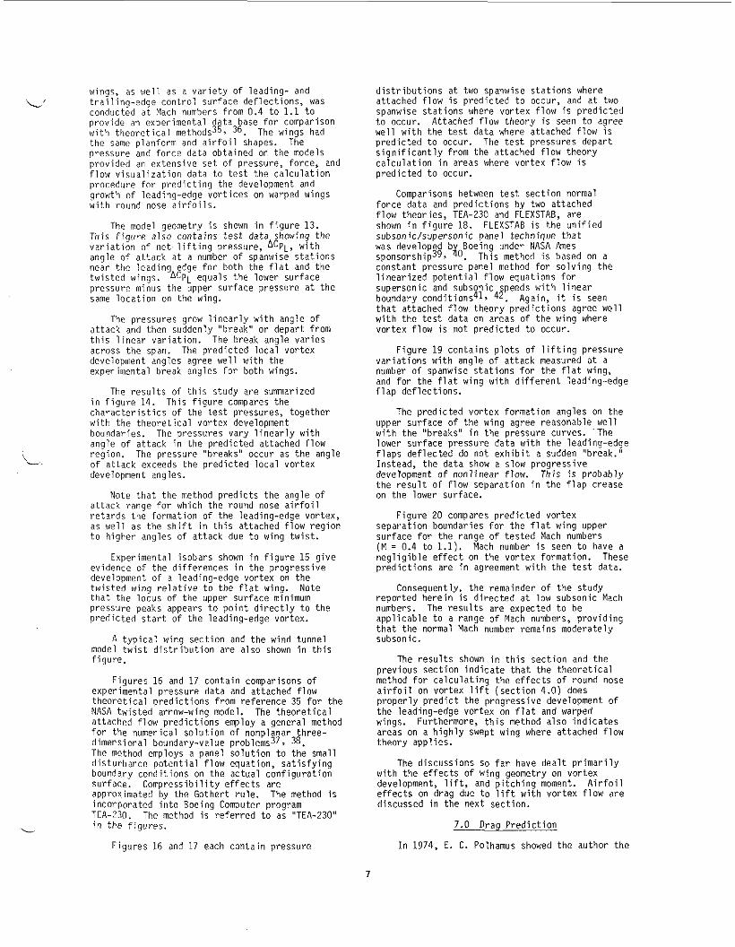
conducted at Mach numbers from 0.4 to 1.1 to provide an experimental data base for comparison with theoretical methods35, 36. The wings had the same planform and airfoil shapes. The pressure and force data obtained on the models provided an extensive set of pressure, force, and flow visualization data to test the calculation procedure for predicting the development and growth of leading-edge vortices on warped wings with round nose airfoils.
The model genmetry is shown in figure 13. This figure also contains test data showing the variation of net lifting pressure, fJCPt, with angle of attack at a number of spanwise stations near the leading edge for both the flat and the twisted wings. ACPt equals the lower surface pressure minus the upper surface pressure at the same location on the wing.
The pressures grow linearly with angle of attack and then suddenly "break" or depart from this linear variation. The break angle varies across the span. The predicted local vortex development angles agree well with the experimental break angles for both wings.
The results of this study are summarized in figure 14. This figure compares the characteristics of the test pressures, together with the theoretical vortex development boundaries. angle of attack in the predicted attached flow region. of attack exceeds the predicted local vortex development angles.
Note that the method predicts the angle of attack range for which the round nose airfoil retards the formation of the leading-edge vortex, as well as the shift in this attached flow region to higher angles of attack due to wing twist.
The pressures vary linearly with
The pressure "breaks" occur as the angle i. ~
Experimental isobars shown in figure 15 give evidence of the differences in the progressive development of a leading-edge vortex on the twisted wing relative to the flat wing. that the locus of the upper surface minimum pressure peaks appears to point directly to the predicted start of the leading-edge vortex.
model twist distribution are also shown in this figure.
Figures 16 and 17 contain comparisons of experimental pressure data and attached flow theoretical predictions from reference 35 for the NASA twisted arrow-wing model. attached flow predictions employ a general method for the numerical solution of nonplanar three- dimensional boundary-value problems373 38. The method employs a panel solution to the small disturbance potential flow equation, satisfying boundary conditions on the actual configuration surface. Compress i bi 1 i ty effects are approximated by the Gothert rule. The method is incorporated into Roeing Computer program TEA-230. The method is referred to as "TEA-230'' in the figures.
Note
A typical wing section and the wind tunnel
The theoretical
Figures 16 and 17 each contain pressure
distributions at two spanwise stations where attached flow is predicted to occur, and at two spanwise stations where vortex flow is predicted to occur. Attached flow theory is seen to agree well with the test data where attached flow is predicted to occur. The test pressures depart significantly from the attached flow theory calculation in areas where vortex flow is predicted to occur.
force data and predictions by two attached flow theories, TEA-230 and FLEXSTAB, are shown in figure 18. subsonic/supersonic panel technique that was developed b Boeing under NASA Ames ~ponsorship~~, $0. This method is based on a constant pressure panel method for solving the linearized potential flow equations for supersonic and subsonic speeds with linear boundary conditions41, 42. Again, it is seen that attached flow theory predictions agree well with the test data on areas of the wing where vortex flow is not predicted to occur.
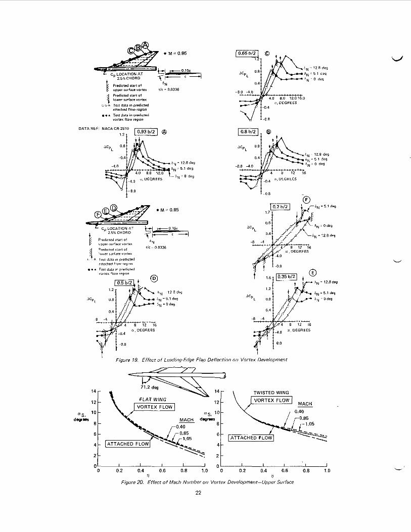
variations with angle of attack measured at a number of spanwise stations for the flat wing, and for the flat wing with different leading-edge f 1 ap deflections.
upper surface of the wing agree reasonable, well with the "breaks" in the pressure curves. The lower surface pressure data with the leading-edge flaps deflected do n o t exhibit a sudden "break." Instead, the data show a slow progressive development of nonlinear flow. This i s probably the result of flow separation in the flap crease on the lower surface.
Figure 20 compares predicted vortex separation boundaries for the flat wing upper surface for the range of tested Mach numbers ( M = 0.4 to 1.1). Mach number is seen to have a negligible effect on the vortex formation. predictions are in agreement with the test data.
reported herein is directed at low subsonic Mach numbers. The results are expected to be applicable to a range of Mach numbers, providing that the normal Mach number remains moderately subsonic.
The results shown in this section and the previous section indicate that the theoretical method for calculating the effects of round nose airfoil on vortex lift (section 4.0) does properly predict the progressive development of the leading-edge vortex on flat and warped wings. Furthermore, this method also indicates areas on a highly swept wing where attached flow theory applies.
Comparisons between test section normal
FLEXSTAB is the unified
Figure 19 contains plots of lifting pressure
The predicted vortex formation angles on the
These
Cnnsequently, the remainder of the study
The discussions so far have dealt primarily with the effects of wing geometry on vortex development, lift, and pitching moment. Airfoil effects on drag due to lift with vortex flow are discussed in the next section.
7.0 Draq Prediction
I n 1974, E. C. Polhamus showed the author the
7
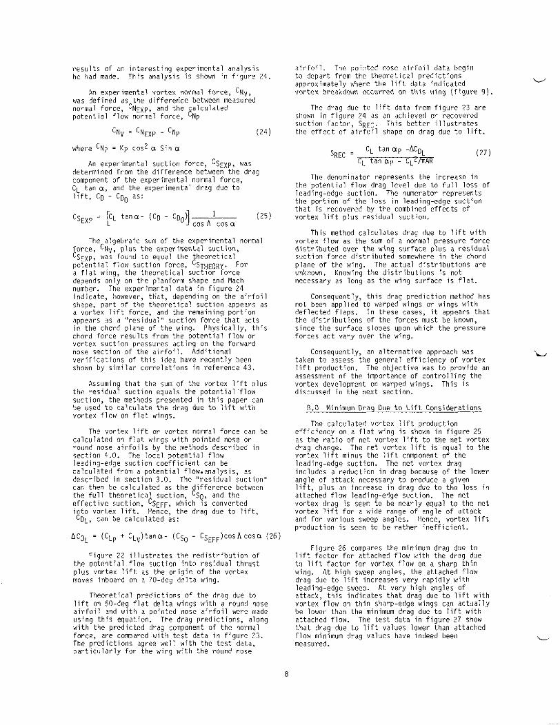
r e s u l t s of an i n t e r e s t i n g exper imenta l a n a l y s i s he had made, Th is a n a l y s i s i s shown i n f i g u r e 24.
An exper imenta l v o r t e x normal force, cN", vas de f ined as the d i f f e r e 6 c e between measured normal f o rce , c N ~ x p , and the c a l c u l a t e d p o t e n t i a l f l o w normal fo rce , C N ~
cN" = C N ~ y , p - cNp (24)
where cNp = Kp cos2 0 Sin Q
CL t an Q , and t l i f t , Cg - C Q ~ as:
The a l g e b r a i c sum o f t he exper imenta l normal fo rce , cN\i, p l u s t h e exper imenta l s u c t i o n , % E X ? , was found t o equal t he t h e o r e t i c a l p o t e n t i a l f l o w s u c t i o n fo rce , C S ~ u ~ o ~ y . a f l a t wing, t he t h e o r e t i c a l s u c t i o n f o r c e depends o n l y on t he p lan form shape and Mach number. The exper imenta l d a t a i n f i g u r e 24 i n d i c a t e , however, t t i a t , depending on the a i r f o i l shape, p a r t o f t he t h e o r e t i c a l s u c t i o n appears as a v o r t e x l i f t force, and the remain ing p o r t i o n appears as a " r e s i d u a l " s u c t i o n f o r c e t h a t ac ts i n the chord plane o f t he wing. P h y s i c a l l y , t h i s chord f o r c e r e s u l t s f rom the p o t e n t i a l f l o w or v o r t e x s u c t i o n pressures a c t i n g on the forward nose s e c t i o n o f t he a i r f o i l . A d d i t i o n a l v e r i f i c a t i o n s of t h i s idea have r e c e n t l y been shown by s i m i l a r c o r r e l a t i o n s i n r e f e r e n c e 43.
For
Assuming t h a t t he sum o f t he v o r t e x l i f t p lus the r e s i d u a l s u c t i o n equals the p o t e n t i a l f l o w suc t ion , t he methods presented i n t h i s paper can be used t o c a l c u l a t e t h e drag due t o l ift with v o r t e x f l o w on f l a t wings.
c a l c u l a t e d on f l a t wings w i t h p o i n t e d nose or round nose a i r f o i l s by the niethods descr ibed i n s e c t i o n 4.0. The l o c a l p o t e n t i a l f l o w leading-edge s u c t i o n c o e f f i c i e n t can be c a l c u l a t e d from a p o t e n t i a l f low.analysis, as descr ibed i n s e c t i o n 3.0. The " r e s i d u a l s u c t i o n " can then he c a l c u l a t e d as the d i f f e r e n c e between the f u l l t h e o r e t i c a l suc t ion , cSo, and the e f f e c t i v e s u c t i o n , %EFF, which i s conver ted i n t o v o r t e x l i f t . Hence, the draa due t o l i f t .
The v o r t e x l i f t o r v o r t e x normal f o r c e can be
c o ~ , can be c a l c u l a t e d a s :
ACDL = (CL? + C ~ ~ l t a n a - (Cs0 - CsEFF)cosAcosa (261
F i g u r e 22 i l l u s t r a t e s the r e d i s t r i b u t i o n of t he p o t e n t i a l f l o w s u c t i o n i n t o r e s i d u a l t h r i i s t p l u s v o r t e x l i f t as t he o r i g i n o f the v o r t e x moves inboard on a 70-deg d e l t a wing.
l i f t on 60-deg f l a t d e l t a wings w i t h a round nose a i r f o i l and w i t h a p o i n t e d nose a i r f o i l were made u s i n g t h i s equat ion. The drag p r e d i c t i o n s , a long w i t h the p r e d i c t e d drag component o f t he normal f o rce , are compared w i t h t e s t data i n f i g u r e 23. The p r e d i c t i o n s agree w e l l w i t h the t e s t data, p a r t i c u l a r l y f o r t he wing w i t h the round nose
T h e o r e t i c a l p r e d i c t i o n s of t he drag due t o
a i r f o i l . The p o i n t e d nose a i r f o i l da ta begin t o depart f rom the t h e o r e t i c a l p r e d i c t i o n s approxi inately where the l i f t data i n d i c a t e d v o r t e x breakdown occur red on t h i s wing ( f i g u r e 9 ) .
shown i n f i g u r e 24 as an achieved or recovered s u c t i o n f a c t o r , SREC. Th is b e t t e r i l l u s t r a t e s the e f f e c t o f a i r f o i l shape on drag due t o l i f t .
v
The drag due t o l i f t data f rom f i g u r e 1 3 are
( 2 7 1 C L t a n a p -ACgL
CL tan ap --vi%? SREC =
Th is method c a l c u l a t e s drag due t o l i f t w i t h v o r t e x f l o w as the sum of a normal p ressure fo rce d i s t r i b u t e d over t h e wing s u r f a c e p l u s a r e s i d u a l s u c t i o n f o r c e d i s t r i b u t e d somewhere i n the chord p lane o f t he wing. The ac tua l d i s t r i b u t i o n s are unknown. Knowing the d i s t r i b u t i o n s i s no t necessary as l ong as the wing surface i s f l a t .
Consequently, t h i s drag p r e d i c t i o n method has no t been a p p l i e d t o warped wings or wings w i t h d e f l e c t e d f l a p s . In these cases, i t appears t h a t t he d i s t r i b u t i o n s of t he f o r c e s must he known, s i n c e the s u r f a c e s lopes upon which the pressure fo rces a c t vary over the wing.
taken t o assess the general e f f i c i e n c y o f v o r t e x l i f t produc t ion . The o h j e c t i v e was t o p r o v i d e an assessment o f t he importance o f c o n t r o l l i n g the v o r t e x development on warped wings. Th is i s discussed i n the nex t sec t ion .
Consequently, an a l t e r n a t i v e approach was L
8.0 Minimum D r a t Due t o L i f t Consider-
The c a l c u l a t e d v o r t e x l i f t p r o d u c t i o n e f f i c i e n c y on a f l a t wing i s shown i n f i g u r e 25 as the r a t i o o f ne t v o r t e x l i f t t o the n e t v o r t e x drag change. The ne t v o r t e x l i f t i s equal t o the v o r t e x l i f t minus the l i f t component o f the leading-edge suc t ion . i n c l u d e s a r e d u c t i o n i n drag because o f t he lower angle o f a t t a c k necessary t o produce a g iven l ift, p l u s an inc rease i n drag due t o the loss i n a t tached f l o w leading-edge suc t ion . The ne t v o r t e x drag i s seen t o be n e a r l y equal t o the ne t v o r t e x l i f t f o r a wide range of angle o f a t t a c k and f o r var ious sweep angles. Hence, v o r t e x l i f t p r o d u c t i o n i s seen t o be r a t h e r i n e f f i c i e n t .
The ne t v o r t e x drag
F i g u r e 26 compares the minimum drag due t o l i f t f a c t o r f o r a t tached f l o w w i t h the drag due t o l i f t f a c t o r for v o r t e x f low on a sharp t h i n wing. A t h igh sweep angles, t he a t tached f low drag due t o l i f t increases very r a p i d l y w i t h leading-edge sweep. a t t a c k , t h i s i n d i c a t e s t h a t drag due t o l i f t w i t h v o r t e x f l o w on t h i n sharp-edge wings can a c t u a l l y he lower than the minimum drag due t o l i f t w i t h a t tached f l ow . The t e s t da ta i n f i g u r e 2 7 show t h a t drag due t o l i f t values lower than a t tached f l o w minimum drag values have indeed been measured.
A t very h i g h angles of
8
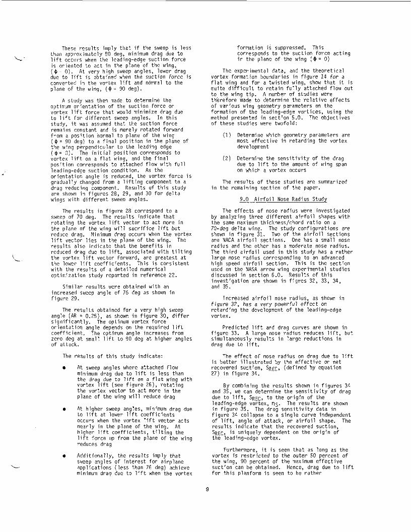
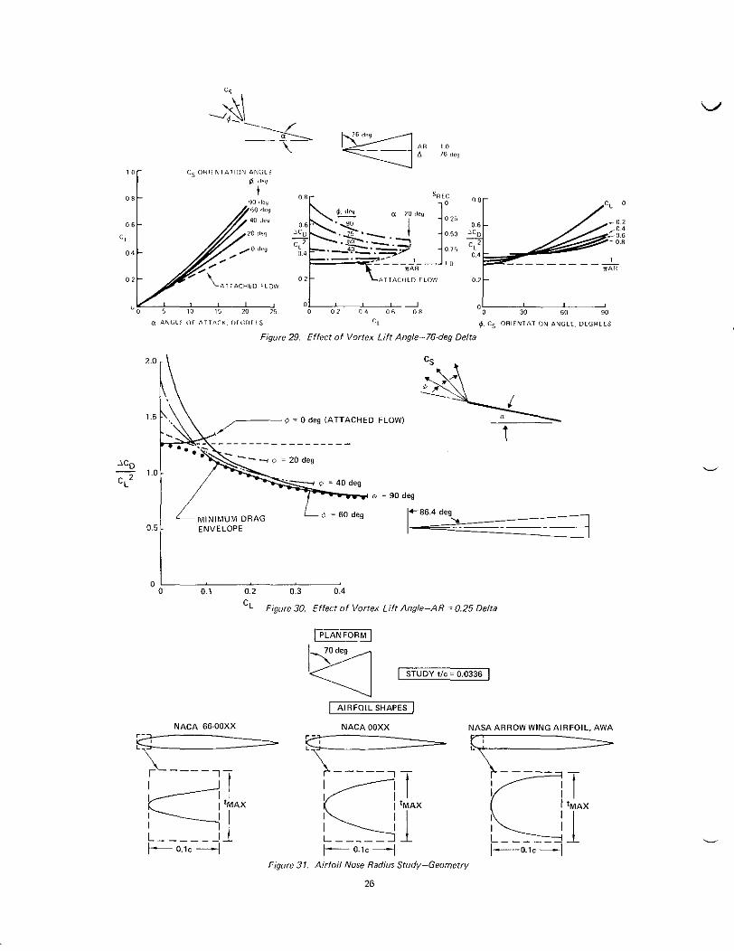
These results imply that if the sweep is less than approximately EO deg, minimum drag due to lift occiirs when the leading-edge suction force is oriented to act in the plane of the wing, ( 6 = 0). At very high sweep angles, lower drag due to lift is obtained when the suction force is converted in the vortex lift and normal to the plane of the wing, ( 4 = 90 deg).
optimum orientation of the suction force or vortex lift force that would minimize drag due to lift for different sweep angles. In this study, it was assumed that the suction force remains constant and is merely rotated forward from a position normal to plane of the wing ( 4 = 90 deg) to a final position in the plane of the wing perpendicular to the leading edge ( + = 0). vortex lift on a flat wing, and the final position corresponds to attached flow with full leading-edge suction condition. As the orientation angle is reduced, the vortex force is gradually changed from a lifting component to a drag reducing component. Results of this study are shown in figures 28, 29, and 30 for delta wings with different sweep angles.
A study was then made to determine the
The initial position corresponds to
formation is suppressed. This corresponds to the suction force acting in the plane of the wing ( 6 - 0)
The experimental data, and the theoretical vortex formation boundaries in figure 14 for a flat wing and for a twisted wing, show that it is quite difficult to retain fully attached flow out to the wing tip. A number of studies were therefore made to determine the relative effects of various wing geometry parameters on the formation of the leading-edge vortices, using the method presented in section 5.0. The objectives of these studies were twofold:
Determine which geometry parameters are most effective in retarding the vortex development
Determine the sensitivity of the drag due to lift to the amount of wing span on which a vortex occurs
(1)
(2)
The results of these studies are summarized in the remaining section of the paper.
9.0 Airfoil Nose Radius Study
i
L
results also indicate that the benefits in reduced drag due to lift, associated with tilting the vortex lift vector forward, are greatest at the lower lift coefficients. This is consistent with the results of a detailed numerical optimization study reported in reference 22.
Similar results were obtained with an increased sweep angle of 76 deg as shown in figure 29.
The rezults obtained for a very high sweep angle (AR 2 0.25), as shown in figure 30, differ significantly. The optimum vortex force orientation angle depends on the required lift coefficient. The optimum angle increases from zero deg at small lift to 90 deg at higher angles of attack.
The re?,ults of this study indicate:
a At sweep angles where attached flow minimum draq due to lift is less than the drag du; to lift on 4 flat wing with vortex lift (see figure 26). rotating the vortex vector to act more i n the plane of the wing will reduce drag
a At higher sweep angles, minimum drag due to lift at lower lift coefficients occurs when the vortex lift vector acts nearly in the plane of the wing. higher lift coefficients, tilting the lift force up from the plane of the wing reduces drag
At
a Additinnallv. the results imlv t h a t sweep angle5'of interest for' airplane applications (less than 76 deg) achieve minimum draq due to lift when the vortex
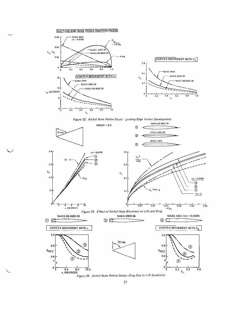
large nose radius corresponding to an advanced high speed airfoil section. This is the section used on the NASA arrow wing experimental studies discussed in section 6.0. Results of this investigation are shown in figres 32, 33, 34, and 35
Increased airfoil nose radius, as shown in figure 32, has a very powerful effect on retarding the development of the leading-edge vortex.
Predicted lift and drag curves are shown in figure 33. A large nose radius reduces lift, but simultaneously results in large reductions in drag due to lift.
The effect of nose radius on drag due to lift is better illustrated by the effective or net recovered suction, SREC, (defined by equation 27) in figure 34.
By combining the results shown in figures 34 and 35, we can determine the sensitivity of drag due to lift, SREC, to the origin of the leading-edge vortex, 'IS. in figure 35. figure 34 collapse to a single curve independent of lift, angle of attack, or airfoil shape. The results indicate that the recovered suction, SREC, is uniquely dependent on the origin of the leading-edge vortex.
Furthermore, it is seen that as long as the vortex is restricted to the outer 50 percent of the wing, 90 percent of the maximum effective suction can be obtained. Hence, drag due to lift for this planform is seen to be rather
The results are shown The drag sensitivity data in
9

i n s e n s i t i v e t o v o r t e x development on t h e o u t e r p o r t i o n s o f t h e wing. A d d i t i o n a l s t u d i e s were made t o determine if o t h e r p l a n f o r m shapes would i n d i c a t e t h e same degree of i n s e n s i t i v i t y t o o u t e r wing v o r t e x f l o w . The r e s u l t s are d iscussed i n t h e n e x t s e c t i o n .
10.0 Winq Planform Ef fec ts
Simple f l a t wing planform v a r i a t i o n s were s y s t e m a t i c a l l y i n v e s t i g a t e d . The a i r f o i l s e c t i o n used f o r each o f t h e wings was t h e i n t e r m e d i a t e nose r a d i u s a i r f o i l f r o m t h e nose r a d i u s study.
10.1 Wing Sweep Study
The e f f e c t of wing sweep on t h e a t tached f low c h a r a c t e r i s t i c s on d e l t a wings i s shown i n f i g u r e 36. The l i f t curve slope, Kp, decreases r a p i d l y w i t h i n c r e a s i n g wing sweep. Consequently, t h e drag due t o l i f t increases w i t h sweep.
The s u c t i o n f a c t o r , Kv, however, does n o t v a r y s i g n i f i c a n t l y w i t h wing sweep. o f t h i n sharp-edge wings i s d i r e c t l y r e l a t e d t o KV (equat ions 2 and 3 ) , hence, v o r t e x l i f t on sharp-edge d e l t a wings should he r e l a t i v e l y i n s e n s i t i v e t o wing sweep. T h i s i s indeed t h e case, as shown by t h e d a t a and t h e o r e t i c a l es t imates i n f i g u r e . 3 7 . The analyses o f t h e round nose d e l t a wings w i t h d i f f e r e n t sweep angles are shown i n f i g u r e s 38, 39, 40, and 41.
Vor tex l i f t
The r e s u l t s i n f i g u r e 38 show t h a t , a t equal angles o f a t t a c k , t h e leading-edge v o r t e x moves s l i g h t l y f u r t h e r inboard on t h e lower sweep wing. A t equal l i f t c o e f f i c i e n t s , t h e v o r t e x o r i g i n i s a t e s s e n t i a l l y equal spanwise s t a t i o n s f o r t h e d i f f e r e n t wing sweeps.
L i f t , drag, and p i t c h i n g moments f o r t h e d i f f e r e n t sweep wings are shown i n f i g u r e s 39 and 40. The r e s u l t s show t h a t t h e lower sweep wing produces more l i f t and l e s s drag due t o l ift. Th is i s because of t h e h i g h e r aspect r a t i o and l a r g e r p o t e n t i a l f l o w l i f t curve slopes. Both are inc reased as wing sweep i s reduced.
F i g u r e 40 again shows t h a t a i r f o i l th ickness reduces v o r t e x l i f t , a n d t h a t t h e reduced v o r t e x l i f t was equal f o r t h e wing sweeps.
F i g u r e 4 1 shows t h e v a r i a t i o n s of t h e recovered suc t ion , SREC. w i t h angle o f a t t a c k , sweep, and v o r t e x o r i g i n s t a t i o n , were n e a r l y t h e same f o r a l l t h e wing sweeps.
10.2 Wing Notch R a t i o S tudy
C u t t i n g o u t t h e a f t area o f a d e l t a wing, as shown i n f i g u r e 42, pPoduces t h e f a m i l i a r arrow- w ing planform. i d e n t i f i e d by t h e no tch r a t i o , <. The no tch r a t i o , as shown i n f i g u r e 42, i s equal t o t h e r a t i o of t h e c u t o u t chord length, LX, t o t h e r o o t chord of t h e parent d e l t a wing, CR.
Arrow-wing planforms can be
AC i-
The low-speed a t tached f low aerodynamic c h a r a c t e r i s t i c s of notched wings are shown i n f i g u r e 42. The s tudy a i r f o i l shape i s a lso shown
The s u c t i o n d i s t r i b u t i o n s f o r the d e l t a wing and two notched wings are compared i n f i g u r e 43. T h i s f i g u r e s a l s o shows t h a t t h e s tudy a i r f o i l r e t a r d s t h e v o r t e x development n e a r l y e q u a l l y on each o f t h e s tudy planforms.
The c a l c u l a t e d l i f t, drag, and p i t c h i n g moment curves f o r t h e s t u d y c o n f i g u r a t i o n s are shown i n f i g u r e 44.
The recovered s u c t i o n r a t i o s , SREC, are shown i n f i g u r e 45. The notched wings a l l ach ieve t h e same amount of n e t recovered s u c t i o n w i t h t h e s tudy a i r f o i l a t equal l i f t c o e f f i c i e n t s . The notched wings are even l e s s s e n s i t i v e t o v o r t e x f l o w on t h e o u t e r p o r t i o n s of t h e wing than t h e d e l t a wing.
10.3 Wing Taper R a t i o S tudy
The e f f e c t s o f wing t a p e r r a t i o were i n v e s t i g a t e d w i t h t h e same s t u d y a i r f o i l as i n t h e sweep and no tch r a t i o s t u d i e s . shows t h e geometry of t h e s t u d y c o n f i g u r a t i o n s . The a t tached f l o w l i f t curve slopes, aerodynamic centers , leading-edge s u c t i o n f a c t o r s , and drag due t o l i f t f a c t o r s are a l s o shown.
F i g u r e 46
The tapered wings exper ience a v o r t e x t h a t develops on t h e streamwise t i p . T h i s vor tex , which i s i n a d d i t i o n t o t h e leading-edge vor tex , i s n o t a f f e c t e d by a i r f o i l shape, s i n c e t h e chord i s p a r a l l e l t o t h e stream d i r e c t i o n . The t i p v o r t e x grows immediately as t h e angle o f a t t a c k i s increased from zero deg. The t i p v o r t e x a l s o c o n t r i b u t e s t o t h e v o r t e x l ift. v o r t e x z 5 l i f t, C L ~ S E . can he c a l c u l a t e d i n terms of a s ide-edge s u c t i o n f a c t o r , KVSE, as:
C L V ~ ~ = KVSE s i n 2 a cos a
The leading-edge s u c t i o n f a c t o r , Kv,
The t i p
decreases r a p i d l y w i t h taper r a t i o . i n reference 25 i n d i c a t e t h a t , as t h e lead ing- edge s u c t i o n f a c t o r KV decreases, t h e s ide-edge s u c t i o n fac to r , K V ~ ~ , inc reases such t h a t t h e sum e s s e n t i a l l y remains cons tan t w i t h t a p e r r a t i o . T h i s again i m p l i e s a cons is tency i n 1 ead i ng-edge s u c t i o n . The l e a d i ng-edge s u c t i o n l o s t on t h e l e a d i n g edge appears on t h e s i d e edge.
I n t h i s study, t h e side-edge s u c t i o n f a c t o r was c a l c u l a t e d as t h e d i f f e r e n c e between the d e l t a wing s u c t i o n f a c t o r and t h a t c a l c u l a t e d f o r t h e taoered wina. The side-edae v o r t e x l i f t wac
The analyses
then added t o ti;e n e t v o r t e x lTft c a l c u l a t e d f o r t h e tapered wing, account ing fo r t h e round a i r f o i 1 ef fects.
F i g u r e 47 shows t h e nose pressure f o r c e d i s t r i b u t i o n s and s u c t i o n d i s t r i b u t i o n s c a l c u l a t e d f o r t h e t h r e e s t u d y wings. p ressure f o r c e i s l a r g e r near t h e wing t i p and smal le r near t h e wing r o o t , r e l a t i v e t o t h e d e l t a wing. T h i s i s due mere ly t o t h e d i f f e r e n c e i n t h e corresponding chord lengths . d i s t r i b u t i o n i s reduced i n magnitude by wing taper . however, moves outboard as t h e t a p e r r a t i o increases.
The nose
The s u c t i o n
The peak o f t h e s u c t i o n d i s t r i b u t i o n ,
A t equal angle of a t tack , t h e v o r t e x moves f u r t h e r inboard on t h e d e l t a wing than on t h e
b'
L
10

L’
tapered wings. At equal lift coefficients, the vortex development was equal for all three study wings.
The lift and drag calculations for the three wings are shown in figure 48. decreased and the drag is increased by taper ratio. The drag due to lift sensitivity calculations are shown in figure 49. increases the amount of recovered suction. The recovered suction factor for the most highly tapered wing shows slightly less sensitivity to the vortex growth on the outer portion of the wing.
The lift is
Wing taper
The results of the planform studies reported in this section confirm the conclusions of the radius study - that suppressing the leading-edge vortex reduces drag due to lift, and that the drag due to lift is not appreciably affected by vortex flow on the outer portions of the wing.
nose radius variations across the span is discussed.
In the next section, the effect of different
11.0 Spanwise Nose Radius Variations
nose radius variations included:
On this wing, the radius decreased linearly from root to tip
A cylindrical nose radius that was constant across the span
linearly from root to tip
0 A constant percent chord nose radius.
0
A conical nose radius that increased
All three wings had equal nose ratio at mid-span. Hence, the average nose radii were also equal.
on these wings are shown in figures 50, 51, and 52. These figures contain the corresponding estimates using the method presented in this paper
These figures also contain attached flow suction distributions, the nose pressure force distributions, and the predicted local separation angle distributions. The suction distributions do not depend on the nose radii. pressure forces vary directly with the nose radii, and are, therefore, different for each wing.
The experimental lift and drag data obtained
The nose
The vortex development rates, as indicated by the local separation angle distributions, differ significantly for each configuration. On the constant percent chord nose radius wing, the vortex is predicted to form at the tip at approximatey 1.5 deg, and then to move steadily inboard with increasing angle of attack. cylindrical nose is predicted to retard the
The
vortLx growth up to approximately 3 deg. vortex is then predicted to spring almost simultaneously from the outboard 50 percent of the wing.
be initially susceptible to vortex formation near the apex of the wing. happens, in reality, for this wing. The measured lift data for this wing closely match the zero thickness predictions. The recovered suction data for this wing are shown in figure 5 3 . These data imply that the vortex is retarded on the conical nose radius initially for approximately 3 deg. The vortex then appears to spring almost simultaneously from the entire leading edge.
The results of this study seem to imply that increased nose radius is beneficial near the tip, but not at the expense of reduced inboard radius.
12.0 Wing Warp Effects
lnvestioations were made to determine the
The
The conical nose radius wing is predicted to
It is not clear what
effect of wing warp on the formation of the leading-edge vortex on highly swept wings with round nose airfoils.
12.1 Winq Twist
near the wing tip. an effective way to retard the vortex growth, especially near the wing tip.
Wing wash-out is seen to be
12.2 Flap Effects
Flap effects on vortex formation were calculated for an arrow-wing planform with the moderate nose airfoil. The flap considered in this study was a constant chord flap with the hinge line at 15 percent. A 15-deg flap deflection resulted in a IO-deg shift in the vortex boundary near the root, but only a 3-deg shift near the tip, as shown in figure 55.
study of the effect of leading-edge flaps on vortex formation boundary. effectiveness of the simple leading-edge flaps on reducing the vortex flow areas on the study wing planform.
Figure 56 contains results of a parametric
Figure 57 shows the
12.3 Wing Camber Effects
11
T h i s r e s u l t s i n a displacement on the leading-edge separa t ion boundary.
L i f t , drag, and p i t c h i n g moment da ta o b t a i n e d on a f l a t d e l t a wing and on a cambered d e l t a wing are shown i n f i g u r e 59. The c a l c u l a t i o n s f o r t h e f l a t wing are a l s o shown i n t h i s f igure .
Camber i s seen t o have a power fu l e f f e c t on r e d u c i n g drag. T h i s f a v o r a b l e e f f e c t , as shown by t h e recovered s u c t i o n da ta i n f i g u r e GO, indeed appears t o come about th rough an upward s h i f t i n t h e s e p a r a t i o n boundary. So long as t h e normal Mach number i s s u f f i c i e n t l y subsonic, t h e b e n e f i c i a l e f f e c t s of camber are o b t a i n e d a t subsonic and supersonic speeds. T h i s i s shown by t h e exper imenta l d a t a i n f i g u r e 61.
Wind t u n n e l d a t a from t h e same t e s t a r e p resented i n f i g u r e 63. These d a t a imp ly t h a t Reynolds number has an e f f e c t on t h e growth of t h e leading-edge vor tex , b u t n o t on t h e i n i t i a l f o r m a t i o n angle.
13.0 Concluding Remarks
The fo rego ing d i s c u s s i o n s have shown t h a t a i r f o i l shape and th ickness , nose r a d i u s , and wing warp have i m p o r t a n t e f f e c t s on c o n t r o l l i n g t h e fo rmat ion and s t r e n g t h o f t h e leading-edge v o r t e x on h i g h l y swept wings. Geometries t h a t suppress t h e f o r m a t i o n of t h e leading-edge v o r t e x can r e s u l t i n cons iderab le r e d u c t i o n s i n drag due t o lift. The r e s u l t s of t h e planform s t u d i e s i m p l y t h a t low drag due t o l i f t can s t i l l be achieved if v o r t e x f l o w i s r e s t r i c t e d t o t h e o u t e r p o r t i o n o f the wing.
A s t r a i g h t f o r w a r d method was p r e v i o u s l y developed t o p r e d i c t t h e e f f e c t o f a i r f o i l geometry i n t h e fo rmat ion and spanwise growth o f t h e leading-edge vor tex . extended t o account f o r t h e e f f e c t o f wing warp i n c l u d i n g t w i s t , camber, and f l a p d e f l e c t i o n s .
of a i r f o i l shape, planform geometry, and wing warp on l ift. The drag and p i t c h i n g moment c a l c u l a t i o n s are c u r r e n t l y r e s t r i c t e d t o f l a t wings. w ing where l i n e a r t h e o r y es t imates are v a l i d .
b o t h aerodynamic f o r c e es t imates and paramet r ic aerodynamic des ign s tud ies .
m i n i m i z a t i o n s tudy i n d i c a t e d t h a t , if v o r t e x l i f t does occur, then t i l t i n g t h e l i f t vec tor fo rward towards t h e p l a n e of t h e wing w i l l reduce drag. T h i s i s t r u e f o r wing sweeps o f i n t e r e s t f o r a i r p l a n e a p p l i c a t i o n s . On v e r y h i g h l y swept wings, t h e optimum v o r t e x o r i e n t a t i o n angle inc reases w i t h i n c r e a s i n g l i f t c o e f f i c i e n t .
The method has now been
The method can be used t o p r e d i c t t h e e f f e c t s
The method a l s o p r e d i c t s p o r t i o n s on t h e
The method presented i s s imple and usefu l f o r
The r e s u l t s of t h e drag due t o l i f t
component of Mach number remains s u f f i c i e n t l y subsonic.
More work i s necessary t o extend the method o f p r e d i c t i n g drag and p i t c h i n g moment on cambered and t w i s t e d wings w i t h f l a p d e f l e c t i o n s . A d d i t i o n a l s t u d i e s shou ld be made t o i n v e s t i g a t e e f f e c t s of round nose a i r f o i l s on curved wing planforms, and wings w i t h s t r a k e s or planform breaks. A d d i t i o n a l sys temat ic pressure, fo rce , and f l o w v i s u a l i z a t i o n d a t a are necessary t o f u l l y v a l i d a t e t h e method.
References
1. Maske l l , E. C., and Weber, J.: "On t h e Aerodynamic Design of S lender Wings," J. Ray. Aero. SOC., 63, 1959
v
3. Kulfan, R . M. and S i g a l l a , A,: "Real Flow L i m i t a t i o n s i n Supersonic A i r p l a n e Design," A l A A Paper 78-147, January 1978
4. Omberg, T.: " A Note on t h e Flow Around D e l t a Wings,'' KTH Aero TN38, February 1954
6. Hummel, D.: "Exper imental I n v e s t i g a t i o n o f Flow on the Negat ive-Pressure Side o f a Slender Wing," Boeing SRL T r a n s l a t i o n No 345, A p r i l 1966
Ra inb i rd , A. J.: "An I n v e s t i g a t i o n I n t o the Flow Over D e l t a Wings a t Low Speeds w i t h Leading Edge Separat ion," C r a n f i e l d Co l lege of Aeronaut ics Report No. 114, 1958
8. Lawford, J . A.: "Low-Speed Wind Tunnel
7. Marsden, D. J . , Simpson, R . W . , and
Experiments on a Ser ies o f Sharp-Edge D e l t a Wings, P a r t 11. Surface Flow P a t t e r n s and Boundary Layer T r a n s i t i o n Measurements," RAE T.N. Aero 2954, March 1964
9. Earnshaw, D.B., and Lawford, J. A,: "Low-Speed Wind Tunnel Experiments on a S e r i e s o f Sharp-edged D e l t a Wings, P a r t I , Forces, Moments, Normal-Force F l u c t u a t i o n s and P o s i t i o n s of Vortex Breakdown," RAE Tech Note No. Aero 2780, August 1961
10. Fink, P. T., and Taylor, J.: "Some Low Speed Experiments Wi th 20 Degree D e l t a Wings," ARC R & M 3489, P a r t 11, September 1966
11. Earnshaw, P. B.: "An Exper imental I n v e s t i g a t i o n o f t h e S t r u c t u r e o f a Leading-Edge Vortex," ARC R & M 3281, 1961
12. Squire, L. C., Jones, J . G. and Stanbrook, A.: "An Exper imental I n v e s t i g a t i o n o f t h e C h a r a c t e r i s t i c s Of Some P l a i n and Cambered
12
L
650 De l ta Wings a t Mach Numbers f rom 0.7 t o 2.0," RAE R & M No. 3305, Ju l y 1961
13. Squire, L. C.: "Some E f f e c t s o f Thickness on the Long i tud ina l Charac te r i s t i cs o f Sharp-Edged De l ta Wings a t Low Speeds," RAS Journal, Vol 72, pp 151-155, February 1968
14. Peckham, P. H.: "Low-Speed Wind-Tunnel Tests on a Ser ies o f Uncambered Slender Po in ted Wings w i t h Sharp Edges," ARC R & M 3186, 1961
15. Polhamus, E. C.: "A Concept o f the Vortex L i f t o f Sharp-Edge De l ta Wings Based on a Leading Edge Suct ion Analogy," NASA TND-3767, October 1976
16. Brown, C. E., and Michael, W. H., Jr . : "E f fec t of Leading-Edge Separation on t h e L i f t of a De l ta Wing," J. Aero Sci., Vol 21, pp 690-694, 706, October 1954
19. Mook, D. T., and Maddox, 5. A.: "An Extension of a Vortex L a t t i c e Method t o Inc lude the Effects of Leading-Edge Separation,'' V P I Report on Work Supported by NASA Grant, NGR-47-004-090
20. Kand i l , 0. A,, Mook, 0. T., and Nayfeh, A. H.: "Nonl inear P red ic t i on o f the Aerodynamic Loads on L i f t i n g Surfaces," Journal o f A i r c ra f t , Vol 13, No. 1, pp 27-28, January 1976
21. Johnson, F. T. and Tinoco, E. N.: "Recent Advances i n the So lu t i on of Three-Dimensional Flows Over Wings w i t h Leading Edge Vortex Separation," A I A A Paper 79-0282, January 1979
22. Tinoco, E. N. and Yoshihara, H.: " S u b c r i t i c a l Drag Min imiza t ion f o r H igh l y Swept Wings w i t h Leading Edge Vort ices," AGARD F l u i d Dynamics Panel Symposium, H I G H ANGLE OF ATTACK AERODYNAMICS, Paper No. 26, October 1978
23. Polhamus, E. C.: "P red ic t i ons o f V o r t e x - L i f t Charac te r i s t i cs by a Leading Edge Suct ion Analogy," Journal of A i r c r a f t Vol. 8, No. 4, pp 193-199, A p r i l 1971
' 'App l i ca t ion of the Leading-Edge-Suction Analogy t o P red ic t i on of Long i tud ina l Load D i s t r i b u t i o n and P i t c h i n g Moments f o r Sharp-Edge De l ta Wings,'' NASA TND-6994, September 1972
24. Snyder, M. H., Jr. and Lamar, J. E.:
25. Lamar, J . E.: "Extension of the Leading-Edge- Suct ion Analoav t o Winas w i t h Seoarated Flow Around the S i % Edges at Subsonic Speeds,'' NASA TR-R-428, October 1974
26. Lamar, J. E.: "Subsonic Vortex-Flow Design Study fo r Slender Wings," A I A A Paper 78-154,
January 1978
27. Lamar, J . E.: "Strake-Wing Analysis and Design," A I A A Paper 78-1201, J u l y 1978
28. Lamar, J. E.: "Some Recent App l i ca t i ons of t h e Suct ion Analogy t o V o r t e x - L i f t Estimates," AERODYNAMIC ANALYSES REQUIRING ADVANCED COMPUTERS, NASA SP-347, pp 985-1011, March 1975
29. Kulfan, R. M.: "Wing A i r f o i l Shape E f f e c t s on the Development o f Leading-Edge Vort ices," A I M Paper 79-1675, August 1979
31. Maskell, E. C.: "Flow Separation i n Three Dimensions," RAE Aero 2565, 1955
32. Jones, R . T.: "Leading Edge S i n g u l a r i t i e s i n T h i n - A i r f o i l Theory," Journal o f the Aeronaut ica l Sciences, Vol 17, No. 5, pp 307-310, May 1950
33. Jones, R. T., and Van Dyke, M. D.: "The Compress ib i l i t y Rule fo r Drag o f A i r f o i l Noses," Journal of the Aeronaut ica l Sciences, Vol 25, No. 3, pp 171-172, 180, March 1958
HIGH-SPEED FLOW, Cambridge a t the U n i v e r s i t y Press, 1955
35. Manro, M. E., Manning, K., H a l l s t a f f , T. H. and Roqers. J. T.: "Transonic Pressure
34. Ward, G. N.: LINEARIZED THEORY OF STEADY
Measurements and Comparison o f Theory t o Experiment fo r an Arrow Wing Conf igurat ion," NASA CR-2610, NASA CR-132727, NASA CR-132728, NASA CR-132729, August 1976
36.
37.
38.
39.
40.
Manro, M. E., Tinoco, E. N., Bobbi t , P. H., Rogers, J . T.: "Comparison o f Theore t i ca l and Experimental Pressure D i s t r i b u t i o n on an Arrow Wing Con f igu ra t i on a t Transonic Speeds," AERODYNAMIC ANALYSIS REQUIRING ADVANCED COMPUTERS, NASA SP 347, pp 1141-1188, 1975
Rubbert, P. E., Saaris, G. R . , Scholey, M. 6. and Standen, N. M.: "A General Method f o r Determining the Aerodynamic Charac te r i s t i cs of Fan-In-Wing Conf igurat ions, ' ' Boeing Document No. 06-15047-1, 1967
Rubbert, P. E., Saaris, G. R . , "Review and Evo lu t i on a Three-Dimensional L i f t i n g P o t e n t i a l Flow Analysis Method f o r A r b i t r a r y Conf igurat ions, ' ' AIM Paper No. 72-188, 1972
Tinoco, E. N., and Mercer, J. E.: "FLEXSTAB - A Summary o f the Funct ions and C a p a b i l i t i e s o f the NASA F l e x i b l e A i rp lane Analysis Computer System," Boeing Document 06-41098, October 1974
Dusto, A. R . , e t a l : "A Method fo r P r e d i c t i n g the S t a b i l i t y Charac te r i s t i cs of an E l a s t i c Airplane," Vol. I - FLEXSTAB Theore t i ca l Manual, NASA CR 114712, 1974
13
41. Woodward, F. A,, Tinoco, E. N., and Larsen, J. W.: "Analysis and Design of Supersonic Wing-Body Combinations, Including Flow Properties in the Near Field, Part I - Theory and Application," NASA CR-73106, 1967
42. Woodward, F. A.: "Analysis and Design of Wing-Body Combinations at Subsonic and Supersonic Speeds,'' Journal of Aircraft, Vol. 5, No. 6, pp 528-534, November-December 1968
43. Henderson, W. P.: "Effects of Wing Leading-Edge Radius and Reynolds Number on Longitudinal Aerodynamic Characteristics of Highly Swept Wing-Body Configurations at Subsonic Speeds," NASA TND-8361, December 1976
Q4. RIDDER, S-0, (19711, "On the Induced Drag of Thin Plane Delta Wings, An Experimental Study of the Spanwise Distribution of the Leading Edge Forces at tow Speeds," KTH AERO TN-57, 1971, Stockholm (1 Reference)
Induced Drag and Leading Edge Tangential Suction Force Spanwise Distribution of Thin Plane Delta Wins at tow Speeds Including The Effects of Fuselage Diameter," KTH AERO TN-58, 1972, Stockholm (2 References)
45. RIDDER, S-0, (1972) "Experimental Study of
W
14

i ATTACHED LIFTING PRESSURES PARTIAL LEADING. EDGE VORTEX FLOW
Figure 7. Types of Flow on Highly Swept Wings
i
ENGINE INTEGRATION GOTHIC PLANFORM
ly.
Figure 2. Factors Affecting Leading~Edge Vortex Developnent SECON
CROSSFLOW PLANE ABOVE WING
I I SECONDARY
REATTACHMENT LOW-PRESSURES INDUCED ay PRIMARY
PRIMARY VORTEX
DIVIDING CENTRAL STREAMLINE
POTENTIAL FLOW SEPARATION, S2 SEPARATION, Si
Figure 3. Typical Leading-Edge Vortex Features
15
SHARP LEADING~EDGE WING
, DEGREES I,. DEGRSES SHARP LEADING-EDGE AIRFOILS
FLAT WING LEADING EDGE-SEPARATION BOUNDARIES
Figure 4. Leadig-Edge Vortex Deveiaprnenr on Thin, Highly Swept Flat Wings
750- ANGLS OF A T T K X . L,
EXPERIMENlaL OBSERVATIONS
SEPARfiTEO FLOW
2 4 B 8 l O
M4CH NUMBER , . .DEGREES
LEAOlNG EDGE VORTEX FORMATlON BOUNDARIES FOR FLhI'. SHARPSWEPTWINGS
LEADING EDGE VORTEX SEPARATION ON A GOTHlC WING
Figure 5. Effect of Wing Sweep on Flat Wing Leadinptdge Vortex Development
L'
1 REF POLHAMUS. E. C. 11971) I MACH = 0
VORTEX 0, DECIREES 0 , DEGREES
40 - VORTEX T
BURSTING 3 0 -
20 - 10
BURSTING
~~~ ~_L_ 1 5 2 0
10
50 60 70 80 90 0 0 5 1 0
ASPtCT RATIO
-
LEADING EDGE SWEEP, DEGREES
Figure 6. Limits of Reattached Vortex Flow-Shar~~Edge T h h Delta wing
16
3
2.6

L.
L'
POTENTIAL LIFT: cL = K~ cor2arina P
CS f l 1 \ 1 VORTEXLIFT: CLV = cs cow
ATTACHED FLOW A I SUCTION: cs K~ sin%
TOTAL LIFT:
DRAG DUE TO LIFT: ACL = CL t a m
CLT = Kp cm2a sine 1
T
Figure 7. Leading-Edge Suction Analogy-Thin, Sharp-Edge Wings
LEADING SUCTION
APPROXIMATE ACp AS: ACp ii C1 + c2 (y1112 + c3 (q,]3/2 _ - 4 m
_ - "LEAST-SQUARES
FITGICpiTOOBTAINC1 +GICp l= ii C1+C2*+C3' l '2 3 5
FLAT WING MACH = 0.85 a=10deg
1.0 -
0.8 -
0.6 -
CL
0.4 -
0.2 -
Figure 8. Leading-Edge Suction Calculation
LINEAR THEORY 1.0
0 0.5 1.0 *
10.0421 0.06 r
GICpl 0.04
0.5 1.0 *
THEORY
BURSTLNG ON WING SURFACE
I
0 4 8 12 16 2l 24 ANGLE 0FATTACK.DEGREES
0
BICONVEXAIRFOIL-ItIr - 0.12) -o,lo DATA REF: NACARWLBLFJ
TEST DATA -0.04
-0.02
u O O 5 IO 15
ANGLE OF ATTACK. DEGREES
Figure 9. Effect of Shary: , Nose Airfoil Thickness on Vortex Lif t of a 60-deg Delta Wing
17

(a) COMPUTE PARABOLIC NOSE DRAG (b) COMPARE WITH LEADING-EDGE SUCTION
V- CR R‘
1296 THICK
(c ) VORTEX FORMS WHEN Cs > CR
IDELTAWING I
1
M = 0.4 VORTEX
/- - OR ATTACHED ‘R FLOW , ,. ’.. - -
0 0.2 0.4 0.6 0.8 1.0 SEMISPAN STATION
= 9 deg
<I = 6 deg
4
(dl VORTEX GROWS LOCALLY FROM oi = os
O E F F = c , . , t S
0- 0 0.5 1.0
F i ~ u r e 10. Prediction of Round Nose Airfoil Effecrs on Leading~Edge Vortex Formarion L’
18
Y
61

TEST DaTA + r PRESSURE 8 R w K
FLAT ARROW WING
1
Figure 14. Comparison of Predicted Vortex Development With Exnerimenral LeadiqEdge Pressures
LOCUSOF PRESSURE P L I I K S
PREDICTED START OF VORTEX
PREDICTED START OF VORTEX
,
Yo PREDlCTEO VORTEX
LOCVS OF PRFSSURE PLhII(S
LOCUS OF --PRESSURE
PEAKS
Figure 15. Comparisori of Test Isobars and Predicred voorrcx Lift
20

PREDICTED VORTEX FLOW REGION or=6deg -:o
7.0 0.65 bi2
0.8 --TEST
CP -0.2
0 2 ~
0.4. x i c xic
Figure IG, Comparison of Twisted Wing Attached Flow Theory Pressures Wiih Test Data
MACH = 0.85 a = 8.0 deg
VORTEX ON UPPER SURFACE
ATTACHED
PREDICATED VORTEX - 5
-10 'FLOW REGION
m m
THEORY
0.8
-1.2
~ 0 8 THEORY THEORY
CP
0.4 0.4 0.2 0.4 0.6 0.8 3 . 0 0.4
0.8 xic 0.8 xic 0 8 x i c
Figure 77. Comparison of Twisted Wing Attached Flow Theory Piesswes Wilh Test Data (Co,icliidedl
VORTEX ON MACH = 0.85
'Is. DEGREES
-- VORTEX ON h = 0.10
TYPICAL WING SECTION t i c = 0.0336
,]+ TEST-
TEA.230
B o D Y r , . DEGREES
4 4
0 4
T E A 2 3 0
-8 4 8 12 16 - * BoDYo.DFGREES
PREDtCTED ATTACHED
-0 e PREDICTED
Effect of Vortex Development on Section Normal Force
21
i -0.8
' Figure 79. Effecr o f Leading-Edge Flap Deflection oi i Vorrex Developmenr
-.-
0 0.2 0.4 0.6 0.8 1.0 0 0.2 0.4 0.6 0.6 1.0 'i n
Figure 20. Effect of Mach Number on Vortex Development-Upper Surface
22

7 I TEST DATA -1
'EXPtCNV I o = c
I 0.6 r 11%. BICONVEX]
0.6 0.6
0.4 0.4
cN"
%XP
AND
0.2 0.2
0 0 20 0 20 0 20
lo n 0 -
I UNPUBLISHED ANALYSES BY POLHAMUS. E.C. 11974) I
Figure 21. Effect o f Wing Profile on Leading-Edge Vortex Flow Characteristics
CS -t ( c s , - ~ ~ ~ ~ ~ ) ~ o r A c o r a + csEFFco*a
I POTENTIAL SUCTION^^ J RESIDUAL THRUST 1 + I VORTEX LIFT I 70deg
n '1 n
'0 0 5 1 0 '0 0 5 1 0 '0 0 5 1 0 n '1 n
L I n..=0101
Figure 22. Effect of Vortex Origin on Potential Suction Redistr;bbut;roo
23

ACo = I C L + C L V ) T A N a - l C S - C s l C O S \ C O S a ;9;231
POTENTIAL VORTEX RESIDUAL LIFT LIFT SUCTION
0 EFF - MACH = 0 13 Ree = 1 6 x l o 6
IP t V
Figure 23. Drag Due to Li f t Prediction Method
NACA 0012 C t
,rTEST
0.6 4 I
. -10 10 20
a, DEGREES
A cDL
::$//, 1 NONLINEAR
LIFT - -10 0 10 20
a, DEGREES
Figure 24. Drag Due to Li f t Comparison of Sharp Versus Round Nose Airfoil
C
ATTACHED FLOW 2.5
25
2.0
1.0 -
0.5 -
DEGREES 0 - Figure 25. Vortex L i f t Production Efficiency-Thin Flat Wing
24

1
O 40 50 60 70 80 90 LEADING~EDGE SWEEP, \, DEGREES
Figure 26. Arrached f l o w and Vortex Flow Drag Due to L i f t Comparison
MACH = 0.8 CL = 0.3
0.16 r I I< I
ZERO SUCTION
ACD
0.08 -
POTENTIAL FLOW REF: NASA SP~293. NO. 4 LOWER BOUND
01 I I 70 80 90
LEADING-EDGE SWEEP, DEGREES
f igure 27. Slender-Wmg Drag Due to Lif t 1 0 I Cc ORIENTATION ANOLE 0. dsg
I o = 0 de0 01- '
0 L . 30 60 90
* 0. Cs ORIENTI\TION ANGLE. DEGREES o 0.2 0.1 0.6 0.8 7 . 0
"L Figure 28, Effect of Vortex Li f t Angle-70~deg Delta
25
2.0
1.5
ACD
CL
- l.l
O.!
0
\ Figure 29. Effect of Vortex Li f t Anqle-76-deg Delta
0.1 0.2 0.3 0.4
cL Figure 30. Effect of Vortex Li f t Angle-AR = 0.25 Delta
/PLANFORM]
I STUDY tlc=0.0336 I
AIRFOIL SHAPES
NACA 66-OOXX NACA OOXX NASA ARROW WING AIRFOIL, AWA r-
L _ - _ - - 0 . l C I---o.lc -1
Fiqiire 31. Airfoil Nose Radius Study-Geometry
26
I
I- 0 . l C 4
~ U C T I O N AND NOSE FORCE DISTRIEUTIONSJ
0 06
W
i
0
VORTEX MOVEMENT WITH a1
NASA AWA
NACA 0003.36
0.2 0.4 0.6 0.8 1.0 111
Figure 32. Airfoil Nose Radius Study-LeJding
VORTEX MOVEMENT WITH CL
O 6 I
0,2
0 0 0.2 0.4 0.6 0.8 1.0
'1,
-Edge Vortex Develo,xn,menr
NASA AWA o c ~
0.4 ? / E = 0.0336 0.4 - 0
0.3 .
t i c = 0 -,
CL
0.2
0.1
0 ' ~ " 1 ' ' ' ' ~ ~ 1 O 2 4 6 8 1 0 0 0.01 0.02 C"3 0.04 005 0 0 6
e. DEGREES i C " L
Figure 33, Effect of Airfoil Nose Bluntness on Life and Drag NACA 66-0003.36 NACA 0003.36 NASA AWA l t l c = 0.03361
0 E 0 KI - 0 K i
VORTEX MOVEMENT WITH a VORTEX MOVEMENT WITH CL -__- __
0.8
SREC
\ , . '0 0.2 0.4 0.6 '0 4.0 8.0 12.0
a, DEGREES CL Figure 34. Airfoil Nose Radius Study-Drag Due to L i f l Serlsitivity
27

\I
M ' 0 1 &IRFOIL SECTION t i c i 0.0, - '6 deg
BEVEL
TEST DATA R E F ARC R&M NO. 3186
r V F R T x T 4
-2 0 10 20 0 10 20 0 10 20 0 10 20
- ,DEGREES t r , D E G R E E S DFGREFS < > . D E G R E E S Figure 37. Suction Aiiaiogy Prcrlictions- Thin, ShurPErlge Wings
V
28

1 SUCTION DISTRIBUTION NOSE FORCE DISTRIBUTION
3- S,&
0 0.2 0.4 0.6 0.8 1.0 0 0.2 0.4 0.6 0 8 1.0
VORTEX MOVEMENT WITH a VORTEX MOVEMENT WITH CL
% '1,
Figure 38, Sweep Study- Leading-Edge Vortex Development
p E G Z K NACA 0003.36
I W C I &- , , ~
I 1 I I I I I 0 0 001 0.02 0.03 0.M 0 0 5 0.06
,,. DPGREES %,a JCDl
Figure 39. Sweep Study-Aerodynamic Cl,aracteristics
0.4
#'\ SHARP-THIN AIRFOII CL" 0.2
I NACA 0003.36 0 -'
0 10 20 a , DEGREES
CL2 c 2
CL 0.2
-1.~ ~ ~ 1 2 0 0.02 0.M 0.06 0 0.02 0.04 0.06 0 0.02 0.04 0.06
ACDL ACDL ACD(
Figure 40. Sweep Study-Dmg Due to Li f t and Vortex Lif t Comparisons
29

I PLANFORM EFFECT 1
0 0.2 0.4 0.6 0.8 1.0
'is
I EGECTOF L I F T A N D A N G L E O F ~ T T A T ~ ''O & SWW;
74 des NACA 0003.36 70 des 63 <leg
\
SREC 0.8 70deg ,,J '7 63 des
0.6 .. 0.6 L~ L L . u
0 5 10 0 0.2 0.4 0.6
a, DEGREES CL Figure 41. Sweep Sn,dy--Drag Due to Li f t Sensitivity
[PL/\NFoRM GEOMETRY~ p F E m p i D Y A T
N K i i 0001.36 , 050 I l C - NOTCH R b T I O
- ic - 0 0 2 0 4
NOTCH RATIO, i
ILIFT FACTORS] IDRAG DUE TO LIFT? /AERODYNAMIC CENTXI
" f i r
0 0 2 0 4 0 0 2 0 4 0 0 2 0 4
NOTCH ROiT10. i NOTCH R 4 T I O . i NOiCl i " A i l O . ,. Figwe 42. Planform Notch Ratio Study-Geometry arid Potwt ia l Flow Characleristics
I SUCTION DISTRIBUTION 1
VORTEX MOVEMENT WITH o lor I
~~ VORTEX MOVEMENT WITH CL
O : L o
Figure 43. Planform Notch Ratio S t ~ , ~ l y - L ~ ~ ~ l i , , g ~ E d g ~ Vortex Development
30

90'0 5 0 0 Po0 C00 20'0 100 0 80'0- QO'O- 0 01 8 9 Q 2 O o
EO LO
011Vn H310N
0 = i O I l W H31ON EO
P O PO
00=3 2'0 = 3 O = ?

- 03
VORTEX MOVEMENT 0 6 [ 71 0 4 t

v
0 ,>,<;!ltts > C l l L
Figure 50. Delta Wing With Constant Percent Chord Nose Radius
D L a 11, ,;/// , s IC
Figure 51. Delta Wing With Cylindrical Nose Radius
PREDICTED FLOW REGIONS
Figure 52, Delta Wing With Conical Nose Radius Distribution
33

Figure 53. Effect of Nose Radius Distribution on Recovered Smiiori
Figure 54. SHARPNOSETHIN AIRFOIL t i c = 0%
ti. DEGREES
I:[ ymT1 UPPER SURFACE
VORTEX ON LOWER SURFACE
-10 -
Wing Twist Effects on Vortex Foirnsrion IROUND NOSE AIRFOIL! MACH = 0.85 k 0 . 0 3 3 6 I
t i . DEGREES
NACA 0003.36 e - TYPICAL WING SECTION
n, DEGREES c., DEGREES
UPPER SURFACE
-L- 5 T
15.0 dey u
0 0.2 0.4 0.6 0.8 I O
Figure 55. Leadinp Edge Flap Effects on Vortex Formation
34

ANGLEOFATTACK=lOdeg
AT DESIGN INClDENCE ABOVE DESlGN INCtUENCE BELOW DESlGN INClDENCE
t
ATTACHED
"ORT6X ON UPPER
SUR'RC' ATTACHED FLOW
14 N VORTEX
vonrrx ON LOWER L O W " sunrnic SURFACE

Figure 59. Effect o f Wing Caniber on Lif t . Drag, aiitl Pitd7ing Mornem CAMBERED WING
I
\ I / -" 7 0 , " A " C
CE IMACH = 0.901
.. _ _ -. . iF : NACA RM A55G19] CL
Figure GO, Effect o f Camber uii S,,,
. . L'
Figure 61. Mach Number Effect on Camberodand Fiai Wirrg Drag
3E

L
CAMBERED WING 14
12 FLAT WING
-
8 - I 1
6 -
4 -
LID
0 0.2 0.4 0.6
C I
6
4
M = 0.81 M=0.90 M = 1.30
[REF: NACA RM A55G19
Fiqure 62. Effect of Camber on LiftDrag Ratio
t I
0.2 0.4 0.6 01
CL
f;gwe 63. Effect of Reynolds Number on SREc
37


![Let It Go [Lev2-Lev3].pdf](https://static.fdocuments.in/doc/165x107/5695cf141a28ab9b028c7f47/let-it-go-lev2-lev3pdf.jpg)