
Winfield Locks and Dam: Left Abutment Internal Erosion and ... · Bligh’s Creep Ratio: For safety...
33
US Army Corps of Engineers BUILDING STRONG ® US Army Corps of Engineers BUILDING STRONG ® Kevin Butler, P.E. Civil Engineer Geotechnical Engineering Section USACE Huntington District 6 August 2015 Winfield Locks and Dam: Left Abutment Internal Erosion and Cutoff Wall Remediation
Transcript of Winfield Locks and Dam: Left Abutment Internal Erosion and ... · Bligh’s Creep Ratio: For safety...

US Army Corps of EngineersBUILDING STRONG®
US Army Corps of Engineers
BUILDING STRONG®
Kevin Butler, P.E.Civil EngineerGeotechnical Engineering SectionUSACE Huntington District
6 August 2015
Winfield Locks and Dam: Left Abutment Internal Erosion and Cutoff Wall Remediation
BUILDING STRONG®
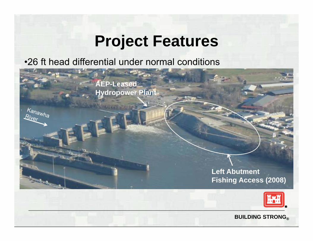
Project Features
Left Abutment Fishing Access (2008)
•26 ft head differential under normal conditions
AEP-LeasedHydropower Plant

BUILDING STRONG®
1937 Left Abutment Plan View
Location of 75 ft long steelsheet pile cutoff
Upstream and downstreamsteel cofferdam cells
Hydropower facility

BUILDING STRONG®
1937: Left abutment bank soils excavated during constructionNote 10 to 20 ft thick layer of fine silty sand

BUILDING STRONG®
1936: Sandstone blocks used for D/S slope protection

BUILDING STRONG®
2008 Fishing Access Reconstruction
Original design plan:► 800-ft long concrete fishing access ramp D/S of
hydropower plant► Stone slope protection below fishing access ramp► Excavation and planting of vegetation above fishing
access ramp► Contractor to work incrementally to avoid slope
failures (no more than 50 ft excavated at a time)

BUILDING STRONG®
During 2008 Construction
Contractor cleared/grubbed/excavated 400-ft reach at once Resulted in rapid bank sloughing, localized
slope failures, and piping progression

BUILDING STRONG®
2008 Construction
Failed soil mass
Piping of fine silty sand

BUILDING STRONG®
2008 Emergency Actions
Subsequent piping and collapse of bank soils
Excavation of failed soilsTrench drain installation

BUILDING STRONG®
2008 Emergency Actions

BUILDING STRONG®
2008 Emergency Actions
Continued seepage during and following construction

BUILDING STRONG®
Seepage Around Left AbutmentFLOW

BUILDING STRONG®
Post-2008 Emergency Actions 2008 emergency actions recognized as IRRM
(not long-term solution) USACE hired consultant in 2009 to perform
investigations offer remedial alternatives► Borings and PZs► Dye testing and water quality testing► Weir► Numerical modeling

BUILDING STRONG®
Left abutment soil profile
2009 Investigations
•Dye Testing:U/S to D/S connection w/ pool
•Borings & lab testing:20-25 ft thick layer of uniform fine sand
UPPER AQUIFER
LOWER AQUIFER
Cu ranging from 2.3 to 8.1 (median 3.8) – Highly susceptible to piping

BUILDING STRONG®
Major findings and recommendations► Continued seepage and soil erosion could eventually
lead to a flanking failure of the left abutment► Suggested increased site monitoring► Four remedial concepts presented
• Seepage cutoff wall• Flatten slope and graded filter• Retaining structure at toe of slope, flatten slope, graded filter• Use walkway as retaining structure and graded filter
2010 Consultant Report

BUILDING STRONG®
Observations since 2010
Continued seepage transporting fine silty sand New weir to monitor seepage flows Seepage at weir measured around 22 gpm (not all
seepage captured by weir)
Seepage collection box Transport of fine sand under normal conditions

BUILDING STRONG®
Observations since 2010
Enlargement of 3 subsidence features along slope

BUILDING STRONG®
Remediation Plan
2014: FERC directed AEP to address left abutment seepage for facility relicensing
AEP hired consultant to design seepage remediation plan – STEEL SHEET PILE CUTOFF WALL PROPOSED
USACE performed reviews (additional analyses) and provided input on proposed plan

BUILDING STRONG®
Proposed Cutoff Wall Geometry

BUILDING STRONG®
Piping Initiation: Critical Horizontal Gradient Kovacs theory for piping initiation
=
FEM Output

BUILDING STRONG®
Piping Progression: Critical Horizontal Gradients
Bligh’s Creep Ratio: For safety against piping, H/L < 1/C, where C is a soil coefficient
For this site: H/L ranging from 0.02 to 0.08 C = 15; 1/C = 0.07 Progressive erosion possible based on creep ratios

BUILDING STRONG®
Sellmeijer (2011), Schmertmann (2000), and Hoffmans (2013) theories for piping progression
Piping Progression: Critical Horizontal Gradients
Sellmeijer Equation:
Schmertmann Equation:
Hoffmans Equation:

BUILDING STRONG®
Piping Progression: Critical Horizontal Gradients
Summary of Critical Horizontal Gradients for Pipe Advancement
Soil Gradation Band
Evaluation Method
Sellmeijer Schmertmann Hoffmans
iadv iadv iadv
Coarse Band (Cu = 6.13) 0.049 0.046 0.088
Fine Band (Cu = 2.32) 0.022 0.045 0.088
Average Band (Cu = 4.13) 0.033 0.044 0.057

BUILDING STRONG®
Calculated Gradients from Site Piezometers
Observed gradients in the range of calculated critical gradients from Sellmeijer, Schmertmann, and Kovacs theories

BUILDING STRONG®
Prediction of Required Cutoff Length

BUILDING STRONG®
Prediction of Required Cutoff Length

BUILDING STRONG®
Selected Plan

BUILDING STRONG®
Selected Plan – Completed June 2015

BUILDING STRONG®
Post-construction Monitoring

BUILDING STRONG®
Post-construction Monitoring

BUILDING STRONG®
Additional monitoring:► Lidar scan of bank (enlargement of subsidence
features)► Piezometer trends► Seepage outflow► Dye testing
Post-construction Monitoring

BUILDING STRONG®
Conclusions
Provides general awareness of potential problems with seepage through soil abutments
Good case study to compare against current piping progression theory► Agreement between theoretical and observed gradients
Need for more full-scale studies which focus on critical gradients for piping progression
Cutoff completed June 2015► Providing risk reduction based on preliminary data/observations► Continue to monitor site and evaluate data to determine
effectiveness

BUILDING STRONG®
Questions?Kevin ButlerGeotechnical Engineering SectionUSACE Huntington District