“Woodpile Mission” Valle San Giovanni Abruzzo Italy December 2007.
Majlesi Journal of Electrical Engineering Vol. 13, No. 1, March 2019
37
Wine Glass Shaped Microstrip Antenna with Woodpile
Structure for Wireless Applications
Rajshri C. Mahajan1*, Vibha Vyas2
1- Department of Electronics and Telecommunication Engineering, College of Engineering Pune, Pune, India.
Email: [email protected] (Corresponding author)
2- Department of Electronics and Telecommunication Engineering, College of Engineering Pune, Pune, India.
Email: [email protected]
Received: May 2018 Revised: July 2018 Accepted: September 2018
ABSTRACT:
The hexagonal shaped slotted Wine glass shaped Co Planar Waveguide (CPW) fed antenna for wireless applications is
proposed in this paper. The Woodpile based Electronic Bandgap (EBG) structure is used as linked ground surface for
bandwidth and gain enhancement. The performance characteristics of different sized strip widths of woodpile structures
with wine glass shaped antenna have carried out; the antenna resonates in the band of 2GHz, 5 GHz, and 7 GHz. The
band width enhancement of 43 % and gain of 9 dB at 1.9910 GHz for 1mm strip width of woodpile has observed. In
addition, the group delay variation and E –plane co and cross polarization radiation patterns for various strip widths of
woodpile structure have obtained. The group delay is maintained less than 5 nanosecond and there is a significant
difference between co and cross polarization for E- plane radiation patterns for 1mm strip width of woodpile structure.
The antenna is fabricated with hexagonal slot and 1mm strip width woodpile structure and tested for return loss and
radiation pattern.
KEYWORDS: CPW Fed Antenna, Electronic Band Gap Structure, Wood Pile Structure.
1. INTRODUCTION
Mobile radio and wireless communications are the
areas of research now-a-days. Micro strip antennas meet
all the requirements for these communications. These
antennas are low profile, conformal to planar and non-
planar surfaces, compatible with MMIC designs. Also,
when a particular patch shape and mode are selected,
resonant frequency, polarization radiation pattern and
impedance can be obtained according to application and
necessity [1].
Fig. 1. Coplanar Waveguide Structure (CPW).
The performance characteristics of antenna also
depend on the type of signal inputting or feeding
techniques. There are four major techniques for feeding
micro strip antenna like coaxial feeding, micro strip line
feeding, aperture feeding and inset feeding. Among all
these, CPW (Coplanar Waveguide) feeding is easy to
fabricate, simple to match with Micro-strip antenna by
controlling the inset position and simple to model
electrically. CPW feeding consists of a center metallic
strip which carries signal from feed location to
microstrip antenna and two side plane conductors which
act as ground surface. Fig.1 shows the construction of
CPW feeding with side ground planes.
The microstrip patch, CPW line and ground surfaces
are printed on one side of substrate. The directivity of
this antenna can be increased by printing partial or
complete ground plane on another side (back side) of the
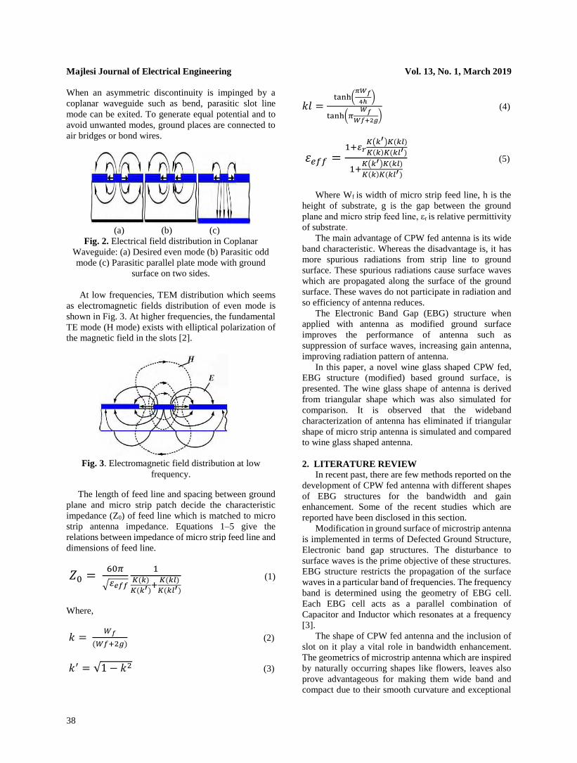
substrate. The electric field lines in coplanar fed
waveguide are shown in Fig. 2. The field lines for
grounded and ungrounded waveguide forming different
modes are explained. The CPW comprises of three
conductors with different potentials. Transmission line
theory for a three-wire system is used to explain even
and odd mode solutions as illustrated in Fig. 2. The
coplanar mode which is also called as desired even mode
[Fig. 2 (a)] consists of ground planes at both sides of the
center strip, whereas the slot line mode [Fig. 2 (b)], also
called as parasitic odd mode, consists of opposite
electrode potentials. When the bottom side of the
substrate is metalized, a zero-cutoff frequency with
additional parasitic parallel plate mode exists [Fig. 2(c)].
Majlesi Journal of Electrical Engineering Vol. 13, No. 1, March 2019
38
When an asymmetric discontinuity is impinged by a
coplanar waveguide such as bend, parasitic slot line
mode can be exited. To generate equal potential and to
avoid unwanted modes, ground places are connected to
air bridges or bond wires.
(a) (b) (c)
Fig. 2. Electrical field distribution in Coplanar
Waveguide: (a) Desired even mode (b) Parasitic odd
mode (c) Parasitic parallel plate mode with ground
surface on two sides.
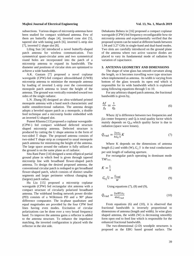
At low frequencies, TEM distribution which seems
as electromagnetic fields distribution of even mode is
shown in Fig. 3. At higher frequencies, the fundamental
TE mode (H mode) exists with elliptical polarization of
the magnetic field in the slots [2].
Fig. 3. Electromagnetic field distribution at low
frequency.
The length of feed line and spacing between ground
plane and micro strip patch decide the characteristic
impedance (Z0) of feed line which is matched to micro
strip antenna impedance. Equations 1–5 give the
relations between impedance of micro strip feed line and
dimensions of feed line.
𝑍0 = 60𝜋
√𝜀𝑒𝑓𝑓
1𝐾(𝑘)
𝐾(𝑘′)+
𝐾(𝑘𝑙)
𝐾(𝑘𝑙′)
(1)
Where,
𝑘 = 𝑊𝑓
(𝑊𝑓+2𝑔) (2)
𝑘′ = √1 − 𝑘2 (3)
𝑘𝑙 =tanh(
𝜋𝑊𝑓
4ℎ)
tanh(𝜋𝑊𝑓
𝑊𝑓+2𝑔) (4)
𝜀𝑒𝑓𝑓 =1+𝜀𝑟
𝐾(𝑘′)𝐾(𝑘𝑙)
𝐾(𝑘)𝐾(𝑘𝑙′)
1+𝐾(𝑘′)𝐾(𝑘𝑙)
𝐾(𝑘)𝐾(𝑘𝑙′)
(5)
Where Wf is width of micro strip feed line, h is the
height of substrate, g is the gap between the ground
plane and micro strip feed line, εr is relative permittivity
of substrate.
The main advantage of CPW fed antenna is its wide
band characteristic. Whereas the disadvantage is, it has
more spurious radiations from strip line to ground
surface. These spurious radiations cause surface waves
which are propagated along the surface of the ground
surface. These waves do not participate in radiation and
so efficiency of antenna reduces.
The Electronic Band Gap (EBG) structure when
applied with antenna as modified ground surface
improves the performance of antenna such as
suppression of surface waves, increasing gain antenna,
improving radiation pattern of antenna.
In this paper, a novel wine glass shaped CPW fed,
EBG structure (modified) based ground surface, is
presented. The wine glass shape of antenna is derived
from triangular shape which was also simulated for
comparison. It is observed that the wideband
characterization of antenna has eliminated if triangular
shape of micro strip antenna is simulated and compared
to wine glass shaped antenna.
2. LITERATURE REVIEW
In recent past, there are few methods reported on the
development of CPW fed antenna with different shapes
of EBG structures for the bandwidth and gain
enhancement. Some of the recent studies which are
reported have been disclosed in this section.
Modification in ground surface of microstrip antenna
is implemented in terms of Defected Ground Structure,
Electronic band gap structures. The disturbance to
surface waves is the prime objective of these structures.
EBG structure restricts the propagation of the surface
waves in a particular band of frequencies. The frequency
band is determined using the geometry of EBG cell.
Each EBG cell acts as a parallel combination of
Capacitor and Inductor which resonates at a frequency
[3].
The shape of CPW fed antenna and the inclusion of
slot on it play a vital role in bandwidth enhancement.
The geometrics of microstrip antenna which are inspired
by naturally occurring shapes like flowers, leaves also
prove advantageous for making them wide band and
compact due to their smooth curvature and exceptional
Majlesi Journal of Electrical Engineering Vol. 13, No. 1, March 2019
39
subsections. Various shapes of microstrip antennas have
been studied for compact wideband antenna. Few of
them are butterfly shape [4], inverted cone slot [5],
tapered slot with tuning patch [6], inverted L-strip slot
[7], inverted U shape slot [8].
Liling Sun [4] introduced a novel butterfly-shaped
patch antenna for wireless communication. Two
symmetrical quasi-circular arms and two symmetrical
round holes are incorporated into the patch of a
microstrip antenna to expand its bandwidth. The
diameter and positions of circular slots are optimized to
achieve a wide bandwidth.
A.K. Gautam [7] proposed a novel coplanar
waveguide (CPW)-fed compact ultrawideband (UWB)
microstrip antenna to minimize the monopole antenna
by loading of inverted L-strip over the conventional
monopole patch antenna to lower the height of the
antenna. The ground was vertically extended toward two
sides of the single radiator.
L.N. Zhang [8] designed an ultra-wideband printed
monopole antenna with a band notch characteristic and
stable omnidirectional radiation. The antenna design
adopts a beveled square patch as a monopole, a double
feed technique and a microstrip feeder embedded with
an inverted U-shaped slot.
Puneet Khanna [13] proposed a coplanar waveguide-
(CPW-) fed compact wideband defected structure
shaped microstrip antenna. Defected structure is
produced by cutting the U shape antenna in the form of
two-sided T shape. The proposed antenna consists of
two-sided T shape strip as compared to usual monopole
patch antenna for minimizing the height of the antenna.
The large space around the radiator is fully utilized as
the ground is on the same plane as of radiator.
Situ Rani Patre [14] designed a semi-elliptical partial
ground plane in which feed is given through tapered
microstrip line with broadband flower-shaped patch
antenna. To design the desired proposed antenna, the
conventional circular patch is reshaped to get broadband
flower-shaped patch, which consists of distinct smaller
segments and larger perimeter without changing the
(largest) patch radius.
Hu Liu [15] proposed a microstrip coplanar
waveguide (CPW) fed rectangular slot antenna with a
compact structure of circularly polarized broadband
antenna. The wideband feeding network power divider
(PD) consists of a Wilkinson PD and a 90° phase
difference comparator. The in-phase quadrature and
equal magnitudes are provided by the four CPW feed
lines having even modes. Excitation of circular
polarizations can be done over a very broad frequency
band. To improve the antenna gains a reflector is added
to the antenna structure. To enhance the impedance
matching, the inverted configuration is placed with the
reflector in the slot side.
Debakanta Behera in [16] proposed a compact coplanar
waveguide (CPW) fed frequency reconfigurable bow-tie
microstrip antenna and experimentally verified that the
proposed system can be tuned at different bands between
1.94 and 3.27 GHz in single-band and dual-band modes.
Two slots are carefully introduced on the ground plane
of the antenna where two active varactor diodes are
placed to vary its fundamental mode of radiation by
variation of capacitance.
3. ANTENNA GEOMETRY AND DIMENSIONS
The shape of wine glass has smooth curvature along
the length, so it becomes travelling wave type structure
when implemented as antenna. Its width is varying from
bottom of the glass towards its open end which is
responsible for its wide bandwidth which is explained
using following equations through 5 to 10.
For any arbitrary shaped patch antenna, the fractional
bandwidth is given by,
∆𝑓
𝑓0=
1
𝑄𝑡 (6)
Where Δf is difference between two frequencies and
f0is center frequency and Qt is total quality factor which
mainly depends on Qrad which quality factor is due to
radiation (space wave losses).
𝑄𝑟𝑎𝑑 =2𝜔𝜀𝑟
ℎ𝐺𝑡 𝑙⁄𝐾 (7)
Where K depends on the dimensions of antenna
length (L) and width (W), lGt is the total conductance
per unit length of radiating aperture.
For rectangular patch operating in dominant mode
TMx010 ,
𝐾 =𝐿
4 (8)
𝐺𝑡 𝑙 =𝐺𝑟𝑎𝑑
𝑊⁄ (9)
Using equations (7), (8) and (9),
𝑄𝑟𝑎𝑑 =2𝜔𝑊𝐿𝜀𝑟
4ℎ𝐺𝑟𝑎𝑑 (10)
From equations (6) and (10), it is observed that
fractional bandwidth is inversely proportional to
dimensions of antenna (length and width). In wine glass
shaped antenna, the width (W) is decreasing smoothly
form open end to feed line which is responsible for the
enhanced fractional bandwidth.
The two-dimensional (2-D) woodpile structures is
proposed as the EBG based ground surface. The
Majlesi Journal of Electrical Engineering Vol. 13, No. 1, March 2019
40
dimensions of woodpile strips are varied for parametric
study of their effects on antenna parameters. Also, the
slot is engraved in the antenna structure to increase the
bandwidth of antenna.
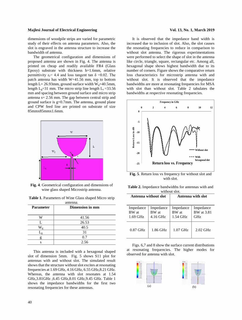
The geometrical configuration and dimensions of
proposed antenna are shown in Fig. 4. The antenna is
printed on cheap and readily available FR4 (Glass
Epoxy) substrate with thickness h=1.6mm, relative
permittivity εr= 4.4 and loss tangent tan δ =0.02. The
patch antenna has width W=41.56 mm, top to bottom
length L= 26.93mm, ground surface width Wg=40.5mm,
length Lg=31 mm. The micro strip line length Ls =33.56
mm and spacing between ground surface and micro strip
antenna s= 2.56 mm. The gap between central strip and
ground surface is g=0.7mm. The antenna, ground plane
and CPW feed line are printed on substrate of size
85mmx85mmx1.6mm.
Fig. 4. Geometrical configuration and dimensions of
wine glass shaped Microstrip antenna.
Table 1. Parameters of Wine Glass shaped Micro strip
antenna.
Parameter Dimension in mm
W 41.56
L 26.53
Wg 40.5
Lg 31
g 0.7
s 2.56
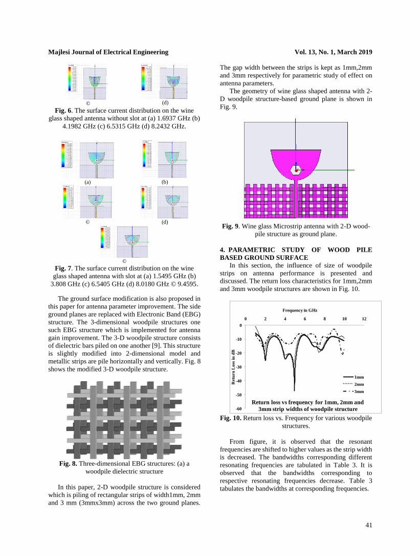
This antenna is included with a hexagonal shaped
slot of dimension 5mm. Fig. 5 shows S11 plot for
antennas with and without slot. The simulated result
shows that the structure without slot excites at resonating
frequencies at 1.69 GHz, 4.16 GHz, 6.55 GHz,8.21 GHz.
Whereas, the antenna with slot resonates at 1.54
GHz,3.81GHz ,6.45 GHz,8.01 GHz,9.45 GHz. Table 1
shows the impedance bandwidths for the first two
resonating frequencies for these antennas.
It is observed that the impedance band width is
increased due to inclusion of slot. Also, the slot causes
the resonating frequencies to reduce in comparison to
without slot antenna. The rigorous experimentations
were performed to select the shape of slot in the antenna
like circle, triangle, square, rectangular etc. Among all,
hexagonal shape shows highest bandwidth due to its
number of corners. Figure shows the comparative return
loss characteristics for microstrip antenna with and
without slot. It is observed that the impedance
bandwidths are more at resonating frequencies for MSA
with slot than without slot. Table 2 tabulates the
bandwidths at respective resonating frequencies.
Fig. 5. Return loss vs frequency for without slot and
with slot.
Table 2. Impedance bandwidths for antennas with and
without slot.
Antenna without slot
Antenna with slot
Impedance
BW at
1.69 GHz
Impedance
BW at
4.16 GHz
Impedance
BW at
1.54 GHz
Impedance
BW at 3.81
GHz
0.87 GHz
1.86 GHz 1.07 GHz 2.02 GHz
Figs. 6,7 and 8 show the surface current distributions
at resonating frequencies. The higher modes for
observed for antenna with slot.
(a)
(b)
-25
-20
-15
-10
-5
0
0 2 4 6 8 10 12
Retu
rn
Loss
in
dB
Frequency in GHz
Return loss vs. Frequency
Without slot
With
hexagonal slot
Majlesi Journal of Electrical Engineering Vol. 13, No. 1, March 2019
41
©
(d)
Fig. 6. The surface current distribution on the wine
glass shaped antenna without slot at (a) 1.6937 GHz (b)
4.1982 GHz (c) 6.5315 GHz (d) 8.2432 GHz.
(a)
(b)
©
(d)
©
Fig. 7. The surface current distribution on the wine
glass shaped antenna with slot at (a) 1.5495 GHz (b)
3.808 GHz (c) 6.5405 GHz (d) 8.0180 GHz © 9.4595.
The ground surface modification is also proposed in
this paper for antenna parameter improvement. The side
ground planes are replaced with Electronic Band (EBG)
structure. The 3-dimensional woodpile structures one
such EBG structure which is implemented for antenna
gain improvement. The 3-D woodpile structure consists
of dielectric bars piled on one another [9]. This structure
is slightly modified into 2-dimensional model and
metallic strips are pile horizontally and vertically. Fig. 8
shows the modified 3-D woodpile structure.
Fig. 8. Three-dimensional EBG structures: (a) a
woodpile dielectric structure
In this paper, 2-D woodpile structure is considered
which is piling of rectangular strips of width1mm, 2mm
and 3 mm (3mmx3mm) across the two ground planes.
The gap width between the strips is kept as 1mm,2mm
and 3mm respectively for parametric study of effect on
antenna parameters.
The geometry of wine glass shaped antenna with 2-
D woodpile structure-based ground plane is shown in
Fig. 9.
Fig. 9. Wine glass Microstrip antenna with 2-D wood-
pile structure as ground plane.
4. PARAMETRIC STUDY OF WOOD PILE
BASED GROUND SURFACE
In this section, the influence of size of woodpile
strips on antenna performance is presented and
discussed. The return loss characteristics for 1mm,2mm
and 3mm woodpile structures are shown in Fig. 10.
Fig. 10. Return loss vs. Frequency for various woodpile
structures.
From figure, it is observed that the resonant
frequencies are shifted to higher values as the strip width
is decreased. The bandwidths corresponding different
resonating frequencies are tabulated in Table 3. It is
observed that the bandwidths corresponding to
respective resonating frequencies decrease. Table 3
tabulates the bandwidths at corresponding frequencies.
-60
-50
-40
-30
-20
-10
0
0 2 4 6 8 10 12
Ret
urn
Lo
ss i
n d
B
Frequency in GHz
Return loss vs frequency for 1mm, 2mm and
3mm strip widths of woodpile structure
1mm
2mm
3mm
Majlesi Journal of Electrical Engineering Vol. 13, No. 1, March 2019
42
Table 3. Impedance bandwidths for various strip
widths of woodpile structure.
Antenna
Type
Resonant
Frequenc
y in
GHz
Bandwidth at
Resonant
Frequency in
GHz
%
Band
width
Antenna with
1mm
woodpile
structure
1.9910 0.8649 43.44
4.9459 2.1622 43.71
7.6847 2.0360 26.49
Antenna with
2mm
woodpile
structure
1.8739 0.7477 39.90
4.8649 2.0 41.11
7.3964 1.8649 25.21
Antenna with
3mm
woodpile
structure
1.8018 0.8739 48.50
4.4955 1.3694 30.46
7.4234 0.5135 6.91
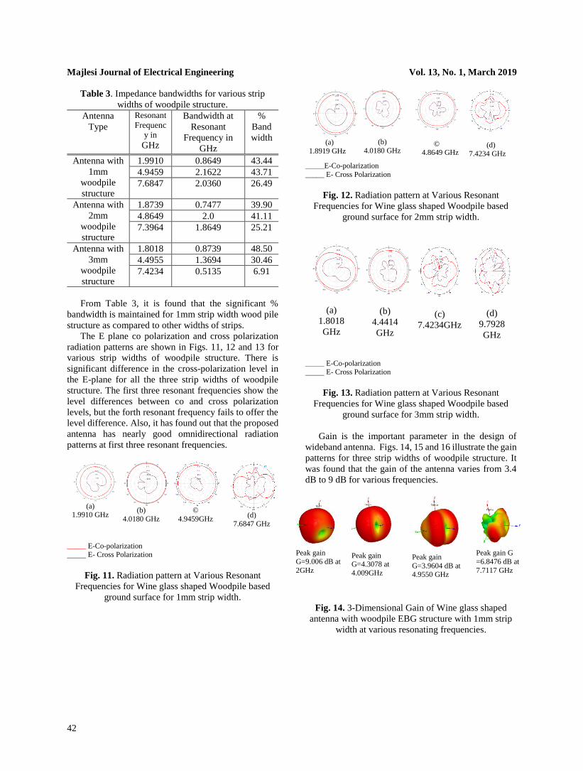
From Table 3, it is found that the significant %
bandwidth is maintained for 1mm strip width wood pile
structure as compared to other widths of strips.
The E plane co polarization and cross polarization
radiation patterns are shown in Figs. 11, 12 and 13 for
various strip widths of woodpile structure. There is
significant difference in the cross-polarization level in
the E-plane for all the three strip widths of woodpile
structure. The first three resonant frequencies show the
level differences between co and cross polarization
levels, but the forth resonant frequency fails to offer the
level difference. Also, it has found out that the proposed
antenna has nearly good omnidirectional radiation
patterns at first three resonant frequencies.
(a)
1.9910 GHz
(b)
4.0180 GHz
©
4.9459GHz
(d)
7.6847 GHz
_____ E-Co-polarization E- Cross Polarization
Fig. 11. Radiation pattern at Various Resonant
Frequencies for Wine glass shaped Woodpile based
ground surface for 1mm strip width.
(a)
1.8919 GHz
(b)
4.0180 GHz
© 4.8649 GHz
(d)
7.4234 GHz
_____E-Co-polarization
_____ E- Cross Polarization
Fig. 12. Radiation pattern at Various Resonant
Frequencies for Wine glass shaped Woodpile based
ground surface for 2mm strip width.
(a)
1.8018
GHz
(b)
4.4414
GHz
(c)
7.4234GHz
(d)
9.7928
GHz
_____ E-Co-polarization E- Cross Polarization
Fig. 13. Radiation pattern at Various Resonant
Frequencies for Wine glass shaped Woodpile based
ground surface for 3mm strip width.
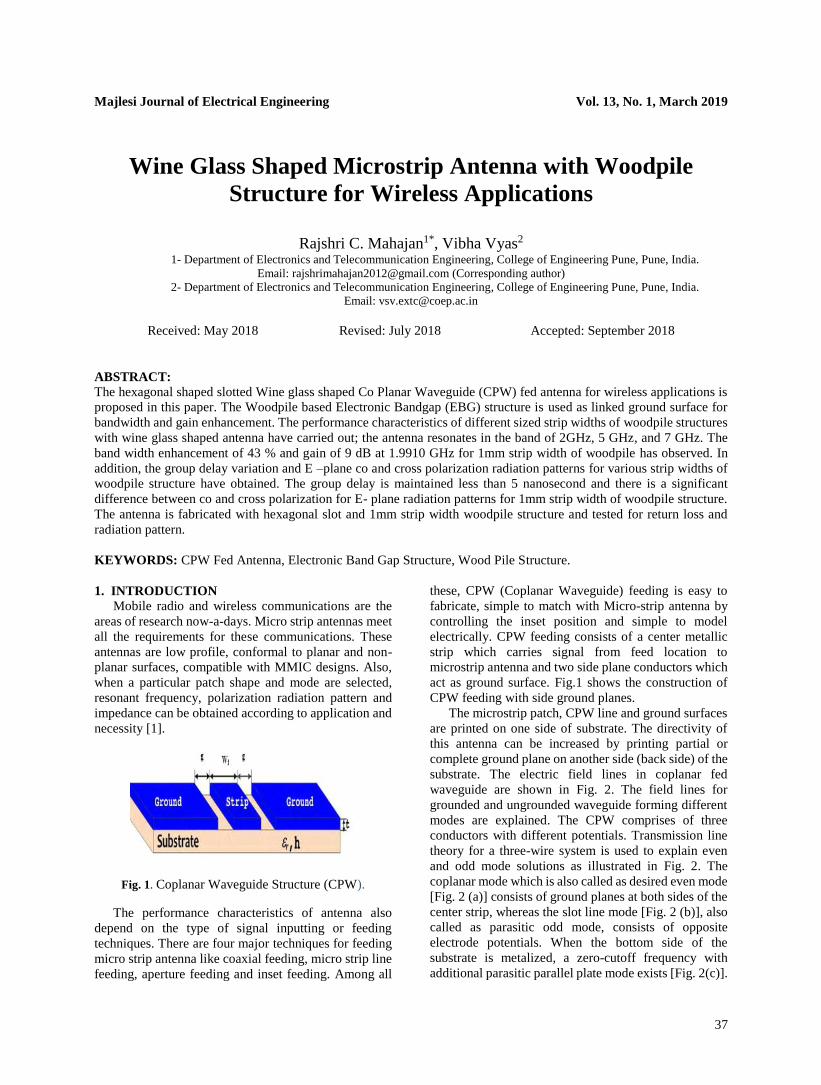
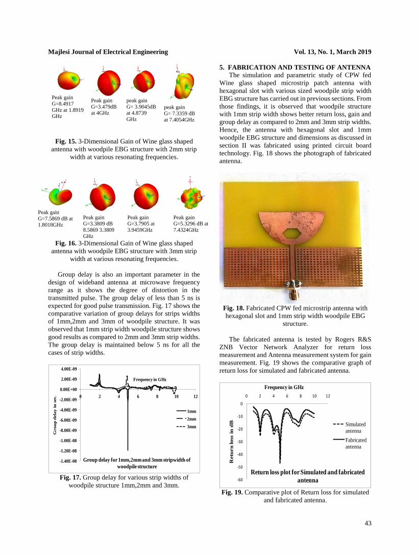
Gain is the important parameter in the design of
wideband antenna. Figs. 14, 15 and 16 illustrate the gain
patterns for three strip widths of woodpile structure. It
was found that the gain of the antenna varies from 3.4
dB to 9 dB for various frequencies.
Peak gain
G=9.006 dB at
2GHz
Peak gain G=4.3078 at
4.009GHz
Peak gain
G=3.9604 dB at 4.9550 GHz
Peak gain G
=6.8476 dB at
7.7117 GHz
Fig. 14. 3-Dimensional Gain of Wine glass shaped
antenna with woodpile EBG structure with 1mm strip
width at various resonating frequencies.
Majlesi Journal of Electrical Engineering Vol. 13, No. 1, March 2019
43
Peak gain
G=8.4917
GHz at 1.8919 GHz
Peak gain
G=3.479dB at 4GHz
peak gain
G= 3.9045dB at 4.8739
GHz
peak gain
G= 7.3359 dB
at 7.4054GHz
Fig. 15. 3-Dimensional Gain of Wine glass shaped
antenna with woodpile EBG structure with 2mm strip
width at various resonating frequencies.
Peak gain
G=7.5869 dB at 1.8018GHz
Peak gain G=3.3809 dB
8.5869 3.3809
GHz
Peak gain G=3.7905 at
3.9459GHz
Peak gain G=5.3296 dB at
7.4324GHz
Fig. 16. 3-Dimensional Gain of Wine glass shaped
antenna with woodpile EBG structure with 3mm strip
width at various resonating frequencies.
Group delay is also an important parameter in the
design of wideband antenna at microwave frequency
range as it shows the degree of distortion in the
transmitted pulse. The group delay of less than 5 ns is
expected for good pulse transmission. Fig. 17 shows the
comparative variation of group delays for strips widths
of 1mm,2mm and 3mm of woodpile structure. It was
observed that 1mm strip width woodpile structure shows
good results as compared to 2mm and 3mm strip widths.
The group delay is maintained below 5 ns for all the
cases of strip widths.
Fig. 17. Group delay for various strip widths of
woodpile structure 1mm,2mm and 3mm.
5. FABRICATION AND TESTING OF ANTENNA
The simulation and parametric study of CPW fed
Wine glass shaped microstrip patch antenna with
hexagonal slot with various sized woodpile strip width
EBG structure has carried out in previous sections. From
those findings, it is observed that woodpile structure
with 1mm strip width shows better return loss, gain and
group delay as compared to 2mm and 3mm strip widths.
Hence, the antenna with hexagonal slot and 1mm
woodpile EBG structure and dimensions as discussed in
section II was fabricated using printed circuit board
technology. Fig. 18 shows the photograph of fabricated
antenna.
Fig. 18. Fabricated CPW fed microstrip antenna with
hexagonal slot and 1mm strip width woodpile EBG
structure.
The fabricated antenna is tested by Rogers R&S
ZNB Vector Network Analyzer for return loss
measurement and Antenna measurement system for gain
measurement. Fig. 19 shows the comparative graph of
return loss for simulated and fabricated antenna.
Fig. 19. Comparative plot of Return loss for simulated
and fabricated antenna.
-1.40E-08
-1.20E-08
-1.00E-08
-8.00E-09
-6.00E-09
-4.00E-09
-2.00E-09
0.00E+00
2.00E-09
4.00E-09
0 2 4 6 8 10 12
Gro
up
dela
y i
n s
ec.
Frequency in GHz
Group delay for 1mm,2mm and 3mm stripwidth of
woodpile structure
1mm
2mm
3mm
-60
-50
-40
-30
-20
-10
0
0 2 4 6 8 10 12
Retu
rn
lo
ss i
n d
B
Frequency in GHz
Return loss plot for Simulated and fabricated
antenna
Simulated antenna
Fabricated antenna
Majlesi Journal of Electrical Engineering Vol. 13, No. 1, March 2019
44
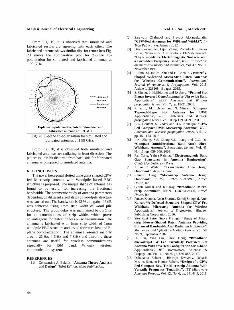
From Fig. 19, it is observed that simulated and
fabricated results are agreeing with each other. The
fabricated antenna shows similar dips for return loss.Fig.
20 shows the comparative plot for E-plane co-
polarization for simulated and fabricated antennas at
1.99 GHz.
Fig. 20. E-plane co-polarization for simulated and
fabricated antennas at 1.99 GHz.
From Fig. 20, it is observed both simulated and
fabricated antennas are radiating in front direction. The
pattern is little bit distorted from back side for fabricated
antenna as compared to simulated antenna.
6. CONCLUSION
The novel hexagonal slotted wine glass shaped CPW
fed Microstrip antenna with Woodpile based EBG
structure is proposed. The unique shape of antenna has
found to be useful for increasing the fractional
bandwidth. The parametric study of antenna parameters
depending on different sized strips of woodpile structure
was carried out. The bandwidth is 43 % and gain of 9 dB
was achieved using 1mm strip width of wood pile
structure. The group delay was maintained below 5 ns
for all combinations of strip widths which prove
advantageous for distortion less pulse transmission. The
antenna is fabricated with 1mm strip width of 1mm
woodpile EBG structure and tested for return loss and E-
plane co-polarization. The antennae resonate majorly
around 2GHz, 4 GHz and 7 GHz and therefore these
antennas are useful for wireless communications
especially for ISM band, Wi-max wireless
communication systems.
REFERENCES [1] Constantine A. Balanis, “Antenna Theory Analysis
and Design”, Third Edition, Wiley Publication.
[2] Sarawuth Chaimool and Prayoot Akkaraekthalin,
“CPW-Fed Antennas for WiFi and WiMAX”, In-
Tech Publication, January 2012
[3] Dan Sievenpiper, Lijun Zhang, Romulo F. Jimenez
Broas, Nicholas G. Alex´opolous, Eli Yablonovitch,
“High-Impedance Electromagnetic Surfaces with
a Forbidden Frequency Band”, IEEE transactions
on microwave theory and techniques, Vol. 47, No. 11,
November 1999.
[4] L. Sun, M. He ,Y. Zhu and H. Chen, “A Butterfly-
Shaped Wideband Micro-Strip Patch Antennas
for Wireless Communications”, International
Journal of Antennas & Propagation, Vol. 2015,
Article Id 328208 , 8 pages, 2015.
[5] S. Cheng, P. Hallbjorner and Rydberg, “Printed Slot
Planar Inverted Cone Antenna for Ultrawide Band
Applications”, IEEE Antennas and Wireless
propagation letters, Vol. 7, pp. 18-21, 2008.
[6] R. azim, M.T. Islam and N. Misran, “Compact
Tapered-Shape Slot Antenna for UWB
Applications”, IEEE Antennas and Wireless
propagation letters, Vol.10, pp.1190-1193, 2011.
[7] A.K. Gautam, S. Yadav and B.K. Kanaujia, “CPW
Fed Compact UWB Microstrip Antenna”, IEEE
Antennas and Wireless propagation letters, Vol. 12,
pp. 151-154, 2013.
[8] L.N. Zhang, S.S. Zhong,X.L. Liang and C.Z. Du,
“Compact Omnidirectional Band Notch Ultra-
Wideband Antenna”, Electronics Letters, Vol. 45,
No. 13, pp. 659-660, 2009.
[9] Fan Yang, Yahya Rahmat, “Electromagnetic Band
Gap Structures in Antenna Engineering”, Cambridge University Press.
[10] Brian C Wadell, “Transmission Line Design
Handbook”, Artech House.
[11] Ramesh Garg, “Microstrip Antenna Design
Handbook”, ISBN-13 978-0-521-88991-9, Artech
House, Inc
[12] Girish Kumar and K.P.Ray, “Broadband Micro-
Strip Antennas”, ISBN- 1-58053-244-6, Artech
House, Inc
[13] Puneet Khanna, Amar Sharma, Kshitij Shinghal, Arun
Kumar, “A Defected Structure Shaped CPW-Fed
Wideband Microstrip Antenna for Wireless
Applications”, Journal of Engineering, Hindawi
Publishing Corporation, 2016.
[14] Situ Rani Patre, Surya P.Singh, “Study of Micro
strip Flower–Shaped Patch Antenna Providing
Enhanced Bandwidth And Radiation Efficiency”, Microwave and Optical Technology Letters, Vol. 58,
No. 9, September 2016.
[15] Hu Liu, Ying Liu, Shuxi Gong, “Broadband
microstrip-CPW Fed Circularly Polarised Slot
Antenna With Inverted Configuration for L-band
Applications”, IET Microwaves, Antennas &
Propagation, Vol. 11, No. 6, pp. 880-885, 2017.
[16] Debakanta Behera , Biswajit Dwivedy, Debasis
Mishra, Santanu Kumar Behera, “Design of a CPW
Fed Compact Bow-Tie Microstrip Antenna With
Versatile Frequency Tenability”, IET Microwave
Antennas Propag., Vol. 12, No. 6, pp. 841-849, 2018.
0
5
10
15
20
25
E-plane Co-polarization plots for Simulated and
fabricated antenna at 1.99 GHz
Simulated
antenna
Fabricated
antenna