Windows Server 2003 Structure and Architecture - Pearson...
44
25 The underlying operating system structure and the relationship of component parts are fundamental to deploying and managing Windows Server 2003 environ- ments. By understanding the operating system architecture, the system adminis- trator should be in a better position to install, configure, optimize, and troubleshoot Windows Server 2003. This chapter is an architectural overview of Windows Server 2003. After reading it, you should have the following: • An understanding of the operating system’s structural layers, subsystems, and managers, including the executive kernel modes and user modes, subsystems, and managers • A working knowledge of Windows Server 2003 process management, includ- ing multitasking, the interplay of processes and threads, process viewing, and management tools • A perspective on physical and virtual memory management • A basic understanding of the boot process • A working grasp of the registry’s function and structure • An understanding of application dependencies and software compatibility with Windows Server 2003 through the use of its tools There have been relatively very few underlying architectural changes made from Windows 2000. However, there are a number of enhancements that will have a beneficial impact on administration. Chapter 2 Windows Server 2003 Structure and Architecture 3930 P-02 3/12/03 9:53 AM Page 25
Transcript of Windows Server 2003 Structure and Architecture - Pearson...

25
The underlying operating system structure and the relationship of componentparts are fundamental to deploying and managing Windows Server 2003 environ-ments. By understanding the operating system architecture, the system adminis-trator should be in a better position to install, configure, optimize, and troubleshootWindows Server 2003. This chapter is an architectural overview of Windows Server2003. After reading it, you should have the following:
• An understanding of the operating system’s structural layers, subsystems, andmanagers, including the executive kernel modes and user modes, subsystems,and managers
• A working knowledge of Windows Server 2003 process management, includ-ing multitasking, the interplay of processes and threads, process viewing, andmanagement tools
• A perspective on physical and virtual memory management
• A basic understanding of the boot process
• A working grasp of the registry’s function and structure
• An understanding of application dependencies and software compatibilitywith Windows Server 2003 through the use of its tools
There have been relatively very few underlying architectural changes madefrom Windows 2000. However, there are a number of enhancements that will havea beneficial impact on administration.
Chapter
2 Windows Server 2003 Structure and Architecture
3930 P-02 3/12/03 9:53 AM Page 25
STRUCTURAL MODES, SUBSYSTEMS, AND MANAGERS
A surface view of the Windows Server 2003 structure reveals an eloquently simplearrangement of functions that separates system-related events from user-relatedevents. As you move deeper into the components of Windows Server 2003, youwill see that Microsoft has designed a very compartmentalized operating system.In this section we will review:
• The structural layers of the kernel mode, the Hardware Abstraction Layer(HAL), and the user mode
• The role of the Windows Server 2003 executive mode and its managers
• The role of the Windows Server 2003 user mode and its subsystems
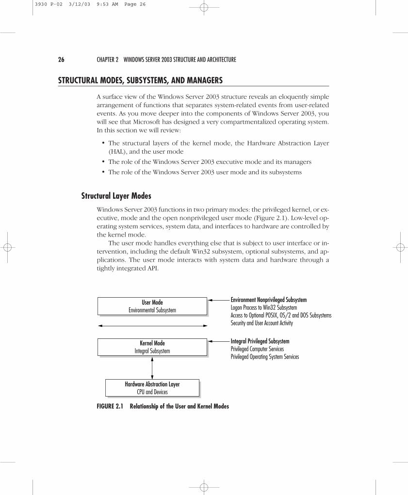
Structural Layer ModesWindows Server 2003 functions in two primary modes: the privileged kernel, or ex-ecutive, mode and the open nonprivileged user mode (Figure 2.1). Low-level op-erating system services, system data, and interfaces to hardware are controlled bythe kernel mode.
The user mode handles everything else that is subject to user interface or in-tervention, including the default Win32 subsystem, optional subsystems, and ap-plications. The user mode interacts with system data and hardware through atightly integrated API.
26 CHAPTER 2 WINDOWS SERVER 2003 STRUCTURE AND ARCHITECTURE
Environment Nonprivileged SubsystemLogon Process to Win32 SubsystemAccess to Optional POSIX, OS/2 and DOS SubsystemsSecurity and User Account Activity
Integral Privileged SubsystemPrivileged Computer ServicesPrivileged Operating System Services
User ModeEnvironmental Subsystem
Kernel ModeIntegral Subsystem
Hardware Abstraction LayerCPU and Devices
FIGURE 2.1 Relationship of the User and Kernel Modes
3930 P-02 3/12/03 9:53 AM Page 26

The Windows Server 2003 Executive ModeThe Windows Server 2003 Executive (Figure 2.2) is also known as the kernel modeand the privileged executive mode. Windows Server 2003 breaks its operationsinto five segments that run in the kernel or privileged mode:
• Hardware abstraction layer (HAL)
• Microkernel
• Device drivers
• Executive managers
• Executive services buffer
Collectively, these elements handle the system responsibilities that are hiddenfrom the user. In Windows Server 2003, the Executive controls essential operatingsystem functions. Other functions are pushed into the nonprivileged area or intoprotected subsystems, as discussed in the next section. The elements of the Exec-utive are discretely independent and exchange data through defined interfaces. Intheory, any component can be deleted and replaced with a technologically up-dated version. Assuming adherence to the interface APIs, the operating systemshould function without difficulty after swapping Executive components.
Structural Modes, Subsystems, and Managers 27
Windows Server 2003 User Mode
Windows Server 2003 Executive Kernel ModeExecutive Services
Hardware Abstraction Layer
Microkernel
I/OManager
SecurityResourceManager
IPCManager
Object Manager
Cache Manager
Devise Drivers
Configuration Manager
MemoryManager
ProcessManager
PowerManager
Plug andPlay
Manager
WindowManager
FIGURE 2.2 The Windows Server 2003 Executive Kernel Mode
3930 P-02 3/12/03 9:53 AM Page 27

Each element of the Executive provides two discrete functions. The systemservices are available in both user-mode and kernel-mode mode operations. Bycontrast, the internal routines are used only to communicate with other managersor components within the Executive itself.
THE HARDWARE ABSTRACTION LAYER
At the base of the Windows Server 2003 Executive is the Hardware AbstractionLayer. Microsoft originally placed hardware-related interfaces in a discrete segmentof code as a means of ensuring greater portability across platforms. Early WindowsNT was to be a cross-platform operating system in which HAL provided a layer ofcode that accounted for system differences. This design criterion has been elimi-nated. In Windows Server 2003, HAL deals with Intel-compatible CPU and relateddevice-dependent issues.
Concentrating on a single architecture makes the writing of device drivers con-siderably more straightforward. With a published API, application developers canwrite instructions for a device that is optimized for Windows Server 2003. Wheneverpossible, system administrators should use such enhanced device drivers.
In multiprocessor systems, HAL serves an additional function of automaticallysynchronizing hardware-related threads with the next available CPU. Prioritiesrange from real-time processes (with the highest priority) to variable, or dynamic,processes (lower priority), as discussed in a subsequent section.
THE MICROKERNEL
In operating systems such as Windows Server 2003 and UNIX, the base-level func-tions in operating system operations are managed by a kernel. In Windows Server2003 this component takes the form of a nonconfigurable and nonpageable mi-crokernel. By nonconfigurable, we mean that the microkernel is never modifiedand never recompiled; by nonpageable we mean that the 4-KB memory pages as-sociated with the microkernel are fixed and not referred to the pagefile.sys file,where dynamic paging activities are retained.
The microkernel dispatches and controls threads. (Where multiprocessors areinvolved, it also synchronizes that workload.) Dispatcher objects implement andsynchronize events, semaphores, timers, threads, and mutants (defined by mutu-ally exclusive resource access). Control objects regulate virtual address processes,system interrupts, thread profiles, and asynchronous procedure calls.
DEVICE DRIVERS
A device driver is a set of instructions that coordinates the operating system withhardware such as printers, storage units, modems, network equipment, fax ma-chines, scanners, and digital cameras. The Windows Device Model (WDM) theoret-ically allows a common set of device drivers. In theory, the WDM should greatly
28 CHAPTER 2 WINDOWS SERVER 2003 STRUCTURE AND ARCHITECTURE
3930 P-02 3/12/03 9:53 AM Page 28

reduce the system administration’s burden of maintaining multiple device driverversions. With the release of Windows Server 2003 and Windows XP, this objectivehas been largely achieved for the first time.
In the case of streaming media software, the WDM has shifted the processingfrom the user mode to WDM Kernel Streaming. The objective was to improve over-all speed and performance. An application must be specifically written for WDM totake advantage of this architecture. The same principle applies to the new WDM StillImage Architecture for specific support of digital cameras and scanners.
The space available for device drivers and system space has significantly in-creased. In Windows 2000, device drivers were limited to 220 MB; Windows Server2003 supports up to 960 MB. Windows 2000 had a total system virtual addressspace of 660 MB, compared to the 128 GB of Windows Server 2003.
EXECUTIVE MANAGERS
The fourth segment of the Executive is a collection of tightly coupled applications.Known collectively as the Executive managers, they allow the subsystems and userapplications to access system resources. Perhaps the biggest change since Windows2000 is the inclusion of a Cache Manager, which replaces memory storage in pagedpools, and the Configuration Manager, which now implements the Registry. TheExecutive managers are the following:
• The Object Manager. This manager is responsible for the creation, deletion, andinterim management of object resources: files, directories, threads, processes,ports, semaphores, events, symbolic links, and shared memory.
• The Virtual Memory Manager (VMM). The VMM regulates the allocation of32-bit or 64-bit linear memory. Windows 2003 supports virtual addressablememory—by default, half is allocated to system tasks and half to applicationworkload. (Windows 2003 Enterprise and DataCenter Editions in certain con-figurations permit the shifting of memory allocation to allow additional dedi-cated memory for application support. Applications must be coded to use theVery Large Memory (VLM) APIs.) As required, the VMM pages information todisk or physical memory. It also regulates demand paging, which uses thephysical hard drive to effectively expand total memory availability.
• The Process Manager. Windows Server support for program processes is con-trolled by threading. A thread is a logical sequence of instructions that isexecuted to completion or until a higher-priority thread temporarily preemptsit. The Process Manager specifically monitors thread and related process ob-jects. Later discussion will clarify the roles of threads and processes.
• The Interprocess Communication Manager. This Executive manager regulatesboth local procedure calls (LPCs) and remote procedure calls (RPCs). The LocalProcedure Call Facility manages client and server communications within the
Structural Modes, Subsystems, and Managers 29
3930 P-02 3/12/03 9:53 AM Page 29

computer. As a local procedure that impacts system resources is launchedfrom the user mode, the server elements in the kernel mode are called. TheRemote Procedure Call Facility manages client/server communication acrossdifferent computers.
• Security Reference Monitor (SRM). To create or gain access to an object, a re-quest must first flow through the Security Reference Monitor (Figure 2.3). Un-like some of the other Executive managers, the SRM operates in both kerneland user modes. As discussed later, each Windows Server object has a de-scriptor known as the access control list (ACL). Each user and group with ob-ject rights is provided an individual access control entry (ACE) that contains itssecurity ID (SID). Upon logging on, each user is assigned an access token thatoperates as a passkey to objects that match his or her entry levels. For greaterdetail, refer to Chapter 9, “Permissions Security, Folder Sharing, and Dfs.”
30 CHAPTER 2 WINDOWS SERVER 2003 STRUCTURE AND ARCHITECTURE
The object’s ACL is checked.
User is granted asecurity token.
User requests accessto an object.
If the user’s securitytoken matches, then
access is granted.
User logs on.
FIGURE 2.3 The Flow of Security Reference Monitoring
3930 P-02 3/12/03 9:53 AM Page 30

• I/O Manager. All input and output functions are controlled by the I/O Man-ager. These activities are broken into several components that regulate theinput and output of the system cache, file system, network drivers, and spec-ified devices (Figure 2.4).
• Windows Manager and Graphics Device Drivers. The Windows Manager andGraphics Device Drivers (GDDs) were moved from the user mode, wherethey resided in Windows NT 3.5 and earlier versions, to the kernel mode inWindows Server 2003. Applications can address the Win32K.sys interface; theGDD talks directly to HAL.
• Plug and Play Manager. The new Plug and Play Manager reduces the mun-dane system administration burden of identifying and configuring devices onthe network. It activates devices and adds devices via automatic discovery orwith the assistance of the Hardware Wizard.
• Cache Manager. This manager monitors pages faults that are required fordisk reads and data already in memory. The operating system faults data andcode into memory from disk in 4-KB page chunks and then releases before de-mand. The Cache Manager helps to prefetch pages. It also monitors the initialstages of an application startup (up to 10 seconds). The Cache Manager worksin conjunction with the Task Scheduler to signal a named event, and it callsthe Memory Manager to read data or code.
• Configuration Manager. This manager has been recoded to regulate betweenregistry settings with the executive kernel-mode subsystem. It is designed tosignificantly increase the size of Registry hive (formerly 376 MB) and therefore
Structural Modes, Subsystems, and Managers 31
CacheManager
File Manager
NetworkManager
DeviceManager
Microkernel
HardwareAbstraction
Layer
I/O Manager
FIGURE 2.4 The I/O Manager
3930 P-02 3/12/03 9:53 AM Page 31

have no hard-coded limitations. This increases performance and adds greatersupport for Terminal Server systems. The Configuration Manager also plays asecurity role, maintaining its own cache of security descriptors that may beused by multiple keys.
• Power Manager. This manager regulates the power to computers and de-vices. In systems with power management client interfaces, Windows Server2003 can automatically and remotely order a system to boot, shut down, or gointo temporary hibernation.
THE EXECUTIVE SERVICES BUFFER
The Executive Services buffer consists of a relatively small layer of code that sits ontop of the other Executive components. It separates the kernel and user modesand acts as the medium for passing API and system calls.
The Windows Server 2003 User ModeThe user mode comprises components that work together to facilitate user andapplication integrity. It has two parts:
• Protected environmental subsystems. Windows Server 2003 supports user-mode subsystems that maintain specific requirements for native Windows(16/32-bit and legacy MS-DOS), POSIX, and OS/2 applications as well as user-related system calls. An examination of protected subsystems follows.
• Dynamic integral user intervention. This part oversees the unprotected ac-tions of individual users. We discuss the impact of this dynamic interventionwhen we deal with the processes later in this chapter.
THE PROTECTED USER MODE SYSTEM
The subsystem structure can be viewed as a buffer between user applications andthe kernel-mode services structure. The term protected refers to these subsystemsbecause they are not directly changed or modified by the administrator or the userbut merely pass and manage API calls. They are configurable only through APIsand built-in utilities.
Windows Server 2003 supports two protected subsystems:
• The integral subsystem performs underlying operating system tasks—for ex-ample, security management.
• The environmental subsystem establishes the foundation for applications anduser interfaces.
32 CHAPTER 2 WINDOWS SERVER 2003 STRUCTURE AND ARCHITECTURE
3930 P-02 3/12/03 9:53 AM Page 32

Integral SubsystemsThe integral subsystems overlay and interact with the environmental subsystems.For example, the API that provides access to the network is either the WorkstationServices or the Server Services subsystem, depending on the version of WindowsServer installed. As another example, the integral Security subsystem acknowl-edges logon requests, authenticates logons, monitors the use of resources by auser, and manages user rights and permissions.
Environmental SubsystemsThe user mode supports three environmental subsystems, as shown in Figure 2.5.The intent behind this was to provide support for applications originally writtenfor other operating systems or to make porting of applications easier. Dependingon the environmental subsystem, this “support” ranges from executing shrink-wrapped applications to merely providing programming APIs. With WindowsServer 2003, this multiple environment subsystem support has been reduced.
Environmental subsystems may be thought of as operating system “multiplepersonalities.” The Win32 subsystem provides native support for applications writ-ten to support Microsoft’s 16- and 32-bit APIs. The other subsystems are a set ofAPIs that emulate other operating system calls.
• Win32 subsystem. Win32 is the mother of all subsystems. It supports standardWindows Server input and display output. Specifically, it controls the graphi-cal user interface. All Win32 applications are run directly inside this subsystem.Win32 also takes on a type of arm’s-length relationship with the other sub-systems by switching personalities when necessary.
Structural Modes, Subsystems, and Managers 33
Win32Applications
Windows Server 2003 User Mode
Windows Server 2003 Executive Kernel Mode
Win32Subsystem
16-bit Character-Based OS/2Applications
OS/2Subsystem
RecompliedPOSIX Applications
POSIXSubsystem
No Longer SupportedNo Longer Supported Integral Subsystem
FIGURE 2.5 Windows Server 2003 Subsystem Relationships
3930 P-02 3/12/03 9:53 AM Page 33
MS-DOS and 16-bit applications use both the Virtual DOS Machine (VDM)and the Win32 system. The VDM is created automatically when these programsare launched. The application process technically runs as a VDM process, butits display handling is offloaded to Win32. Because API “stubs” support the oldgraphical drivers and dynamic-link libraries (DLLs), Win16 applications gener-ally operate without affecting other operating system activities. It should beremembered that Windows Server 2003 is a preemptively multitasking operat-ing system that supports numerous single processes simultaneously. In thecase of Win16 applications, WOW, or Windows on Windows, defines the in-terplay between VDM and Win32.
• OS/2 subsystem. The OS/2 subsystem was available in Windows NT and Win-dows 2000 but is not supported on Windows Server 2003.
• POSIX subsystem. The Portable Operating System Interface computing envi-ronment subsystem was available in Windows NT and Windows 2000 but is notsupported on Windows Server 2003.
For those interested in POSIX and UNIX interoperability, Microsoft has madeavailable its Services for UNIX 3.0. This offers an assortment of third-party UNIXapplications and utilities, including Korn and C shell support and NFS. By addingthese features, it is possible to use many scripts written in a UNIX environmentand move them directly across to Windows Server 2003. This is to be offered aspart of an optional service package known as Microsoft Services for UNIX. The In-terix code actually replaces Microsoft’s POSIX subsystem and overlays a completeUNIX 95 environment within Windows. In this configuration, true operating sys-tem interoperability is achieved. It is also possible to migrate existing UNIX appli-cations to Windows Server 2003 with comparative ease. Among the common UNIXfeatures that Interix provides are the following:
• More than 300 UNIX commands and utilities
• Shell support for the Korn shell, Bourne shell, and C shell
• Scripting languages—awk, Perl, sed, Tcl/Tk—with full shell job control
• POSIX.1, POSIX.2, and ANSI C interfaces
• BSD sockets implemented with Winsock
• SVID IPC (message queues, semaphores)
• Shared memory, memory-mapped files
• ODBC and OpenGL application library support
• X11R5 Windowing System clients and libraries
• The X11R6.3 Windowing System display server
34 CHAPTER 2 WINDOWS SERVER 2003 STRUCTURE AND ARCHITECTURE
3930 P-02 3/12/03 9:53 AM Page 34

• X11R6 fonts and font management
• The OSF/Motif® 1.2.4 Window Manager and libraries
• Execution of Win32 applications from Microsoft Services for UNIX
• Full tty semantics mapped to console windows and pseudoterminal support
• Full integration with the Windows NT security model, administration, file sys-tems, networking, and printers
• Telnetd and rlogind services (multiuser logon support)
• Berkeley r-utilities (servers and clients)
MKS and its DataFocus division’s NutCRACKER development product alsoprovide POSIX utilities and application porting directly to the Win32 API.
WINDOWS SERVER 2003 PROCESSES
Windows Server 2003 processes are viewable through a surprisingly simple yet in-formative set of graphical utilities. Using the Task Manager (with three equallyhelpful screens), the Event Viewer, the Services Manager, and the Resource-Kit-based Process Viewer, a system administrator can review and govern many of theprocess-oriented activities of the local server. The Task Manager can also rapidlyaddress many performance issues. These tools effectively manage a robust process-oriented, multitasking, and multithreading operating system.
After reviewing this section, a system administrator should have sufficientbaseline information to do the following:
• Understand Windows Server 2003 processes, threads, pipes, and handles.
• Use the Task Manager and Services Manager to identify, start, and killprocesses.
• Use the Event Viewer to diagnose process success and failure.
• Employ the Process Viewer to ascertain priorities.
• Schedule processes.
Processes, Threads, and HandlesA Windows Server 2003 process is an executable that flows through a logical se-quence of events until the appointed action is complete. Technically, an exe-cutable program is composed of the base code and related data, a dedicatedmemory address space, defined system resources, and at least one thread. Athread is the portion of the process being executed. It has a unique identification,its client ID, and a register that defines its microprocessor state. Every thread
Windows Server 2003 Processes 35
3930 P-02 3/12/03 9:53 AM Page 35

maintains reserved memory stacks for the execution in the user and kernel modes.It also has storage memory for interaction with other applications, DLLs, run-timelibraries, and environmental subsystems.
Processes use threads to invoke an action with a reaction, pipes to connectthreads, and semaphores to synchronize activities. Unlike UNIX processes, whichinvolve exec/fork replication and parent/child relationships, Windows Server 2003utilizes handles. Handles are assigned to threads and identify resources such as aRegistry key used for access by a program. (Handles are also applied to events, sem-aphores, pipes, processes, and communications.)
A Windows Server 2003 process is treated as an object. As such it has a num-ber of characteristics, including a virtual memory address, defined resources, anda security profile. Each process has one or more thread objects associated with itsexecution. As an object, the thread also has a unique memory stack and systemstate. The thread is an agent that does the bidding of the process. The Object Man-ager controls both process and thread objects.
When a new process is created, the CreateProcess() and CreateThread() callsare made. As additional threads are required to support a given process, other Cre-ateThread() calls are invoked. The thread should be thought of as a unit of exe-cution. Between the ends of the thread is a pipe, both ends of which must be open.If either end is broken, the process data is lost.
Windows Server 2003 also uses named pipes to transmit information. Thesepipes are viewed similarly to file objects and operate within the same securityframework. A named pipe retains information in memory and dispenses the dataas requested by a process. It acts like a regular data file, except that the informa-tion is in resident memory, not physically archived on disk. Figure 2.6 illustratesthe hierarchy of processes.
Windows Server 2003 is a multitasking and multithreaded operating system.One of its strengths is its ability to manage and synchronize multiple threads. Ona single-processor system, only one thread can execute at a time, but, as a resultof context switching, it appears to the user that multiple threads are running. Inthis scheme (Figure 2.7), a thread executes until it has completed its task, is in-
36 CHAPTER 2 WINDOWS SERVER 2003 STRUCTURE AND ARCHITECTURE
Kernel Executive Managers
Process Thread Handles
Object Manager Security Manager I/O Manager
FIGURE 2.6 Process Hierarchy
3930 P-02 3/12/03 9:53 AM Page 36

terrupted by a thread with a higher priority, or waits for system resources. Duringan interruption, the Windows Server saves the “context” of the thread and reloadsit when the CPU is free to continue.
Windows Server 2003 provides a robust process and thread priority facility.The programming API permits the setting of application process priorities, orstates, that include idle, normal, high, and real-time; within each of these statestwo subpriorities can be established. It is important for a programmer to considerthe impact of this facility on the entire system. There are 32 priority levels numbered0 through 31. The first 16 (0–15) are reserved for the user mode, and the remain-der are reserved for the kernel mode. After a base priority level is set for a processor a thread, the kernel may dynamically raise it in the event of user interaction. Bythe same token, the kernel can lower the priority rating for strictly computer-as-sociated operations.
How long a thread is allowed to execute is controlled by a property known asa quantum. A quantum type can be of fixed or variable length. By default, WindowsServer 2003 versions give priority to fixed-quanta background services, althoughWindows XP gives higher priority to applications that generally use variable-lengthquanta. In theory, these priorities provide greater smoothness to key multitaskingfunctions of the respective environments.
MULTIPROCESSOR SUPPORT
Where processing load is significant, systems with more than one CPU can reducethread executing wait times. Windows Server 2003 uses symmetric multiprocessing(SMP), which allows user and kernel-mode activities to use any available processor.
Windows Server 2003 Processes 37
Higher-priority thread begins/Ends
Higher-priority thread begins/Ends
Thread shifts and continues
Thread finishes processThread begins/Gets interrupted
Thread begins/Gets interrupted
Thread Process in a Preemptive Multitasking Environment
Multithreaded Process in a Multiprocessor Environment
FIGURE 2.7 Single and Multiprocessor Preemptive Multitasking
3930 P-02 3/12/03 9:54 AM Page 37
Symmetric multiprocessor systems have identical processors and functions. (Bycontrast, an asymmetric multiprocessor system allocates resources to a specificprocessor even if that CPU is overloaded and others are relatively free.) The clearadvantage is the balancing of the processing load across all resources.
Process Accounting and CPU ThrottlingWith its Internet Information Services, Windows Server 2003 adds two featuresthat make multiuser environments more efficient. The first is processor account-ing, which measures the number of processor cycles consumed by Web requests.The second is CPU throttling, which restricts Web applications from overwhelm-ing CPU time. Both are enabled by job objects, which allow the operating systemto manage groups of processes as a single unit. The use and administration ofprocess accounting and CPU throttling are discussed in Chapter 16.
Interprocess CommunicationInterprocess communication (IPC) and remote procedure call (RPC) are basic toWindows Server 2003. (At the risk of being overly simplistic, RPC can be regardedas the distributed network version of IPC.) Microsoft claims that its implementationof RPC is compliant with Distributing Computing Environment (DCE).
Windows Server 2003 employs a direct relationship between processes andthreads. At any given time, there is a producer and a consumer (similar to BSDsocket library calls in UNIX). The objective is to achieve a very scalable operating sys-tem that permits easy load balancing of discrete measured threads. WindowsServers also employs a FIFO (first-in, first-out) message model.
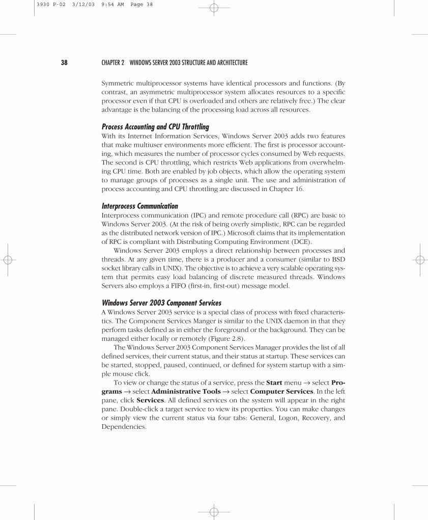
Windows Server 2003 Component ServicesA Windows Server 2003 service is a special class of process with fixed characteris-tics. The Component Services Manger is similar to the UNIX daemon in that theyperform tasks defined as in either the foreground or the background. They can bemanaged either locally or remotely (Figure 2.8).
The Windows Server 2003 Component Services Manager provides the list of alldefined services, their current status, and their status at startup. These services canbe started, stopped, paused, continued, or defined for system startup with a sim-ple mouse click.
To view or change the status of a service, press the Start menu → select Pro-
grams → select Administrative Tools → select Computer Services. In the leftpane, click Services. All defined services on the system will appear in the rightpane. Double-click a target service to view its properties. You can make changesor simply view the current status via four tabs: General, Logon, Recovery, andDependencies.
38 CHAPTER 2 WINDOWS SERVER 2003 STRUCTURE AND ARCHITECTURE
3930 P-02 3/12/03 9:54 AM Page 38
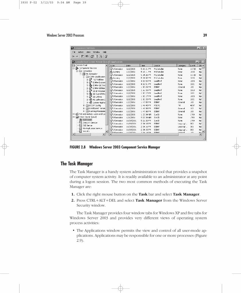
The Task ManagerThe Task Manager is a handy system administration tool that provides a snapshotof computer system activity. It is readily available to an administrator at any pointduring a logon session. The two most common methods of executing the TaskManager are:
1. Click the right mouse button on the Task bar and select Task Manager.
2. Press CTRL+ALT+DEL and select Task Manager from the Windows ServerSecurity window.
The Task Manager provides four window tabs for Windows XP and five tabs forWindows Server 2003 and provides very different views of operating systemprocess activities:
• The Applications window permits the view and control of all user-mode ap-plications. Applications may be responsible for one or more processes (Figure2.9).
Windows Server 2003 Processes 39
FIGURE 2.8 Windows Server 2003 Component Service Manager
3930 P-02 3/12/03 9:54 AM Page 39

• The Processes window provides in-depth information about individualprocesses, including resource utilization.
• The Performance window provides a graphical and numeric view of the sys-tem based on the current application and process load.
• The Networking tab identifies the amount of current network activity on thecomputer.
• The Users tab (Windows Server 2003 only) identifies local users and remoteusers by name, ID, activity status, and client system name.
A simple dissection of the Applications window shows the application name inthe first column followed by the current status. The bottom set of buttons permitsthe administrator to End Task, Switch to another task, or invoke a New Task.
At the bottom of the screen is a system summary status that includes a number ofopen processes, CPU usage, and memory utilization.
40 CHAPTER 2 WINDOWS SERVER 2003 STRUCTURE AND ARCHITECTURE
FIGURE 2.9 The Task Manager Applications Window
3930 P-02 3/12/03 9:54 AM Page 40
STARTING AND KILLING PROCESSES
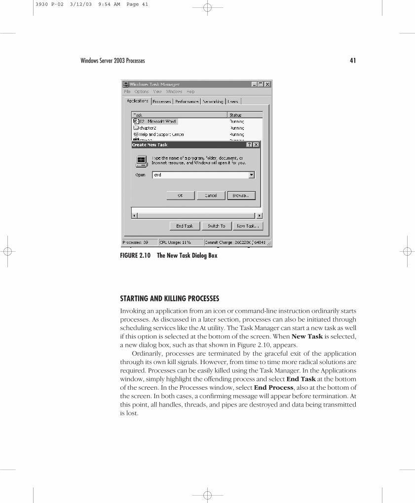
Invoking an application from an icon or command-line instruction ordinarily startsprocesses. As discussed in a later section, processes can also be initiated throughscheduling services like the At utility. The Task Manager can start a new task as wellif this option is selected at the bottom of the screen. When New Task is selected,a new dialog box, such as that shown in Figure 2.10, appears.
Ordinarily, processes are terminated by the graceful exit of the applicationthrough its own kill signals. However, from time to time more radical solutions arerequired. Processes can be easily killed using the Task Manager. In the Applicationswindow, simply highlight the offending process and select End Task at the bottomof the screen. In the Processes window, select End Process, also at the bottom ofthe screen. In both cases, a confirming message will appear before termination. Atthis point, all handles, threads, and pipes are destroyed and data being transmittedis lost.
Windows Server 2003 Processes 41
FIGURE 2.10 The New Task Dialog Box
3930 P-02 3/12/03 9:54 AM Page 41

Figure 2.11 provides a real-time view of network utilization on the local clientor server system.
NOTE Administrators coming from the UNIX environment occasionally face a runawayprocess known as a zombie. Microsoft claims that zombies will not occur in WindowsServer 2003 because its processes do not use the parent/child relationship inherentin UNIX. Each Windows Server process is discrete and independent of the presenceor health of a parent. While this may be technically true, certainly some processes(generated by either Microsoft or third-party software) begin sapping very largeamounts of memory and become very difficult to kill. Use the Task Manager or theProcess Viewer to kill such processes. On rare occasions, you may have to invoke theaction more than once.
42 CHAPTER 2 WINDOWS SERVER 2003 STRUCTURE AND ARCHITECTURE
FIGURE 2.11 Task Manager Local Area Connection Monitor
3930 P-02 3/12/03 9:54 AM Page 42
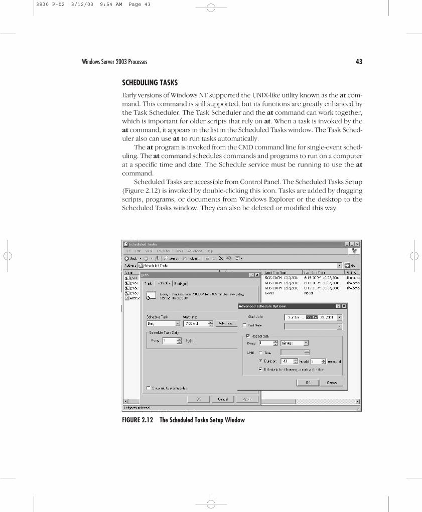
SCHEDULING TASKS
Early versions of Windows NT supported the UNIX-like utility known as the at com-mand. This command is still supported, but its functions are greatly enhanced bythe Task Scheduler. The Task Scheduler and the at command can work together,which is important for older scripts that rely on at. When a task is invoked by theat command, it appears in the list in the Scheduled Tasks window. The Task Sched-uler also can use at to run tasks automatically.
The at program is invoked from the CMD command line for single-event sched-uling. The at command schedules commands and programs to run on a computerat a specific time and date. The Schedule service must be running to use the at
command.Scheduled Tasks are accessible from Control Panel. The Scheduled Tasks Setup
(Figure 2.12) is invoked by double-clicking this icon. Tasks are added by draggingscripts, programs, or documents from Windows Explorer or the desktop to theScheduled Tasks window. They can also be deleted or modified this way.
Windows Server 2003 Processes 43
FIGURE 2.12 The Scheduled Tasks Setup Window
3930 P-02 3/12/03 9:54 AM Page 43

VIEWING PROCESSES
The Processes window provides system administrators with a very good snapshotof their system’s activity. Its default screen has five process checkpoints: ImageName, User Name, Session ID, CPU, and MEM Usage (Figure 2.13). A total of 22items may be selected for analysis by changing Select Columns in the View menu.When the dialog box appears, use the mouse to click the additional reporting pa-rameters. If all options are selected, the system administrator has a reasonably com-prehensive view of active processes and their impact on the overall system, asshown in Figure 2.14.
The Task Manager Performance screen (Figure 2.15) displays four graphical rep-resentations and four boxes of numeric data for the entire system:
• CPU Usage shows current CPU utilization (in this example, the CPU has reacheda critical utilization state).
• CPU Usage History is a longer-term view generally showing CPU usage overtime. Unfortunately, in this window there is no ability to change time intervalsor to save or print this information. A tool to refine this view can be accessedby pressing Start → Programs → Administrative Tools → Performance.
44 CHAPTER 2 WINDOWS SERVER 2003 STRUCTURE AND ARCHITECTURE
FIGURE 2.13 The Task Manager Process List
3930 P-02 3/12/03 9:54 AM Page 44

Windows Server 2003 Processes 45
FIGURE 2.14 Expanded View of Process Activities
FIGURE 2.15 The Task Manager Performance Window
3930 P-02 3/12/03 9:54 AM Page 45
• PF Usage shows utilization based on pagefiles.
• PF History shows fluctuation of pagefile usage over time. You can refine thisview by pressing Start → Programs → Administrative Tools →Performance.
• Totals shows the number of open handles, threads, and processes.
• Physical Memory summarizes the system memory defined as a total, currentlyavailable, and cache available in kilobytes.
• Commit Charge shows the total memory allocated to programs, the systemlimit, and peak memory, including swap memory.
• Kernel Memory defines the total memory allocated to kernel-mode activities,broken down by paged and nonpaged events.
New performance tools available with Windows Server 2003 include:
• Disk input and output (I/O)
• Memory management (e.g., working set management, page fault)
• Image load and unload
• Process and thread activities such as process create, thread create, and contextswitching
• Registry
• Driver delays
• Pool allocations
• Heap allocations
• Central profiling that examines both kernel-mode and user-mode activities
Monitoring processor activity is effectively accomplished by looking at theProcess and System object counters. In addition to providing information on uti-lization, it can pinpoint bottlenecks. The specific items you should examine are:
• Processor\% Processor Time for processor usage
• Optionally, you can also monitor Processor\% User Time and % PrivilegedTime along with % Processor Time for more detail
• System\Processor Queue Length for bottleneck detection
The Processor\% Processor Time counter is used to gauge the activity of theprocessor. Look specifically at the counter showing the percentage of elapsedtime that a processor is busy executing a non-idle thread.
An examination of processor usage is not straightforward. For example, highprocessor values could indicate either the efficient handling of a heavy work-load or a struggle to keep up. Typically, you will need to understand which appli-
46 CHAPTER 2 WINDOWS SERVER 2003 STRUCTURE AND ARCHITECTURE
3930 P-02 3/12/03 9:54 AM Page 46
cations cause peak processor loads such as software that involves heavy computa-tions. When these applications are churning, anticipate peak loads. If this becomesa problem that impacts other applications, then workload scheduling is appropri-ate. By contrast, if the processor is peaking because many clients are using the sys-tem, then consider adding system resources or offloading some users to anothersystem.
A processor bottleneck simply occurs when too many threads place demandson the processor. A processor queue develops as the threads back up. CPU-boundapplications and driver components are notorious for creating bottlenecks. TheSystem\Processor Queue Length counter is used to determine the existence ofbottlenecks. A queue of two or more items indicates a bottleneck over time (asnapshot of a number higher than 4 should also be considered a critical bottlenecknumber.) When this occurs, you have only a couple of options. From a hardwareperspective, you can get a faster processor or add a processor. Alternatively, youcan restrict application and user activity.
Interrupt activities can also cause a bottleneck. The Processor\Interrupts/seccounter measures the rate of service requests from I/O devices. An increase of thecounter value without a corresponding jump in system activity suggests a hard-ware problem. The Processor\% Interrupt Time is also a modestly good indicatorof the interrupt activity of disk drivers, network adapters, and other devices.
NOTE Windows Server 2003 has new Performance security groups. Members of the Per-formance Monitor Users group can monitor performance counters on the server lo-cally and from remote clients. Members of the Performance Log Users group canmanage performance counters, logs, and alerts on the server locally and from re-mote clients. These features permit the delegation of responsibilities withoutgranting full administrative rights.
Performance Monitoring of Multiple ServersWindows Server 2003 allows administrators to collect performance counter datafor a group of servers. All performance objects, counters, and instances can beutilized.
The select multiple objects in Performance Monitor (PerfMon) permit visualiza-tion and analysis of performance data. Specifically, this feature supports log mon-itoring and alerts services. To invoke this feature: Start → Control Panel →Performance and Maintenance → Administrative Tools → Performance
→ System Monitor.It is important to note that this feature is not available in SysMon for real-time
monitors because there is too much data.
Windows Server 2003 Processes 47
3930 P-02 3/12/03 9:54 AM Page 47

Command-Line OptionsWindows Server 2003 adds performance control command-line tools. They includefunctions that provide management of the control performance counter, eventtrace log scheduling, and collection and analysis on local and remote computers.These functions are accomplished without the need for the System Monitor (Sys-mon) UI. The new tools and the functions they allow managers to perform are:
• Logman—Start, stop, query, and schedule performance data and event tracelog collection.
• Relog—Given specified intervals, sample performance counter logs to extractspecific counters and write to a new log file in a different format.
• Tracerpt—Report and analyze process kernel, Active Directory, and othertransaction-based trace event logs.
• Typeperf—Write performance data to the command line every “n” samples.
These command-line tools are available by typing the command in the com-mand prompt window.
THE EVENT VIEWER
The Event Viewer provides a defined log for both normal and abnormal systemevents. It can be one of the most valuable system administrative tools for trou-bleshooting problems. A regular analysis of these logs should be undertaken if sys-tem problems are suspected.
In Windows an event is any system occurrence that requires notification. Onetype of event recorded in the Event Viewer system log is a dysfunctional driver orload failure (Figure 2.16). The Source column identifies the application that initi-ated the message. The Category classifies the event as being related to security,object access, logon/logoff, detail tracking, system, policy changes, account man-agement, and miscellaneous (none).
The level of importance of an event message is shown as an icon in the ex-treme left column: Error, Informational, Warning, Success Audit, and Failure Audit.This application can be launched from the Event Viewer for the local system byclicking the Start menu → selecting Run → typing eventvwr → clicking Enter.Alternatively, the Event Viewer is available from Administrative Tools.
The Event Viewer has a very flexible set of options that permits long-term track-ing of system, security, and application problems. These options are described inTable 2.1.
48 CHAPTER 2 WINDOWS SERVER 2003 STRUCTURE AND ARCHITECTURE
3930 P-02 3/12/03 9:54 AM Page 48

Windows Server 2003 Processes 49
FIGURE 2.16 The Event Viewer Screen
TABLE 2.1 Event Viewer Options
Option Description
Logging Rolls events as needed; removes events after a defined number of days;prohibits overwriting of events (requires manual event removal).
Sorting Sorts events based on categories, sources, user, or machine.
Archiving Saves event records in native Event format (*.EVT) or in normal or comma-delimited ASCII text (*.TXT) format.
Details Provides additional information on the event.
Filtering Filters desired events or characteristics.
Find Locates events based on type, category, source, computer, or other criteria.
To review details, highlight the item in the right detail panel and double-click.The appropriate event properties window will then be displayed for analysis andaction. As seen in Figure 2.17, a significant amount of information is provided to
3930 P-02 3/12/03 9:54 AM Page 49

permit zeroing in on the precise location of the event. If a warning or error occurs,appropriate action can then be taken.
NOTE In Windows 2000, the Event Viewer feature was introduced that allowed Event Logerror messages to manually add hyperlinks to Web sites by changing .RC and .MCfiles. Windows Server 2003 automatically adds a standard phrase and a Uniform Re-source Locator (URL) to each message with the message properties dialog initial-ization. In addition, an optional string value can be added to the registry to specifythe target URL.
NOTE System logs are essential to system performance analysis. Windows Server 2003provides the generation of Perf Logs to the size of 1 GB. With a new file format,these logs can be appended to an existing log file.
50 CHAPTER 2 WINDOWS SERVER 2003 STRUCTURE AND ARCHITECTURE
FIGURE 2.17 Event Log Properties
3930 P-02 3/12/03 9:54 AM Page 50

STORED AND VIRTUAL MEMORY
Stored memory is the storage of data bits on devices such as a hard drive. Its man-agement is predicated on the type of file system being used. The role and dynam-ics of storage for Windows Servers vary radically among the native NT File System(NTFS), the file allocation table (FAT), and FAT32. In general, stored memory isdesignated as “storable” and “retrievable archival.” All three file system types aresupported on x86 computer systems.
Virtual memory is defined as dynamic or temporary. Physical memory,
known as random access memory (RAM), combines with temporary disk storage.For example, if a process requires more memory than is available from the sys-tem’s RAM, the hard drive is used to temporarily store process data. It uses a setof temporary registers where information about processes is stored during execu-tion. This is known as paging.
Stored Memory and File System BasicsWindows Server 2003 supports three file systems, NTFS, FAT, and FAT32, each ofwhich has unique characteristics. For base-level security we have already estab-lished the clear advantage of native NTFS. However, under some circumstances,such as a need to switch between older Windows versions and Windows Server2003, the FAT file system is necessary. FAT32 is an expanded version of FAT thatallows larger disk partitions and is used primarily in the Windows 98 operating sys-tem. The relative merits of the three file systems are examined in detail in Chapter14, but a brief review is appropriate at this stage.
THE FILE ALLOCATION TABLE: FAT AND FAT32
For the sake of this discussion, FAT and FAT32 are viewed as the same system ex-cept where specifically noted.
A file allocation table, FAT, is a simple file system that dates back to the dayswhen the 5 1⁄4-inch floppy drive was the default medium and a 10-MB hard drivewas an expensive luxury. In many cases, a system administrator may install Win-dows Server 2003 using FAT because of legacy MS-DOS or Windows 3.x applica-tions that simply have not been updated to take advantage of Win32 functionality.FAT32, introduced to support Windows 98, is simply an extension of FAT with ad-ditional 32-bit application support.
A number of limitations, such as reduced security, are inherent in FAT andFAT32. Even so, these file systems are acceptable for legacy environments. Onevery nice feature Microsoft has included is the ability to convert the file systemfrom FAT to NTFS (but not vice versa) when appropriate. This is accomplished by
Stored and Virtual Memory 51
3930 P-02 3/12/03 9:54 AM Page 51

invoking the convert command from the Virtual DOS Machine with the followingsyntax:
CONVERT [drive:] /fs:ntfs [/nametable:filename]Where filename is the name of file that is created during theconversion process that contains a name translation table for unusualfilenames.
The file allocation table includes the following basic information about a file:
• The name of the file or directory (folder) with a structured maximum 8-character name and a 3-character mandatory extension, known as the 8.3 format
• A pointer to the physical location of the first byte of data associated with thefile
• The size of the file in bytes
• The designation of the file’s attributes as hidden, read-only, archive, or system-based
In the context of file storage on a disk or partition, the FAT hierarchy is very sim-ple (Figure 2.18). The first sector contains the machine BIOS block followed by thefile allocation table and a duplicate image. The root directory is the first set of in-formation visible to a user. Individual files are stored in the root directory or in cre-ated subdirectories.
THE NTFS FILE SYSTEM
NTFS was introduced with Windows NT 3.1 as an outgrowth of the original OS/2High-Performance File System (HPFS). With the introduction of Windows NTServer 4.0, the NTFS file system has taken a giant leap forward in terms of stability
52 CHAPTER 2 WINDOWS SERVER 2003 STRUCTURE AND ARCHITECTURE
Stored Files/Objects
BIOS Block
Duplication FAT
File Allocation System
FIGURE 2.18 Disk Structure of the FAT File System
3930 P-02 3/12/03 9:54 AM Page 52
and flexibility. It boasts numerous advantages over the FAT file system, includingthe following:
• Superior security extends to files, processes, and user access protection.
• Fault tolerance uses a redundant array of inexpensive disks (RAID 1-5) to cre-ate duplicates of all files on servers. If a bad partition is detected, for example,Windows Server 2003 can use these copies to create a new sector.
• Unicode supports file names, dedicating 16 bits per character with a maximumof 255 characters. This facilitates internationalization. FAT supports only 8characters using 7- or 8-bit ASCII and ANSI standards.
• Master File Table redundancy ensures recovery of system data in the case ofcorruption.
• 32-bit virtual memory support has 2 GB allocated to system requirements and2 GB to applications.
• File name length is 255 characters but also automatically generates the shorterDOS files names for backward compatibility.
NOTE Windows Server 2003 tightens the security of NTFS by providing only the admin-istrator the right to write to the root directory. In previous versions, Everyone hasfull control in the root directory. The tightened security also prevents anyoneother than administrators from modifying files in the root directory that were cre-ated by other users.
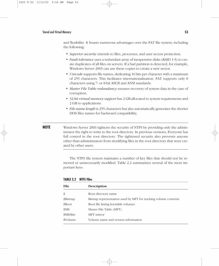
The NTFS file system maintains a number of key files that should not be re-moved or unnecessarily modified. Table 2.2 summarizes several of the most im-portant keys.
Stored and Virtual Memory 53
TABLE 2.2 NTFS Files
File Description
$ Root directory name
$Bitmap Bitmap representation used by MFT for tracking volume contents
$Boot Boot file listing bootable volumes
$Mft Master File Table (MFT)
$MftMirr MFT mirror
$Volume Volume name and version information
3930 P-02 3/12/03 9:54 AM Page 53
NTFS Version 5 DifferencesThe Windows Server 2003 implementation of NTFS is version 5, which differs in anumber of ways from the NTFS used in Windows NT for versions before ServicePackage 4. It is not backward compatible. Rather, during installation, if NTFS 4.0 isdetected on a disk, it is upgraded to version 5.
One of the principal differences between NTFS version 5 and earlier versionsis that NTFS 5 can undertake something akin to symbolic linking through the useof reparse points. The reparse point is 16 KB of data that takes the form of a tag thatidentifies the device driver. When a Windows Server 2003 NTFS process sees areparse point tag, it redirects the action to the defined device driver. A symbolic
link is a special type of reparse point used to redirect the NTFS process to a spec-ified file or directory.
NTFS 5 has a useful link-tracking facility. Anytime a linked item is moved any-where within the same domain, the link is tracked and remains intact.
NTFS 5 also supports disk quotas. These quotas are important because they per-mit regulation of disk usage. The specific management of disk quotas is discussedin Chapter 14.
Another important enhancement with NTFS 5 is support for the EncryptingFile System (EFS). When a user wants to encrypt a file, a file encryption key (FEK) isgenerated. The Windows Server 2003 EFS uses an extended variant of the Data En-cryption Standard algorithm (DESX).
NTFS 5 expands support of the CD-ROM File System (CDFS) that was basedon a read-only principle. It now supports the Universal Data Format (UDF), whichis emerging as the DVD-ROM format.
Finally, NTFS 5 supports FAT32 drives. Windows NT should not interpret FAT32partitions or drives, nor can it boot from a FAT32 partition. Windows Server 2003NTFS overcomes both of these limitations.
FILE OBJECTS IN THE NTFS FILE SYSTEM
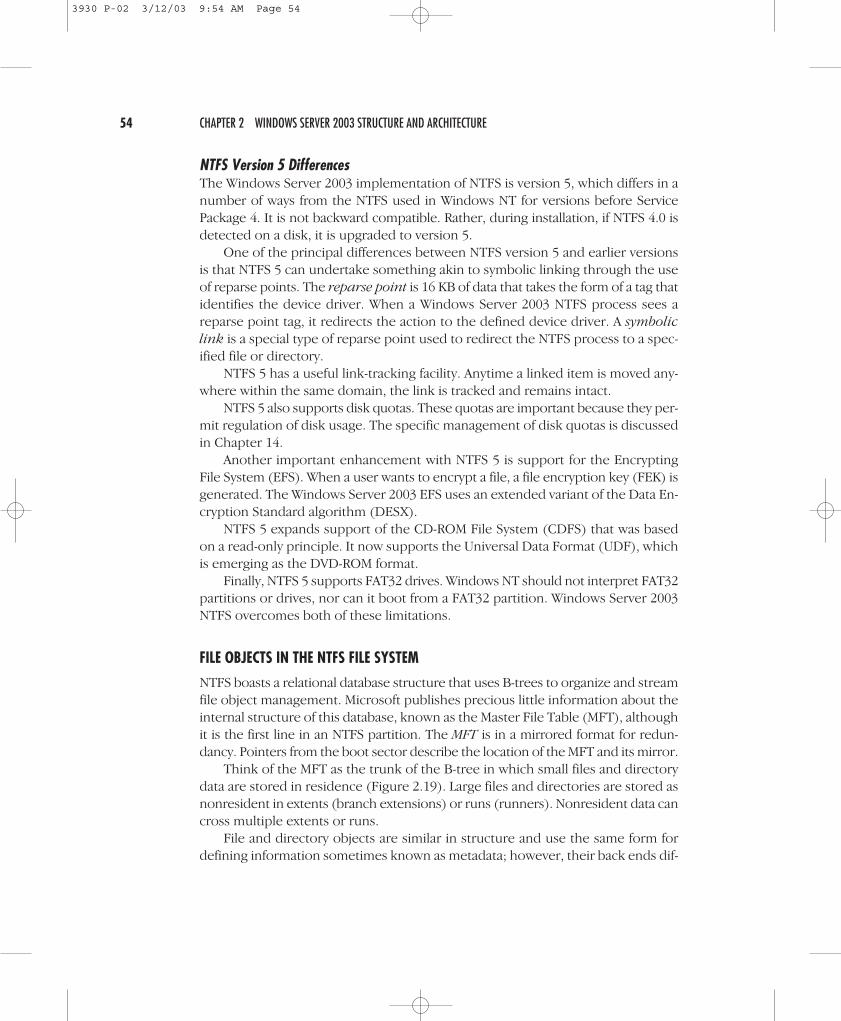
NTFS boasts a relational database structure that uses B-trees to organize and streamfile object management. Microsoft publishes precious little information about theinternal structure of this database, known as the Master File Table (MFT), althoughit is the first line in an NTFS partition. The MFT is in a mirrored format for redun-dancy. Pointers from the boot sector describe the location of the MFT and its mirror.
Think of the MFT as the trunk of the B-tree in which small files and directorydata are stored in residence (Figure 2.19). Large files and directories are stored asnonresident in extents (branch extensions) or runs (runners). Nonresident data cancross multiple extents or runs.
File and directory objects are similar in structure and use the same form fordefining information sometimes known as metadata; however, their back ends dif-
54 CHAPTER 2 WINDOWS SERVER 2003 STRUCTURE AND ARCHITECTURE
3930 P-02 3/12/03 9:54 AM Page 54
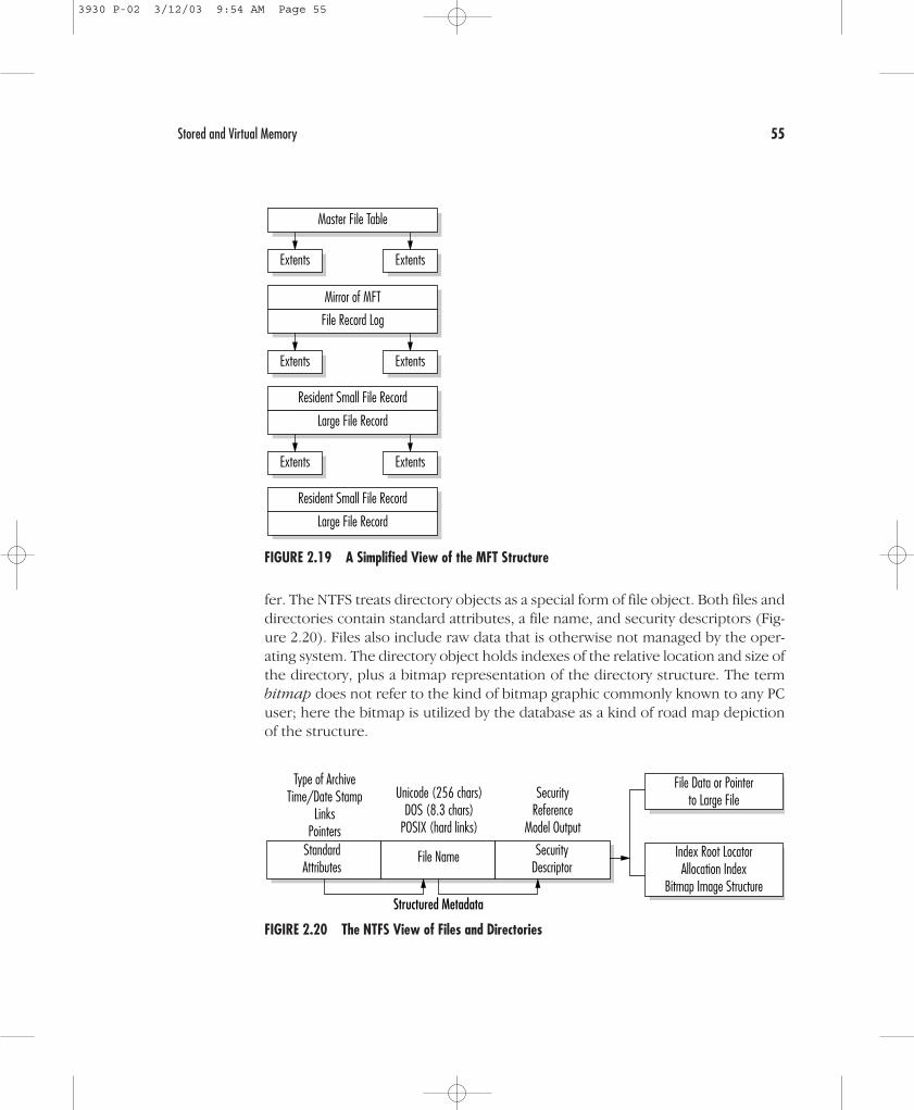
fer. The NTFS treats directory objects as a special form of file object. Both files anddirectories contain standard attributes, a file name, and security descriptors (Fig-ure 2.20). Files also include raw data that is otherwise not managed by the oper-ating system. The directory object holds indexes of the relative location and size ofthe directory, plus a bitmap representation of the directory structure. The termbitmap does not refer to the kind of bitmap graphic commonly known to any PCuser; here the bitmap is utilized by the database as a kind of road map depictionof the structure.
Stored and Virtual Memory 55
Master File Table
Mirror of MFT
Resident Small File Record
Large File Record
Resident Small File Record
Large File Record
File Record Log
Extents Extents
Extents Extents
Extents Extents
FIGURE 2.19 A Simplified View of the MFT Structure
File NameStandardAttributes
SecurityDescriptor
Unicode (256 chars)DOS (8.3 chars)
POSIX (hard links)
SecurityReference
Model Output
Type of ArchiveTime/Date Stamp
LinksPointers
File Data or Pointerto Large File
Index Root LocatorAllocation Index
Bitmap Image StructureStructured Metadata
FIGIRE 2.20 The NTFS View of Files and Directories
3930 P-02 3/12/03 9:54 AM Page 55

File names follow a specific convention depending on the file system; FAT hasan 8-character maximum with a 3-character extension (8.3) and NTFS has a maxi-mum of 255 characters. Directories are separated in all cases with the backslash (\).Windows NT directories are similar to UNIX directories in that they are a specialform of file object that merely maintains information about the files they manage.
The NTFS database structure facilitates system recovery, which is not avail-able with the file allocation table. NTFS’s transaction database methodologyemploys a logging process to initiate disk-writing instructions. Data enterscache memory, where it is then directed to the VMM for background or lazywriting to disk. The VMM sends the data to the fault-tolerant driver (assumingthe existence of a RAID structure), which then attempts to physically write tothe drive. If it is successful, the transaction in the database is released. If notsuccessful, the record of the logged process is retained in the transaction tableuntil restoration.
The Virtual Memory Manager and PagingWindows Server 2003 uses a flat 32-bit virtual and linear memory scheme, reserv-ing half of the capacity for system resources and half for applications. It allows tun-ing of addressable memory for applications, which was unavailable to WindowsNT. For information on how this is accomplished for your version of the operatingsystem, examine the Help files. The VMM allocates each process an address space,which is then mapped to physical memory in 4-KB pages (Figure 2.21). As mem-ory is required, the system swaps between physical memory (hardware RAM) andpageable memory stored on the hard drive.
The VMM provides memory mapping through a table that defines virtual ad-dresses. It also regulates the paging process—the movement from physical to diskmemory. The area on a disk drive where paging occurs is known as the pagefile,the proper sizing of which can be critical to overall system performance. By de-fault, Windows Server 2003 sets up a pagefile equal to the amount of installed RAMplus 12 MB (unless the available disk space is less than that formula). The mini-
56 CHAPTER 2 WINDOWS SERVER 2003 STRUCTURE AND ARCHITECTURE
First in/First out
VirtualAddress
PhysicalMemory
PagesPagefile
Windows2000Virtual
MemoryManager
FIGURE 2.21 Virtual Memory and Paging
3930 P-02 3/12/03 9:54 AM Page 56

mum pagefile size is 2 MB. Since hard drive space is relatively inexpensive, we rec-ommend expanding the pagefile if system performance becomes an issue.
Pagefile size is changed in the following steps after you log on as the adminis-trator: Open Control Panel → double-click the System icon → select Advanced
System Properties → click Performance → click Change → if multiple drivesare listed in the Drive box, select the drive containing the pagefile → in the Initial
Size box, increase or decrease the amount → click Set → click OK to close theVirtual Memory box → click OK on the Performance Options box → click OK
on the Systems Property box. The computer must be restarted for the change totake effect.
THE BOOT PROCESS
The Windows Server 2003 booting sequence involves a series of system configu-ration checks, hardware activation, and application loading. The following lists theboot process:
• Power on self-test (POST) checks whether key hardware elements are present,such as sufficient memory, keyboard, video card, and so forth.
• Startup initialization checks the hard drive’s first sector for the Master BootRecord (MBR) and partition table. If either is missing or corrupted, the processterminates.
• Memory switch and system driver load. An operating system load driver,Ntldr, instructs the microprocessor to convert from real mode to protectedmemory mode used by Windows Server 2003. Appropriate system drivers arethen started that are actually built into Ntldr and that identify the type(s) of filesystem(s) present.
• The boot loader permits the selection of the desired environment wherethere are multiple operating systems on the system. The system looks forNtldr in the root directory (by reading Boot.ini and invoking Ntdetect.com andBootsect.dos). A typical boot loader screen (for a dual-boot environment) isshown here. (A single boot screen would show only Windows Server.)
Please select the operating system to start:Windows Server 2003 (or Standard, Enterprise, DataCenter, Web)Windows 2000
Use ≠ and Ø to move the highlight to your choice.Click Enter to choose.Seconds until highlighted choice will be started automatically is: 23
Boot.ini is divided into two sections: boot loader and operating systems. Theboot loader defines the number of seconds before an automatic load of the default
The Boot Process 57
3930 P-02 3/12/03 9:54 AM Page 57
operating system (whose path is defined in the next line). The operating systemlists the environments available for initiation. In this case, two modes of WindowsServer 2003 and Windows 98 are available.
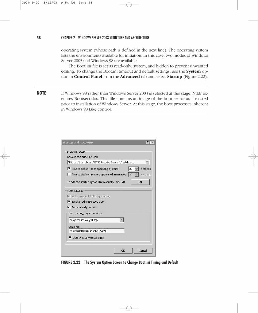
The Boot.ini file is set as read-only, system, and hidden to prevent unwantedediting. To change the Boot.ini timeout and default settings, use the System op-tion in Control Panel from the Advanced tab and select Startup (Figure 2.22).
NOTE If Windows 98 rather than Windows Server 2003 is selected at this stage, Ntldr ex-ecutes Bootsect.dos. This file contains an image of the boot sector as it existedprior to installation of Windows Server. At this stage, the boot processes inherentin Windows 98 take control.
58 CHAPTER 2 WINDOWS SERVER 2003 STRUCTURE AND ARCHITECTURE
FIGURE 2.22 The System Option Screen to Change Boot.ini Timing and Default
3930 P-02 3/12/03 9:54 AM Page 58
CAUTION Dual booting, although obviously possible, is generally not recommended. A num-ber of security issues arise in a dual-boot environment. The dual boot is generallyused only if a legacy application is not supported by Windows Server 2003.
• The hardware configuration review. At this stage, information about the sys-tem and attached devices is gathered by Ntdetect.com. This information islater included in the Windows Server Registry as HKEY_LOCAL_MACHINE\HARDWARE.
• Kernel load and preliminary initialization. As dots are drawn across thecomputer screen, Windows Server loads the kernel with Ntosknrl.exe and thehardware abstraction layer’s Hal.dll. The Windows Server Registry HKEY-LOCAL_MACHINE\SYSTEM is then loaded. Ntldr loads device drivers with a value of0x0 and is specified in the Registry as HKEY_LOCAL_MACHINE\SYSTEM.
• Kernel initialization. The actual initialization of the kernel occurs when theblue screen appears and identifies the Windows Server version and build num-ber and your system configuration. Behind the scenes several activities occur.First, a Registry key for hardware is created from the gathered information asHKEY_LOCAL_MACHINE\HARDWARE. This is where hardware system specsand device interrupts are stored. A clone set of system references is createdand remains unchanged within the Registry HKEY_LOCAL_MACHINE\SYSTEM\Select subkey. The kernel initializes devices after scanning the Registry forHKEY_LOCAL_MACHINE\SYSTEM\CurrentControlSet\Services.
NOTE Depending on severity, the boot process may continue or fail if errors are detectedin the initialization of devices. There are four levels of error control values. With anErrorValue of 0x0, the boot process continues uninterrupted. An ErrorValue of 0x1is not sufficiently critical to halt the boot process, but warning messages are dis-played. A severe ErrorValue of 0x3 causes a failure in the boot process. At thisstage, the system automatically restarts and uses the LastKnownGood control set,and then continues the boot process. The critical ErrorValue of 0x4 halts theprocess and attempts to restart, as with 0x3. A 0x4 message will then be displayedif the LastKnownGood control set also is defective.
• Starting of services. The Session Manager (smss.exe) launches the subsystemsand services that are defined to start immediately.
• User logon. The Win32 subsystem starts the Winlogon.exe and then the LocalSecurity Authority (lsass.exe). The Service Controller scans the HKEY_LOCAL_
The Boot Process 59
3930 P-02 3/12/03 9:54 AM Page 59
MACHINE\SYSTEM\Set\Services subkey for all service start entries. Two addi-tional subkeys are scanned: DependOnGroup and DependOnService. The sys-tem is ready to use when the Begin Logon box appears with instructions topress CTRL+ALT+DEL to log on. Windows Server 2003 does not consider thestartup procedure complete until the first user has logged on.
NOTE During the initial boot phase, it is possible to enter an alternative boot sequenceand invoke the Advanced Menu system. When F8 is pressed during the initial se-quences, the Advanced menu is displayed, which is used strictly for repair andmaintenance activities. It permits you to invoke the system in safe mode, EnableBoot Logging, Enable VGA Mode, or Last Known Good configurations. In the “Dis-aster Management” section of Chapter 14, we discuss how these options are ap-plied. We also discuss other system recovery methods.
THE WINDOWS SERVER 2003 REGISTRY
The Windows Server 2003 Registry is a database that contains operating system,hardware, and software information for the local computer system. It is used bymany programs, including the Windows Server kernel, device drivers, setup, anddetection executables. One example of the type of information stored in the Reg-istry is a list of all properly installed applications. Therefore, when you double-clicka file name with the Windows Server Explorer, its extension is matched with a listof installed applications and launches the appropriate software. Other itemsstored in the Registry include:
• Hardware configuration data
• Program group and desktop settings for each user
• User profile data
• Local language and time settings
• Network configuration data
• Security information for users and groups
• ActiveX and OLE server data
NOTE The relationship between the Registry and the Active Directory is very close. TheRegistry maintains information for the local system, and the Active Directory pro-vides object information about the domain network as a whole.
60 CHAPTER 2 WINDOWS SERVER 2003 STRUCTURE AND ARCHITECTURE
3930 P-02 3/12/03 9:54 AM Page 60

The Registry StructureThe Registry is based on a logical hierarchy of information, beginning with five sub-trees known as keys. The concept of keys and subkeys follows the same principleas folders and subfolders within a directory tree. Every key and subkey has at leastone entry that contains its name, data type, and configuration value (Table 2.3).
The keys and subkeys are stored in collections known as hives. Hive files arestored in %systemroot%\System32\Config or for user data in \%systemroot%\Profile\username. When changes are made to the Registry data, the data is com-pared to the logs before it is written. The log file is written first in a type of datastreaming mechanism. When it is saved to disk, changes are updated to the hivekey components. In this way, hive information is coupled with associated log filesin an effort to minimize corruption.
If the Registry is lost or damaged, Windows Server 2003 cannot function.Therefore, its care and feeding is a critical system administrator responsibility. Thefirst rule is to retain an emergency copy of the Registry in case of damage or loss.As stated previously, the Registry information is found in %systemroot%\Sys-tem32\Config, where %systemroot% is the root directory for a system, such as\winnt. For system recovery, the Windows Server Setup program also creates a%systemroot%\Repair folder that contains the following files:
• Autoexec.nt—a copy of %systemroot%\System32\Autoexec.nt used to initial-ize the MS-DOS environment.
• Config.nt—a copy of %systemroot%\System32\Config.nt used to initialize theMS-DOS environment.
The Windows Server 2003 Registry 61
TABLE 2.3 Registry Keys
Key Description
HKEY_LOCAL_MACHINE Information about the local system such as hardwareand operating system data; major keys are hardware,SAM, security, software, and system.
HKEY_CLASSES_ROOT File allocation and OLE/ActiveX data; includesassociation of extensions to applications.
HKEY_CURRENT_CONFIG System startup configuration that permits changes todevice settings.
HKEY_CURRENT_USER Profile for current active user as well as console, ControlPanel, environment, printer, and software data.
HKEY_USERS Profiles for all active users as well as default profile.
3930 P-02 3/12/03 9:54 AM Page 61

• Default—the Registry key HKEY_USERS\DEFAULT in compressed format.
• Ntuser.DA—A compressed version of %systemroot%\Profiles\DefaultUser\Ntuser.dat. The process uses Ntuser.da_ if this area needs repair.
• Sam—The Registry key HKEY_LOCAL_MACHINE\SAM in compressed format.
• Security—The Registry key HKEY_LOCAL_MACHINE\SECURITY in com-pressed format.
• Setup.log—The log of installed files with cyclic redundancy check (CRC) data.This file is read-only, system, and hidden by default.
• Software—the Registry key HKEY_LOCAL_MACHINE\SOFTWARE in com-pressed format.
• System—the Registry key HKEY_LOCAL_MACHINE\SYSTEM in compressedformat.
During system startup, the Windows Server kernel extracts information fromthe Registry, such as which device drivers to load and their load order. TheNtoskrnl.exe program also passes other information, including its version num-ber, to the registry.
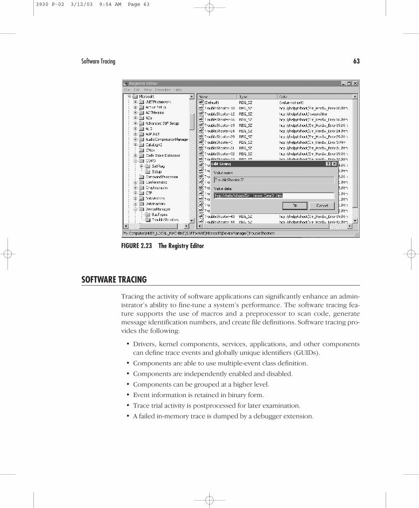
The Registry EditorSystem administrators may find it necessary to regularly view and edit the Registry.The Registry Editor tool (regedt32.exe) is located in the \System32 directory. Gen-erally speaking, it is best to use the Windows Server administrative tools to resolvesystem issues prior to editing the Registry. However, from time to time, it is nec-essary to go to the source of system data. That is when the Registry Editor (Figure2.23) comes into play.
NOTE The older style regedit is no longer supported. If regedit is invoked from the com-mand prompt, regedit32 is automatically invoked.
CAUTION The Registry Editor is not a toy. Its improper use can result in fatal system behavior.When viewing and copying the Registry, always turn the Editor to read-only mode.When directly editing, always think twice before entering information. The Reg-istry Editor automatically saves all changes, so once they are entered you must livewith the consequences. Changes are reflected automatically.
62 CHAPTER 2 WINDOWS SERVER 2003 STRUCTURE AND ARCHITECTURE
3930 P-02 3/12/03 9:54 AM Page 62
SOFTWARE TRACING
Tracing the activity of software applications can significantly enhance an admin-istrator’s ability to fine-tune a system’s performance. The software tracing fea-ture supports the use of macros and a preprocessor to scan code, generatemessage identification numbers, and create file definitions. Software tracing pro-vides the following:
• Drivers, kernel components, services, applications, and other componentscan define trace events and globally unique identifiers (GUIDs).
• Components are able to use multiple-event class definition.
• Components are independently enabled and disabled.
• Components can be grouped at a higher level.
• Event information is retained in binary form.
• Trace trial activity is postprocessed for later examination.
• A failed in-memory trace is dumped by a debugger extension.
Software Tracing 63
FIGURE 2.23 The Registry Editor
3930 P-02 3/12/03 9:54 AM Page 63
In the event of a system dump, a kernel debugger extension displays the traceelements that remain in memory. Software tracing is invoked by Start → Control
Panel → Performance and Maintenance → Administrative Tools → Perfor-
mance → Performance Logs and Alerts → Trace Logs.
VIEWING APPLICATION DEPENDENCIES
Anytime an application fails to execute properly or fails to load, a support tool inthe Windows Server 2003 Resource Kit, called the Dependency Walker, can be anexcellent analytical utility. It shows the minimum set of files required to run an ap-plication or load a DLL, and it shows which functions are exposed by a particularmodule and which ones are called by other modules. Moreover, it illustrates thefull path of all modules being loaded by an application, plus their base addresses.When an application fails, the Dependency Walker provides an error messageabout the problematic components.
The Dependency Walker operates by recursively scanning all dependent mod-ules required by an application. Missing files are detected first; then corrected orinvalid files are identified. For example, a 16-bit version of a DLL might be presentwhen a 32-bit version is required. Circular redundancy problems and CPU mis-matches are also detected during the recursive scans.
The Dependency Walker (Figure 2.24) identifies different types of dependen-cies between modules, which are briefly described in Table 2.4.
To review an application’s dependencies, load the Dependency Walker from theStart menu → choose Programs → Windows Server 2003 Support Services
→ Tools. From the Files menu select Open and browse to the desired applicationor DLL.
The Dependency Walker can also be used for application profiling. This tech-nique permits it to detect dynamically loaded modules in a running applicationthat may not be reported in the static import tables. The profiler is also used to de-tect that a module has failed to initialize. This activity is initiated once an applica-tion is loaded into the Dependency Walker. From the Profile menu, select Start
Profiling. You will then need to select the options from the Profile Module di-alog box. Continue the process until the desired information is obtained. To ter-minate the analysis, select the Profile menu → Stop Profiling.
NOTE The Windows Server 2003 Resource Kit also supplies a command-line method oflaunching the Dependency Walker through the depend.exe command-line utility.
Figure 2.25 displays the dialog box that permits the selection of the stable op-eration system for a given application.
64 CHAPTER 2 WINDOWS SERVER 2003 STRUCTURE AND ARCHITECTURE
3930 P-02 3/12/03 9:54 AM Page 64

Viewing Application Dependencies 65
FIGURE 2.24 The Windows Server 2003 Resource Kit’s Dependency Walker
TABLE 2.4 Types of Dependency between Modules
Type Description
Implicit A load-time dependency in which one module calls functions inanother module. Even if no direct calls are made to the secondmodule, that module is still loaded into memory.
Delay-Load A dynamic dependency in which a module is loaded only when aspecific call is made to it by the application.
Forward A dependency in which an application calls a function in a dependentmodule that is actually available from another module. The call isforwarded from the second module to the third module.
Explicit A run-time dependency, that is, a dynamic load of library functionscommon to OCXs, COM objects, and Visual Basic applications.
System Hook A dependency that occurs when a specific application action isundertaken; for example, the use of a mouse will result in a newprocess.
3930 P-02 3/12/03 9:54 AM Page 65
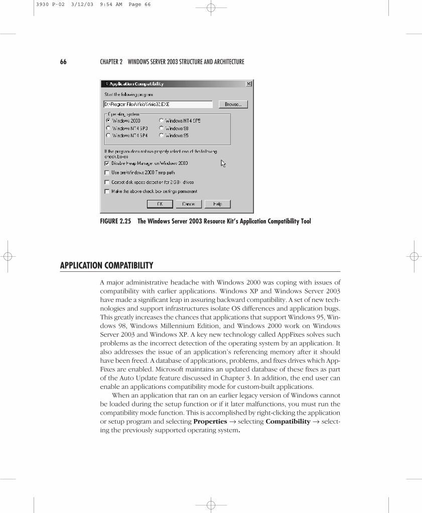
APPLICATION COMPATIBILITY
A major administrative headache with Windows 2000 was coping with issues ofcompatibility with earlier applications. Windows XP and Windows Server 2003have made a significant leap in assuring backward compatibility. A set of new tech-nologies and support infrastructures isolate OS differences and application bugs.This greatly increases the chances that applications that support Windows 95, Win-dows 98, Windows Millennium Edition, and Windows 2000 work on WindowsServer 2003 and Windows XP. A key new technology called AppFixes solves suchproblems as the incorrect detection of the operating system by an application. Italso addresses the issue of an application’s referencing memory after it shouldhave been freed. A database of applications, problems, and fixes drives which App-Fixes are enabled. Microsoft maintains an updated database of these fixes as partof the Auto Update feature discussed in Chapter 3. In addition, the end user canenable an applications compatibility mode for custom-built applications.
When an application that ran on an earlier legacy version of Windows cannotbe loaded during the setup function or if it later malfunctions, you must run thecompatibility mode function. This is accomplished by right-clicking the applicationor setup program and selecting Properties → selecting Compatibility → select-ing the previously supported operating system.
66 CHAPTER 2 WINDOWS SERVER 2003 STRUCTURE AND ARCHITECTURE
FIGURE 2.25 The Windows Server 2003 Resource Kit’s Application Compatibility Tool
3930 P-02 3/12/03 9:54 AM Page 66

NOTE A common duty of a system administrator is to manage software versions andbuilds. This responsibility is extremely time consuming and often accomplished ina less than methodical manner. Software tracing provides a means to minimize theneed for checked builds. With this feature, participating components—such as adriver, kernel component, service, or application—can define their own traceevents and GUIDs. As such, components can have multiple event classes definedand independently enabled or disabled. Each event retains its binary form. A traceactivity can be examined while it is occurring or after the event. If the system failsthe in-memory trace, it can be dumped by a debugger extension or reviewed in anappropriate tool. There is also a kernel debugger extension that has the ability todisplay the trace elements that remain in memory at the time of a break point ora system crash, or from a crash dump. This feature is invoked via Start → Control
Panel → Performance and Maintenance → Administrative Tools → Com-
puter Management.
Unauthorized ApplicationsThe Windows installer has a group policy configuration that prevents anyone ex-cept administrators from installing non-elevated applications. In versions of Win-dows server products prior to Windows Server 2003, this option was not enabledby default. Windows Server 2003 enables this feature by default in order to ensuregreater security out of the box.
INTELLIMIRROR AND OTHER INNOVATIONS
Prior to moving on to installation of Windows Server 2003, several other innova-tions should be highlighted. Specifically, the manner in which IntelliMirror, Re-mote OS Installation, and System Management Server interplay may affect the wayWindows Server is installed and administered.
IntelliMirror technology should be regarded as a collection of functions ratherthan a specific application. Microsoft simply calls IntelliMirror the “follow me” func-tion. In an Active Directory environment, system settings, applications, and datawill move with the user regardless of which physical computer system the user logson to. IntelliMirror was built on the original Zero Administration Initiative in orderto minimize management costs associated with user frustration in moving betweencomputers or coping with system failures. For example, if a user accidentallyremoves a critical dynamic-link library (.dll), IntelliMirror can be configured toseek out that component and automatically reinstall it when the application islaunched. Yet another example is a user who moves between physical locations, as
Intellimirror and Other Innovations 67
3930 P-02 3/12/03 9:54 AM Page 67
is common for consulting, sales, and technical support personnel. When such auser logs on to a computer in a different location, IntelliMirror will launch thesame desktop environment and data access as would be available in the home office.In the broadest terms, IntelliMirror provides three basic functions:
1. Management of desktop settings including any customizations and restrictions
2. Software maintenance and installation including configuration, repair, and ap-plication removal known as the Software Installation and Maintenance Feature
3. User data access and management including policies that define propertiesand the location of user folders
Remote OS Installation is a set of technologies that supports administration ofWindows Server 2003 client installation and configuration. It supports the new Pre-boot eXecution Environment (PXE) remote boot technology, which requests aninstallation of Windows XP from a delegated server. (Using Remote OS Installationis not recommended for Windows Server 2003 because of the number of configu-ration issues involved.) The specific application of these technologies is discussedin the next chapter. Coupled with IntelliMirror, Remote OS Installation facilitatesthe rollout of the Windows Server 2003 operating system and then automaticallycreates and maintains end-user applications and settings.
The final ingredient in the scenario is the optional System Management Server(SMS version 2.0 with Service Pack 2 or higher), which is discussed in greater de-tail in Chapter 17. SMS can be used to perform enterprise-wide inventory and trou-bleshooting. This includes management of systems other than Windows Server.
Each of these technologies offers the system administrator different advan-tages. The Remote OS Installation permits automatic installation and repair of Win-dows XP client systems. IntelliMirror provides a “just-in-time” approach to softwareinstallation and user environment management. SMS provides an advanced set ofjust-in-time applications for application deployment and system management. Asystem administrator should take a careful look at each of these technologies andapply them to more efficient management of client environments.
POSTSCRIPT
In this chapter we provided a view of Windows Server 2003 basic architecture. Thechapter did not attempt to view this OS in a networked or enterprise environment.Instead, we examined the basic operating system internals and provided informa-tion about several useful system administration tools. System administrators needthis high-level perspective to manage more demanding system issues. Subsequentchapters will expand on the topics reviewed here.
68 CHAPTER 2 WINDOWS SERVER 2003 STRUCTURE AND ARCHITECTURE
3930 P-02 3/12/03 9:54 AM Page 68