Windows 95, 98, Me, NT, 2000 and XP are registered ... Reset ... maintenance/repair session and...
48
Transcript of Windows 95, 98, Me, NT, 2000 and XP are registered ... Reset ... maintenance/repair session and...


Windows 95, 98, Me, NT, 2000 and XP are registered trademarks/products of Microsoft Corporation E-Series Escalator, E-Series 5000, E-Series HR, and E-Series TR are trademarks of the KONE Corporation. WORLD electronics, the WORLD electronics’ logo, FREEDOM Tool, and FREEDOMWare are registered trademarks of WORLD electronics Sales and Service, Inc. All other trademarks mentioned in this manual are the sole property of their respective manufacturers.
Copyright © 2004 by WORLD electronics®. All rights reserved. Printed in the United States of America. No part of this publication may be reproduced or distributed in any form or by any means, or stored in a database or retrieval system, without the prior written permission of WORLD electronics. Further, this publication and features described herein are subject to change without notice from publisher

Table of Contents
1
Introduction
Features................................................................. 2 Requirements............................................................ 2 How to Contact WORLD electronics................................... 3 Getting Started......................................................... 4
Security Device Information ............................................................................................................4 Installing FREEDOMWare Software Modules..........................................................................4 Executing the Software Module for the KONE, ES-5000 Escalator .............................5
General Description..................................................... 8 Communication Port Set-Up Window .............................................................................................9 Security Key Info Window.................................................................................................................12
Logon Procedure ........................................................ 14 Main Window ............................................................ 16
Communication Screen .........................................................................................................................16 Menu.............................................................................................................................................................17 Pushbuttons ..............................................................................................................................................18
System Information .................................................... 19 Option..........................................................................................................................................................19
View Parameters .............................................................................................................................19 Modify Parms ...................................................................................................................................21 Passenger Flow ................................................................................................................................33
Timer ...........................................................................................................................................................35 View Time Clock ..............................................................................................................................35 Mod time Clock ................................................................................................................................35 Reset Run Time ...............................................................................................................................36
Debug...........................................................................................................................................................37 Reset Logs.........................................................................................................................................37 Escalator Mode ...............................................................................................................................38
Mode ............................................................................................................................................................38 Manual Reset....................................................................................................................................38 Master Reset...................................................................................................................................39 Test Speed Detect........................................................................................................................39 Download Data .................................................................................................................................40
Log.................................................................................................................................................................41 View Faults ........................................................................................................................................42 View Events.......................................................................................................................................42 View Stopping...................................................................................................................................45 View Loading.....................................................................................................................................45 View Run Time..................................................................................................................................46

Introduction
2
Introduction: The FREEDOM Tool is a sophisticated software tool that allows the operator to service various elevators and escalators and their respective control systems. The software allows the operator to simultaneously view independent operations within the elevator/escalator system by opening windows to those systems/operations of interest. The selected windows may be left open during the maintenance/repair session and accessed when desired. Features: The FREEDOM Tool is a Graphical User Interface (GUI) and provides all the functions necessary to service the KONE (aka. Montgomery) ES-5000 escalator control systems. The software runs under the Microsoft Windows operating system and provides the following features: Ø A Graphical User Interface which makes it easy to access various adjustment and diagnostic
areas comprising the service tool resident upon the KONE ES-5000 escalator control system being diagnosed.
Ø Simple point and click operations. The computer does all of the necessary commands for the
user in the background. Requirements: The software, provided as a package by WORLD electronics, is designed to operate on an IBM compatible notebook computer that has the following minimum characteristics: Ø Windows 9x, Me, 2000, NT, or XP Operating System (NOTE: This software will not work on
Window 3.1) Ø Mouse, Trackball, or other pointing device Ø DB-9 RS232 Serial Port Ø DB-25 Parallel Port Ø Floppy Disk or CD-ROM Drive Ø Approximately 15MB of Free Hard Disk Drive Space
The FREEDOM Tool software is not capable of being executed without a sophisticated security key that is to be connected to the parallel port of the computer at the time of the FREEDOM Tool execution. A WORLD electronics “FREEDOM Tool Serial Interface Cable” (7502-9031) is required. This interface cable provides the proper signal conversions and connections between the computer and the KONE ES-5000 escalator system that allows them to communicate to one another.

How to Contact WORLD electronics
3
How to contact WORLD electronics If you are having any problems operating the FREEDOM Tool, feel free to contact us at the following location. We value you as a customer and welcome any comments concerning the use of the FREEDOM Tool. WORLD electronics Phone: 800-523-0427 3000 Kutztown Road 610-939-9800 Reading, PA 19605 Fax: 610-939-9895 E-Mail: Elevator Sales [email protected] Service: [email protected] FREEDOM Tool [email protected] Website: www.world-electronics.com
When calling WORLD electronics for assistance, have your product serial number, the model computer being used, operating system type, and the error description ready.

Getting Started
4
Getting Started Security Device Information: WORLD electronics protects itself and its FREEDOM Tool Software by utilizing a sophisticated security device that must be installed on the parallel printer port, physically located in the rear of most laptop computers. Connect this security key before operating the FREEDOM Tool Software. This security key is unique to every FREEDOM Tool and cannot be shared among other FREEDOM Tools. WARNING! – It is extremely important this device is not lost. The replacement value of this device is equal to the dollar value of the FREEDOM Tool software modules purchased from WORLD electronics. This cost is in THOUSANDS of dollars. Please take the steps necessary to safeguard yourself against loss of the security device. To prevent theft, it is advisable to store the security device and the FREEDOM Tool in 2 separate, secure locations when not in use. DO NOT PLUG THE SECURITY KEY INTO THE ELEVATOR AT ANY TIME. ONLY PLUG THE SECURITY KEY INTO THE LAPTOP COMPUTER. A damaged security key has a $250 charge affiliated with its replacement.
Installing FREEDOMWare Software Modules: All FREEDOMWare Software modules are available on 2 forms of media. These forms are Floppy Diskette and CD-ROM. Please note, the Floppy Diskette format is only available upon request.
To install the FREEDOMWare Software module from a CD-ROM: 1) Insert CD-ROM into the laptop computer’s CD-ROM Drive Bay. 2) The software should run by itself opening a window similar to the one seen in Figure 1.
If the software does not AutoRun:
1) Select Start 2) Select Run 3) Type the following into the field: d:\install.exe (replace “d:” with the letter of the CD-
ROM Drive – typically “d:”, “e:”, or “f:”) 4) Click “OK” and the Install program will launch by opening a window similar to the one
seen in FIGURE X1. 5) Using the Install program click on the button labeled “Install” beside the name of the
software module that is desired to be installed. 6) Note that the security key serial number will be requested during the installation. This
number can be found on the security key or on the outside of the Software Module product box.
7) The user will be notified on the screen when the installation is complete

Getting Started
5
Figure 1
To install the FREEDOMWare software module from a Floppy Disk:
1) Insert Diskette 1 of 3 for the desired software module into the floppy disk drive of the laptop computer.
2) Select Start 3) Select Run 4) Type the following into the field: a:\setup.exe 5) Click “OK” and the Software Module Installation program will launch giving the user on-
screen instructions for installing the desired FREEDOMWare Software module. 6) Note that the security key serial number will be requested during the installation. This
number can be found on the security key or on the outside of the Software Module product box.
7) The user will be notified when the other diskettes will be needed for insertion. 8) A dialog will appear at the end of the installation informing the user as to the success of the
application installation.
Executing the Software Module for the KONE: ES-5000 Escalator The start up procedure for the WORLD electronics’ FREEDOM Tool is described as follows:
1) Make sure the security key is installed on the parallel port of the computer. This should ideally

Getting Started
6
be done when the power is turned off to the laptop PC. If there is any confusion as to the appearance of the security key device, please refer to the picture on the very first page of this manual.
2) If the computer is not already turned on, turn it on by pressing the laptop computer’s power button. The location of this button can be found in the owner’s manual for the laptop PC being used.
3) With the Windows 9x, Me, NT, 2000, XP operating system functioning, the FREEDOM Tool Shell program can be invoked using either of 2 methods. The first is by moving the PC’s pointing device cursor over top of the “FREEDOM Tool” icon and then double-click. The second method would be by selecting the Start, FREEDOM Tool folder, and then FREEDOM Tool. Please refer to Figure 2.
Figure 2
4) After performing one of the methods described in Step 3 a window should appear with the title “FREEDOM Tool – Version X.XX”. X.XX is the current version number of the software being run. Refer to Figure 3.

Getting Started
7
Figure 3
5) On the menu of the FREEDOM Tool program is a choice labeled “KONE”. Maneuver the
pointing device over the top of the name KONE and click one time with the mouse button. 6) This will drop down a list of elevator/escalator control system that WORLD electronics has
developed FREEDOMWare Software modules. Move the mouse cursor over top of “ES-5000 Escalator” and click 1 time. The software module should run at this time.

General Description
8
General Description: The FREEDOM Tool is a multi- functional diagnostic and adjustment tool that allows the user to do everything from diagnosing faults to setting up the controller system. All software functions can be accessed from the FREEDOM Tool’s Main Window as seen in Figure 4.
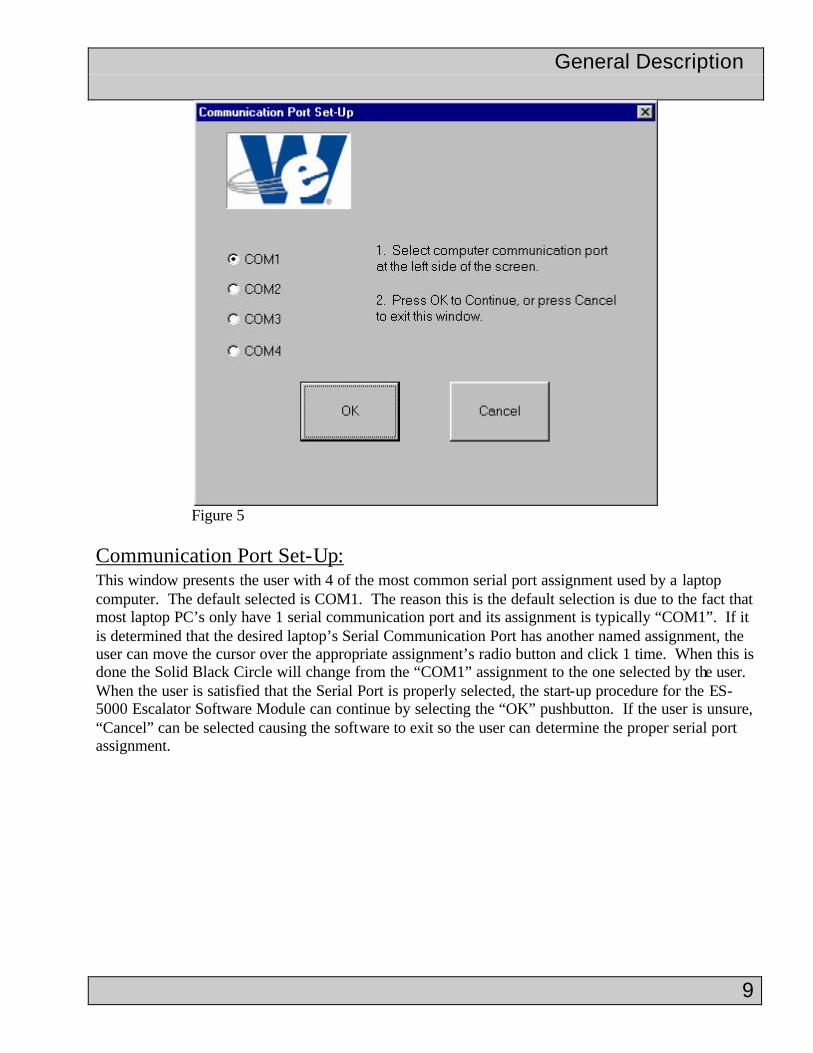
Figure 4 Before the FREEDOM Tool’s Main Window will open a series of windows will appear allowing the user to choose the communication port used on the laptop and end with a check of the Security Key ensuring the proper security key is plugged into the laptop’s parallel port. Figure 5 shows the Communication Port Set-Up window.
General Description
9
Figure 5
Communication Port Set-Up: This window presents the user with 4 of the most common serial port assignment used by a laptop computer. The default selected is COM1. The reason this is the default selection is due to the fact that most laptop PC’s only have 1 serial communication port and its assignment is typically “COM1”. If it is determined that the desired laptop’s Serial Communication Port has another named assignment, the user can move the cursor over the appropriate assignment’s radio button and click 1 time. When this is done the Solid Black Circle will change from the “COM1” assignment to the one selected by the user. When the user is satisfied that the Serial Port is properly selected, the start-up procedure for the ES-5000 Escalator Software Module can continue by selecting the “OK” pushbutton. If the user is unsure, “Cancel” can be selected causing the software to exit so the user can determine the proper serial port assignment.

General Description
10
Figure 6 When OK is selected and the system properly configures the laptop’s serial port, a window similar to Figure 6 opens. If the window seen in Figure 6 does not appear, then an error message will appear informing the user of a problem in opening the serial port. This message window is seen in Figure 7.
Figure 7
After OK is selected another message window will appear stating that for the software to operate correctly, a serial port must be properly selected. Figure 8 shows this message window.

General Description
11
Figure 8 The message window depicted in Figure 8 gives the user 2 choices, OK and Cancel. If the user desires to exit the software to determine which Serial Port should be selected then the choice “Cancel” should be selected with the laptop’s pointing device. Otherwise the “OK” pushbutton should be selected to re-open the Communication Port Set-Up Window, a second time, to select a different serial port. If the software still cannot configure the serial port, another message window will appear informing the user of an error opening the communication port. Upon selecting OK in this message window, the software will terminate. If on the second attempt the software is able to configure the serial port, the Security Key Info window will appear as in Figure 9.
Figure 9

General Description
12
Security Key Info: Figure 9 depicts the second step in starting up the ES-5000 software module. The second step involves detecting the presence of a software security device and verifying that the contents belong with the currently installed software. If a security key is found and its contents are verified to be valid, the Security Key Info window will inform the user that the Security Check passed by showing a picture of a security key with a green border, similar to what is seen in Figure 9. Also the box beside Software Security Check will say “PASSED”, and the Expiration Date Box will show the date the security key expires or will say “NONE”. PLEASE NOTE: all security keys are initially programmed with a 30 day expiration. Once the tool has been paid for, WORLD electronics will then provide a code that will remove this expiration date and set the expiration date information field to NONE. Other information that can be found in the Security Key Info window is: Name of the software, Software Version Number, WORLD electronics’ phone number for technical support, and WORLD electronics’ website. When calling WORLD electronics, it is advisable to have all information found in this window available since it will aid in diagnosing any problems the Software Module may have. Also located in the Security Key Info window are instructions for connecting the Interface cable to the Escalator Controller and logging the tool onto the escalator control system. At the bottom right hand corner of the Security Key Info window is a pushbutton labeled “OK”. Moving the mouse pointer over top of the OK pushbutton and clicking one time will close the Security Key Info window and open the FREEDOMWare: ES-5000 Software Module’s main window.
Figure 10

General Description
13
If the security key cannot be located, or the information contained within the key is incorrect, the Security Key Info Window will appear similar to the one seen in Figure 10. The first sign that there is an error with the security key is the picture of the security key surrounded by a red border. Also the Security Key Information block will indicate that the Security Key Check “FAILED” and an Authorization Error Number will appear. The Security Key Info window will indicate that a Security Key Error was detected and it instructs the user to contact WORLD electronics. A pushbutton labeled “DEMO MODE” is provided to allow the user to proceed on to the ES-5000 Software Module’s main window. The Demonstration Mode for the ES-5000 will allow the user to view the Main Window and its various functions, but it will not be able to communicate with the escalator control system. In the lower, right-hand corner is a pushbutton labeled “OK”. The OK pushbutton will cause the software to terminate, and return the user back to the Windows desktop screen.

Logon Procedure
14
After selecting OK in the Security Key Info window, and there is no problems found with the security key, a window similar to Figure 11 will appear. This window is the FREEDOMWare ES-5000 Software Module’s main window.
Figure 11 When the user first invokes the ES-5000 software module, a Logon procedure must be followed. The need to perform a Logon procedure is signaled by the text “PRESS LOGON”, seen below the LOGON pushbutton in Figure 11. The following describes the Logon procedure. Logon Procedure: Whenever the user connects the ES-5000 FREEDOM Tool to the escalator, the escalator requires the tool to follow a very precise Logon procedure where several handshaking protocols are followed. The ES-5000 Software Module does this required handshaking automatically whenever the user depresses the pushbutton labeled LOGON on the ES-5000 Software Module’s main window. As mentioned earlier, there are several handshaking protocols that are performed in the background, the text field found beneath the LOGON pushbutton indicates to the user where the ES-5000 Software Module is within this handshaking algorithm.

Logon Procedure
15
Each level of handshaking performed by the ES-5000 Software Module is called a step. The steps that the ES-5000 Software Module follows are labeled as follows: LOGON STEP 1, LOGON STEP 3, LOGON STEP 5, LOGON STEP 7, and LOGON STEP 9. It is not important for the user to know what each Logon step does, but, be aware, each logon step has a timeout period associated. If at any time this timeout period should expire before the logon procedure gets to the next step, a message window similar to what is seen in Figure 12 will appear.
Figure 12 The message seen in Figure 12 informs the user that the Logon procedure has failed. It also reminds the user to the most prominent reason for a Logon failure, improper connections with the interface box. It is necessary for the user to pay attention to the text messages provided underneath the LOGON pushbutton. The reason for this is that, a WORLD electronics technical service representative will require this information when attempting to diagnose the problem the user is encountering. Please note: If the escalator controller believes a unit is logged on, it will not allow another logon to occur. Therefore it may be necessary to attempt a LOGON 3-4 times before success. If time is a factor, it is possible to reset the escalator system by cycling the power to the ES-5000 escalator controller. When the user selects the OK pushbutton within the LOGON FAILURE message box, the software will exit. In order for the user to attempt to Logon to the system again, it is necessary for the FREEDOM Tool ES-5000 Software Module to be re-run. Upon a successful Logon, the text message area underneath the LOGON push button will say “LOGGED ON”, and the LOGON pushbutton will disappear. The Communication Screen found at the top of the Main Window will now have the text “SELECT FUNCTION”. This is represented in Figure 13. At this time the user can access all functions provided through the ES-5000 Software Module.

Main Window
16
Figure 13 Main Window: The Main Window gives the user access to all information provided by the KONE ES-5000 escalator Control System. Access to this information is provided in the form of the Communication Screen, pushbuttons, and menu choices. These objects are described as follows: Communication Screen: The Communication Screen found within the Main Window of the FREEDOM Tool displays ALL information received from the tool residing within the escalator controller. The FREEDOM Tool does not generate any of the information seen within this screen on its own. The Communication Screen is comprised of 5 rows. Each row can contain up to 20 characters. The data streams coming from the escalator inform the FREEDOM Tool as to where to place the individual data characters. This includes information on clearing old characters from the screen. If for some reason a row of characters is not cleaned out or the user wants to manually clear out individual lines or the entire screen, 5 buttons have been placed at the end of each individual line and 1 additional button has been placed at the lower, right-hand corner of the Communication Screen. These 5 button located at the end of each
Main Window
17
individual row will clear the contents of every character location found within that selected row. The individual button found in the lower, right-hand corner of the Communication Screen will clear the contents of the entire Communication Screen. Please note: This does not log the tool off from the Escalator. By selecting one of the “Action” or “Function” pushbuttons, the Communication Screen will update with new information. Menu: The FREEDOM Tool: ES-5000 Escalator Software Module’s menu is broken down into five parts. These parts are File, Keypad, Functions, Actions, and About. Each of these menu categories contains commands that cause the FREEDOM Tool to perform an action. These actions can be anywhere from commanding the tool within the escalator control system to perform a task to opening a window that allows the user to change what port on the laptop PC is used for communicating with the escalator controller. The following section describes each of the menu categories and their individual functions contained within.
File The first of the five menu groups, File lets the user exit out of the ES-5000 Escalator Software Module, set-up which laptop serial ports is used for communication, and start the logon process. This is accomplished through the menu choices Exit, Communications, and Logon respectively.
Keypad
The keypad contains items for handling all numerical and response entries within the software module. The keypad menu selections consist of the numbers 0 through 9, the hexadecimal numbers A through F, and a decimal point. The Keypad menu selection also contains the response keys Yes, No, Up, Down, Backspace, and Enter.
Functions
Function selections are used after the user enters into one of the “Action” modes. There are a total of 8 function keys used within the ES-5000 Escalator Software Module. The most commonly used function keys are F4(Next) and F8(Exit). As the label beside these two function keys describes, the F4 function key will scroll the Communication Screen through displaying the next choice in a menu like progression and the F8 function key will exit the Communication Screen out of the currently selected mode and return back to the previous Communication Screen menu choice. In some of the Action modes, the F7 key will enable the user to proceed backwards through a list one item at a time. The F1, F2, F3, F4, and F6 function keys are generally used to activate sub functions within the Action modes.
Actions
Actions are functions found within the software comprising the service tool in the ES-5000 escalator control system. The Action functions that the ES-5000 escalator are as follows: Option, Timer, Debug, Mode, and Log. Each of these functions has selections that are made available to the user through the use of the previously mentioned “Function” selections. Each of these Action modes is described in greater detail later on in this manual.

Main Window
18
About
The About menu selection will open a window that gives version and contact information for the FREEDOM Tool: KONE ES-5000 Escalator Software Module.
Pushbuttons: An integral part to any Windows based Graphical User Interface is an item called the pushbutton. The FREEDOM Tool: ES-5000 Escalator Software Module has three main groups of pushbuttons. These three main groups could be called Keypad buttons, Function buttons, and Action buttons. Each of these three pushbutton categories contains commands that cause the FREEDOM Tool to perform an action. The three pushbutton categories are described briefly. Please refer to the System Information section of this manual for more information on the function of these pushbuttons.
Keypad The keypad pushbuttons contain items for handling all numerical and response entries within the software module. The keypad selections consist of the numbers 0 through 9, the hexadecimal numbers A through F, and a decimal point. The Keypad also contains the response keys Yes, No, Up, Down, Backspace, and Enter.
Functions
Function selections are used after the user enters into one of the “Action” modes. There are a total of 8 function keys used within the ES-5000 Escalator Software Module. The most commonly used function keys are F4(Next) and F8(Exit). As the label beside these two function keys describes, the F4 function key will scroll the Communication Screen through displaying the next choice in a menu like progression and the F8 function key will exit the Communication Screen out of the currently selected mode and return back to the previous Communication Screen menu choice. In some of the Action modes, the F7 key will enable the user to proceed backwards through a list one item at a time. The F1, F2, F3, F4, and F6 function keys are generally used to activate sub functions within the Action modes.
Actions
Actions are functions found within the software comprising the service tool in the ES-5000 escalator control system. The Action functions that the ES-5000 escalator are as follows: Option, Timer, Debug, Mode, and Log. Each of these functions has selections that are made available to the user through the use of the previously mentioned “Function” selections. Each of these Action modes is described in greater detail later on in this manual.

System Information Option
19
System Information: The following section presents the user instructions for using the FREEDOM Tool, ES-5000 Escalator Software Module. All information is presented in a state that is as accurate as possible. There may be situations from one escalator to the next where discrepancies arise. Any question on these discrepancies should be addressed to WORLD electronics. The ES-5000 software module has five modes of operation. These modes are: Option, Timer, Debug, Mode, and Log.
Option: All adjustments to the physical operation of the escalator are made through the Option selection on the main screen. When Option Mode is selected the Communication Screen will appear similar to the one in Figure 14.
F1 = VIEW PARAMETERS F1 – View Parameters F2 = MODIFY PARMS. F2 – Modify Parameters F3 = PASSENGER FLOW F3 – Passenger Flow F8 = EXIT Figure 14 F8 - Exit
The Option mode screen gives the user a couple of selection choices. These selections can be made using the Function buttons found on the FREEDOM Tool’s main window. The selections made available to the user in Option are: F1 – View Parameters, F2 – Modify Parms., F3 – Passenger Flow, and F8 – Exit.
F1 – VIEW PARAMETERS The first selection listed after selecting the Option pushbutton, View Parameters, is selected by depressing the F1 pushbutton on the keyboard or on the FREEDOM Tool’s Main Window. When F1 is selected the “View Parameters” menu will appear in the Communication Screen. The “View Parameters” function of the Option mode allows the user to view the operating parameters that have been programmed into the escalator. Figure 15 shows the View Parameters menu. This menu is broken into 3 sections. These 3 sections are: LWR ANNUNC SWS, UPR ANNUNC SWS, and Parameter List. The commands available to the user are: F1 for LWR ANNUNC SWS, F2 for UPR ANNUNC SWS, F4(NEXT) to view the Next adjustable parameter, F7 to view the previous adjustable parameter, and F8 to Exit the VIEW PARAMETERS menu.
VIEW PARAMETERS F1 – Lower Annunciator Switches F1 = LWR ANNUNC SWS F2 – Upper Annunciator Switches F2 = UPR ANNUNC SWS F4 – Next Parameter CONTRACT #: 0 F7 – Previous Parameter Figure 15 F8 - Exit View Lower Annunciator Switches: Selecting F1 in the View Parameters Screen will place the FREEDOM Tool into a mode where the Lower Annunciator Board safety switches can be viewed. The screen, shown in Figure 16,

System Information Option
20
shows the Communication Screen in the Main Window when the View Lower Annunciator Switch function is active.
VIEW LWR ANNUNC SWS F4 – View next switch assignment NO. OF SW’S = 18 F7 – View previous switch assignment 01/LR LEVEL STEP/M/F F8 – Exit Figure 16
The VIEW LWR ANNUNC SWS screen is comprised of 3 Lines. The first Line informs the user that the tool is currently in VIEW LWR ANNUNC SWS mode. Line 2 shows the total number of switches programmed into the Lower Annunciator Board (KONE P/N: P-24684). It is important to notice that the number of switches is limited to what is physically wired into the Lower Annunciator PCB Assembly. The information on Line 3 is separated into 4 distinct fields. Each field is separated by a “/” character. In Figure 16, the 01 indicates the switch number currently being viewed. This switch number can be moved to the previous or next switch by pressing the F7 or F4 button respectively. “LR LEVEL STEP” shown in the second field is the name of the switch that is wired into the first switch location on the Lower Annunciator circuit board. The third field shown on Line 3 indicates whether the programmed switch is programmed to be: “M” – manual reset or “N” -non-manual reset. Finally, the fourth field represented on Line 3 indicates whether the switch will be logged as an event(E) or a fault(F). Putting all of this data together, the switch shown in Figure 16 would be the first switch wired into the lower annunciator board. The switch is programmed to monitor the Lower Right Level Step Sensor. It is to be manually reset and will be logged in the Fault Log. Using the F8 key will exit the tool out of the VIEW LWR ANNUNC function and return to the VIEW PARAMETERS menu.
View Upper Annunciator Switches: Selecting F2 in the View Parameters Screen will place the FREEDOM Tool into a mode where the Upper Annunciator Board safety switches can be viewed. The screen, shown in Figure 17, shows the Communication Screen in the Main Window when the View Upper Annunciator Switch function is active.
VIEW UPR ANNUNC SWS F4 – View next switch assignment NO. OF SW’S = 13 F7 – View previous switch assignment 01/U PIT SWITCH /M/F F8 – Exit Figure 17
The VIEW UPR ANNUNC SWS screen is comprised of 3 Lines. The first Line informs the user that the tool is currently in VIEW UPR ANNUNC SWS mode. Line 2 shows the total number of switches programmed into the Upper Annunciator Board (KONE P/N: P-24684). It

System Information Option
21
is important to notice that the number of switches is limited to what is physically wired into the Upper Annunciator PCB Assembly.
The information on Line 3 is separated into 4 distinct fields. Each field is separated by a “/” character. In Figure 17, the 01 indicates the switch number currently being viewed. This switch number can be moved to the previous or next switch by pressing the F7 or F4 button respectively. “U PIT SWITCH” shown in the second field is the name of the switch that is wired into the first switch location on the Upper Annunciator circuit board. The third field shown on Line 3 indicates whether the programmed switch is programmed to be: “M” – manual reset or “N” -non-manual reset. Finally, the fourth field represented on Line 3 indicates whether the switch will be logged as an event(E) or a fault(F). Putting all of this data together, the switch shown in Figure 17 would be the first switch wired into the upper annunciator board. The switch is programmed to monitor the Upper Pit Safety Switch. It is to be manually reset and will be logged in the Fault Log. Using the F8 key will exit the tool out of the VIEW LWR ANNUNC function and return to the VIEW PARAMETERS menu. Parameter Scroll: While in the View Parameters menu, the user can look at the current programmed parameters used by the ES-5000 Escalator System. Line 4 of the VIEW PARAMETERS screen displays the ES-5000’s parameters. The user can scroll through these by using the F4 and F7 buttons. The F4 pushbutton will proceed to the next parameter on the parameter list, while the F7 pushbutton will display the previous parameter on the list. Parameters cannot be adjusted in the VIEW PARAMETERS menu. Table 1 shows the parameter list for the ES-5000 Escalator Control System. ESCALATOR ID ESC(1)/WALK(2) RISE WIDTH RATED SPEED # OF BRAKES TYPE OF BRAKES VAC # OF MOTORS HORSE POWER MOTOR RPM ENCODER PPR ENCODER FREQ BRAKE DELAY SENSOR PEAK DECEL RATE BURNISH CYCLES REMOTE MONITOR TIME BASE CHECK SOFT START HANDRAILS ENBLD BRANCH # OWNER’S #
Table 1
F2 – MODIFY PARMS.
Selecting the F2 pushbutton in the Option mode menu will place the FREEDOM TOOL into an adjustment function, indicated by the title MODIFY PARAMETERS on Line 1 of the Communication Screen. The MODIFY PARAMETERS function menu gives the user the ability to make adjustments to operating parameters and features of the ES-5000 Escalator Control System. Figure 18 shows the MODIFY PARAMETERS menu and the 3 adjusting sections made available to the user. These 3 sections are: LWR ANNUNC SWS, UPR ANNUNC SWS, and Parameter List. A fourth command, not displayed within the MODIFY PARAMETERS menu, is

System Information Option
22
RESET TO DEFAULT CONFIGURATION. These commands are made available to the user by selecting the following: F1 for LWR ANNUNC SWS, F2 for UPR ANNUNC SWS, F3 for Adjustable Parameter and F5 for RESET TO DEFAULT CONFIGURATION. To change the adjustable parameter displayed to the Next adjustable parameter, select F4. F7 is pressed to switch to the previous adjustable parameter, and F8 to Exit the MODIFY PARAMETERS menu.
F1 – Lower Annunciator Switches F2 – Upper Annunciator Switches MODIFY PARAMETERS F3 – Adjust Parameter F1 = LWR ANNUNC SWS F5 – Reset To Default Configuration F2 = UPR ANNUNC SWS F4 – Next Parameter F3 = CONTRACT # F7 – Previous Parameter Figure 18 F8 – Exit Lower Annunciator Switches: Selecting F1 in the Modify Parameters Screen will place the FREEDOM Tool into a mode where the Lower Annunciator Board safety switches can be adjusted. The screen, shown in Figure 19, shows the Communication Screen in the Main Window when the Modify Lower Annunciator Switch function is active.
F1 – Insert Lower Annunciator Switch F2 – Modify Existing Lower Annunc. Switch MODIFY LWR ANNUNC SW F3 – Delete Lower Annunciator Switch NO. OF SW’S = 14 LINE 3 FUNCTIONS 01/LR LEVEL STEP/M/F F4 – Next Lower Annunciator Switch F1=INS/F2=MOD/F3=DEL F7 – Previous Lower Annunciator Switch Figure 19 F8 – Exit The information presented to the user in the MODIFY LWR ANNUNC SW screen is identical to the information displayed in the VIEW LWR ANNUNC SWS screen. Line 4 of the MODIFY LWR ANNUNC SW screen is the exception. Line 4 present the user with 3 options. These three options are: F1 = INS, F2 = MOD, and F3 = DEL. These three commands are described in detail, as follows. F1 – INS
F1 places the MODIFY LWR ANNUNC SW function into Insert mode. Insert mode gives the user the ability to add a switch onto the Lower Annunciator Circuit board. The switch can be inserted anywhere as long as it falls into the range defined by the first switch to the last switch number plus 1. The upper limit for a switch number shown in the example given in Figure 19 would be 15. Figure 20 shows the Communication Screen when the MODIFY LWR ANNUNC SW function is placed into Insert Mode.

System Information Option
23
F1 – Insert switch as shown INSERT ON STRING 1 F4 – Change designated switch forward NO. OF SW’S = 13 F7 – Change designated switch backward 04/LR LEVEL STEP/N/F F8 – Exit without inserting switch F1=INSERT F8=EXIT Number Keys – Enter digits in Field 1 Figure 20 Up/Down/Yes/No – modify Fields 2, 3,4 Enter – Change to next field
When the user places the MODIFY LWR ANNUNC SW function into Insert Mode, Line 1 of the Communication Screen will update to show INSERT ON STRING 1. String 1 is the designated string for the Lower Annunciator PCB’s switches. The Communication Screen’s input focus shifts to the first field located on Line 3. Fields in Line 3 are divided by the “/” character. The first field is for the switch number. The switch number can be any number larger than 1 and less than the Number of Switches plus 1. The example shown in Figure 20 would have an upper limit of 14 switches. The switch number can be changed by using one of two methods. The first method would have the user select the switch number by scrolling through the switches using the F4(Next) and F7(Previous) keys until the desired switch location is displayed. To select that switch number the user would select the Enter pushbutton. The second method is typing the switch number in directly using the numerical keys. After punching in the second digit of the switch number or selecting Enter after using the F4/F7 keys, the input focus will move to the second field on Line 3.
The second field on Line 3 contains the switch name. Table 2 contains the Annunciator Switch names used by the ES-5000 Escalator system.
LL HRNLT LL SKIRT LL LEVEL STEP U MSD UR HRNLT U COMB IMPACT U UPTHRUST UR SKIRT BRAKE TEMP MOT PIT/INTLK U ACC. COVER UR LEVEL STEP UL LEVEL STEP UL SKIRT UL HRNLT U E-STOP U PIT SWITCH USTEP OUT POS MOTOR #1 TEMP MOTOR #2 TEMP SPECIAL 1 SPECIAL 2 SPECIAL 3 L UPTHRUST-S U UPTHRUST-S LL COMB IMPCT LR COMB IMPCT UL COMB IMPCT UR COMB IMPCT L MSD LR LEVEL STEP LR SKIRT L UPTHRUST LSTEP OUT POS L COMB IMPACT LR HRNLT LR STATION L PIT SWITCH L E-STOP L ACC. COVER LL STATION
Table 2
Annunciator switch names in field 2 of Line 3 in the Insert mode can be changed by using the Up or Down pushbutton selections. Once the desired switch label is displayed the user

System Information Option
24
selects the Enter pushbutton to proceed to the next information field. NOTE: Pressing the F4/F7 pushbuttons in this field will change the switch number.
The third field on Line 3 programs the selected annunciator switch to be either manual reset(M) or non-manual reset(N). The setting of manual reset or non-manual reset can be adjusted using the Yes/No pushbuttons. Yes will toggle the field to manual reset, represented by the letter “M”. The No pushbutton will assign the field an “N” character indicating that the switch is a non-manual reset type switch. To assign this setting to the selected annunciator switch, press the Enter pushbutton. This action will move the input focus to the fourth and final input field on Line 3.
The final input field on Line 3 indicates whether the switch will be logged as an event(E) or a fault(F). A switch that is set as an event(E) will place an entry into the Event Log within the Log screen selection whenever the assigned switch is activated. Assigning an annunciator switch as a fault(F) will create an entry in the ES-5000 Escalator control system’s Fault Log. This entry field can be assigned as a fault(F) by selecting the No and an event(E) by selecting Yes on the FREEDOM Tool’s main window.
After the user sets the event/fault field to the desired setting, the entire switch assignment can be programmed into the ES-5000 by pressing the F1 key. To abort inserting a switch, at any time, press the F8 pushbutton. If the switch number assigned is out of range, Line 4 of the Communication Screen will update similar to what is seen in Figure 21.
MODIFY LWR ANNUNC SW NO. OF SW’S = 16 18/LR LEVEL STEP/M/E SW. # OUT OF RANGE Figure 21
When “SW. # OUT OF RANGE” appears on Line 4, it is an indication that the selected switch number is incorrect and must be reassigned to a different switch number. The “Out of Range” error message will appear for approximately 5 seconds before returning the Insert String function to its original state. If the switch insertion is successful, the number of switches indicated on Line 2 of the MODIFY LWR ANNUNC SW function will have increased by 1. Refer to Figure 22. MODIFY LWR ANNUNC SW NO. OF SW’S = 15 01/LR LEVEL STEP/M/F F1=INS/F2=MOD/F3=DEL Figure 22
F2 – MOD
F2 places the MODIFY LWR ANNUNC SW function into Modify mode. Modify mode gives the user the ability to change the assignments made to a switch on the Lower

System Information Option
25
Annunciator Circuit board. Figure 23 shows the Communication Screen when the MODIFY LWR ANNUNC SW function is placed into Modify Mode. F1 – Modify switch as shown MODIFY LWR ANNUNC SW F4 – Change designated switch forward NO. OF SW’S = 12 F7 – Change designated switch backward 12/LL LEVEL STEP/M/F F8 – Exit without modifying switch F1=MODIFY F8=EXIT Figure 23 Up/Down/Yes/No – modify Fields 2, 3,4 Enter – Change to next field
When the user places the MODIFY LWR ANNUNC SW function into Modify Mode, the Communication Screen’s input focus shifts to the first field located on Line 3. Fields in Line 3 are divided by the “/” character. The first field is the switch number. The switch number can be any number in the range of switches programmed into the Lower Annunciator Board. The example shown in Figure 23 would have a range of 1 through 12. The switch number can be changed using the F4(Next) and F7(Previous) keys until the desired switch location is displayed. To select that switch number the user would select the Enter pushbutton. The second method is typing the switch number in directly using the numerical keys. After punching in the second digit of the switch number or selecting Enter after using the F4/F7 keys, the input focus will move to the second field on Line 3.
The second field on Line 3 contains the switch name. Table 2, on Page 23, contains the Annunciator Switch names used by the ES-5000 Escalator system. Annunciator switch names in field 2 of Line 3 in the Modify mode can be changed by using the Up or Down pushbutton selections. Once the desired switch label is displayed the user selects the Enter pushbutton to proceed to the next information field. NOTE: Pressing the F4/F7 pushbuttons in this field will change the switch number.
The third field on Line 3 programs the selected annunciator switch to be either manual reset(M) or non-manual reset(N). The setting of manual reset or non-manual reset can be adjusted using the Yes/No pushbuttons. Yes will toggle the field to manual reset, represented by the letter “M”. The No pushbutton will assign the field an “N” character indicating that the switch is a non-manual reset type switch. To assign this setting to the selected annunciator switch, press the Enter pushbutton. This action will move the input focus to the fourth and final input field on Line 3.

System Information Option
26
The final input field on Line 3 indicates whether the switch will be logged as an event(E) or a fault(F). A switch that is set as an event(E) will place an entry into the Event Log within the Log screen selection whenever the assigned switch is activated. Assigning an annunciator switch as a fault(F) will create an entry in the ES-5000 Escalator control system’s Fault Log. This entry field can be assigned as a fault(F) by selecting the No and an event(E) by selecting Yes on the FREEDOM Tool’s main window.
After the user sets the event/fault field to the desired setting, the entire switch modification can be programmed into the ES-5000 by pressing the F1 key. To abort modifying a switch, at any time, press the F8 pushbutton. If the switch insertion is successful, the selected switch will be displayed on Line 3 with the modified information. Refer to Figure 24.
MODIFY LWR ANNUNC SW NO. OF SW’S = 12 12/LR COMB IMPCT/N/E F1=INS/F2=MOD/F3=DEL Figure 24
F3 –DEL
The MODIFY LWR ANNUNC SW function’s Delete mode is selected by pressing the F3 pushbutton while in the MODIFY LWR ANNUNC SW function. Delete mode gives the user the ability to remove a Lower Annunciator Circuit board switch assignment. Figure 25 shows the Communication Screen when the MODIFY LWR ANNUNC SW function is placed into Delete mode.
F1 – Delete switch as shown DELETE ON STRING 1 F4 – Change designated switch forward NO. OF SW’S = 14 F7 – Change designated switch backward 14/L UPTHRUST-S /N/F F8 – Exit without deleting switch F1=DELETE F8=EXIT Figure 25
When the user places the MODIFY LWR ANNUNC SW function into Delete Mode, Line 1 of the Communication Screen will update to show DELETE ON STRING 1. String 1 is the designated string for the Lower Annunciator PCB’s switches. Input focus is shifted to Line 3. Line 3 contains the list of switches programmed for the Lower Annunciator Circuit Board. To delete a particular switch, use the F4(Next) and F7(Previous) keys until the desired switch is displayed. With the desired switch displayed on Line 3, select the F1 pushbutton to display that switch. If the switch removal is successful, the number of switches displayed on Line 2 will be updated o the new number of switches programmed for the Lower Annunciator Board. A scroll through the list of programmed switches, displayed on Line 3, will show that the deleted switch is no longer displayed on the list. All switches falling after the deleted switch on the list will have moved up 1 switch slot. Refer to Figure 26.

System Information Option
27
MODIFY LWR ANNUNC SW NO. OF SW’S = 12 12/LR COMB IMPCT/N/E F1=INS/F2=MOD/F3=DEL Figure 26
Upper Annunciator Switches: Selecting F1 in the Modify Parameters Screen will allow the FREEDOM Tool to adjust the Upper Annunciator Board safety switches. The screen, shown in Figure 27, shows the Communication Screen in the Main Window when the Modify Upper Annunciator Switch function is active. F1 – Insert Upper Annunciator Switch F2 – Modify Existing Upper Annunc. Switch MODIFY UPR ANNUNC SW F3 – Delete Upper Annunciator Switch NO. OF SW’S = 14 LINE 3 FUNCTIONS 01/LR LEVEL STEP/M/F F4 – Next Upper Annunciator Switch F1=INS/F2=MOD/F3=DEL F7 – Previous Upper Annunciator Switch Figure 27 F8 – Exit The information presented to the user in the MODIFY UPR ANNUNC SW screen is identical to the information displayed in the VIEW UPR ANNUNC SWS screen. Line 4 of the MODIFY UPR ANNUNC SW screen is the exception. Line 4 present the user with 3 options. These three options are: F1 = INS, F2 = MOD, and F3 = DEL. These three commands are described in detail, as follows. F1 – INS
F1 places the MODIFY UPR ANNUNC SW function into Insert mode. Insert mode gives the user the ability to add a switch onto the Upper Annunciator Circuit board. The switch can be inserted anywhere as long as it falls into the range defined by the first switch to the last switch number plus 1. The upper limit for a switch number shown in the example given in Figure 27 would be 15. Figure 28 shows the Communication Screen when the MODIFY UPR ANNUNC SW function is placed into Insert Mode.
F1 – Insert switch as shown INSERT ON STRING 2 F4 – Change designated switch forward NO. OF SW’S = 13 F7 – Change designated switch backward 04/LR LEVEL STEP/N/F F8 – Exit without inserting switch F1=INSERT F8=EXIT Number Keys – Enter digits in Field 1 Figure 28 Up/Down/Yes/No – modify Fields 2, 3,4 Enter – Change to next field
When the user places the MODIFY UPR ANNUNC SW function into Insert Mode, Line 1 of the Communication Screen will update to show INSERT ON STRING 2. String 2 is the designated string for the Upper Annunciator PCB’s switches. The Communication Screen’s input focus shifts to the first field located on Line 3. Fields in Line 3 are divided

System Information Option
28
by the “/” character. The first field is for the switch number. The switch number can be any number larger than 1 and less than the Number of Switches plus 1. The example shown in Figure 28 would have an upper limit of 14 switches. The switch number can be changed by using one of two methods. The first method would have the user select the switch number by scrolling through the switches using the F4(Next) and F7(Previous) keys until the desired switch location is displayed. To select that switch number the user would select the Enter pushbutton. The second method is typing the switch number in directly using the numerical keys. After punching in the second digit of the switch number or selecting Enter after using the F4/F7 keys, the input focus will move to the second field on Line 3.
The second field on Line 3 contains the switch name. Table 3 contains the Annunciator Switch names used by the ES-5000 Escalator system.
LL HRNLT LL SKIRT LL LEVEL STEP U MSD UR HRNLT U COMB IMPACT U UPTHRUST UR SKIRT BRAKE TEMP MOT PIT/INTLK U ACC. COVER UR LEVEL STEP UL LEVEL STEP UL SKIRT UL HRNLT U E-STOP U PIT SWITCH USTEP OUT POS MOTOR #1 TEMP MOTOR #2 TEMP SPECIAL 1 SPECIAL 2 SPECIAL 3 L UPTHRUST-S U UPTHRUST-S LL COMB IMPCT LR COMB IMPCT UL COMB IMPCT UR COMB IMPCT L MSD LR LEVEL STEP LR SKIRT L UPTHRUST LSTEP OUT POS L COMB IMPACT LR HRNLT LR STATION L PIT SWITCH L E-STOP L ACC. COVER LL STATION
Table 3
Annunciator switch names in field 2 of Line 3 in the Insert mode can be changed by using the Up or Down pushbutton selections. Once the desired switch label is displayed the user selects the Enter pushbutton to proceed to the next information field. NOTE: Pressing the F4/F7 pushbuttons in this field will change the switch number.
The third field on Line 3 programs the selected annunciator switch to be either manual reset(M) or non-manual reset(N). The setting of manual reset or non-manual reset can be adjusted using the Yes/No pushbuttons. Yes will toggle the field to manual reset, represented by the letter “M”. The No pushbutton will assign the field an “N” character indicating that the switch is a non-manual reset type switch. To assign this setting to the selected annunciator switch, press the Enter pushbutton. This action will move the input focus to the fourth and final input field on Line 3. The final input field on Line 3 indicates whether the switch will be logged as an event(E) or a fault(F). A switch that is set as an event(E) will place an entry into the Event Log within the Log screen selection whenever the assigned switch is activated. Assigning an

System Information Option
29
annunciator switch as a fault(F) will create an entry in the ES-5000 Escalator control system’s Fault Log. This entry field can be assigned as a fault(F) by selecting the No and an event(E) by selecting Yes on the FREEDOM Tool’s main window.
After the user sets the event/fault field to the desired setting, the entire switch assignment can be programmed into the ES-5000 by pressing the F1 key. To abort inserting a switch, at any time, press the F8 pushbutton. If the switch number assigned is out of range, Line 4 of the Communication Screen will update similar to what is seen in Figure 29.
MODIFY UPR ANNUNC SW NO. OF SW’S = 16 18/LR LEVEL STEP/M/E SW. # OUT OF RANGE Figure 29
When “SW. # OUT OF RANGE” appears on Line 4, it is an indication that the selected switch number is incorrect and must be reassigned to a different switch number. The “Out of Range” error message will appear for approximately 5 seconds before returning the Insert String function to its original state. If the switch insertion is successful, the number of switches indicated on Line 2 of the MODIFY UPR ANNUNC SW function will have increased by 1. Refer to Figure 30.
MODIFY UPR ANNUNC SW NO. OF SW’S = 15 01/LR LEVEL STEP/M/F F1=INS/F2=MOD/F3=DEL Figure 30
F2 – MOD
F2 places the MODIFY UPR ANNUNC SW function into Modify mode. Modify mode gives the user the ability to change the assignments made to a switch on the Upper Annunciator Circuit board. Figure 23 shows the Communication Screen when the MODIFY UPR ANNUNC SW function is placed into Modify Mode.
F1 – Modify switch as shown MODIFY UPR ANNUNC SW F4 – Change designated switch forward NO. OF SW’S = 12 F7 – Change designated switch backward 12/LL LEVEL STEP/M/F F8 – Exit without modifying switch F1=MODIFY F8=EXIT Figure 31 Up/Down/Yes/No – modify Fields 2, 3,4 Enter – Change to next field
When the user places the MODIFY UPR ANNUNC SW function into Modify Mode, the Communication Screen’s input focus shifts to the first field located on Line 3. Fields in Line 3 are divided by the “/” character. The first field is the switch number. The switch number can be any number in the range of switches programmed into the Upper

System Information Option
30
Annunciator Board. The example shown in Figure 23 would have a range of 1 through 12. The switch number can be changed using the F4(Next) and F7(Previous) keys until the desired switch location is displayed. To select that switch number the user would select the Enter pushbutton. The second method is typing the switch number in directly using the numerical keys. After punching in the second digit of the switch number or selecting Enter after using the F4/F7 keys, the input focus will move to the second field on Line 3.
The second field on Line 3 contains the switch name. Table 3, on Page 28, contains the Annunciator Switch names used by the ES-5000 Escalator system. Annunciator switch names in field 2 of Line 3 in the Modify mode can be changed by using the Up or Down pushbutton selections. Once the desired switch label is displayed the user selects the Enter pushbutton to proceed to the next information field. NOTE: Pressing the F4/F7 pushbuttons in this field will change the switch number.
The third field on Line 3 programs the selected annunciator switch to be either manual reset(M) or non-manual reset(N). The setting of manual reset or non-manual reset can be adjusted using the Yes/No pushbuttons. Yes will toggle the field to manual reset, represented by the letter “M”. The No pushbutton will assign the field an “N” character indicating that the switch is a non-manual reset type switch. To assign this setting to the selected annunciator switch, press the Enter pushbutton. This action will move the input focus to the fourth and final input field on Line 3.
The final input field on Line 3 indicates whether the switch will be logged as an event(E) or a fault(F). A switch that is set as an event(E) will place an entry into the Event Log within the Log screen selection whenever the assigned switch is activated. Assigning an annunciator switch as a fault(F) will create an entry in the ES-5000 Escalator control system’s Fault Log. This entry field can be assigned as a fault(F) by selecting the No and an event(E) by selecting Yes on the FREEDOM Tool’s main window.
After the user sets the event/fault field to the desired setting, the entire switch modification can be programmed into the ES-5000 by pressing the F1 key. To abort modifying a switch, at any time, press the F8 pushbutton. If the switch insertion is successful, the selected switch will be displayed on Line 3 with the modified information. Refer to Figure 32.
MODIFY UPR ANNUNC SW NO. OF SW’S = 12 12/LR COMB IMPCT/N/E F1=INS/F2=MOD/F3=DEL Figure 32
F3 –DEL
The MODIFY UPR ANNUNC SW function’s Delete mode is selected by pressing the F3 pushbutton while in the MODIFY UPR ANNUNC SW function. Delete mode gives the user the ability to remove a Upper Annunciator Circuit board switch assignment. Figure 33 shows the Communication Screen when the MODIFY UPR ANNUNC SW function is placed into Delete mode.

System Information Option
31
F1 – Delete switch as shown DELETE ON STRING 2 F4 – Change designated switch forward NO. OF SW’S = 14 F7 – Change designated switch backward 14/L UPTHRUST-S /N/F F8 – Exit without deleting switch F1=DELETE F8=EXIT Figure 33
When the user places the MODIFY UPR ANNUNC SW function into Delete Mode, Line 1 of the Communication Screen will update to show DELETE ON STRING 2. String 2 is the designated string for the Upper Annunciator PCB’s switches. Input focus is shifted to Line 3. Line 3 contains the list of switches programmed for the Upper Annunciator Circuit Board. To delete a particular switch, use the F4(Next) and F7(Previous) keys until the desired switch is displayed. With the desired switch displayed on Line 3, select the F1 pushbutton to display that switch. If the switch removal is successful, the number of switches displayed on Line 2 will be updated o the new number of switches programmed for the Upper Annunciator Board. A scroll through the list of programmed switches, displayed on Line 3, will show that the deleted switch is no longer displayed on the list. All switches falling after the deleted switch on the list will have moved up 1 switch slot. Refer to Figure 34.
MODIFY UPR ANNUNC SW NO. OF SW’S = 12 12/LR COMB IMPCT/N/E F1=INS/F2=MOD/F3=DEL Figure 34
Adjust Parameters: The ES-5000 Escalator Control System has several parameters that can be adjusted using the FREEDOM Tool. Selecting the F3 pushbutton, while in the MODIFY PARAMETER function menu, will put the FREEDOM Tool into the mode where these parameters can be adjusted. Figure 35 shows the communication window after the F3 pushbutton has been selected while in the MODIFY PARAMETER menu.
ESCALATOR ID: 000 F4 – Change next parameter ENTER = ACCEPT F7 – Change previous parameter F4=NEXT F7=BACK F8 – Exit without changing value F8 = EXIT Enter = Accept Value Figure 35 Number Keys/Up/Down/Yes/No
Parameters can be adjusted by using the fo llowing button: Number Keys, Yes, No, Up, and Down. The F4 and F7 function pushbuttons will change the adjustable parameter displayed forward and backward through the parameter list. Table 4 lists the adjustable parameters in the ES-5000 Escalator System.

System Information Option
32
ESCALATOR ID ESC(1)/WALK(2) RISE WIDTH RATED SPEED # OF BRAKES TYPE OF BRAKES VAC # OF MOTORS HORSE POWER MOTOR RPM ENCODER PPR ENCODER FREQ BRAKE DELAY SENSOR PEAK DECEL RATE BURNISH CYCLES REMOTE MONITOR TIME BASE CHECK SOFT START HANDRAILS ENBLD BRANCH # OWNER’S #
Table 4
In the adjustment mode, the input focus is immediately moved to the field that shows the current value for the parameter. This focus would be the first “0” on Line 1 of Figure 35. When the desired value is displayed in the “value” field of Line 1, the user selects the Enter pushbutton to command the Escalator to accept the value. If the desired value falls into the correct range the parameter will now be programmed with the new value. If the value is out of range, the communication will update similar to Figure 36 for approximately 5 seconds before returning to the parameter adjust screen.
ESCALATOR ID MUST BE 1-255 Figure 36
If the user should exit the parameter adjust screen or changes the parameter displayed before pressing the Enter pushbutton, the value entered by the user will be discarded. Make sure the Enter pushbutton is pressed after entering in a new value before using the F4, F7, or F8 pushbuttons. Reset to Default Configuration Pressing the F5 pushbutton while in the MODIFY PARAMETERS function, will place the FREEDOM Tool into a mode where the ES-5000 Escalator Control System’s default configuration can be set. This is indicated by the text “RESET TO DEFAULT CONFIGURATION?” appearing in the Communication Screen. The ES-5000 Escalator Control System can have 3 different configurations. These configurations are the Base Configuration, the Heavy Duty Configuration, and the Transit(People Mover) Configuration. To reset the escalator’s parameters to one of these configurations, the user would first select the F5 pushbutton from the MODIFY PARAMETERS menu. When the F5 pushbutton is selected the Communication Screen will update to appear similar to what is shown in Figure 37.

System Information Option
33
RESET TO DEFAULT F1 - Normal escalator configuration CONFIGURATION? F2 – Heavy duty escalator configuration F1=E5000, F2=HR, F3 – Transit escalator configuration F3=TRANSIT, F8=EXIT F8 – Exit reset to default mode Figure 37
As shown in Figure 37, the three escalator configurations can be set by pressing the F1, F2, and F3 pushbuttons. F1 will set all parameters, upper annunciator switch table, and lower annunciator switch tables to default values for an ES-5000 standard installation. For a heavy use/duty escalator, the F2 pushbutton is used to set the parameters and annunc iators back to the required default parameters. The F3 pushbutton will reset the parameters and switch tables to default states necessary to set the ES-5000 control system up as a Transit Escalator. To exit without resetting to any default configurations, the user presses the F8 pushbutton on the FREDOM Tool main window.
F3 – PASSENGER FLOW
To control the direction of passenger flow on an ES-5000 Escalator, use the PASSENGER FLOW function of the Option mode menu. By selecting the F3 pushbutton while in the Option mode menu the FREEDOM TOOL is placed into the PASSENGER FLOW adjust function, indicated by the title PASSENGER FLOW on Line 1 of the Communication Screen. When PASSENGER FLOW is selected the Communication Screen will appear similar to the one seen in Figure 38.
PASSENGER FLOW F1 – View Passenger Flow Setup F1 = VIEW F2 – Modify Passenger Flow Setup F2 = MODIFY F8 = EXIT F8 – Exit Passenger Flow Setup Figure 38
The PASSENGER FLOW function menu presents the user with options to view and modify the current flow of passengers for the escalator system. The flow of passengers is predicated upon where the fire alarm and security gate contacts are located. The entering side of an Escalator MUST be on the side where these contacts are located. As mentioned, the PASSENGER FOW menu presents the user with 2 functions. These are: F1-VIEW and F2-MODIFY. A third function, F8-EXIT, is used to exit out of the PASSENGER FLOW menu and return to the OPTION menu screen.

System Information Option
34
VIEW: Selecting F1 in the Passenger Flow Screen will place the FREEDOM Tool into a mode where the Passenger Flow can be viewed. The screen, shown in Figure 39, shows the Communication Screen in the Main Window when the View Passenger Flow function is active. VIEW PASSENGER FLOW F8 – Exit UP = EXITING DOWN = ENTERING F8 = EXIT Figure 39 The VIEW PASSENGER FLOW Communication Screen is made up of 4 lines. The first line indicates to the user that the tool currently is in the View Passenger Flow function. Line 2 indicates what type of flow is programmed for the up direction. The down direction passenger flow is indicated on Line 3. To exit the View Passenger Flow function the user should press the F8 key as indicated on Line 4. Lines 2 and 3 indicate what type of flow is programmed for the Up direction and Down direction. These can be either Entering or Exiting. An Entering escalator must have the Fire Alarm and Safety Gate contacts to be closed. The wiring diagram for the escalator being interfaced should give an indication of what it requires. MODIFY: Changing the programmed passenger flow on an ES-5000 escalator controller requires the user to select F2-MODIFY while in the PASSENGER FLOW screen. Figure 40 shows the Communication Screen in the Main Window when the Modify Passenger Flow function is active. MODIFY PASS. FLOW No – Toggle Passenger Flow UP = EXITING Enter – Send selection to controller DOWN = ENTERING F8 = EXIT F8 – EXIT Figure 40 Use the No pushbutton, while in the Modify Passenger Flow screen, to toggle the passenger flow for up and down direction escalators. The passenger flow can be assigned as Exiting or Entering. When the passenger flow displayed is correct, press the Enter pushbutton to assign it to the escalator control system. Pressing the Enter pushbutton will close the Modify Passenger Flow screen and return to the PASSENGER FLOW menu. To exit out of the Modify function without making changes, select the F8 pushbutton to exit.
F8 – EXIT Press the F8-Exit pushbutton from the Option menu screen to exit the Option mode and return to the screen that prompts the user to SELECT FUNCTION.

System Information Timer
35
Timer: The ES-5000’s real time clock and run time clock has the ability to be viewed and adjusted. The Timer mode selection gives the user the capability of performing these tasks. By selecting the Timer pushbutton on the FREEDOM Tool’s main window, the tool will be placed into this Timer mode. When Timer mode is activated the Timer mode menu appears similar to what is seen in Figure 41.
F1 = VIEW TIME CLOCK F1 – View Real Time Clock settings F2 = MOD. TIME CLOCK F2 – Modify Real Time Clock settings F3 = RESET RUN TIME F3 – View/Reset Run Time Clock F8 = EXIT Figure 41 F8 – Exit
As shown in Figure 41, the Timer mode menu gives the user 4 choices. By selecting the F8-Exit pushbutton the FREEDOM tool will return to the home screen that requests the user to “SELECT FUNCTION”. The 3 other menu choices deal with viewing and setting the Real Time and Run Time Clocks for the ES-5000 Escalator controller being diagnosed. The Real Time Clock is used when reporting various events/faults that occur during the operation of the escalator. These choices are made using the F1 pushbutton to view the Real Time Clock, F2 to adjust the Real Time Clock, and F3 to reset the Run Time Clock. Each of these functions is described in the following sections, respectively.
F1 – VIEW TIME CLOCK Selecting the F1 pushbutton in the Timer mode menu displays the current Real Time Clock settings on the Communication Screen. The View Real Time Clock screen is similar to what is seen in Figure 42. Figure 42 is comprised of 4 lines. The first line display the current date programmed into the Real Time Clock. It is of the format month/day/year. Line 2 shows the current time in military format and Line 3 shows the current time in standard format. Line 4 displays the only command available to the user in the View Real Time clock function, Exit. Exit will close the View Real Time Clock function and return the Communication Screen to the Timer mode menu. DATE: 03/19/04 Date: MM / DD / YY TIME: 00:44 Time: 24-Hr - Military (12:44AM) Time: Standard F8 = EXIT Figure 41 F8 – Exit
F2 – MOD. TIME CLOCK
Modification of the Real Time Clock is performed by selecting the F2 pushbutton while the Timer mode menu is displayed on the Communication Screen. When the Real Time Clock modification function is selected from the Timer mode menu, the Communication Screen updates similar to what is send in Figure 42.

System Information Timer
36
DATE: 03/19/04 Date: MM / DD / YY NEW = 03/19/04 ENTER = ACCEPT Enter: Accepts value entered F8 = EXIT F8 – Exits modify mode Figure 42 F8 – Exit
When Modify Time Clock is selected the input focus jumps to the first field located on Line 2. Fields on Line 2 are separated by a “/” character. The first field is designated for the month. At this time the user must type in the desired 2-digit month code using the number pushbuttons found on the main window. After the second digit of the month is entered, the input focus shifts to the second field. The second field is a 2-digit number representing the day. When the day is entered, the next field will become active. The user should type in a 2-digit code for the year. At any time while modifying the date, the user can select the F8-Exit pushbutton to terminate the Real Time Clock modification. Selecting Enter will transmit the desired date to the ES-5000 controller and update the screen so that the time can be adjusted. Pressing Enter at any point during the date modification will advance the FREDOM Tool to the screen that allows the time to be modified. Figure 43 is what the user will see on the Communication Screen that allows modification of the time. TIME: 00:48 Time: 24 Hr. Military Format NEW = 00:48 ENTER = ACCEPT Enter: Accepts value entered F8 = EXIT F8 – Exits modify mode Figure 42 F8 – Exit
When the Communication Screen updates similar to what is seen in Figure 42, the input focus is switched to the hour field on Line 2. If the time displayed is the desired time, select Enter to transmit it to the ES-5000 Controller and return to the Timer mode menu. Otherwise use the number keys to update the hour field in 24-hour/Military format. After the hour is entered the input field is transferred to the minutes display. As with the hour field, use the numerical pushbuttons to update the minutes field. When complete select the Enter pushbutton to transmit the updated time to the ES-5000 Escalator Controller and return to the Timer mode menu. To cancel the date/time entry at any time while in the Modify Real Time Clock mode, select the F8-Exit pushbutton.
F3 – RESET RUN TIME
To view/reset the Run Time clock within the ES-5000 Escalator control system, select the F3 pushbutton while the Timer mode menu is displayed. After the F3 pushbutton is selected the Communication Screen will update similar to what is displayed in Figure 43. The first line of the Reset Run Time function displays the current running time for the ES-5000 escalator controller. This time represents the total amount of time the escalator has run since the timer was last reset. The time is displayed in hours. Line 2 informs the user as to the purpose of this function, reset the Run Time Clock. Lines 3 and 4 displays the choices available to the user in the Reset Run Time Clock function. Pressing the No pushbutton or selecting F8-Exit will return the user to the

System Information Debug
37
Timer mode menu without affecting the Run Time Clock. A selection of the Yes pushbutton in this function will reset the Run Time Clock to 000000.0hrs. RUN TIME=000000.0hrs Run Time: Hours WANT TO RESET? YES=RESET NO=EXIT Yes – Rest Run Time Clock F8 = EXIT No – Return to Timer Mode menu Figure 43 F8 – Exit
Debug: Utilizing the ES-5000’s Debug mode, the user can clear various fault, event, and data logs and view the current operating mode of the escalator control system. To go into Debug mode, the user selects the pushbutton Debug from the FREEDOM Tool’s main window. When Debug is selected, the Communication Screen updates similar to what is seen in Figure 44.
DEBUG F1 – Reset Logs F1 = RESET LOGS F2 – Escalator Mode F2 = ESCALATOR MODE F8 = EXIT Figure 44 F8 – Exit
The Debug mode menu, as shown in Figure 44 presents the user with 3 choices. These choices are F1-RESET LOGS, F2-ESCALATOR MODE, and F8-EXIT. The RESET LOGS function provides the user the ability to clear the Fault, Event, and Data logs that can be downloaded from the ES-5000 MCU DB-9 Terminal port. These logs can be downloaded via the Mode menu selection DOWNLOAD DATA of the ES-5000 Escalator service tool. The ESCALATOR MODE function displays the current operating status of the escalator. Each of these 2 functions is described under their respective sections. The final choice presented to the user in the Debug mode menu exits the Debug mode and return the user to the SELECT FUNCTION screen. That final choice is completed by selecting the F8-EXIT pushbutton.
F1 – RESET LOGS The F1 pushbutton, when selected, opens the RESET LOGS function. RESET LOGS is used when it is necessary to clear the Fault, Event, Stop Data, and Load Data logs as an aid in troubleshooting the escalator. Upon selecting the RESET LOGS function, the Communication Screen will update similar to Figure 45.
F1 = RESET FAULT LOG F1 – Reset Fault Log F2 = RESET EVENT LOG F2 – Reset Event Log F3 = RESET STOP LOG F3 – Reset Stop Log F5 = RESET LOAD LOG F5 – Reset Load Log Figure 45 F8 – Exit
Pressing the F8 pushbutton while in the Reset Logs function will close the Reset Logs function and return to the Debug mode menu. Figure 45 has 4 other selections that it gives to the user.

System Information Mode
38
Each of these selections performs a specific task and do not update the Communication Screen. The first of these selections is Reset Fault Log. By selecting the F1 pushbutton while in the Reset Logs function, a command will be sent to the ES-5000 Escalator Controller that will dump ALL information contained within the Fault Log. Pressing the F2 pushbutton will command the Es-5000 Escalator controller to dump all information within the Event Log. The Stop Data Log can be cleared by selecting the F3 pushbutton. To clear the Load Log, the user would need to select the F5 pushbutton. All 4 of these logs can be viewed and printed out using the Mode menu selection, DOWNLOAD DATA. NOTE: The Communication Screen will not update after selecting one of the reset functions.
F2 – ESCALATOR MODE The ESCALATOR MODE function selection from the Debug mode menu, displays to the user the current mode of operation the escalator is in. these modes can be among the following: INSPECT, STARTUP, STOPPED, RUNNING UP, RUNNING DOWN, and CONSTRUCT. After ESCALATOR MODE is selected, the Communication Screen will appear as in Figure 46. To exit the ESCALATOR MODE function and return to the DEBUG mode menu, select the F8-EXIT pushbutton.
F8 – Exit to Debug mode menu INSPECT Figure 46
Mode: Selecting the Mode pushbutton on the ES-5000 software module’s main window will update the Communication Screen giving the user function choices of MANUAL RESET, MASTER RESET, TEST SPD DETECT, and DOWNLOAD DATA. Figure 47 shows the Mode menu as displayed in the Communication Screen. Each of these Mode menu functions commands the ES-5000 escalator control system to perform a task. The F8-Exit pushbutton will return the Communication Screen to the SELECT FUNCTION prompt.
F1 = MANUAL RESET F1 – MANUAL RESET F2 = MASTER RESET F2 – MASTER RESET F3 = TEST SPD DETECT F3 – TEST SPD DETECT F5 = DOWNLOAD DATA F5 – DOWNLOAD DATA Figure 47 F8 - EXIT
F1 – MANUAL RESET
The RESET FAULT LOG function found within the Debug Mode menu cleared all of the faults stored within the Fault Log of the ES-5000 Escalator controller. To have the ability to reset a single fault within the Fault Log, the user would select MANUAL RESET from the Mode menu. Figure 48 shows the Communication Screen when the MANUAL RESET function is selected from the Mode menu and the Fault Log contains at least 1 fault.

System Information Mode
39
FAULT TO BE RESET: Enter – Reset currently displayed fault 105 STEP BAND UNDERSPEED ENTER=RESET Figure 48 F8 - EXIT
The faults that can be reset using the MANUAL RESET function of the mode menu are those set up as manual reset faults within the modify lower and upper annunciator switch functions found on the Option menu. The manual reset fault displayed in the Communication Screen would be the most recent one to occur. To reset the manual reset fault displayed within the Communication Screen, the user must select the Enter pushbutton. If more than 1 manual reset fault occurred, the next fault on the list will be displayed after pressing the Enter pushbutton. The Communication Screen would appear similar to Figure 49 if no manual reset faults exist or if the log of manual reset faults is cleared. To Exit out of the MANUAL RESET function, press the F8 pushbutton. FAULT TO BE RESET: Enter – Reset currently displayed fault NONE Figure 49 F8 - EXIT
F2 – MASTER RESET
Using the F2 function pushbutton while in the Mode menu will command the ES-5000 escalator controller to perform a MASTER RESET. A MASTER RESET will reset the entire system, but not log the FREEDOM Tool off. The user can determine if the RESET was performed by listening for the chatter of the relays mounted upon the ES-5000 MCU PCB. Note: When the MASTER RESET function is selected, the Communication Screen on the main window will not update to indicate the MASTER RESET has been completed.
F3 – TEST SPD DETECT The Speed Detector Test function is performed by selecting the F3 pushbutton. The speed detector test takes the actual speed of the escalator and compares it to a desired speed entered by the user. After selecting the TEST SPD DETECT function the Communication Screen will update similar to the one displayed in Figure 50. BASE SPEED = 100FPM Number keys – Used to input temporary base SET TEMPORARY BASE SPEED: FPM Enter – program temporary base speed ENTER = ACCEPT Figure 50 F8 – EXIT
The TEST SPD DETECT function is broken into 4 lines. Line 1 indicates the current programmed base speed of the escalator. Line 2 instructs the user to set the temporary base speed that is to be used as a reference for the Speed Detector Test. The input focus of this

System Information Mode
40
function is set to Line 3 where the actual temporary base speed is entered. Line 4 informs the user that the Enter pushbutton is used to accept the temporary base speed va lue selected with the numerical pushbuttons. After the temporary base speed is entered, the Communication Screen will update similar to Figure 51 or Figure 52 depending on whether the speed test passed or failed. If PASS does appear at the end of Line 3 on the Communication Screen, the actual speed of the escalator was within +/- 10% of the programmed temporary base speed. When FAIL appears, the actual speed of the escalator was determined to be greater than +/- 10% of the programmed temporary base speed. This fault will also be logged onto the Fault Log. The Fault Log can be viewed by selecting VIEW FAULTS while in the Log mode menu or by selecting FAULT LOG from the DOWNLOAD DATA function menu of the Mode menu. BASE SPEED = 100FPM PASS – actual speed within +/- 10% SET TEMPORARY BASE SPEED: 105 FPM PASS ENTER = ACCEPT Figure 51 F8 – EXIT
BASE SPEED = 100FPM FAIL – actual speed greater than +/- 10% SET TEMPORARY BASE SPEED: 120 FPM FAIL ENTER = ACCEPT Figure 52 F8 – EXIT
Pressing the F8-Exit pushbutton will close the Speed Detector Test and return the user to the Mode menu. The temporary base speed entered during the Speed Detector Test will be discarded upon exiting the TEST SPD DETECT function.
F5 – DOWNLOAD DATA Located on the MCU board of the ES-5000 Escalator control system is a 9-pin(DB-9 MALE) serial port designated as J3. A serial printer or terminal monitor(PC with terminal emulation software) can be connected to this port to aid in escalator diagnostics by allowing fault, event, and data logs to be downloaded. This download can be accomplished by selecting the F5 pushbutton while in the Mode menu. After the F5 pushbutton is selected from the Mode menu, Figure 53 will appear. F1=DOWNLOAD TO PRINT F1 – Download data to printer F2=DOWNLOAD TO PC F2 – Download data to PC Figure 53 F8 – EXIT
The J3 serial communications port located on the MCU pcb is programmed to be 9600 Baud, No Parity, 8 Data Bits, and 1 Stop Bit. Upon selecting the DOWNLOAD DATA function, the Communication Screen gives the user the selections of F1 to download the data to a serial printer, F2 to download the data to a PC using terminal emulation software, or F8 to Exit the DOWNLOAD DATA function and return to the Mode menu. Selecting either F1 or F2 will

System Information Log
41
display 4 choices to the user on the Communication Screen. These choices are F1-FAULT LOG, F2-EVENT LOG, F3-STOP DIST. LOG, and F5- Load LOG as shown in Figure 54. F1=FAULT LOG F1 - Download Fault Log F2=EVENT LOG F2 – Download Event Log F3=STOP DIST. LOG F3 – Download Stop Distance Data Log F5=LOAD LOG F4 – Download Load Data Log Figure 54 F8 – EXIT
Selecting F1 for FAULT LOG will transmit the Fault Log through the J3 Serial port. Faults seen on the Fault Log were Upper and Lower Annunciator switch settings designated as Faults in the Modify function of the Option Mode menu. Upper and Lower annunciator switch settings set up to be recorded as Events are stored within the Event Log. The F2 pushbutton selection in DOWNLOAD DATA function will transmit this Event Log through the J3 serial port. F3 and F4 selection will transmit the Stop Distance Log and Load Log data through the J3 serial port respectively. When either of these logs is selected and a properly set-up serial device is connected to the J3 serial port, the Communication Screen will appear similar to Figure 55. Also data will be seen on the printer or PC screen depending on the device selected on the DOWNLOAD DATA function menu. Pressing the F8 pushbutton while in this Communication Screen will return the user to the DOWNLOAD DATA function menu where a download device can be selected. DOWNLOAD IN PROGRESS Indicates download currently in progress. When completed the DOWNLOAD DATA Function menu will appear. Figure 55
When a successful download is completed the Communication Screen will return to the DOWNLOAD DATA function menu where the user can select another device to download to, select another log to download, or exit to the Mode menu. If an error occurred downloading the data Figure 56 will appear. When Figure 56 appears, correct the communication problem and select F8 to abort the download and return to the DOWNLOAD DATA function menu. FAULT DOWNLOADING Indicates an error occurred while downloading F8=ABORT the selected log. Figure 56 F8 – Aborts download
Log: An important part of diagnosing problems with the escalator system, the Log mode gives the user the ability to view fault logs, event logs, stopping data, loading data, and the run time clock. When the Log pushbutton is selected, the Communication Screen will display the Log mode menu as shown in Figure 57.

System Information Log
42
F1=VIEW FAULTS F1 – View fault log F2=VIEW EVENTS F2 – View event log F3=VIEW STOPPING F3 – View Stopping Log Data F5=VIEW LOADING F5 – View Loading Log Data Figure 57 F8 – Aborts download
The Log mode menu as shown in Figure 57 uses the F1 pushbutton to view the Fault Log, F2 pushbutton to view the Event Log, F3 to view the Stopping Data Log, and F5 to view the Loading Data Log. Pressing the F4 (Next) pushbutton will display a fifth Log menu choice which is Run Time Clock. When the F4 (Next) pushbutton is selected a fifth line will be displayed on the Communication Screen showing the fifth choice of Run Time Clock (Refer to Figure 58). To clear Line 5, the user is required to select the Clear Line pushbutton found at the end of Line 5 on the Communication Screen.
F1=VIEW FAULTS Pressing F4(NEXT) while in Log mode menu F2=VIEW EVENTS Displays 5th choice on Line 5. F3=VIEW STOPPING F6 – View run time clock F5=VIEW LOADING F6=VIEW RUN TIME Figure 58 F8 – EXIT
F1 – VIEW FAULTS F2 – VIEW EVENTS
The first 2 functions made available to the user in the Log mode menu are VIEW FAULTS and VIEW EVENTS. These 2 Logs can be viewed by selecting either the F1 or F2 pushbuttons. Items recorded in the Fault and Event Logs are set up using the Modify Upper and Lower Annunciator Switch functions found within the Option mode of the FREEDOM Too. When either VIEW FAULTS or VIEW EVENTS is selected, the communication window will appear as in Figure 59. 03/22/04 10:42 01 F4 – View next fault /event 110 105 F7 – View previous fault/event STEP BAND UNDERSPEED F8 – Exit Fault/Event Log Figure 59
Any fault/event log entry provides the user with information that is important in diagnosing the ES-5000 Escalator controller. Use the F4(Next) pushbutton and the F7 pushbutton to scroll forward and backward through the Fault/Event Log entries. The F8(Exit) pushbutton will close the Fault/Event Log and return the user to the Log mode menu. The following information and Figure 60 show the layout of information contained within the Fault/Event Log screen.

System Information Log
43
MM/DD/YY HH:mm NN ABC FFF XXX Figure 60
Line 1:
MM –2 digit number representing the Month in which fault was logged DD –2 digit number representing the Day in which fault was logged YY –2 digit number representing the Year in which fault was logged HH –2 digit number representing the Hour on the Real Time Clock at which the
fault was logged Mm –2 digit number representing the minute on the Real Time Clock at which
the fault was logged NN –2 digit number representing the location of the fault within the Fault Log.
The number “01” would represent the most recent fault logged. The fault log can store a maximum of 99 faults.
Line 2: ABC –Escalator Status Code
A– 1 = Normal Mode 2 = Inspect Mode 3 = Construct Mode B- 0 = Stop Mode 1 = Startup Mode 2 = Brake Burnish Mode 3 = Run Mode C- 0 = Stopped 1 = Running Up 2 = Running Down
FFF –3 Digit code indicating fault number
Line 3:
XXX –Fault Description for Fault Code number. (Table 5 contains a list of all known fault code descriptions.)

System Information Log
44
Code Description Code Description 063 LOWER ANNUNCIATOR FAILURE 099 D CONTACTOR NOT RELEASED 064 UPPER ANNUNCIATOR FAILURE 100 U CONTACTOR NOT RELEASED 065 SECURITY GATE FAULT 101 CONSTRUCT MODE RELEASED 066 SAFETY STRING FAULT 102 INSPECT MODE 067 RELAY K2 WON’T MAKE 103 ENCODER FAULT 068 OVERLOAD CONTACT OPEN 104 REVERSE DIRECTION FAULT 069 NO 100 VAC 105 STEP BAND UNDERSPEED 070 100V CONTACTS SHORTED 106 STEP BAND OVERSPEED 071 RELAY K9 NOT RELEASED 107 LEFT HANDRAIL >15% 072 RELAYS K1 AND K7 NOT
RELEASED 108 RIGHT HANDRAIL >15%
074 KEY SWITCH NOT CENTERED 109 LEFT HANDRAIL > 5% 075 BRAKE #1 FAULT (COMM OR
BCOP) 110 RIGHT HANDRAIL > 5%
076 BRAKE #2 FAULT (COMM OR BCOP)
111 EPROM FAULT
077 BRAKE #3 FAULT (COMM OR BCOP)
112 RAM FAULT
078 BRAKE #4 FAULT (COMM OR BCOP)
113 POWER LOSS
079 BRAKE #1 NO CURRENT 114 BRAKE BURNISH MODE 080 BRAKE #2 NO CURRENT 115 RELAY K2 NOT RELEASED 081 BRAKE #3 NO CURRENT 116 BACKUP STOP TIMER FAULT 082 BRAKE #4 NO CURRENT 117 K11, K12, OR K14 NOT RELEASED 083 BRAKE 70% WEAR 118 RELAY K10 WON’T RELEASE 084 BRAKE 90% WEAR 119 RELAY K15 NOT RELEASED 085 BRAKE #1 BURNISH FAULT 120 FIRE ALARM 086 BRAKE #2 BURNISH FAULT 121 CONTROLLER OVER TEMP. 087 BRAKE #3 BURNISH FAULT 122 POWER UP 088 BRAKE #4 BURNISH FAULT 123 MORE THAN 1 SWITCH FAILED 089 BRAKE #1 OVER CURRENT 124 STARTUP 090 BRAKE #2 OVER CURRENT 125 RUN MODE 091 BRAKE #3 OVER CURRENT 126 MALFUNCTION OF KEY SWITCH 092 BRAKE #4 OVER CURRENT 127 24VAC POWER MONITOR
FAILURE 093 P1 CONTACTOR NOT MADE 128 2ND LOWER ANNUNC. FAILURE 094 P2 CONTACTOR NOT MADE 129 2ND LOWER ANNUNC. FAILURE 095 D CONTACTOR NOT MADE 130 K9 WON’T MAKE 096 U CONTACTOR NOT MADE 131 RELAY K10 NOT RELEASED 097 P1 CONTACTOR NOT RELEASED 132 SOFT START FAULT 098 P2 CONTACTOR NOT RELEASED
Table 5

System Information Log
45
F3 – VIEW STOPPING
To view the data log for stopping distance, the user would select the F3 pushbutton from the Log mode menu. 04/02/04 14:46 01 Date, Time, Log Entry Number 14in 356mm Stopping Distance (inches, millimeters) F4=NEXT F7=BACK F4 – Next F8=EXIT F7 – Previous Figure 61 F8 – Exit
Referring to Figure 61, the Stopping Distance Log is comprised of 4 lines. Line 1 displays the Date and Time the log entry has been made, along with the entry number within the stopping data log. The Stopping Distance is displayed on Line 2 in both in(inches) and mm(millimeters). Commands available to the user are indicated on Lines 3 and 4. To move forward and back through the stopping distance log data entries the user is instructed to use the F4 and F7 pushbuttons. Pressing the F8 pushbutton will close the Stopping Distance log and return the FREEDOM Tool to the Log mode menu. Upon reaching the last entry within the Stopping Distance data log, the screen will update showing “End of log” as seen in Figure 62. End of log F7 = BACK F8 = EXIT Figure 62
F4 – VIEW LOADING
The View Loading function contained within the Log mode menu displays a log of the load current on the system over a period of time. When the user selects F4-VIEW LOADING from the Log mode menu the Communication Screen updates similar to the one seen in Figure 63. LOADING LOG 02/23/04 04/05/04 Date range for data log ENTER DATE= Enter date with number keys ENTER=ACCEPT Enter transmits date to ES-5000 Figure 63
After selecting the View Loading function, the Communication Screen will update requesting the user to enter a specific date within the Load Table Date range. The Date Range for the Load Data Log is shown on Line 2 of the Communication Screen. The numerical keys are used to type in the desired date followed by the Enter Key to transmit the desired date to the ES-5000 controller. If data does not exist within the Load Log at the time the View Loading function is selected, the Communication Screen will appear similar to the one seen in Figure 64, instead.

System Information Log
46
LOADING LOG F4 - Move forward 5 minutes NO LOAD DATA YET F8 – Exit F8 = EXIT Figure 64
When the desired date is entered, the Load Data for the selected date at 2400 hours will appear on the Communication Screen. The user can view different times within the Load Data Log using the F4/f7 pushbuttons to move forward and back in 5 minute increments as described on Line 4 of Figure 65. Figure 65 also shows that the log can be changed to view data on the hour by selecting the Up or Down pushbuttons. The Load Data Log displays the Date/Time of the Log entry on Line 1 of the Communication Screen, and the actual Load Data, in AMPS, on Line 2. The F8-Exit pushbutton is used to exit the View Loading function and return to the Log mode menu. 03/29/04 13:27 Up – Move forward 1 Hour AMPS= 6.7 Down – Move backward 1 Hour UP/DOWN=HR.SCROLL F4 – Move forward 5 Minutes F4/F7=MIN.SCROLL F7 – Move backward 5 Minutes Figure 65 F8 – Exit
F6 – VIEW RUN TIME
The VIEW RUN TIME function of the Log mode menu allows the user to view the current run time clock of the escalator system. This clock shows the total run time in hours. The Reset Run Time function found within the Timer mode menu is used to reset this run time clock back to 0 hours. Figure 66 shows the Communication Screen when the VIEW RUN TIME function is selected. Press the f8-Exit pushbutton to return to the Log mode menu. RUN TIME = F8 – Exit 000,465.0 hrs Figure 66