Windload Post - Wayne Dalton Bracket Installation Locate the bottom bracket assembly and align it to...
8
Windload Post 9100/9600/9900 Installation Instructions Wayne-Dalton Corp. P.O. Box 67 Mt. Hope, OH 44660 www.wayne-dalton.com 305214 See garage door owner’s manual for warranty information. Wayne Dalton, a division of Overhead Door Corporation P.O. Box 67, Mt. Hope, OH 44660 www.Wayne-Dalton.com ©Copyright 2016 Wayne Dalton, a division of Overhead Door Corporation Rev 3 05/03/2016
Transcript of Windload Post - Wayne Dalton Bracket Installation Locate the bottom bracket assembly and align it to...

Windload Post9100/9600/9900
Installation Instructions
Wayne-Dalton Corp.P.O. Box 67 Mt. Hope, OH 44660
www.wayne-dalton.com
305214
See garage door owner’s manual for warranty information.
Wayne Dalton, a division of Overhead Door CorporationP.O. Box 67, Mt. Hope, OH 44660 www.Wayne-Dalton.com
©Copyright 2016 Wayne Dalton, a division of Overhead Door Corporation Rev 3 05/03/2016

2
Packaged Parts
(1) HALF HINGE# 130352
(2) HEADER LOCK BRACKETS
# 141092 (1) TOP PLATE EXTENSION# 305205
(1) TOP STRAP BRACKET# 305206
(1) WINDLOAD POST7’ # 3052078’ # 305332
J-STRUTS(5) j-struts w/ 7’ kit(6) j-struts w/ 8’ kit
Model 9100 # 305208Model 9600 # 305324Model 9900 # 305331
STRAP BRACKETS(5) # 305225 w/ 7’ kit(6) # 305225 w/ 8’ kit
STRAPS(8) # 305209 w/ 7’ kit(10) #305209 w/ 8’ kit
CARRIAGE BOLTS (3) # 305210 w/ 7’ kit - (3” LG)(4) # 305210 w/ 8’ kit- (3” LG)
(1) #307529 w/ 7’ & 8’ kit’s - (3-1/2” LG)
WING NUTS(4) # 305211 w/ 7’ kit(5) # 305211 w/ 8’ kit
(1) BOTTOM BRACKET ASSEMBLY
# 305327
(1) PLASTIC PLUG# 305226
9100/9600 SLIDE LOCK# 292857
(1) POST INSTALLATION DECAL# 305213 (1) POST TAG
# 161384
(8) 5/16” X 1-5/8” LAG SCREW# 100292
(18) 1/4-20 X 7/8” SELF-DRILLING SCREW
# 100507
(12) 1/4-14 X 5/8” UNDERCUT SELF-TAPPING SCREW
# 236565
(18) 1/4-20 X 11/16” SELF-DRILLING SCREW
# 300723
9900 SLIDE LOCK KIT# 245773

Required Tools
3
J-Strut InstallationIMPORTANT! Refer to the option code drawing (sup-plied) for windload post location(s).
Place the 12” J-struts onto the lower rib of each door panel and center over the required position per the option code drawing. Secure J-struts using (2) 1/4-14 x 5/8” undercut self-tapping screws. (see Fig. 1)
IMPORTANT! Specific J-struts are required for different door models. Be sure to install the correct J-struts required for your door.
NOTE: J-struts are stamped for identification.
WARNING: DO NOT INSTALL THE WRONG J-STRUTS ONTO A GARAGE DOOR, OR WIND-LOAD FAILURE WILL OCCUR.
FIG. 1
Windload Post Installation
(1) 3/16” DRILL BIT
(1) 7/16” DRILL BIT
DRILL
STEP LADDER
PENCIL
TAPE MEASURE
SAFETY GLASSES
LEVEL
(2) 1/4-14 X 5/8” UNDERCUT SELF-TAPPING SCREWS
J-STRUT (MODEL SPECIFIC)
NOTE: J-STRUT MUST FIT ONTO THE RIB AS SHOWN
J-STRUT IS FLUSH AGAINST PANEL
(1) 5/8” X 4” MASONRY DRILL BIT

Bottom Bracket InstallationLocate the bottom bracket assembly and align it to the bottom of the post. Secure the bottom bracket to the bottom of the windload post using (4) 1/4-20 x 11/16” self-drilling screws. (see Fig. 3)
NOTE: The bottom of the windload post is flush while the top is offset.
At each windload post location, mark a center line on the floor that is aligned with the center of J-struts. Measure out from the back of the door (see Fig. 4) 6” for 9100 doors and 6-1/2” for 9600/9900 doors and make a second mark as shown in Fig. 5. Using a masonry bit, drill (1) 5/8” x 4” deep hole into the concrete. Clean out the hole.IMPORTANT! FOR PROPER OPERATION OF THE WINDLOAD POST, IT IS IMPORTANT THAT THE DIMENSION “X” BE HELD TO ASSURE THE POST IS INSTALLED PLUMB.
Post Hole Placement
CENTER LINE OF J-STRUT
Header Lock Bracket InstallationMark a vertical line on the header, aligned with the center of the J-struts. Measure up 2” above the top of the door and mark a horizontal line. Center the header lock bracket with the vertical line and align the bottom of the header lock bracket with the horizontal line.
Secure the header lock bracket to the header using (4) 5/16” x 1-5/8” lag screws. (see Fig. 2)NOTE: It is recommended that lag screws be pilot drilled using a 3/16” drill bit prior to fastening.
IMPORTANT! IF THERE IS DRYWALL OR OTHER MATERIALS COVERING THE HEADER IT IS REQUIRED THAT SUCH MATERIALS BE REMOVED FROM THE HEADER LOCK BRACKET LOCATION(S) AND REPLACED WITH THE SAME THICKNESS OF WOOD BEFORE INSTALLING THE HEADER LOCK BRACKET(S). IF THIS PROCESS MUST BE DONE, THE LENGTH OF THE LAG SCREWS MUST BE INCREASED TO INCLUDE THE THICKNESS OF WOOD MATERIALS SO THAT A MINIMUM OF 1-1/2” PENETRATION INTO THE EXISTING HEADER IS OBTAINED.
4
5/8” X 4” DEEP HOLE
(4) 1/4-20 X 11/16” SELF-DRILLING SCREWS
BOTTOM BRACKET ASSEMBLY
DIM. XDIM. X
FIG. 3
FIG. 5FIG. 4
CENTER LINE OF J-STRUT LOCATION
2”
(4) 5/16” X 1-5/8” LAG SCREWS
HEADER LOCK BRACKET
HEADER
FIG. 2
DIM. X = DOOR MODEL 6” = 9100
6-1/2” = 96006-1/2” = 9900
DIM. X = DOOR MODEL 6” = 9100
6-1/2” = 96006-1/2” = 9900
DO NOT MEASURE FROM BOTTOM SEAL (SEE FIG.4)
2”

Top Plate Extension InstallationLocate the top plate extension and top strap bracket. Place the top strap bracket onto the top plate extension and adjust so that the holes in the top strap bracket align with the corresponding door model holes in the top plate extension. Hold position and secure using (4) 1/4-20 x 7/8” self-drilling screws. (see Fig. 6)
Slide the top plate extension assembly into the header bracket. Now, install the windload post into the post hole in the floor and align the top of the windload post with the top plate extension assembly. Ensure that the post is level and plumb. Using (2) 1/4-20 x 7/8” self-drilling screws, secure the windload post to the top plate extension assembly.(see Fig. 7)
9100
9600/9900
5
Loosely attach (2) straps to each center strap bracket us-ing (1) 3” carriage bolt and wing nut. Attach (2) straps to the bottom strap bracket, with (1) 3-1/2” long carriage bolt and wing nut (see Fig. 8). Position the strap bracket assembly at each J-strut location and wrap the straps around the windload post.
Ensure that the windload post is plumb while locked into the header lock bracket and hole in floor. Secure strap bracket assemblies to the J-struts using (2) 1/4-20 x 7/8” self-drilling screws (see Fig. 9). Now, secure each strap to the windload post using (1) 1/4-20 x 11/16” self-drilling screw. NOTE: Keep straps parallel and level. (see Fig. 10) Finish hand tightening the carriage bolts and wing nuts.
Strap Bracket Installation
NOTE: Doors without a 3” U-bar on the top section will require an extra J-strut and strap bracket (strap bracket without straps) on the top rib of the top section. (see Fig. 11)
(4) 1/4-20 X 7/8” SELF-DRILLING SCREWS
TOP PLATE EXTENSION
TOP STRAP BRACKET
FIG. 6
(2) 1/4-20 X 7/8” SELF-DRILLING SCREWS
TOP PLATE EXTENSION ASSEMBLY
FIG. 7
CARRIAGEBOLT
WING NUT
(2) STRAP
FIG. 8
STRAP BRACKET

6
Install slide lock on the second section of the door. Secure the lock to the section with (4) 1/4-20 x 11/16” self drilling screws. Square lock assembly with door section and hole in vertical track. The slide lock should be spaced approximately 1/8” from the section edge.
IMPORTANT! SLIDE LOCKS AND OPERATORS SHOULD NOT BE ENGAGED AT THE SAME TIME. IF AN OPERATOR IS INSTALLED ON THE DOOR AND ENGAGED, BE SURE SLIDE LOCKS ARE DISENGAGED.
ONLY USE SLIDE LOCKS WHEN OPERATOR IS DISENGAGED FROM THE GARAGE DOOR.
Slide Lock Installation
FIG. 9
(2) 1/4-20 X 7/8” SELF-DRILLING SCREWS
STRAP BRACKET
J-STRUT
WINDLOAD POST
1/8” SLIDE LOCKALIGN WITH HOLE IN VERTICAL TRACK
(4) 1/4-20 X 11/16” SELF DRILLING SCREWS
FIG. 12
(2) 1/4-20 X 7/8” SELF-DRILLING SCREWS
STRAP
STRAP BRACKET
J-STRUT
(2) 1/4-20 X 11/16” SELF-DRILLING SCREWS
STRAP BRACKET (WITHOUT STRAPS)
FIG. 11J-STRUT
FIG. 10
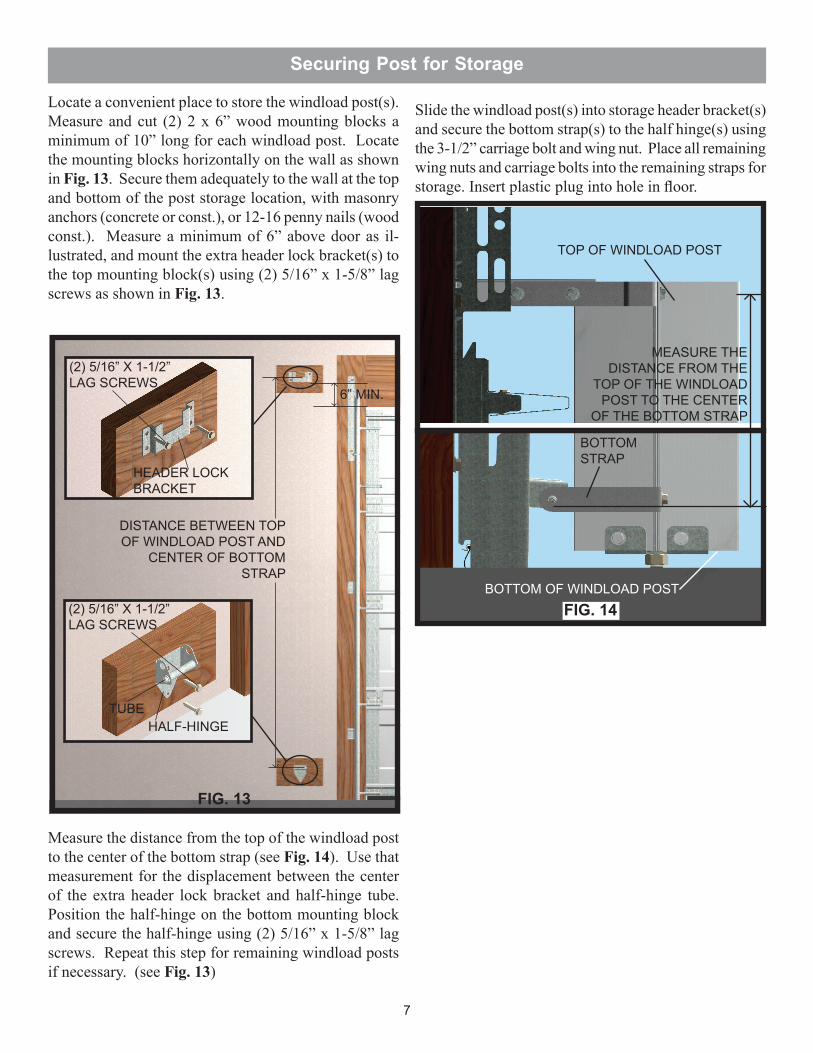
Measure the distance from the top of the windload post to the center of the bottom strap (see Fig. 14). Use that measurement for the displacement between the center of the extra header lock bracket and half-hinge tube. Position the half-hinge on the bottom mounting block and secure the half-hinge using (2) 5/16” x 1-5/8” lag screws. Repeat this step for remaining windload posts if necessary. (see Fig. 13)
Securing Post for Storage
Locate a convenient place to store the windload post(s). Measure and cut (2) 2 x 6” wood mounting blocks a minimum of 10” long for each windload post. Locate the mounting blocks horizontally on the wall as shown in Fig. 13. Secure them adequately to the wall at the top and bottom of the post storage location, with masonry anchors (concrete or const.), or 12-16 penny nails (wood const.). Measure a minimum of 6” above door as il-lustrated, and mount the extra header lock bracket(s) to the top mounting block(s) using (2) 5/16” x 1-5/8” lag screws as shown in Fig. 13.
7
Slide the windload post(s) into storage header bracket(s) and secure the bottom strap(s) to the half hinge(s) using the 3-1/2” carriage bolt and wing nut. Place all remaining wing nuts and carriage bolts into the remaining straps for storage. Insert plastic plug into hole in floor.
6” MIN.
(2) 5/16” X 1-1/2” LAG SCREWS
(2) 5/16” X 1-1/2” LAG SCREWS
HEADER LOCK BRACKET
HALF-HINGETUBE
DISTANCE BETWEEN TOP OF WINDLOAD POST AND
CENTER OF BOTTOM STRAP
MEASURE THE DISTANCE FROM THE
TOP OF THE WINDLOAD POST TO THE CENTER
OF THE BOTTOM STRAP
TOP OF WINDLOAD POST
BOTTOM OF WINDLOAD POST
BOTTOM STRAP
FIG. 13
FIG. 14

3
2
1
Attaching the Installation Decals
8
After the installation is complete, locate in a obviously visible location on the inside of the garage door and the post(s) and place the provided installation labels and tag(s) onto the door and post(s) for future reference.IMPORTANT! LABELS AND TAG(S) MUST BE ATTACHED TO BOTH DOOR AND POST(S).
Windload Label Locations
MAKE SURE LABELS AND TAG(S) LIKE THE ONES ABOVE ARE INSTALLED ON THE DOOR AND POST(S)!
CONTACT WAYNE-DALTON CORP. FOR A FREE REPLACEMENT DECAL.Please Do Not Return This Product To The Store.
Contact your local Wayne-Dalton dealer. To find your local Wayne-Dalton dealer, refer to yourlocal yellow pages/business listings or go to the Find a Dealer section online at www.wayne-dalton.com
1 Applied by Installer - One (1) Emergency High Wind Situations Tags (161384) per post -Tags are to be applied to post(s) when stored on wall for constant reminder to consumer.
2
3 Applied by Installer - One (1) Windload Post Installation Instructions Label (305213) -Only on doors specified with one or more posts. To be applied to inside of door, next to endcap of second section on side of the door where Post no. 1 is stored.
Applied by Installer - One (1) Windload PSF Label per post, based on the required design PSF load. Label is to be applied to windload post for reference.