Wind Turbine Generator System General Specification for · PDF fileHQ 1650 Wind Turbine...
14
HQ 1650 Wind Turbine Generator System General Specification for HQ1650 3 Dec 2010 Hyundai Heavy Industries Co., Ltd Electro Electric Systems http://www.hyundai-elec.co.kr
Transcript of Wind Turbine Generator System General Specification for · PDF fileHQ 1650 Wind Turbine...

HQ 1650
Wind Turbine Generator System
General Specification for
HQ1650
3 Dec 2010
Hyundai Heavy Industries Co., Ltd Electro Electric Systems
h t t p : / / w w w. h y u n d a i - e l e c . c o . k r
HQ 1650
http://www.hyundai-elec.co.kr Page 2 of 14 3/Dec/2010
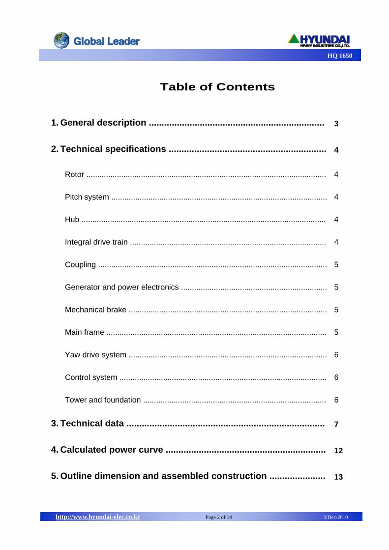
Table of Contents
1. General description ..................................................................... 3
2. Technical specifications .............................................................. 4
Rotor .............................................................................................................. 4
Pitch system ................................................................................................... 4
Hub ................................................................................................................ 4
Integral drive train .......................................................................................... 4
Coupling ......................................................................................................... 5
Generator and power electronics ................................................................... 5
Mechanical brake ........................................................................................... 5
Main frame ..................................................................................................... 5
Yaw drive system ........................................................................................... 6
Control system ............................................................................................... 6
Tower and foundation .................................................................................... 6
3. Technical data .............................................................................. 7
4. Calculated power curve ............................................................... 12
5. Outline dimension and assembled construction ...................... 13
HQ 1650
http://www.hyundai-elec.co.kr Page 3 of 14 3/Dec/2010
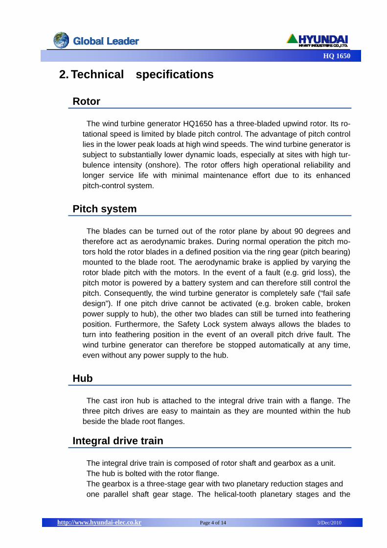
1. General description
The HQ1650 is a pitch regulated upwind wind turbine with active yaw and a
three-blade rotor.
The HQ1650 has a rotor diameter of 77m with a generator rated at 1.65MW.
With these feathered rated power will be maintained even in high wind speeds,
regardless of air temperature and air density, and the wind turbine is able to
operate the rotor at variable speed. And variable speed ensures a steady
electric power production from the turbine. The variable speed system con-
sists of a doubly fed induction generator with wound rotor, slip rings and
power converter. A power converter is connected to the rotor to control the
generator at variable speed.
Overview
HQ 1650
http://www.hyundai-elec.co.kr Page 4 of 14 3/Dec/2010
2. Technical specifications
Rotor The wind turbine generator HQ1650 has a three-bladed upwind rotor. Its ro-
tational speed is limited by blade pitch control. The advantage of pitch control lies in the lower peak loads at high wind speeds. The wind turbine generator is subject to substantially lower dynamic loads, especially at sites with high tur-bulence intensity (onshore). The rotor offers high operational reliability and longer service life with minimal maintenance effort due to its enhanced pitch-control system.
Pitch system The blades can be turned out of the rotor plane by about 90 degrees and
therefore act as aerodynamic brakes. During normal operation the pitch mo-tors hold the rotor blades in a defined position via the ring gear (pitch bearing) mounted to the blade root. The aerodynamic brake is applied by varying the rotor blade pitch with the motors. In the event of a fault (e.g. grid loss), the pitch motor is powered by a battery system and can therefore still control the pitch. Consequently, the wind turbine generator is completely safe (“fail safe design”). If one pitch drive cannot be activated (e.g. broken cable, broken power supply to hub), the other two blades can still be turned into feathering position. Furthermore, the Safety Lock system always allows the blades to turn into feathering position in the event of an overall pitch drive fault. The wind turbine generator can therefore be stopped automatically at any time, even without any power supply to the hub.
Hub The cast iron hub is attached to the integral drive train with a flange. The
three pitch drives are easy to maintain as they are mounted within the hub beside the blade root flanges.
Integral drive train The integral drive train is composed of rotor shaft and gearbox as a unit. The hub is bolted with the rotor flange. The gearbox is a three-stage gear with two planetary reduction stages and one parallel shaft gear stage. The helical-tooth planetary stages and the
HQ 1650
http://www.hyundai-elec.co.kr Page 5 of 14 3/Dec/2010
helical-tooth parallel-shaft stage are optimized with shape and tooth trace compensation. To compensate for internal loads, the planetary stage sun wheels are self adjusting. The gearbox is forced lubricated. The gear oil temperature is monitored by a
sensor and automatically cooled by a separate oil-air cooler and a filter unit in the nacelle if the permissible oil temperature is exceeded. Mechanical seals ensure a perfect seal and are wear-resistant. The rotor controller cables are fed through the stationary hollow shaft into the
hub. A rotor lock device at the input shaft enables the drive train to be me-chanically locked for maintenance purposes.
Coupling The gearbox and the generator are linked by a flexible shaft which com-
pensates for alignment tolerances.
Generator and power electronics The wind turbine generator is equipped with a double-fed three-phase in-
duction generator. The advanced power electronics (IGBT converter) ensure that the generator works with high efficiency over the entire speed range. A heating winding is installed to prevent damage to the generator due to
damp. In addition, there are sensors to monitor the temperature in the gene-rator. The generator and the power electronics are cooled by a water-air heat exchanger.
Mechanical brake The mechanical brake is a disc brake fitted with one caliper and mounted on
the high-speed shaft of the gearbox. The hydraulic system is pressurized. To apply the brake, solenoid valves are activated and the brake pads pressed against the disc. An intelligent braking system controls the braking sequence. The brake can be released by pressurizing the hydraulic circuit.
Main frame The welded main frame transfers the loads from the integral drive train to the
yaw drive system and holds the generator and control cabinet over the bolted cantilever.
HQ 1650
http://www.hyundai-elec.co.kr Page 6 of 14 3/Dec/2010
Yaw drive system The yaw drive system consists of an external ring gear which is bolted to the
top flange of the tower plus a slide bearing. It is system is driven by four converter-fed electrical motors with a gearbox and a pinion mounted on the base plate of the main frame. Additional yaw brakes keep the wind energy converter in a fixed position until it has to be realigned with the actual wind direction. The motor brakes are released when the nacelle is turned. The yaw actuators also keep the nacelle in a fixed position, even at high eccentric wind loads.
Control system The wind turbine generator control system is based on an industrial type PLC
system. The wind turbine generator status can be checked on the display in the nacelle cabinet. The wind turbine generator control system is located in special cabinets located in the nacelle and tower base. The nacelle cabinet has the control function of pitch, yaw, generator and converter. It also controls the variants for power production by specific algorithm. The tower base cabi-net has the function of the monitoring and remote control for the nacelle cab-inet and inter-communicates the status of wind farm with SCADA system.
Tower and foundation A conical tubular steel tower with internally screwed top flange for high
maintenance safety has been designed for this wind turbine generator. Inside the tower is a ladder for accessing the nacelle, equipped with a climbing pro-tection system to prevent a fall down. The tower contains also working plat-forms at the flange connections, resting platforms in each tower section and is equipped with working and emergency lightning. The steel door at the tower base is burglar-proofed. Foundation will be designed site-specific as flat or pile foundation depending
on the soil conditions and other local requirements..
HQ 1650
http://www.hyundai-elec.co.kr Page 7 of 14 3/Dec/2010
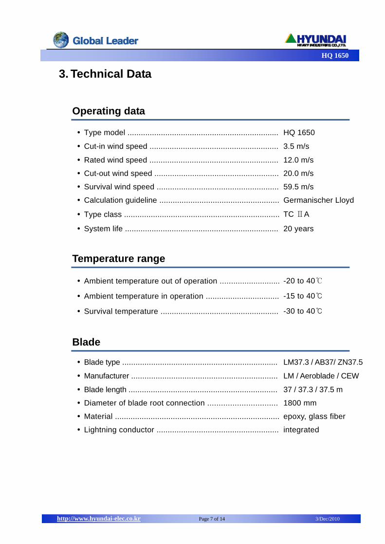
3. Technical Data
Operating data
Type model .................................................................... HQ 1650
Cut-in wind speed .......................................................... 3.5 m/s
Rated wind speed .......................................................... 12.0 m/s
Cut-out wind speed ........................................................ 20.0 m/s
Survival wind speed ....................................................... 59.5 m/s
Calculation guideline ...................................................... Germanischer Lloyd
Type class ...................................................................... TC ⅡA
System life ..................................................................... 20 years
Temperature range
Ambient temperature out of operation ........................... -20 to 40℃
Ambient temperature in operation ................................. -15 to 40℃
Survival temperature ..................................................... -30 to 40℃
Blade
Blade type ...................................................................... LM37.3 / AB37/ ZN37.5
Manufacturer .................................................................. LM / Aeroblade / CEW
Blade length ................................................................... 37 / 37.3 / 37.5 m
Diameter of blade root connection ............................... 1800 mm
Material .......................................................................... epoxy, glass fiber
Lightning conductor ....................................................... integrated

HQ 1650
http://www.hyundai-elec.co.kr Page 8 of 14 3/Dec/2010
Rotor
Number of rotor blades .................................................. 3
Rotor axis ...................................................................... horizontal
Position relative to tower ............................................... upwind
Speed range ….............................................................. 11.3 ~ 20 rpm
Rated speed .................................................................. 18.23 rpm
Direction of rotation (looking downwind) ....................... clockwise
Power control method .................................................. Pitch control
Rotor axis tilt angle ...................................................... 4.5 deg
Rotor diameter ................................................................ 77 m
Rotor area ...................................................................... 4647 / 4659 m2
Sweep angle ................................................................ 0.6 deg
Cone angle .................................................................. 0 deg
Aerodynamic brake ........................................................ full feathering
Pitch drive system
Maximum pitch control speed limit ................................... 9 deg/s
Type of pitch bearing ....................................................... 4 point ball bearing
Hub
Hub type ......................................................................... rigid
Material ........................................................................... steel iron
Mainframe
Mainframe type ............................................................... welded structure
Material .......................................................................... steel iron

HQ 1650
http://www.hyundai-elec.co.kr Page 9 of 14 3/Dec/2010
Gearbox unit
Type description ............................................................. 1st , 2nd step planetary
3rd step parallel
Transmission ratio (50/60Hz) ........................................... 1:98.74 / 1:115
Mechanical power …………………………...…….….…… 1650 kW
Bending strength ……………………………..……...…….. SF > 1.4
Surface durability …………………………..………..…….. SH > 1.0
Application factor ………………………..…………..…….. 1.3
Shaft sealing ……………………………………..…………. Labyrinth seals
Rated drive torque ........................................................... 930 kNm
Maximum static torque .................................................... 3300 kNm
Lubrication ….................................................................. oil pump
Oil capacity ..................................................................... 600 liter
Connection gear with generator ....................................... flexible coupling
Parking brake system
Type of construction ........................................................ hydraulic
Mechanical brake ............................................................ disc brake
Activation ........................................................................ passive
Convertor
Converter type ............................................................... IGBT, 4 quadrants
Rated power .................................................................. 1650 kW
Rated voltage ................................................................ 3Ф / 690 VAC
Power factor .................................................................. standard 1.0
Torque control ................................................................ field vector control

HQ 1650
http://www.hyundai-elec.co.kr Page 10 of 14 3/Dec/2010
Control system
Control device ................................................................ PLC
Remote monitoring ........................................................ yes
SCADA system .............................................................. yes
Generator
Generator type ................................................................ Double Fed Induction
Rated power ................................................................... 1650 kW
Poles .............................................................................. 4 - pole
Power factor ................................................................... 0.9
Frequency .............………………………………………….. 50/60 Hz
Stator voltage .....…………………………..…………….….. 690 VAC
Cooling ......…………………………………..………………. water cooled
Protection grade .......……………………..…………………. IP54
Yaw drive system
Type of wind direction alignment ................................... active
Type of yaw bearing ...................................................... slide bearing
Drive unit ....................................................................... planetary gear motor
Voltage …………………...…………………….……….….. 3Ф / 480/690 VAC
Number of drive units .................................................... 4
Gear ratio of yaw gear unit ...……………….……………. 1 : 1812.6
Brake ............................................................................. friction / motor brake
Nacelle cover
Type of construction ...................................................... closed
Material .......................................................................... polyester, glass fiber
HQ 1650
http://www.hyundai-elec.co.kr Page 11 of 14 3/Dec/2010
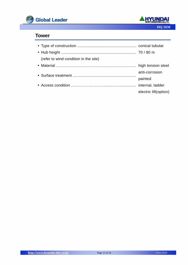
Tower
Type of construction ....................................................... conical tubular
Hub height .....................................................................
(refer to wind condition in the site)
70 / 80 m
Material ..…………………………..……………………….. high tension steel
Surface treatment .......................................................... anti-corrosion
painted
Access condition ..……………………….……….….......... internal, ladder
electric lift(option)
HQ 1650
http://www.hyundai-elec.co.kr Page 12 of 14 3/Dec/2010
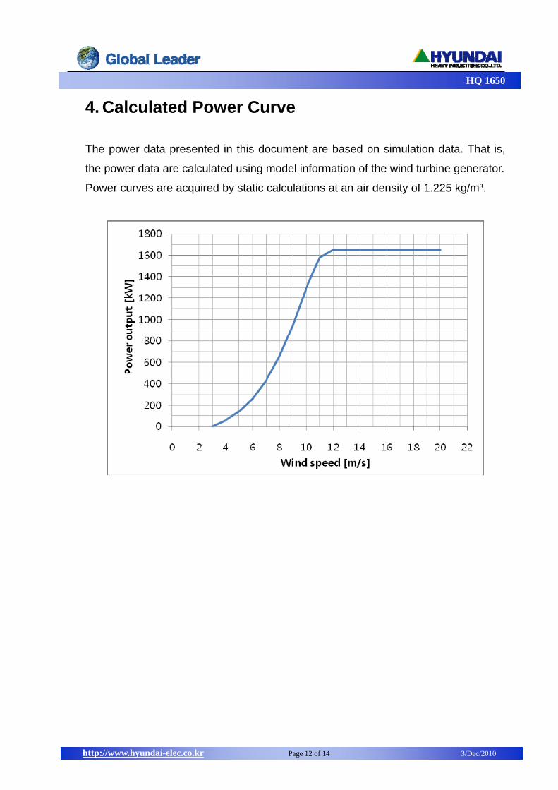
4. Calculated Power Curve
The power data presented in this document are based on simulation data. That is,
the power data are calculated using model information of the wind turbine generator.
Power curves are acquired by static calculations at an air density of 1.225 kg/m³.
HQ 1650
http://www.hyundai-elec.co.kr Page 13 of 14 3/Dec/2010
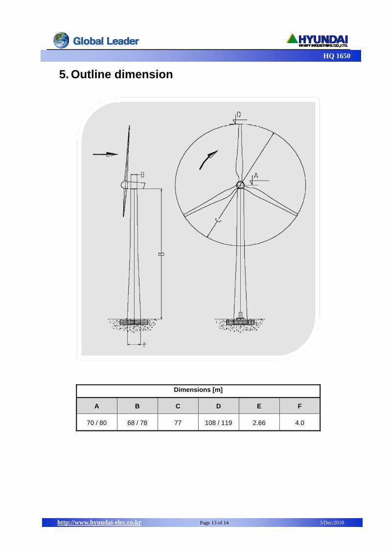
5. Outline dimension
Dimensions [m]
A B C D E F
70 / 80 68 / 78 77 108 / 119 2.66 4.0

HQ 1650
http://www.hyundai-elec.co.kr Page 14 of 14 3/Dec/2010
Assembled construction