Wind Turbine
40
A Seminar Report on WIND TURBINE Prepared by Govinder College ID: 08ELDME022 (Seminar) Under the guidance of Mr. Ajay Kumar Department of Mechanical Engineering,
-
Upload
govind-rajput -
Category
Documents
-
view
191 -
download
4
description
Seminar Report on Wind Turbine
Transcript of Wind Turbine
A Seminar Report on
WIND TURBINE
Prepared by
GovinderCollege ID:
08ELDME022 (Seminar)
Under the guidance of
Mr. Ajay Kumar
Department of Mechanical Engineering,Laxmi Devi Institute of Engineering & Technology, Chikani,
AlwarSession: 20011-12
Certificate
This is to certify that this B. Tech. Seminar Report titled Wind Turbine by Govinder is approved by me for submission. Certified further that, to the best of my knowledge, the report represents work carried out by the student.
Date: Ajay Kumar
Wind Turbine Page 2
ACKNOWLEDGEMENT
I whole heartedly express my sincere gratitude to Mr. P.M. Rastogi who guided for the preparation of my seminar report. I am also grateful to the classmates for queries to me. We are greatly benefited by this seminar presentation in terms of getting aware of Engineering at the workspace, to recognize the need for seminar, learn to become aware of the various advance technologies, to focus students on specific aspects of their studies. Therefore this presentation proved to be a blessing in disguise and it was a complete privilege for us to be a part of it.
I equally thankful to Head of Department, Department of Mechanical Engineering and other teaching and non-teaching staff for due guidance and support.
Date:
Govinder
Wind Turbine Page 3
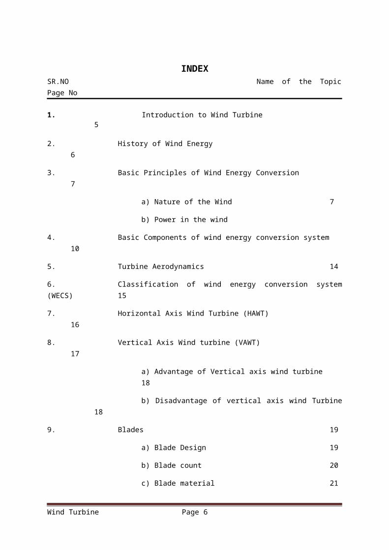
INDEXSR.NO Name of the Topic Page No
1. Introduction to Wind Turbine 5
2. History of Wind Energy 6
3. Basic Principles of Wind Energy Conversion 7
a) Nature of the Wind 7
b) Power in the wind
4. Basic Components of wind energy conversion system 10
5. Turbine Aerodynamics 14
6. Classification of wind energy conversion system (WECS) 15
7. Horizontal Axis Wind Turbine (HAWT) 16
8. Vertical Axis Wind turbine (VAWT) 17
a) Advantage of Vertical axis wind turbine 18
b) Disadvantage of vertical axis wind Turbine 18
9. Blades 19
a) Blade Design 19
b) Blade count 20
c) Blade material 21
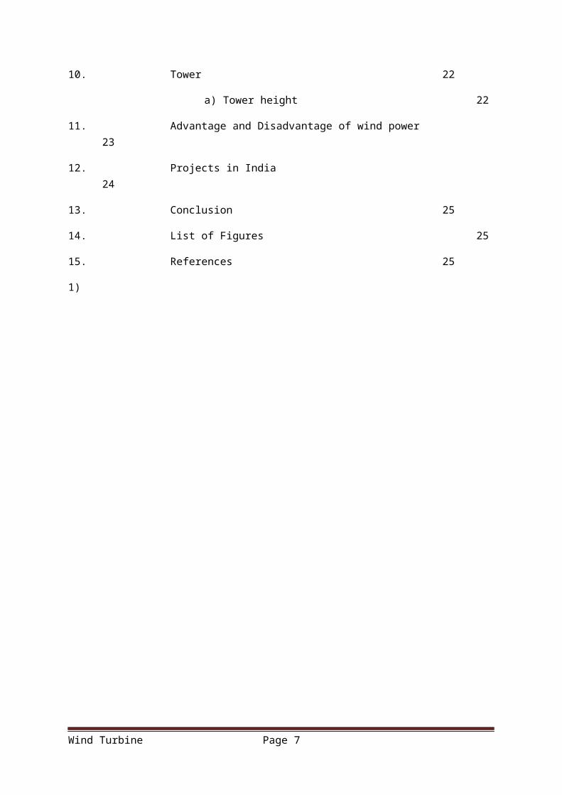
10. Tower 22
a) Tower height 22
11. Advantage and Disadvantage of wind power 23
12. Projects in India 24
13. Conclusion 25
14. List of Figures 25
15. References 25
1)
Wind Turbine Page 4
Introduction to Wind TurbineWind energy is one of the oldest source of energy used by mankind, comparable only to the use of any animal force and biomass. A wind turbine is a device that converts kinetic energy from the wind into mechanical energy. If the mechanical energy is used to produce electricity, the device may be called a wind generator or wind charger. If the mechanical energy is used to drive machinery, such as for grinding grain or pumping water, the device is called a windmill or wind pump. Developed for over a millennium, today's wind turbines are manufactured in a range of vertical and horizontal axis types. The smallest turbines are used for applications such as battery charging or auxiliary power on sailing boats; while large grid-connected arrays of turbines are becoming an increasingly large source of commercial electric power.
It's hard sometimes to imagine air as a fluid. It just seems so ... invisible. But air is a fluid like any other except that its particles are in gas form instead of liquid. And when air moves quickly, in the form of wind, those particles are moving quickly. Motion means kinetic energy, which can be captured, just like the energy in moving water can be captured by the turbine in a hydroelectric dam. In the case of a wind-electric turbine, the turbine blades are designed to capture the kinetic energy in wind. The rest is nearly identical to a hydroelectric setup: When the turbine blades capture wind energy and start moving, they spin a shaft that leads from the hub of the rotor to a generator. The generator turns that rotational energy into electricity. At its essence, generating electricity from the wind is all about transferring energy from one medium to another.
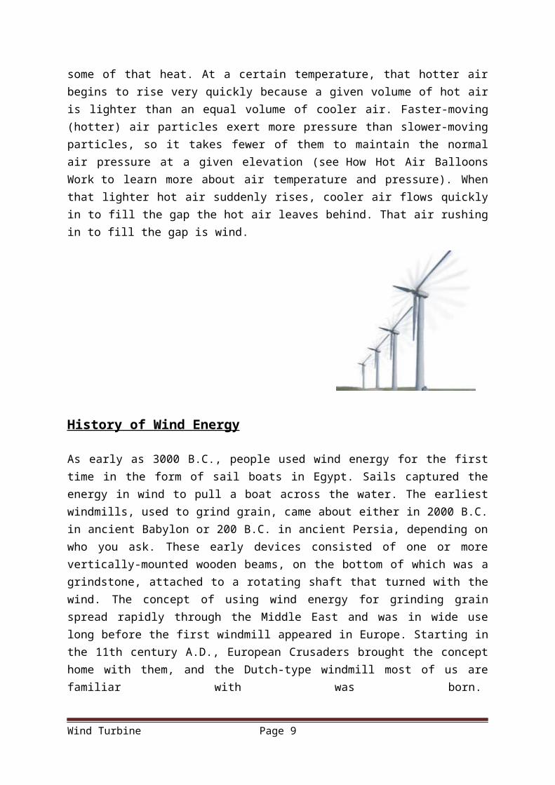
Wind power all starts with the sun. When the sun heats up a certain area of land, the air around that land mass absorbs some of that heat. At a certain temperature, that hotter air begins to rise very quickly because a given volume of hot air is lighter than an equal volume of cooler air. Faster-moving (hotter) air particles exert more pressure than slower-moving particles, so it takes fewer of them to maintain the normal air pressure at a given elevation (see How Hot Air Balloons Work to learn more about air temperature and pressure). When that lighter hot air suddenly rises, cooler air flows quickly in to fill the gap the hot air leaves behind. That air rushing in to fill the gap is wind.
Wind Turbine Page 5
History of Wind Energy
As early as 3000 B.C., people used wind energy for the first time in the form of sail boats in Egypt. Sails captured the energy in wind to pull a boat across the water. The earliest windmills, used to grind grain, came about either in 2000 B.C. in ancient Babylon or 200 B.C. in ancient Persia, depending on who you ask. These early devices consisted of one or more vertically-mounted wooden beams, on the bottom of which was a grindstone, attached to a rotating shaft that turned with the wind. The concept of using wind energy for grinding grain spread rapidly through the Middle East and was in wide use long before the first windmill appeared in Europe. Starting in the 11th century A.D., European Crusaders brought the concept home with them, and the Dutch-type windmill most of us are familiar with was born.
Modern development of wind-energy technology and applications was well underway by the 1930s, when an estimated 600,000 windmills supplied rural areas with electricity and water-pumping services. Once broad-scale electricity distribution spread to farms and country towns, use of wind energy in the United States started to subside, but it picked up again after the U.S. oil shortage in the early 1970s. Over the past 30 years, research and development has fluctuated with federal government interest and tax incentives. In the mid-'80s, wind turbines had a typical maximum power rating of 150 kW. In 2006, commercial, utility-scale turbines are commonly rated at over 1 MW and are available in up to 4 MW capacity.
Wind Turbine Page 6
Basic Principles of Wind Energy Conversion
Nature of the wind:-
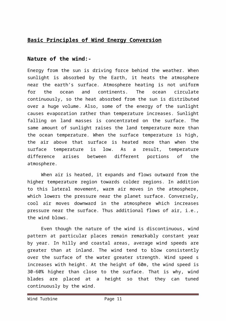
Energy from the sun is driving force behind the weather. When sunlight is absorbed by the Earth, it heats the atmosphere near the earth’s surface. Atmosphere heating is not uniform for the ocean and continents. The ocean circulate continuously, so the heat absorbed from the sun is distributed over a huge volume. Also, some of the energy of the sunlight causes evaporation rather than temperature increases. Sunlight falling on land masses is concentrated on the surface. The same amount of sunlight raises the land temperature more than the ocean temperature. When the surface temperature is high, the air above that surface is heated more than when the surface temperature is low. As a result, temperature difference arises between different portions of the atmosphere.
When air is heated, it expands and flows outward from the higher temperature region towards colder regions. In addition to this lateral movement, warm air moves in the atmosphere, which lowers the pressure near the planet surface. Conversely, cool air moves downward in the atmosphere which increases pressure near the surface. Thus additional flows of air, i.e., the wind blows.
Even though the nature of the wind is discontinuous, wind pattern at particular places remain remarkably constant year by year. In hilly and coastal areas, average wind speeds are greater than at inland. The wind tend to blow consistently over the surface of the water greater strength. Wind speed s increases with height. At the height of 60m, the wind speed is 30-60% higher than close to the surface. That is why, wind blades are placed at a height so that they can tuned continuously by the wind.
Wind Turbine Page 7

Fig1.1 (Global Circulation Of wind)
Power in the Wind :-
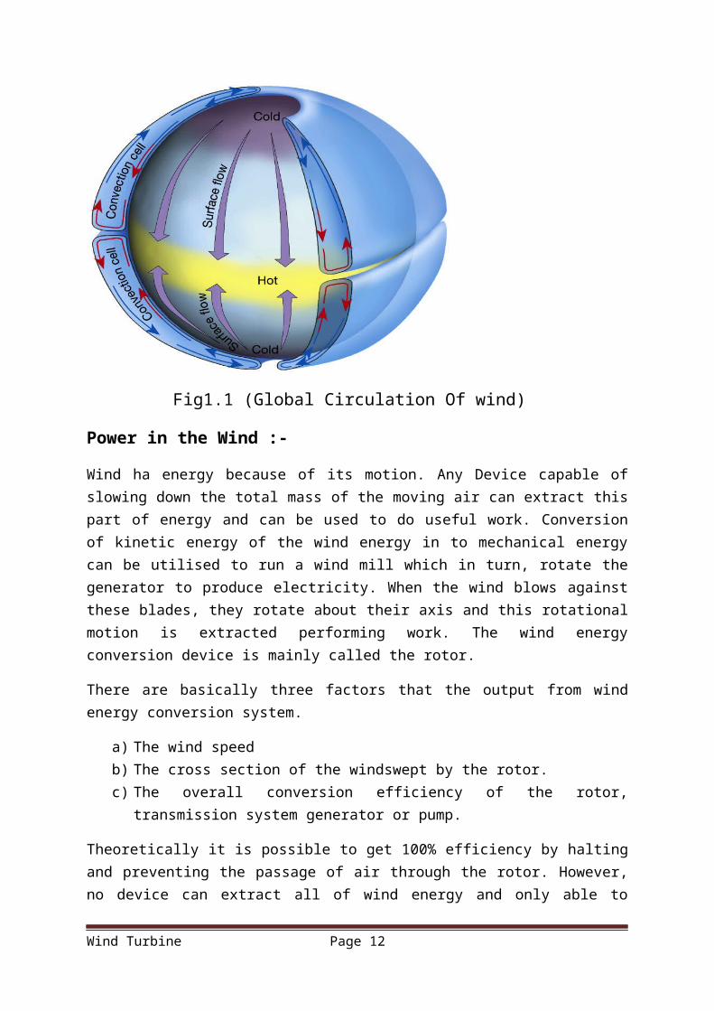
Wind ha energy because of its motion. Any Device capable of slowing down the total mass of the moving air can extract this part of energy and can be used to do useful work. Conversion of kinetic energy of the wind energy in to mechanical energy can be utilised to run a wind mill which in turn, rotate the generator to produce electricity. When the wind blows against these blades, they rotate about their axis and this rotational motion is extracted performing work. The wind energy conversion device is mainly called the rotor.
There are basically three factors that the output from wind energy conversion system.
a) The wind speedb) The cross section of the windswept by the rotor.c) The overall conversion efficiency of the rotor, transmission system generator or
pump.
Theoretically it is possible to get 100% efficiency by halting and preventing the passage of air through the rotor. However, no device can extract all of wind energy and only able to decelerate the air column to one third of its free velocity. Hence a 100% efficient wind generator is able to convert maximum up to 60% of available energy in wind into mechanical energy. In addition this, losses incurred in the generator or pump decreases the overall efficiency of power generation to 35%.
A wind mill works on the principle of converting kinetic energy of the wind to mechanical energy. Now, power is equal to energy per unit time. Energy that is available in the wind.
Kinetic energy in the particle =
We know that
Putting the value
Where ρ = air density
A = area swept by wind mill rotor
V = wind speed in m/sec
This equation tells that the power available is proportional to air density (1.225 kg/m3 at the sea level). Due to pressure and temperature change, it may vary 10-15 % during a year. Water content present in the air does not affect power in the wind. Equation also tells us that the
Wind Turbine Page 8
Power =K .E .time
=1
2(mass)×( velocity )2
time
masstime
=density×area×velocity
Power =12(density )×area×( velocity )3= ρ AV 3
2
wind turbine is proportional to the intercept area. Thus an aero turbine with a large swept area has larger power than a smaller area machine. Since area is normally circular of diameter D.
Then A=(π / 4)D2
Available wind power
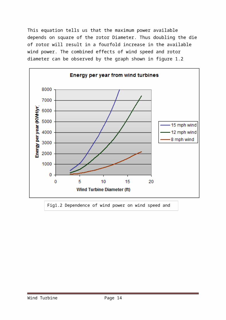
This equation tells us that the maximum power available depends on square of the rotor Diameter. Thus doubling the die of rotor will result in a fourfold increase in the available wind power. The combined effects of wind speed and rotor diameter can be observed by the graph shown in figure 1.2
Wind Turbine Page 9
P = (π/8)ρD2V3
Fig1.2 Dependence of wind power on wind speed and rotor Diameter
Basic Components of Wind Energy Conversion System (WECS)
Block diagram of components of a wind energy conversion system is shown in figure 1.3
Aero turbine are used to convert energy from moving air to rotary mechanical energy. For their proper operation they require pitch and yaw control. To transmit the rotary mechanical energy to an electrical energy, a mechanical interface consisting of a step-up gear and a suitable coupling is required. The generator output so connected to the load or power grid as the application warrants.
Yaw control: When the location of site has prevailing winds in direction most of the time, the turbine design can be greatly simplified. The rotor can be fixed in such an orientation such that the swept area is always perpendicular to the predominant wind direction .Such a machine is said to be yaw fixed. However most turbine are yaw active. When a wind changes its direction, motor rotates the turbine slowly to align along vertical axis so that blades face the wind and rotor sweep maximum area of wind stream.
In the small turbine, yaw action is controlled by a trail vane whereas in large machines a servomechanism operated by a wind direction sensor controls the yaw motor the keeps the turbine in properly oriented. The purpose of controller is to sense wind speed, wind direction, shaft speed and torque at the point so that it can control the output power and match the electrical output with wind energy input so the it can protect the system from extreme condition like cyclone and electrical faults due to strong winds.
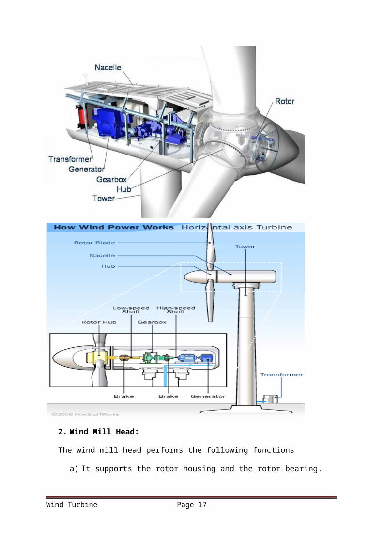
The wind-electrical generating power plant with its components is shown in figure
Wind Turbine Page 10
1. Rotors
Basically there are two types of rotor
a) Horizontal axis rotorb) Vertical axis rotor
Vertical axis machines have advantage over horizontal axis machine that they can operate in all wind direction and thus need no yaw adjustment.
Wind Turbine Page 11Fig 1.4 Wind Electric generating Power Plant
2. Wind Mill Head:
The wind mill head performs the following functions
a) It supports the rotor housing and the rotor bearing.
Wind Turbine Page 12
b) It also accommodates any control mechanism incorporated like pitch contrl mechanism, and yaw control mechanism to orient the rotor towarda wind, the the latter is mounted on the top of the supporting structure on suitable bearings
3. Transmissions.:
By varying the of the rotor blades about 40-50 revolution per minute, the rate of rotation of large wind turbine generator can be controled. For the optimum generator output it is required to have much greatre to have much greater rates of rotation, such as 1800 rpm, which can be obtained greatly increasing the low rotor rate of turning.Transmission can be done by using mechanical system involving fixed gears, belts and chains in in single or in combination or hydraulic system involving fluid pumps and motor. Because of higher efficiency ,known cost and minimum system risk fixed ratio gears are recommended for top mounted equipment. For bottomequpment,transmission cost are redused substantially by using large diameter bearing with ring gear placed on the hub to serve as a transmission to increase rotor speed to generator speed. Such a combination provides a high degree of design flexibilty as well as potential savings.
3. Generator:
At its most basic, a generator is a pretty simple device. It uses the properties of electromagnetic induction to produce electrical voltage - a difference in electrical charge. Voltage is essentially electrical pressure - it is the force that moves electricity, or electrical current, from one point to another. So generating voltage is in effect generating current. A simple generator consists of magnets and a conductor. The conductor is typically a coiled wire. Inside the generator, the shaft connects to an assembly of permanent magnets that surrounds the coil of wire. In electromagnetic induction, if you have a conductor surrounded by magnets, and one of those parts is rotating relative to the other, it induces voltage in the conductor. When the rotor spins the shaft, the shaft spins the assembly of magnets, generating voltage in the coil of wire. That voltage drives electrical current (typically alternating current, or AC power) out through power lines for distribution.
4. Controls:
It perform following functions:
a) Yaw control by orientaion the rotor in the direction of the wind.
Wind Turbine Page 13
b) Pitch control of the blades to produce required power.c) Power generator output monitoring by data computing and data storage.d) Maintenance mode.e) Emergency Power.f) Emergency shutdown control owing to malfuction or very high winds.g) Start-up and out-in of the equipment.
Control system have many combination possible and may involve the following components:
i. Sensor- mechanical,electrical or pneumatic;ii. Decision elements- relays, logic gates, analog circuits, microprocessors or a
mechanical unit.iii. Actuators- hydraulic, pnuematic or electric
.5. Towers
Four types of supprting tower can be considered for use:
a) The pole towerb) The reinforced concrete towerc) The truss tower andd) The built up shell-tube tower
Wind Turbine Page 14

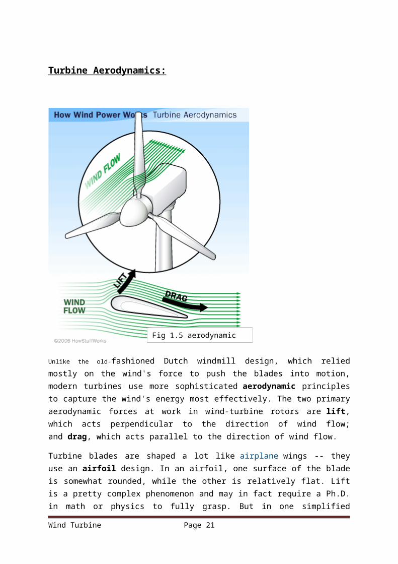
Turbine Aerodynamics:
Unlike the old-fashioned Dutch windmill design, which relied mostly on the wind's force to push the blades into motion, modern turbines use more sophisticated aerodynamic principles to capture the wind's energy most effectively. The two primary aerodynamic forces at work in wind-turbine rotors are lift, which acts perpendicular to the direction of wind flow; and drag, which acts parallel to the direction of wind flow.
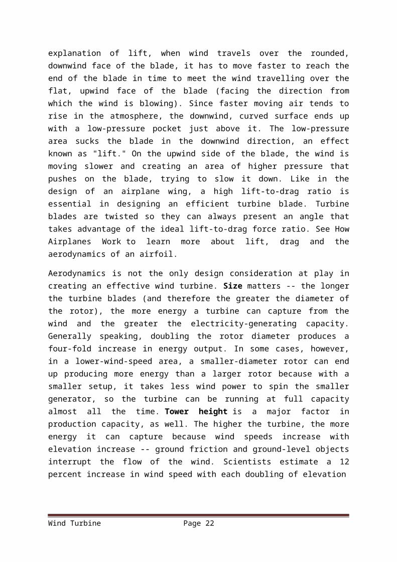
Turbine blades are shaped a lot like airplane wings -- they use an airfoil design. In an airfoil, one surface of the blade is somewhat rounded, while the other is relatively flat. Lift is a pretty complex phenomenon and may in fact require a Ph.D. in math or physics to fully grasp. But in one simplified explanation of lift, when wind travels over the rounded, downwind face of the blade, it has to move faster to reach the end of the blade in time to meet the wind travelling over the flat, upwind face of the blade (facing the direction from which the wind is blowing). Since faster moving air tends to rise in the atmosphere, the downwind, curved surface ends up with a low-pressure pocket just above it. The low-pressure area sucks the blade in the downwind direction, an effect known as "lift." On the upwind side of the blade, the wind is moving slower and creating an area of higher pressure that pushes on the blade,
Wind Turbine Page 15
Fig 1.5 aerodynamic of blades
trying to slow it down. Like in the design of an airplane wing, a high lift-to-drag ratio is essential in designing an efficient turbine blade. Turbine blades are twisted so they can always present an angle that takes advantage of the ideal lift-to-drag force ratio. See How Airplanes Work to learn more about lift, drag and the aerodynamics of an airfoil.
Aerodynamics is not the only design consideration at play in creating an effective wind turbine. Size matters -- the longer the turbine blades (and therefore the greater the diameter of the rotor), the more energy a turbine can capture from the wind and the greater the electricity-generating capacity. Generally speaking, doubling the rotor diameter produces a four-fold increase in energy output. In some cases, however, in a lower-wind-speed area, a smaller-diameter rotor can end up producing more energy than a larger rotor because with a smaller setup, it takes less wind power to spin the smaller generator, so the turbine can be running at full capacity almost all the time. Tower height is a major factor in production capacity, as well. The higher the turbine, the more energy it can capture because wind speeds increase with elevation increase -- ground friction and ground-level objects interrupt the flow of the wind. Scientists estimate a 12 percent increase in wind speed with each doubling of elevation
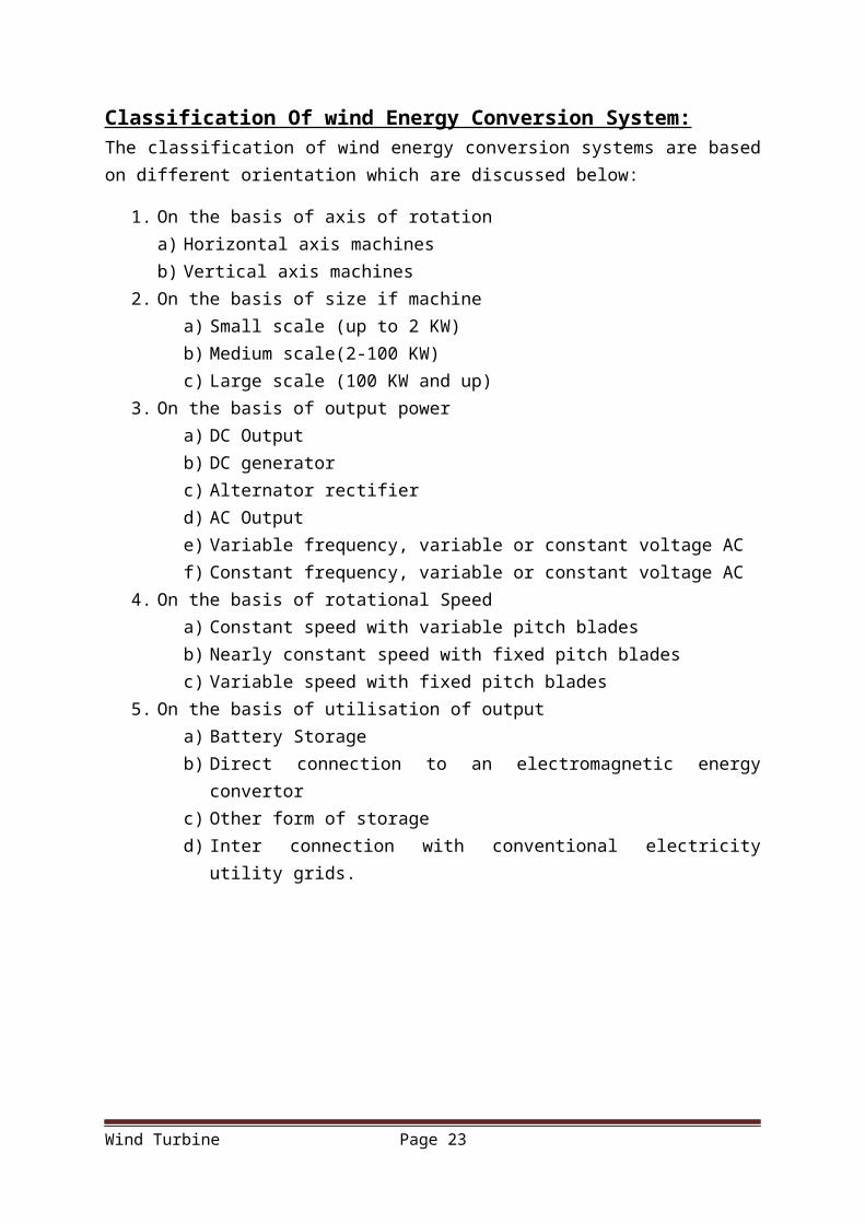
Classification Of wind Energy Conversion System:The classification of wind energy conversion systems are based on different orientation which are discussed below:
1. On the basis of axis of rotationa) Horizontal axis machinesb) Vertical axis machines
2. On the basis of size if machinea) Small scale (up to 2 KW)b) Medium scale(2-100 KW)c) Large scale (100 KW and up)
3. On the basis of output powera) DC Outputb) DC generatorc) Alternator rectifierd) AC Outpute) Variable frequency, variable or constant voltage ACf) Constant frequency, variable or constant voltage AC
4. On the basis of rotational Speeda) Constant speed with variable pitch bladesb) Nearly constant speed with fixed pitch bladesc) Variable speed with fixed pitch blades
5. On the basis of utilisation of outputa) Battery Storageb) Direct connection to an electromagnetic energy convertorc) Other form of storaged) Inter connection with conventional electricity utility grids.
Wind Turbine Page 16
Wind Turbine Page 17
Horizontal-axis wind turbine (HAWT):A wind turbine in which the axis of the rotor's rotation is parallel to the wind stream and the ground. All grid-connected commercial wind turbines today are built with a propeller-type rotor on a horizontal axis (i.e. a horizontal main shaft). Most horizontal axis turbines built today are two- or three-bladed, although some have fewer or more blades. The purpose of the rotor is to convert the linear motion of the wind into rotational energy that can be used to drive a generator. The same basic principle is used in a modern water turbine, where the flow of water is parallel to the rotational axis of the turbine blades.
The wind passes over both surfaces of the airfoil shaped blade but passes more rapidly over the longer (upper) side of the airfoil, thus creating a lower-pressure area above the airfoil. The pressure differential between top and bottom surfaces results in aerodynamic lift. In an aircraft wing, this force causes the airfoil to rise, lifting the aircraft off the ground. Since the blades of a wind turbine are constrained to move in a plane with the hub as its centre, the lift force causes rotation about the hub. In addition to the lift force, a drag force perpendicular to the lift force impedes rotor rotation. A prime objective in wind turbine design is for the blade to have a relatively high lift-to-drag ratio. This ratio can be varied along the length of the blade to optimize the turbine's energy output at various wind speeds.
These may be single bladed, double bladed and multi bladed.
Most common design is the three-bladed turbine. The most important reason is the stability of the turbine. A rotor with an odd number of rotor blades (and at least three blades) can be considered to be similar to a disc when calculating the dynamic properties of the machine.
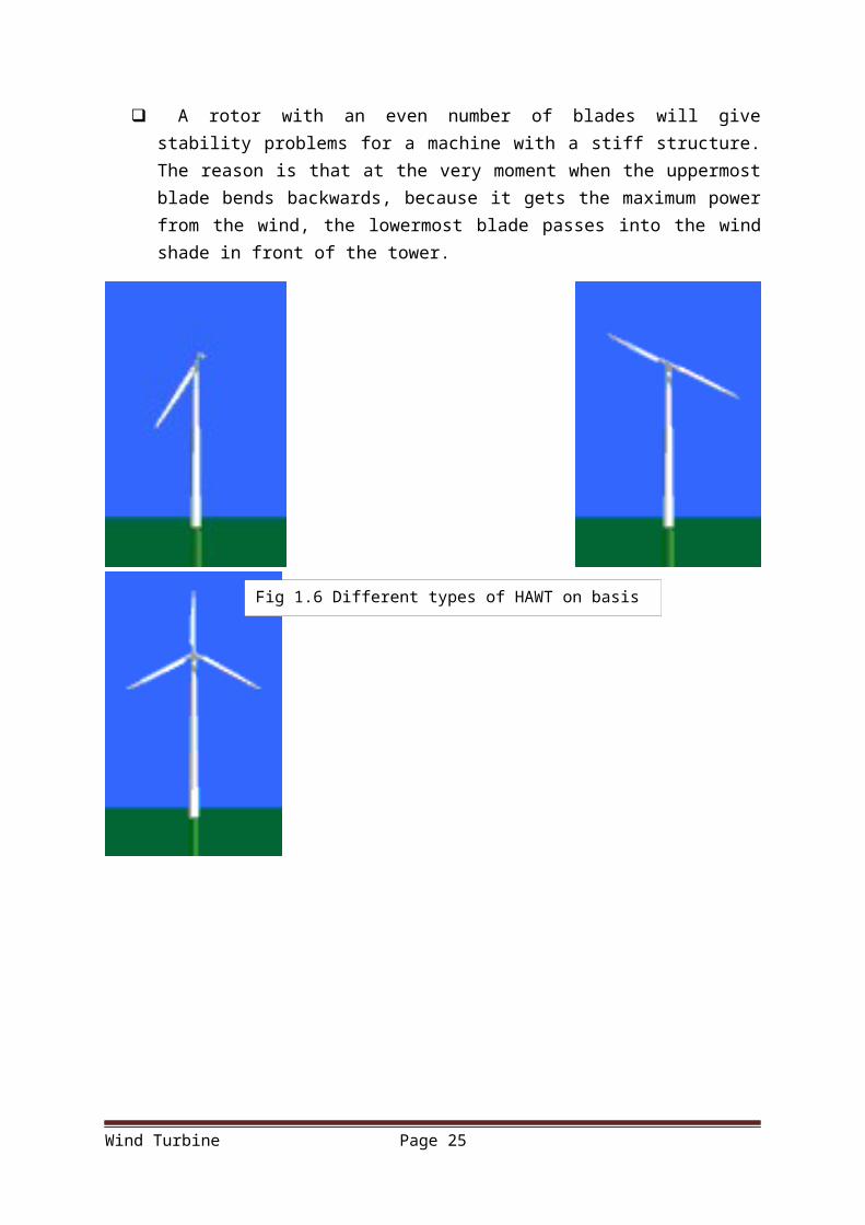
A rotor with an even number of blades will give stability problems for a machine with a stiff structure. The reason is that at the very moment when the uppermost blade bends backwards, because it gets the maximum power from the wind, the lowermost blade passes into the wind shade in front of the tower.
Wind Turbine Page 18Fig 1.6 Different types of HAWT on basis of no. of blades
Wind Turbine Page 19
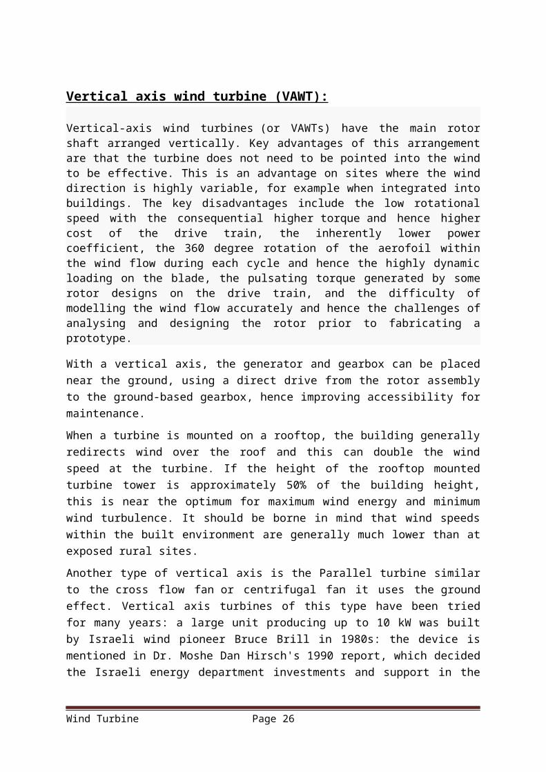
Vertical axis wind turbine (VAWT):
Vertical-axis wind turbines (or VAWTs) have the main rotor shaft arranged vertically. Key advantages of this arrangement are that the turbine does not need to be pointed into the wind to be effective. This is an advantage on sites where the wind direction is highly variable, for example when integrated into buildings. The key disadvantages include the low rotational speed with the consequential higher torque and hence higher cost of the drive train, the inherently lower power coefficient, the 360 degree rotation of the aerofoil within the wind flow during each cycle and hence the highly dynamic loading on the blade, the pulsating torque generated by some rotor designs on the drive train, and the difficulty of modelling the wind flow accurately and hence the challenges of analysing and designing the rotor prior to fabricating a prototype.
With a vertical axis, the generator and gearbox can be placed near the ground, using a direct
drive from the rotor assembly to the ground-based gearbox, hence improving accessibility for
maintenance.
When a turbine is mounted on a rooftop, the building generally redirects wind over the roof
and this can double the wind speed at the turbine. If the height of the rooftop mounted turbine
tower is approximately 50% of the building height, this is near the optimum for maximum
wind energy and minimum wind turbulence. It should be borne in mind that wind speeds
within the built environment are generally much lower than at exposed rural sites.
Another type of vertical axis is the Parallel turbine similar to the cross flow fan or centrifugal
fan it uses the ground effect. Vertical axis turbines of this type have been tried for many
years: a large unit producing up to 10 kW was built by Israeli wind pioneer Bruce Brill in
1980s: the device is mentioned in Dr. Moshe Dan Hirsch's 1990 report, which decided the
Israeli energy department investments and support in the next 20 years. The Magenn Wind
Kite blimp uses this configuration as well, chosen because of the ease of running.
Subtypes of the vertical axis design include:
a) Darrieus wind turbineb) Savonius wind turbine
Wind Turbine Page 20
(a) (b)
Advantages of vertical axis wind turbine
VAWTs offer a number of advantages over traditional horizontal-axis wind
turbines (HAWTs). They can be packed closer together in wind farms, allowing more in a
given space. This is not because they are smaller, but rather due to the slowing effect on the
air that HAWTs have, forcing designers to separate them by ten times their width.
VAWTs are rugged, quiet, omni-directional, and they do not create as much stress on the
support structure. They do not require as much wind to generate power, thus allowing them to
be closer to the ground. By being closer to the ground they are easily maintained and can be
installed on chimneys and similar tall structures.
Disadvantages of vertical axis wind turbine
Some disadvantages that the VAWTs possess are that they have a tendency to stall under
gusty winds. VAWTs have very low starting torque, as well as dynamic stability problems.
The VAWTs are sensitive to off-design conditions and have a low installation height limiting
to operation to lower wind speed environments.
The blades of a VAWT are prone to fatigue as the blade spins around the central axis. The
vertically oriented blades used in early models twisted and bent as they rotated in the wind.
This caused the blades to flex and crack. Over time the blades broke apart and sometimes
leading to catastrophic failure. Because of these problem, Vertical axis wind turbines have
proven less reliable than horizontal-axis wind turbines (HAWTs)
Wind Turbine Page 21
Fig 1.7 Darrieus and Savonius Wind Turbine
Blades:Blade design:-
The ratio between the speed of the blade tips and the speed of the wind is called tip speed
ratio. High efficiency 3-blade-turbines have tip speed/wind speed ratios of 6 to 7. Modern
wind turbines are designed to spin at varying speeds (a consequence of their generator design,
see above). Use of aluminium and composite materials in their blades has contributed to
low rotational inertia, which means that newer wind turbines can accelerate quickly if the
winds pick up, keeping the tip speed ratio more nearly constant. Operating closer to their
optimal tip speed ratio during energetic gusts of wind allows wind turbines to improve energy
capture from sudden gusts that are typical in urban settings.
In contrast, older style wind turbines were designed with heavier steel blades, which have
higher inertia, and rotated at speeds governed by the AC frequency of the power lines. The
high inertia buffered the changes in rotation speed and thus made power output more stable.
The speed and torque at which a wind turbine rotates must be controlled for several reasons:
To optimize the aerodynamic efficiency of the rotor in light winds.
To keep the generator within its speed and torque limits.
To keep the rotor and hub within their centrifugal force limits. The centrifugal force from
the spinning rotors increases as the square of the rotation speed, which makes this
structure sensitive to over speed.
To keep the rotor and tower within their strength limits. Because the power of the wind
increases as the cube of the wind speed, turbines have to be built to survive much higher
wind loads (such as gusts of wind) than those from which they can practically generate
power. Since the blades generate more torsional and vertical forces (putting far greater
stress on the tower and nacelle due to the tendency of the rotor to precess and nutate)
when they are producing torque, most wind turbines have ways of reducing torque in
high winds.
To enable maintenance. Since it is dangerous to have people working on a wind turbine
while it is active, it is sometimes necessary to bring a turbine to a full stop.
To reduce noise. As a rule of thumb, the noise from a wind turbine increases with the
fifth power of the relative wind speed (as seen from the moving tip of the blades). In
noise-sensitive environments, the tip speed can be limited to approximately 60 m/s
(200 ft/s).
It is generally understood that noise increases with higher blade tip speeds. To increase tip
speed without increasing noise would allow reduction the torque into the gearbox and
Wind Turbine Page 22
generator and reduce overall structural loads, thereby reducing cost. The reduction of noise is
linked to the detailed aerodynamics of the blades, that reduce abrupt stalling.
Blade count:-
The determination of the number of blades involves design considerations of aerodynamic
efficiency, component costs, system reliability, and anaesthetics. Noise emissions are affected
by the location of the blades upwind or downwind of the tower and the speed of the rotor.
Given that the noise emissions from the blades' trailing edges and tips vary by the 5th power
of blade speed, a small increase in tip speed can make a large difference.
Wind turbines developed over the last 50 years have almost universally used either two or
three blades. Aerodynamic efficiency increases with number of blades but with diminishing
return. Increasing the number of blades from one to two yields a six percent increase in
aerodynamic efficiency, whereas increasing the blade count from two to three yields only an
additional three percent in efficiency. Further increasing the blade count yields minimal
improvements in aerodynamic efficiency and sacrifices too much in blade stiffness as the
blades become thinner.
Component costs that are affected by blade count are primarily for materials and
manufacturing of the turbine rotor and drive train. Generally, the fewer the number of blades,
the lower the material and manufacturing costs will be. In addition, the fewer the number of
blades, the higher the rotational speed can be. This is because blade stiffness requirements to
avoid interference with the tower limit how thin the blades can be manufactured, but only for
upwind machines; deflection of blades in a downwind machine results in increased tower
clearance. Fewer blades with higher rotational speeds reduce peak torques in the drive train,
resulting in lower gearbox and generator costs.
System reliability is affected by blade count primarily through the dynamic loading of the
rotor into the drive train and tower systems. While aligning the wind turbine to changes in
wind direction (yawing), each blade experiences a cyclic load at its root end depending on
blade position. This is true of one, two, three blades or more. However, these cyclic loads
when combined together at the drive train shaft are symmetrically balanced for three blades,
yielding smoother operation during turbine yaw. Turbines with one or two blades can use a
pivoting teetered hub to also nearly eliminate the cyclic loads into the drive shaft and system
during yawing.
Finally, aesthetics can be considered a factor in that some people find that the three-bladed
rotor is more pleasing to look at than a one- or two-bladed rotor.
Wind Turbine Page 23
Blade materials:-
Wood and canvas sails were used on early windmills due to their low price, availability, and
ease of manufacture. Smaller blades can be made from light metals such as aluminium. These
materials, however, require frequent maintenance. Wood and canvas construction limits
the airfoilshape to a flat plate, which has a relatively high ratio of drag to force captured (low
aerodynamic efficiency) compared to solid airfoils.
Current production wind turbine blades are as large as 100 meters in diameter with prototypes
in the range of 110 to 120 meters. In 2001, an estimated 50 million kilograms
of fiberglass laminate were used in wind turbine blades.
Options also include prepreg fibreglass and vacuum-assisted resin transfer molding. Each of
these options use a glass-fiber reinforced polymer composite constructed with differing
complexity. Perhaps the largest issue with more simplistic, open-mold, wet systems are the
emissions associated with the volatile organics released. Preimpregnated materials and resin
infusion techniques avoid the release of volatiles by containing all reaction gases. However,
these contained processes have their own challenges, namely the production of thick
laminates necessary for structural components becomes more difficult. As the preform resin
permeability dictates the maximum laminate thickness, bleeding is required to eliminate
voids and insure proper resin distribution. One solution to resin distribution partially
preimpregnated fibreglass. During evacuation, the dry fabric provides a path for airflow and,
once heat and pressure are applied, resin may flow into the dry region resulting in a
thoroughly impregnated laminate structure.
Epoxy-based composites have environmental, production, and cost advantages over other
resin systems. Epoxies also allow shorter cure cycles, increased durability, and improved
surface finish. Prepreg operations further reduce processing time over wet lay-up systems. As
turbine blades pass 60 meters, infusion techniques become more prevalent; the traditional
resin transfer moulding injection time is too long as compared to the resin set-up time,
limiting laminate thickness. Injection forces resin through a thicker ply stack, thus depositing
the resin where in the laminate structure before gelatine occurs.
Carbon fibre-reinforced load-bearing spars can reduce weight and increase stiffness. Using
carbon fibres in 60 meter turbine blades is estimated to reduce total blade mass by 38% and
decrease cost by 14% compared to 100% fibreglass. Carbon fibres have the added benefit of
reducing the thickness of fibreglass laminate sections.
Wind Turbine Page 24
TowerTypically, 2 types of towers exist: floating towers and land-based towers.
Tower height:
Wind velocities increase at higher altitudes due to surface aerodynamic drag (by land or water surfaces) and the viscosity of the air. The variation in velocity with altitude, called wind shear, is most dramatic near the surface.
Typically, in daytime the variation follows the wind profile power law, which predicts that wind speed rises proportionally to the seventh root of altitude. Doubling the altitude of a turbine, then, increases the expected wind speeds by 10% and the expected power by 34%. To avoid buckling, doubling the tower height generally requires doubling the diameter of the tower as well, increasing the amount of material by a factor of at least four.
At night time, or when the atmosphere becomes stable, wind speed close to the ground usually subsides whereas at turbine hub altitude it does not decrease that much or may even increase. As a result the wind speed is higher and a turbine will produce more power than expected from the 1/7 power law: doubling the altitude may increase wind speed by 20% to 60%. A stable atmosphere is caused by radiative cooling of the surface and is common in a temperate climate: it usually occurs when there is a (partly) clear sky at night. When the (high altitude) wind is strong (a 10-meter (33 ft) wind speed higher than approximately 6 to 7 m/s (20–23 ft/s)) the stable atmosphere is disrupted because of friction turbulence and the atmosphere will turn neutral. A daytime atmosphere is either neutral (no net radiation; usually with strong winds and heavy clouding) or unstable (rising air because of ground heating—by the sun). Here again the 1/7 power law applies or is at least a good approximation of the wind profile. Indiana had been rated as having a wind capacity of 30,000 MW, but by raising the expected turbine height from 50 m to 70 m, the wind capacity estimate was raised to 40,000 MW, and could be double that at 100 m.
For HAWTs, tower heights approximately two to three times the blade length have been found to balance material costs of the tower against better utilisation of the more expensive active components.
Wind Turbine Page 25
Advantages of Wind Power
1. The wind blows day and night, which allows windmills to produce electricity throughout the day (Faster during the day).
2. Wind turbine take less space than average power station.
3. Up to 95 percent of land used for wind farms can also be used for agriculture purpose.
4. Wind energy is a domestic, renewable source of energy that generates no pollution and has little environmental impact.
5. We can use WT to generate electricity in remote location such as mountains and remote countryside.
Disadvantages of Wind Power 1. Not reliable , because in many areas its strength is too low to
2. Support wind turbine.
3. Sound from Wind Turbines
4. Noise pollution from commercial wind turbines is large.
5. Birds often collide with Turbine blades.
6. Wind turbine construction can be very expensive and costly to
7. surround wild Life during the build process.
8. Some birds even nest on cages on Wind Towers.
9. Present systems are neither maintenance free nor practically reliable.
Wind Turbine Page 26
Projects in IndiaIndia's Largest Wind power production facilities (10MW and greater)
Power Plant Producer Location StateTotal Capacity (MWe)
Cape ComorinAban Loyd Chiles Offshore Ltd.
Kanyakumari Tamil Nadu 33
Chennai MohanMohan Breweries & Distilleries Ltd.
Chennai Tamil Nadu 15
GudimangalamGudimangalam Wind Farm
Gudimangalam Tamil Nadu 21
Hyderabad APSRTC
Andhra Pradesh State Road Transport Corp.
HyderabadAndhra Pradesh
10
Jamgudrani MP MP Windfarms Ltd. DewasMadhya Pradesh
14
Jogmatti BSES BSES Ltd.Chitradurga Dist
Karnataka 14
Kayathar Subhash Subhash Ltd. Kayathar Tamil Nadu 30
Kethanur Wind Farm
Kethanur Wind Farm Kethanur Tamil Nadu 11
Lamda Danida Danida India Ltd. Lamda Gujarat 15
Muppandal Madras
Madras Cements Ltd. Muppandal Tamil Nadu 10
Muppandal Wind Muppandal Wind Farm Muppandal Tamil Nadu 22
Perungudi NewamNewam Power Company Ltd.
Perungudi Tamil Nadu 12
Poolavadi Chettinad
Chettinad Cement Corp. Ltd.
Poolavadi Tamil Nadu 10
Wind Turbine Page 27
Power Plant Producer Location StateTotal Capacity (MWe)
Puthlur RCI Wescare (India) Ltd. PuthlurAndhra Pradesh
20
Ramakkalmedu Subhash Ltd. Ramakkalmedu Kerala 25
Shalivahana WindShalivahana Green Energy. Ltd.
Tirupur Tamil Nadu 20.4
Vankusawade Wind Park
Suzlon Energy Ltd. Satara Dist. Maharashtra 259
Wind Turbine Page 28
Conclusion
Wind energy is also a renewable and pollution-free energy which can help us to reduce the emissions of greenhouse gases. I believe that wind energy can become an important asset to solve climate change and global warming issues in the future. It will also reduce the electricity bill for household operations.
List of Figures page no.o Fig1.1 Global Circulation Of wind
o Fig1.2 Dependence of wind power on wind speed and rotor Diameter
o fig 1.3 Block diagram of components of a wind energy conversion system
o Fig 1.4 Wind Electric generating Power Plant
o Fig 1.5 aerodynamic of blades
o Fig 1.6 Different types of HAWT on basis of no. of blades
o Fig 1.7 Darrieus and Savonius Wind Turbine
References
• http://www.bbc.co.uk/weather/
• http://www.aos.wisc.edu/~hopkins/aos100/sfc-anl.htm
• http://ww2010.atmos.uiuc.edu/(Gh)/guides/mtr/prs/hghdef.rxml
• http://en.wikipedia.org/wiki/Wind_turbine_design
• http://www.grc.nasa.gov/WWW/K-12/airplane/short.html
• A text book of Non-Conventional Energy Source (G.D. Rai) .
• http://www.howstuffworks.com/environmental/green-science/wind-power.htm l
Wind Turbine Page 29