Wind Tunnel Controller - Omega Engineering
14
omega.com e-mail: [email protected] For latest product manuals: omegamanual.info WTC-3000 Wind Tunnel Controller Shop online at User’s Guide
Transcript of Wind Tunnel Controller - Omega Engineering

omega.com e-mail: [email protected]
For latest product manuals:omegamanual.info
WTC-3000 Wind Tunnel Controller
Shop online at
User’s Guide

Servicing North America:U.S.A.: Omega Engineering, Inc., One Omega Drive, P.O. Box 4047ISO 9001 Certified Stamford, CT 06907-0047 USA
Toll Free: 1-800-826-6342 TEL: (203) 359-1660FAX: (203) 359-7700 e-mail: [email protected]
Canada: 976 BergarLaval (Quebec), Canada H7L 5A1Toll-Free: 1-800-826-6342 TEL: (514) 856-6928FAX: (514) 856-6886 e-mail: [email protected]
For immediate technical or application assistance:U.S.A. and Canada: Sales Service: 1-800-826-6342/1-800-TC-OMEGA®
Customer Service: 1-800-622-2378/1-800-622-BEST®
Engineering Service: 1-800-872-9436/1-800-USA-WHEN®
Mexico: En Español: 001 (203) 359-7803 FAX: (001) [email protected] e-mail: [email protected]
Servicing Europe:Benelux: Managed by the United Kingdom Office
Toll-Free: 0800 099 3344 TEL: +31 20 347 21 21FAX: +31 20 643 46 43 e-mail: [email protected]
Czech Republic: Frystatska 184733 01 Karviná, Czech RepublicToll-Free: 0800-1-66342 TEL: +420-59-6311899FAX: +420-59-6311114 e-mail: [email protected]
France: Managed by the United Kingdom OfficeToll-Free: 0800 466 342 TEL: +33 (0) 161 37 29 00FAX: +33 (0) 130 57 54 27 e-mail: [email protected]
Germany/Austria: Daimlerstrasse 26D-75392 Deckenpfronn, GermanyToll-Free: 0 800 6397678 TEL: +49 (0) 7059 9398-0FAX: +49 (0) 7056 9398-29 e-mail: [email protected]
United Kingdom: OMEGA Engineering Ltd.ISO 9001 Certified One Omega Drive, River Bend Technology Centre, Northbank
Irlam, Manchester M44 5BD EnglandToll-Free: 0800-488-488 TEL: +44 (0)161 777-6611FAX: +44 (0)161 777-6622 e-mail: [email protected]
OMEGAnet® Online Service Internet e-mailomega.com [email protected]
It is the policy of OMEGA Engineering, Inc. to comply with all worldwide safety and EMC/EMIregulations that apply. OMEGA is constantly pursuing certification of its products to the European NewApproach Directives. OMEGA will add the CE mark to every appropriate device upon certification.The information contained in this document is believed to be correct, but OMEGA accepts no liability for anyerrors it contains, and reserves the right to alter specifications without notice.WARNING: These products are not designed for use in, and should not be used for, human applications.

1 INTRODUCTION
1.1 Introduction
WTC-3000 is a programmable control system for automatic control of Omega wind tunnels. The
controller is connected to a PC through a USB cable for communication between the software and the
controller. The system is capable of controlling the air flow speed in the wind tunnel using a servo loop,
measuring the instantaneous temperature and velocity of the air flow.
1.2 General Applications
Heat sink manufacturers, IC houses, board designers and other electronic manufacturers are
increasingly becoming interested in evaluating the thermal performance of their product under different
airflow conditions. The reduction of electronic component sizes and increase in their power dissipation
has forced the electronic community to be more aware of the thermal performance of their products.
The hotter the devices, the shorter their life span and the greater the likelihood of a malfunction. The
general procedure for testing is to put these components in the wind tunnel and evaluate their
temperature at different flow velocities and temperatures. The operator has to wait for an average of a
half-hour for the component to reach the thermal equilibrium at each velocity. Typical characterization
requires 5 data points with an average wait time of 3 hours. The WTC-3000 automates the air flow
delivery process, thereby freeing the operator’s time.

2 HARDWARE DESCRIPTION
2.1 WTC-3000 Controller
The controller is the electronic box which accepts commands from the software through the USB
communication port and reports the data back to the system. It includes the circuitry for reading air
temperatures and velocity using a SSVP temperature sensor and a SSVP velocity sensor. Figure 1, shows
the front view of the WTC-3000 controller. The power switch on the top right hand side turns the system
on and off.
Note: Please read the manual before operating the system.
Figure 1 Front View of the WTC-3000 Controller
Figure 2 shows the rear view of the controller.
Figure 2 Rear View of the WTC-3000 Controller
The function and description of ports and connectors on the front panel are as follows:
1. POWER - Main AC power input (115V 60 Hz) to the system for powering the system.
1
2
3
4
5
6
7
8

2. PC COMM - This is the USB communication port. A special cable (provided with the system and
called COMMUNICATION CABLE is used to connect the WTC-3000 system to a PC. All
communication between the WTC-3000 and software is through this port.
3. FAN POS - This is the positive voltage output (+24V) from the WTC-3000 which goes to the Fans.
4. FAN NEG - This is the negative voltage output from the WTC-3000 which goes to the fans.
5. PWM Output Port - This is PWM signal output from the WTC-3000 to the fans.
6. TEMP SENSOR - Temperature sensor is connected to the WTC-3000 control box through this
port. It reads the air temperature, which is used by the velocity sensor to find the air velocity in
the wind tunnel.
7. VEL SENSOR - Velocity sensor is connected to the WTC-3000 control box through this port. It
reads the air flow velocity in the wind tunnel.
8. System Cooling Fan - To keep the electronic components in the box at relatively low
temperature.
Note: If the air temperature sensor is not connected, the system will report erroneous data for
velocity.
2.2 Fan Tray
The range of air velocity is dependent on the fluid dynamic resistance of the components mounted
inside the wind tunnel. If the fan tray is attached to the WTC-3000, there is no need for any power
supply, since the WTC-3000 controller will power the fans. The fans can be powered by a 24VDC power
supply if one decides to use the wind tunnel as a stand-alone device.
NOTE: The input voltage to the fans (ebm-papst 6314/2TDHP) is rated as 16-36 volts. If the fan tray is
powered by an external power supply, please short the negative output of the external power supply
to the FAN NEG on the rear panel of the WTC-3000.
2.3 Temperature Monitoring
Omega can supply optional temperature sensors for the WTC-3000. The sensors are used for monitoring
the air temperature inside the wind tunnel. The calibration coefficients for each sensor are provided for
every unit.

2.4 Velocity Monitoring
Omega can supply optional velocity sensors for the WTC-3000. These sensors are especially calibrated
for measurement in flows ranging from 0 to 1200 ft/min (6 m/s). The sensors are used for monitoring
the air velocity at any location in the wind tunnel for controlling the blower speed and flow using a
feedback control servo loop. The calibration coefficients for each sensor are provided for every unit.
3 SOFTWARE DESCRIPTION
3.1 Operating Software
The WTC-3000 software is a graphical user interface that communicates with the controller through a PC
USB port. The software enables the user to perform an automatic flow control characterization on a test
specimen. The user can automate this process by selecting a few parameters in the software. The
temperature and velocity sensors can be attached to any surface inside the wind tunnel to control the
flow in the wind tunnel based on that point. The flow sensor uses the temperature reading obtained by
temperature sensor to calculate the velocity. In most applications the flow sensor and the thermocouple
are installed close to the entrance of the test section.
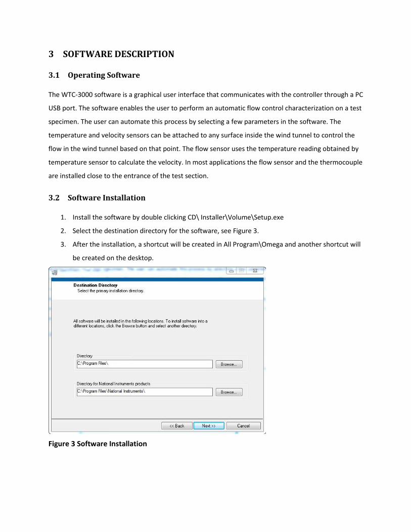
3.2 Software Installation
1. Install the software by double clicking CD\ Installer\Volume\Setup.exe
2. Select the destination directory for the software, see Figure 3.
3. After the installation, a shortcut will be created in All Program\Omega and another shortcut will
be created on the desktop.
Figure 3 Software Installation

3.3 Software Operation
When you run the software for the first time, a window (see Figure 4) will pop out asking for the
Calibration File. This file can be found on the CD sent by Omega. You have to load this file before you
can start using the software.
Figure 4 Loading Calibration File
When the software starts, it will automatically look for the WTC-3000 controller. If it cannot find the
device, a window displaying a warning will pop out, see Figure 5. Please check the USB connection
between the computer and the WTC-3000 controller. You can also check under Device Manager\Ports
(COM & LPT) to see if a USB Serial Port is present. Choose Retry or Continue to proceed.

Figure 5 “Device Not Found” Warning
The following procedures should be taken by the operator prior to starting the wind tunnel.
1. Specify the desired air velocity ranges for the experiment to be performed.
2. Select the desired number of data points. This value includes the two data points at the starting
and ending velocities. When the software is executed, the wind tunnel with begin at starting
velocity and will stay there until the dwell time is reached. The software then increases the air
velocity by the amount of velocity interval calculated from the following equation
Velocity interval = (V_Start – V_End)/(Desired number of test points –1)
3. This process is repeated for subsequent velocities until the data for the end velocity has been
obtained.
4. Set the dwell time. This is the amount of time the controller will keep the air flow velocity at the
set point.
3.4 Description of the Software User Interface
The interface of the software is illustrated in Figure 6.

Figure 6 Software User Interface
The user interface elements (number in the boxes) are explained as follows:
1. Air Velocity Chart: This chart shows the transient value and history of the air velocity.
2. Air Velocity Digital Display: This shows the current air velocity value.
3. Air Temperature Chart: This chart shows the transient value and history of the air temperature.
4. Air Temperature Digital Display: This shows the current air temperature value.
5. Wind Tunnel Model: Select the wind tunnel connected to the WTC-3000 controller. The wind
tunnel model is specified on the plate of the wind tunnel. Select the correct wind tunnel model
before starting the test.
6. Velocity Sensor Serial #: Input the velocity sensor serial #, which can be found on the sensor
connector.
7. Temperature Sensor Serial #: Input the temperature sensor serial #, which can be found on the
sensor connector.
1 3
2
7
6
4
9
10
11
12
13 14 15 16 17 18 22 20 21 23 24 19
5
8
25

8. Load New Calibration File: Click to load new calibration file for the temperature and velocity
sensors.
9. COM Port: Choose the port for data communication. The value chosen will determine which
COM port will be active for serial data communication.
10. Temperature Unit: Select the temperature unit used in the test.
11. Velocity Unit: Select the velocity unit used in the test.
12. Save Data: Check the box to save the temperature and velocity data.
13. File Path: Enter a file path for the test data.
14. Air velocity _Start: Set the starting velocity.
15. Air velocity _End: Set the ending velocity.
16. Dwell time. This is the amount of time, in minutes, spent between each velocity interval.
17. Number of Test Points: Enter the desired number of data points. For example, if you enter 6, the
software will perform the experiment for six different velocities, i.e. at the starting and ending
velocities and four velocities in between at equal velocity intervals.
18. Start/Stop: When Start is pressed, the software turns on the fans and testing begins. When Stop
is pressed, testing ends and the software asks if you would like to turn the fans off.
19. Air Velocity: Air velocity indicator.
20. Target Velocity: This shows the target velocity.
21. V Output (V): This shows the output of the velocity sensor. This value is for debug purposes only.
22. Air Temperature: Air temperature indicator.
23. Elapsed Time: This shows the elapsed time, in minutes, at the current test point.
24. T Output (Ohm): This shows the output of the temperature sensor. This value is for debug
purposes only.
25. System Status: This displays the system’s operating status.

Figure 7 Sensor Serial # Warning
Note: If the Temperature/Velocity Sensor Serial # is incorrect, a warning window will pop out when
the test starts, see Figure 7. Please select “Return” and input the correct serial number.

WARRANTY/DISCLAIMEROMEGA ENGINEERING, INC. warrants this unit to be free of defects in materials and workmanship for aperiod of 13 months from date of purchase. OMEGA’s WARRANTY adds an additional one (1) monthgrace period to the normal one (1) year product warranty to cover handling and shipping time. Thisensures that OMEGA’s customers receive maximum coverage on each product. If the unit malfunctions, it must be returned to the factory for evaluation. OMEGA’s Customer ServiceDepartment will issue an Authorized Return (AR) number immediately upon phone or written request.Upon examination by OMEGA, if the unit is found to be defective, it will be repaired or replaced at nocharge. OMEGA’s WARRANTY does not apply to defects resulting from any action of the purchaser,including but not limited to mishandling, improper interfacing, operation outside of design limits, improper repair, or unauthorized modification. This WARRANTY is VOID if the unit shows evidence of having been tampered with or shows evidence of having been damaged as a result of excessive corrosion;or current, heat, moisture or vibration; improper specification; misapplication; misuse or other operatingconditions outside of OMEGA’s control. Components in which wear is not warranted, include but are not limited to contact points, fuses, and triacs.OMEGA is pleased to offer suggestions on the use of its various products. However, OMEGA neither assumes responsibility for any omissions or errors nor assumes liability for anydamages that result from the use of its products in accordance with information provided byOMEGA, either verbal or written. OMEGA warrants only that the parts manufactured by thecompany will be as specified and free of defects. OMEGA MAKES NO OTHER WARRANTIES OR REPRESENTATIONS OF ANY KIND WHATSOEVER, EXPRESSED OR IMPLIED, EXCEPT THAT OFTITLE, AND ALL IMPLIED WARRANTIES INCLUDING ANY WARRANTY OF MERCHANTABILITYAND FITNESS FOR A PARTICULAR PURPOSE ARE HEREBY DISCLAIMED. LIMITATION OF LIABILITY: The remedies of purchaser set forth herein are exclusive, and the total liability of OMEGA with respect to this order, whether based on contract, warranty, negligence, indemnification, strict liability or otherwise, shall not exceed the purchase price of the component upon which liability is based. In no event shall OMEGA be liable for consequential, incidental or special damages.CONDITIONS: Equipment sold by OMEGA is not intended to be used, nor shall it be used: (1) as a “BasicComponent” under 10 CFR 21 (NRC), used in or with any nuclear installation or activity; or (2) in medicalapplications or used on humans. Should any Product(s) be used in or with any nuclear installation oractivity, medical application, used on humans, or misused in any way, OMEGA assumes no responsibilityas set forth in our basic WARRANTY/DISCLAIMER language, and, additionally, purchaser will indemnifyOMEGA and hold OMEGA harmless from any liability or damage whatsoever arising out of the use of theProduct(s) in such a manner.
RETURN REQUESTS/INQUIRIESDirect all warranty and repair requests/inquiries to the OMEGA Customer Service Department. BEFORERETURNING ANY PRODUCT(S) TO OMEGA, PURCHASER MUST OBTAIN AN AUTHORIZED RETURN(AR) NUMBER FROM OMEGA’S CUSTOMER SERVICE DEPARTMENT (IN ORDER TO AVOIDPROCESSING DELAYS). The assigned AR number should then be marked on the outside of the returnpackage and on any correspondence.The purchaser is responsible for shipping charges, freight, insurance and proper packaging to preventbreakage in transit.
FOR WARRANTY RETURNS, please have the following information available BEFORE contacting OMEGA:1. Purchase Order number under which the product
was PURCHASED,2. Model and serial number of the product under
warranty, and3. Repair instructions and/or specific problems
relative to the product.
FOR NON-WARRANTY REPAIRS, consult OMEGAfor current repair charges. Have the followinginformation available BEFORE contacting OMEGA:1. Purchase Order number to cover the COST
of the repair,2. Model and serial number of the product, and3. Repair instructions and/or specific problems
relative to the product.
OMEGA’s policy is to make running changes, not model changes, whenever an improvement is possible. This affordsour customers the latest in technology and engineering.OMEGA is a registered trademark of OMEGA ENGINEERING, INC.© Copyright 2009 OMEGA ENGINEERING, INC. All rights reserved. This document may not be copied, photocopied,reproduced, translated, or reduced to any electronic medium or machine-readable form, in whole or in part, without theprior written consent of OMEGA ENGINEERING, INC.

M-5354/0913
Where Do I Find Everything I Need for Process Measurement and Control?
OMEGA…Of Course!Shop online at omega.com SM
TEMPERATURE�� Thermocouple, RTD & Thermistor Probes, Connectors, Panels & Assemblies�� Wire: Thermocouple, RTD & Thermistor�� Calibrators & Ice Point References�� Recorders, Controllers & Process Monitors�� Infrared Pyrometers
PRESSURE, STRAIN AND FORCE�� Transducers & Strain Gages�� Load Cells & Pressure Gages�� Displacement Transducers�� Instrumentation & Accessories
FLOW/LEVEL�� Rotameters, Gas Mass Flowmeters & Flow Computers�� Air Velocity Indicators�� Turbine/Paddlewheel Systems�� Totalizers & Batch Controllers
pH/CONDUCTIVITY�� pH Electrodes, Testers & Accessories�� Benchtop/Laboratory Meters�� Controllers, Calibrators, Simulators & Pumps�� Industrial pH & Conductivity Equipment
DATA ACQUISITION�� Data Acquisition & Engineering Software�� Communications-Based Acquisition Systems�� Plug-in Cards for Apple, IBM & Compatibles�� Datalogging Systems�� Recorders, Printers & Plotters
HEATERS�� Heating Cable�� Cartridge & Strip Heaters�� Immersion & Band Heaters�� Flexible Heaters�� Laboratory Heaters
ENVIRONMENTALMONITORING AND CONTROL�� Metering & Control Instrumentation�� Refractometers�� Pumps & Tubing�� Air, Soil & Water Monitors�� Industrial Water & Wastewater Treatment�� pH, Conductivity & Dissolved Oxygen Instruments