Wind Instrument Testing Apparatus Project WITAP Team: Rob Koch Andy Lawrence.
15
Wind Instrument Testing Apparatus Project WITAP Team: Rob Koch Andy Lawrenc
-
date post
21-Dec-2015 -
Category
Documents
-
view
217 -
download
1
Transcript of Wind Instrument Testing Apparatus Project WITAP Team: Rob Koch Andy Lawrence.

Wind Instrument Testing Apparatus Project
WITAP
Team: Rob Koch Andy Lawrence

Background
•An anemometer is a device used to measure wind speed.
•Commonly it is mounted on towers or inaccessible places.
•The data generated from these devices is used to assess the feasibility of wind power generation at that site.

Problem Statement
•Vermont Technical College has an Anemometer Loan Program using NRG anemometers.
•The anemometers need to be checked periodically for function and calibration.

Type of Anemometer to be Tested:
Cup Anemometer:Simplest type of anemometerAir flow past the cups turns the spindle outputting a varying frequency signal proportional to the wind speedStandard models use a sensitive 4-pole magnetType to be calibrated in the device

Our proposed solution is to build an airflow chamber that can put out a steady and consistent air velocity to an open air anemometer and save cost.
A workshop device needs to be developed with an effective range of air flow control and data acquisition capability to assess anemometer operation and accuracy.
Solution Statement
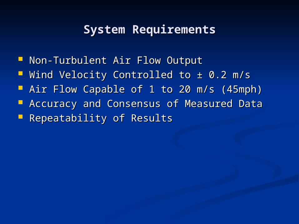
System RequirementsSystem Requirements
Non-Turbulent Air Flow OutputNon-Turbulent Air Flow Output Wind Velocity Controlled to ± 0.2 m/sWind Velocity Controlled to ± 0.2 m/s Air Flow Capable of 1 to 20 m/s (45mph)Air Flow Capable of 1 to 20 m/s (45mph) Accuracy and Consensus of Measured DataAccuracy and Consensus of Measured Data Repeatability of ResultsRepeatability of Results

Work so FarWork so Far
Design and Build Chamber Design and Build Chamber Test General Wind Flow Capability of Test General Wind Flow Capability of
SystemSystem Test Specific Airflow Characteristics of Test Specific Airflow Characteristics of
ChamberChamber Design and Build Mechanical FeaturesDesign and Build Mechanical Features Design and Build Electronic Control SystemDesign and Build Electronic Control System Test, Test, Test,Test, Test, Test,

SolutionSolution
A wind tunnel with reduced outlet for higher velocityA wind tunnel with reduced outlet for higher velocity Powered by constant-speed 120VAC fanPowered by constant-speed 120VAC fan Wind speed can be varied with shutters at inlet to fanWind speed can be varied with shutters at inlet to fan Wind speed is measured with a pitot tube connected to a Wind speed is measured with a pitot tube connected to a
pressure sensor that outputs 0 to 4V DCpressure sensor that outputs 0 to 4V DC Wind speed is controlled by using the 0 to 4 V signal and Wind speed is controlled by using the 0 to 4 V signal and
controlling the shutters accordinglycontrolling the shutters accordingly Shutter control system consists of a Motorola HC08 Shutter control system consists of a Motorola HC08
microcontroller, a Reversible DC motor controller, and a microcontroller, a Reversible DC motor controller, and a DC motor connected to the shutters. DC motor connected to the shutters.
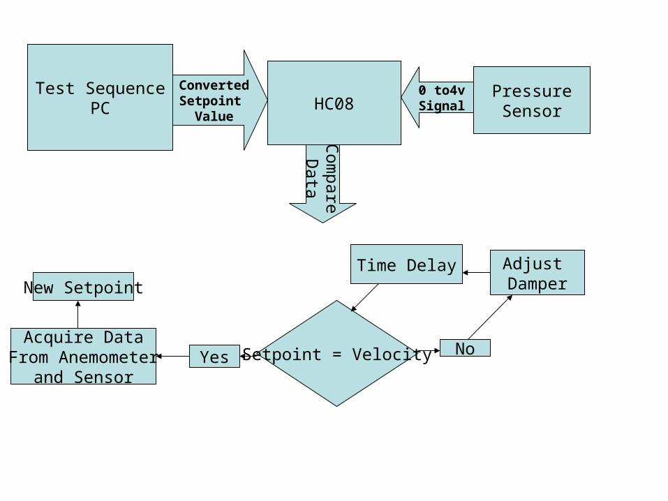
Test SequencePC HC08
PressureSensor
ConvertedSetpoint
Value
0 to4vSignal
Time Delay
Setpoint = VelocityYes NoAcquire Data
From Anemometerand Sensor
Adjust DamperNew Setpoint
Com
pareD
ata

HC08RS232
Differential Pressure
Sensor
H BridgeMotor Controller
5V GND 0.25-4V
PWM Signal
A/D
…………………….…………………….……………………
Damper Motor
+ -
Dampers
SetpointEntry
Fan
Dampers
Chamber
PC
Wind Outlet
Pitot TubeAir hoses to sensor

Outlet
υ = √2g(Pt-Ps)/γ General Equation g = acceleration of gravity, γ = specific weight of air
υ = √Pv(1.289)2 Pv (Pa), υ (m/s)υ = √Pv(4005)2 Pv (inH2O), υ (ft/min)
Pt = Total Pressure Ps = Static PressurePv = Velocity Pressure = (Pt-Ps)υ = velocity
PtPs
Measuring Air Velocity using Velocity Pressure Velocity Pressure uses the differential pressure
in the output to determine velocity
Pt tapPs tap
Manometer
Chamber
DampersFan
SimulatedWind
Air Flow
Pitot-Static Tube
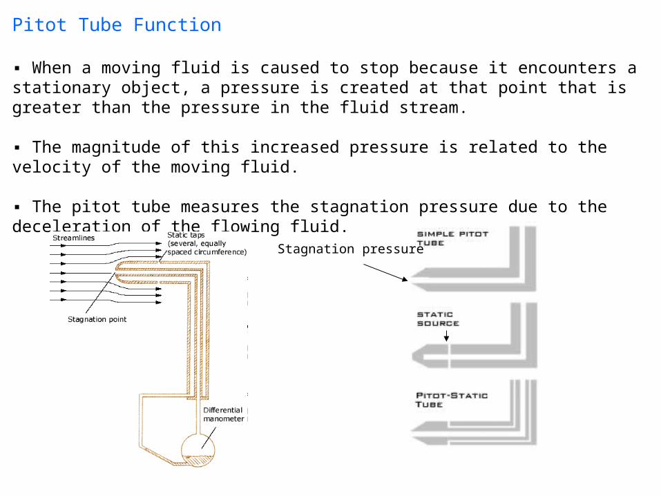
Pitot Tube Function
▪ When a moving fluid is caused to stop because it encounters a stationary object, a pressure is created at that point that is greater than the pressure in the fluid stream.
▪ The magnitude of this increased pressure is related to the velocity of the moving fluid.
▪ The pitot tube measures the stagnation pressure due to the deceleration of the flowing fluid.
Stagnation pressure

Costs
Device Needed Device Used Quantity Unit cost Balance Project CostDayton Duct Fan 4TM81 1 $813.50 $813.50 FreeMotor controller H bridge 1 $30.00 $30.00 FreeMicro controller HC08 1 $53.14 $53.14 FreeChamber MDF Box 1 $30.00 $30.00 $30.00Pressure sensor Sensirion 1 $91.21 $91.21 $91.21Manometer Dwyer 1 $64.00 $64.00 FreeManometer oil Dwyer 1 $10.08 $10.08 $10.08Pitot-static tube Dwyer 1 $48.00 $48.00 $48.00Damper Operator Denso motor 1 ? free freeDamper Unit Homebuilt 1 $20.00 $20.00 $20.00miscellaneous hardware n/a n/a n/a $10.00
$1,139.93 $179.29
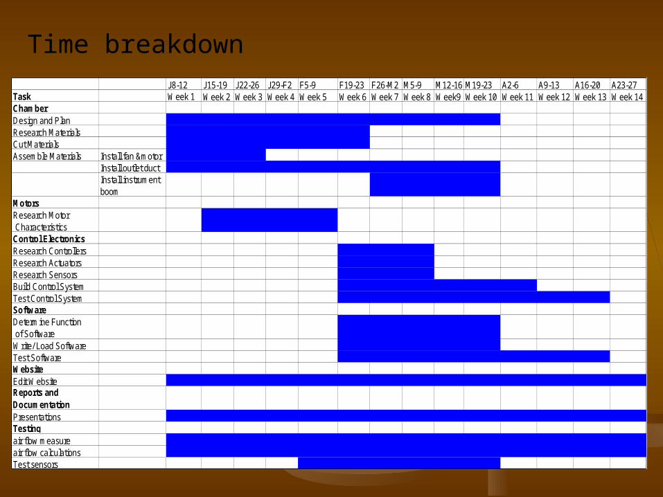
Time breakdownJ8-12 J15-19 J22-26 J29-F2 F5-9 F19-23 F26-M2 M5-9 M12-16 M19-23 A2-6 A9-13 A16-20 A23-27
Task Week 1 Week 2 Week 3 Week 4 Week 5 Week 6 Week 7 Week 8 Week9 Week 10 Week 11 Week 12 Week 13 Week 14ChamberDesign and PlanResearch MaterialsCut MaterialsAssemble Materials Install fan &motor
Install outlet ductInstall instrument boom
MotorsResearch Motor CharacteristicsControl ElectronicsResearch Controllers Research ActuatorsResearch Sensors Build Control SystemTest Control SystemSoftwareDetermine Function of SoftwareWrite/ Load SoftwareTest SoftwareWebsiteEdit WebsiteReports and DocumentationPresentationsTestingair flow measureair flow calculationsTest sensors

Questions?
![TENTH JUDICIAL DISTRICT CIVIL DEPARTMENT CHARLES G. KOCH and ) DAVID H. KOCH ... · 2012-03-01 · Koch, David Koch, and Edward Crane] to be exercised by them in the same proportions](https://static.fdocuments.in/doc/165x107/5e9c6e5451a75529cc77beaf/tenth-judicial-district-civil-department-charles-g-koch-and-david-h-koch-.jpg)