Wind Generation Representation · · 2007-07-31Wind Generation Representation WECC Modeling...
24
Wind Generation Representation WECC Modeling Efforts Abraham Ellis Public Service Company of New Mexico UWIG Annual Meeting July 2007 – Anchorage, AK
Transcript of Wind Generation Representation · · 2007-07-31Wind Generation Representation WECC Modeling...

Wind Generation RepresentationWECC Modeling Efforts
Abraham EllisPublic Service Company of New Mexico
UWIG Annual MeetingJuly 2007 – Anchorage, AK

2UWIG Annual Meeting – July 2007 – Anchorage, AK
We can’t assume… We plan!
Large-Scale Wind Power PlantsNice! But do they play nice with the Grid?
FlickerFlicker
LVRTLVRT
Frequency Frequency regulationregulation
FERCFERC
Voltage Voltage controlcontrol
RRORRO
Control Control interactioninteraction
Simulation Simulation modelsmodels
NERCNERC
StabilityStability
Contractual Contractual obligationsobligations

3UWIG Annual Meeting – July 2007 – Anchorage, AK
Wind Power Plant RepresentationGrid planner/operator perspective
Applications• Resource Planning• Power Flow / Voltage stability• Transient Stability• Short Circuit• Harmonics, control interaction• Operating impacts
Issues• Access, validation/testing, maintenance,
standards
4UWIG Annual Meeting – July 2007 – Anchorage, AK
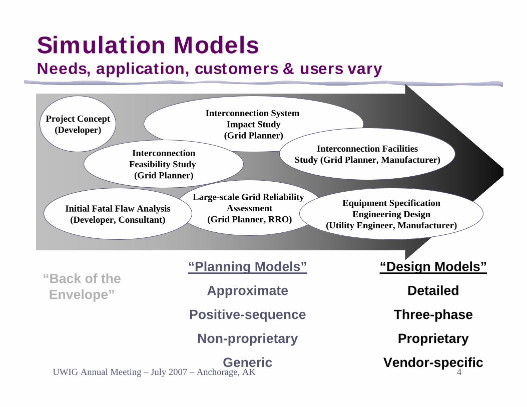
Large-scale Grid Reliability Assessment
(Grid Planner, RRO)
Simulation ModelsNeeds, application, customers & users vary
Equipment SpecificationEngineering Design
(Utility Engineer, Manufacturer)
“Design Models”
Detailed
Three-phase
Proprietary
Vendor-specific
“Planning Models”
Approximate
Positive-sequence
Non-proprietary
Generic
“Back of the Envelope”
Initial Fatal Flaw Analysis(Developer, Consultant)
Interconnection System Impact Study
(Grid Planner)
InterconnectionFeasibility Study
(Grid Planner)
Interconnection FacilitiesStudy (Grid Planner, Manufacturer)
Project Concept(Developer)

5UWIG Annual Meeting – July 2007 – Anchorage, AK
WECC Dynamic Simulation ModelsWind Generation Modeling Group (WGMG)
generator
full power
PlantFeeders
actodc
dctoac
generator
partial power
PlantFeeders
actodc
dctoac
generator
Slip poweras heat loss
PlantFeeders
PF controlcapacitor s
actodc
generator
PlantFeeders
PF controlcapacitor s
Type 1 Type 2 Type 3 Type 4
Develop standard, generic models• One model topology for each WTG “Type”, consistent
with other power system planning models• Parameters tuned for each manufacturer
Implement models in PSLF and PSSEConduct model validationRefine models

6UWIG Annual Meeting – July 2007 – Anchorage, AK
Adopted for general use in WECCApplies to Doubly-Fed Asynchronous Generators from any manufacturerStandard library model in current release versions of PSLF and PSSE programs, with full documentation• PSLF: wt3g, wt3e, wt3t, wt3p• PSSE: wt3g, wt3e, wt3t, wt3p
Model has been tested and sufficiently validated• Model validation and further model refinement will
continue
Type 3 Generic ModelSummary
Compatibility/conversion:Models are identical

7UWIG Annual Meeting – July 2007 – Anchorage, AK
Type 3 Generic ModelOverall Model Structure
Structure and level of user input similar to standard generator models• No special EPCL /
IPLAN routines• Initialize directly
from power flow• Use with standard
generator protection model

8UWIG Annual Meeting – July 2007 – Anchorage, AK
Type 3 Generic ModelGenerator/Converter Model (wt3g)

9UWIG Annual Meeting – July 2007 – Anchorage, AK
Type 3 Generic ModelConverter Control Q Control (wt3e)

10UWIG Annual Meeting – July 2007 – Anchorage, AK
Type 3 Generic ModelConverter Control P Control (wt3e)

11UWIG Annual Meeting – July 2007 – Anchorage, AK
Type 3 Generic ModelTurbine Model (wt3t)
12UWIG Annual Meeting – July 2007 – Anchorage, AK
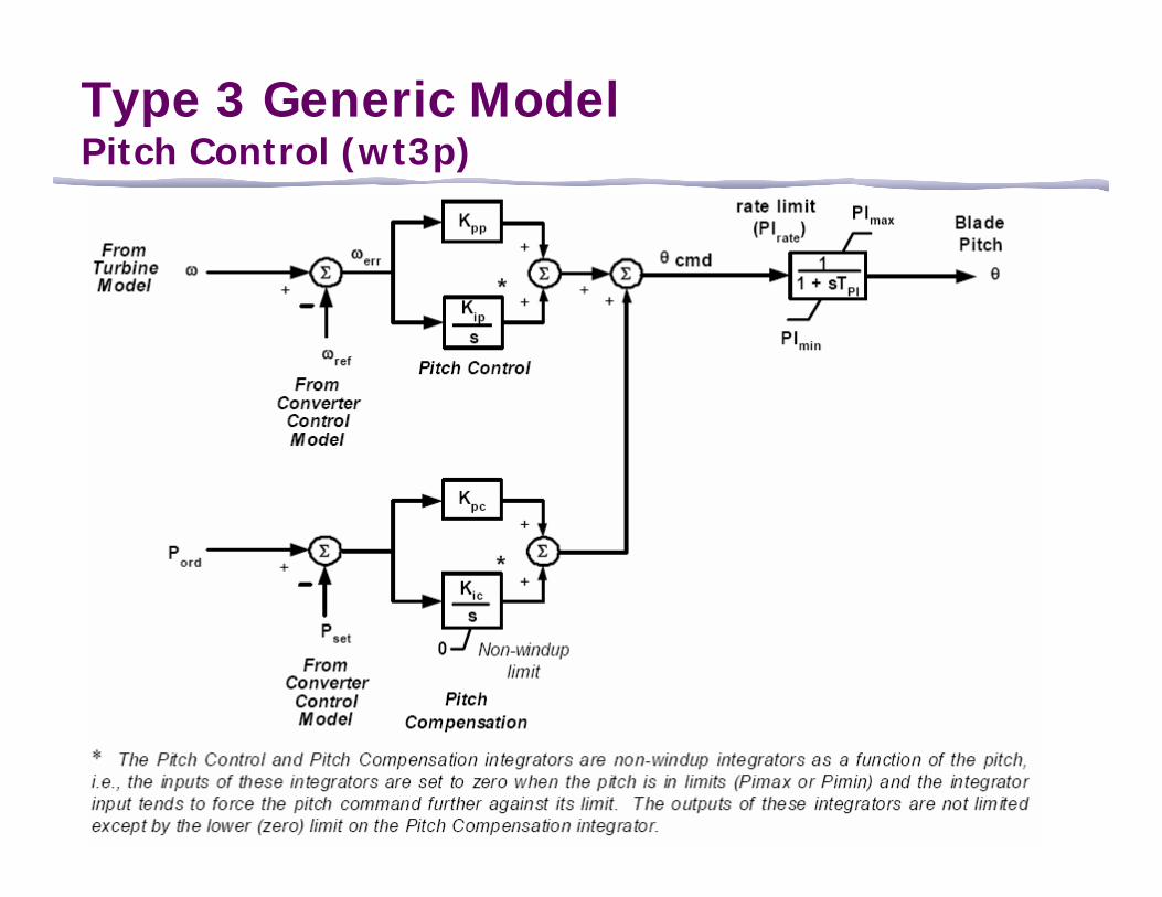
Type 3 Generic ModelPitch Control (wt3p)
13UWIG Annual Meeting – July 2007 – Anchorage, AK
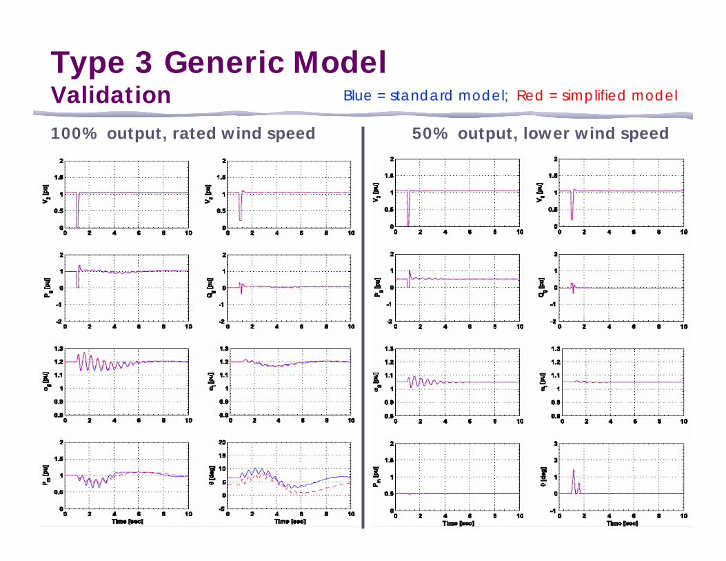
Type 3 Generic ModelValidation100% output, rated wind speed 50% output, lower wind speed
Blue = standard model; Red = simplified model

14UWIG Annual Meeting – July 2007 – Anchorage, AK
Transmission station (POI)
Equivalent WTGMain
transformer
Equivalent feeder
Equivalent pad-mounted transformer
Turbine-level power factor correction shunt capacitor, if any
POI
Plant-level reactive compensation. Could be
static and/or dynamic
Collector station with main transformer and additional reactive compensation
Feeders (overhead and/or underground)
Individual WTG, possibly with turbine-level shunt compensation
Single-Machine Equivalent Representation
NOTE: There could also be reactive compensation distributed in the collector system for voltage management
Grid
Collector station
Power Flow RepresentationSingle-machine equivalent

15UWIG Annual Meeting – July 2007 – Anchorage, AK
Assume collector system design is known for a 2-feeder, 18 WTG project…
Collector System “Equivalencing”Yields correct losses & average voltage drop

16UWIG Annual Meeting – July 2007 – Anchorage, AK
Steady-state modeling• WECC guide under development
Dynamic models• Developed initial model prototypes for each WTG Type• Type 3 model implemented in PSLF & PSSE, approved for use in
WECC• The rest of the models will be completed later this year
Validation of the models is the next major task• CEC/PIER – WECC MOU leveraged funding for wind generator model
validation project; NREL is leading technical effortIndustry collaboration will continue to be key• Model users, program developers• Manufacturers, project developers• UWIG Users Group• Working toward IEEE standard models
WECC WGMG - Progress to dateSummary

17UWIG Annual Meeting – July 2007 – Anchorage, AK
WECC VRT
MORE?

18UWIG Annual Meeting – July 2007 – Anchorage, AK
Existing WECC StandardSummary
Adopted by WECC in April, 2005Application:• All types of generators, with plant size 10 MVA or above,
interconnected at any voltage level• Withstand 3-phase faults cleared in normal time and slg
faults with delayed clearing as long asFaults are external to the power plant (system side of POI)Voltage at POI is 0.15 pu or greater
• Withstand voltage recovery defined by WECC Table W-1 as applied to a load bus
• Existing generators are exempt until the generators are replaced
Served as basis for current FERC LVRT language

19UWIG Annual Meeting – July 2007 – Anchorage, AK
WECC WGTF “VRT” White Paper(Not yet a standard!)
Objective: • Develop technical justification for developing a new Voltage Ride
Through (“VRT”) standard for the WECC• If approved, the new standard would replace the existing WECC
LVRT standard
Motivation:• Bring the WECC LVRT Standard in-line with FERC Order No. 661-
A, specifically, tolerance to zero volts for 9 cycles.• Define a boundary for the “voltage recovery” excursion that occurs
after fault clearing and before voltage returns to 90% of nominal, in which new generating plants are required to remain on-line
• Define a boundary for the “high voltage” excursion that occurs after fault clearing and before voltage returns to 110% of nominal, inwhich new generating plants are required to remain on-line

20UWIG Annual Meeting – July 2007 – Anchorage, AK
Proposed VRT StandardSee White Paper for Details
High voltage tolerance part of proposed standard
Field experience taken into account to define VRT envelope
Voltage threshold determined to be not too onerous to generators

21UWIG Annual Meeting – July 2007 – Anchorage, AK
WECC WGTF “VRT” White PaperWhat Now?
A new standard is likely to be developed based on the White Paper. Options include: • Submitting a SAR through the NERC process• Creating a WECC Regional Standard• Creating a WECC Regional Criterion
There is pressure from several sides to work on a NERC standard• VRT may fit under PRC-024 - Generator Performance
during Frequency and Voltage Excursions, which is part of the Phase III & IV standards currently under consideration
• A NERC standard could take considerable time and effort to approve because it applies to all generators

22UWIG Annual Meeting – July 2007 – Anchorage, AK
STILL MORE?
23UWIG Annual Meeting – July 2007 – Anchorage, AK
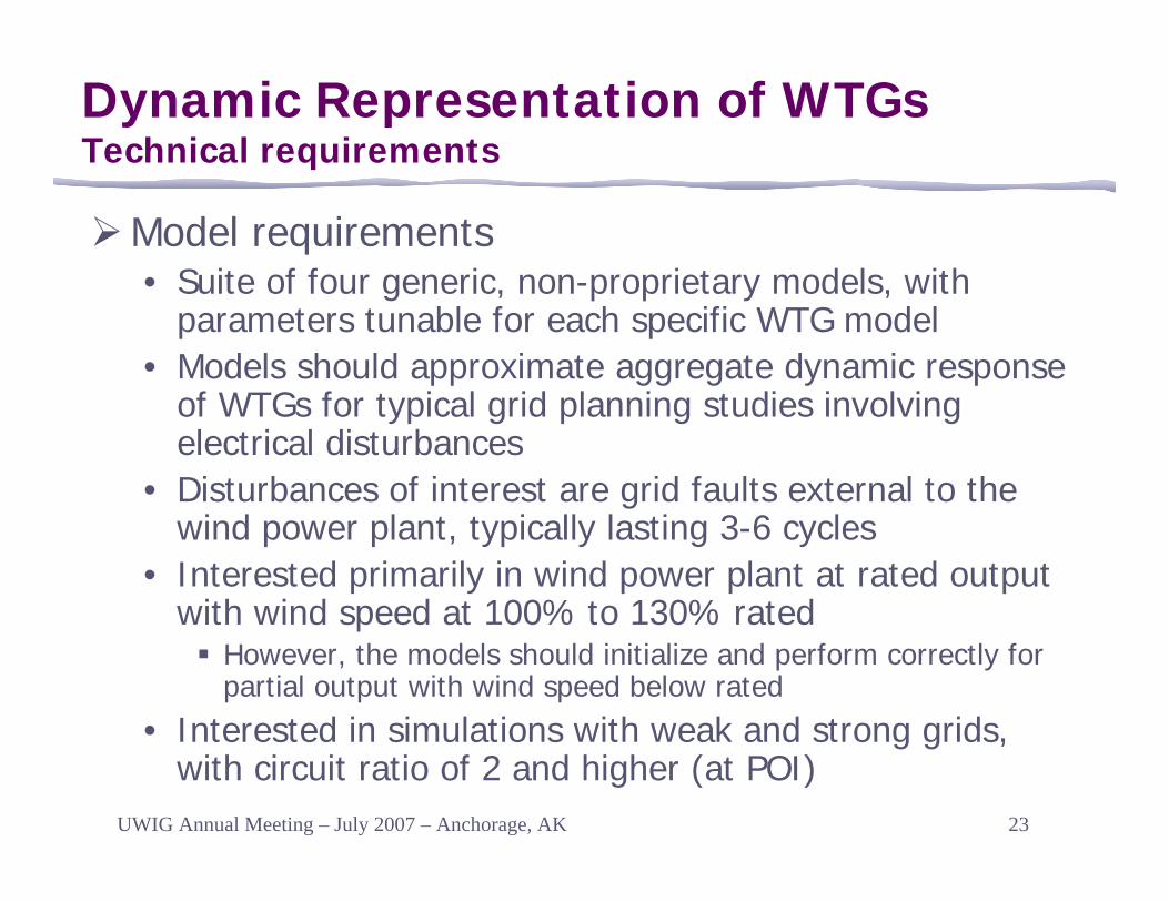
Model requirements• Suite of four generic, non-proprietary models, with
parameters tunable for each specific WTG model • Models should approximate aggregate dynamic response
of WTGs for typical grid planning studies involving electrical disturbances
• Disturbances of interest are grid faults external to the wind power plant, typically lasting 3-6 cycles
• Interested primarily in wind power plant at rated output with wind speed at 100% to 130% rated
However, the models should initialize and perform correctly for partial output with wind speed below rated
• Interested in simulations with weak and strong grids, with circuit ratio of 2 and higher (at POI)
Dynamic Representation of WTGsTechnical requirements

24UWIG Annual Meeting – July 2007 – Anchorage, AK
Model Requirements (continued)• Models should approximate actual response within a
bandwidth of DC to 6 Hz• Interested in dynamic simulations up to 30 seconds• Models should not require an integration step smaller
than 1/4 cycle• Separate, high level functional model components similar
to conventional generator models; reactive compensation modeled separately
• Include soft shaft with parameters specified in terms of total inertia, torsional frequency, and damping factor
Dynamic Representation of WTGsTechnical requirements