WIND DRIVEN WATER PUMPS Economics, Technology · PDF fileWIND DRIVEN WATER PUMPS Economics,...
27
l - /,/. 2 3 2.3 7 8 W I WIND DRIVEN WATER PUMPS Economics, Technology, Current Activities . j r ' v C i i ' « •. y<$> U ^ j n r^.- p .-,i.- :r r ."-i";i3i2-.'M;e C'oi'\..\. for r,cn;:;ixt\v ' ' ^ > " ^ •>.*•>' DECEMBER, 197B PREPARED FOR: THE WORLD BANK 1818 H STREET, N.W. WASHINGTON, D.C. U.S.A. BY: STEVE BLAKE APPROPRIATE TECHNOLOGY GROUP ROUTE 1, BOX 93-A OSKALOOSA, KANSAS 66066 U.S.A ¥, -a&23-Wi-i9^'
-
Upload
duongnguyet -
Category
Documents
-
view
222 -
download
5
Transcript of WIND DRIVEN WATER PUMPS Economics, Technology · PDF fileWIND DRIVEN WATER PUMPS Economics,...

l- / , / .
2 3 2 . 3
7 8 W I
WIND DRIVEN WATER PUMPS
Economics, Technology, Current Activities
. j r ' v C i i ' « •. y<$> U ^
jnr^.-p . - , i . - :rr ."-i";i3i2-.'M;e C'oi'\..\.
for r ,cn; : ; ix t \v ' ' ^ > " ^ •>.*•>'
DECEMBER, 197B
PREPARED FOR:
THE WORLD BANK
1818 H STREET, N.W.
WASHINGTON, D.C. U.S.A.
BY:
STEVE BLAKE
APPROPRIATE TECHNOLOGY GROUP ROUTE 1, BOX 93-A OSKALOOSA, KANSAS 66066 U.S.A
¥,
-a&23-Wi-i9^'

[I L I B R A ; , / . !.-,,-;; , -. ,-. : :" !TCn.;
I CENTRE rOU • • ., .-
I AND SA,M,-,„.:..•:, ; , , , . , / "
P.O. Box 93 LC: 2„09 AD The Haguo
Tel. (070) 8i 49 il ext. 141/142 «
Internjib.iij ^^O. -SJD CuiuA, for 0o7:i)i!\:n;;y V.'ainr S^i:!-
The Appropriate Technology Group (Route 1, Box 93-A; Oskaloosa, Kansas 66066 USA; 913-597-5603) was established in 1972 with the single goal of developing wind energy resources in developing countries. To this end, ATG has brought together researchers, engineers, and manufacturers from the United States wind energy industry to develop and improve designs, provide information, and offer consulting services. Our expertise includes both water pumping and electrical generation technologies.
©Appropriate Technology Group, 1978

CONTENTS
ANALYSIS
Overview
Characteristics
Economics
Aermotor-type
Indigenous
Gasoline Engine
Conclusions and Recommendations
Aermotor-type
Indigenous
REVIEW
Aermotor-type windmills
Aermotor
Dempster
Sparco
Indigenous windmills (horizontal axis
Polomo
SWD, Steering Committee for Wind Energy in Developing Countries
Windworks
Arusha
New Alchemy Institute
ITDG, Intermediate Technology Development Group
Savonius rotors (horizontal axis)
CIAT, Centro Internacional de Agricultura Tropical
Brace Research Institute
IRRI, International Rice Research Institute
Bibliography

1
OVERVIEW
Wind d r i v e n water pumping sys tems , w i n d m i l l s , a r e some of t h e
o l d e s t machines . P r e d a t i n g C h r i s t , windmi l l s have been developed
by many c u l t u r e s t o l i f t water for l i v e s t o c k , land d r a i n a g e ,
i r r i g a t i o n , s a l t p r o d u c t i o n , and domest ic s u p p l i e s .
The e v o l u t i o n of t h e s e v a r i o u s windmil l des igns r e f l e c t s t h e
r e s o u r c e s , economic development, s k i l l s , geography, and wa te r
needs of t h e d i f f e r e n t c u l t u r e s and r e g i o n s . These de s igns
encompass a broad spectrum of t e c h n o l o g i c a l s o p h i s t i c a t i o n .
At one end of t h i s spectrum a re t h e c e n t u r i e s o l d ind igenous
windmi l l s such as a r e s t i l l used today in t h e Medi te r ranean
r eg ion and in s o u t h e s t As ia . These d e s i g n s use many wood
components i n c l u d i n g b e a r i n g s , s a i l c l o t h and bamboo mat ' b l a d e s ' ,
and a r e f a b r i c a t e d and main ta ined l o c a l l y .
On t h e o t h e r end of t h i s spectrum a r e t h e Aermotor- type windmi l l s
developed a t t h e end of t h e 1800 ' s and a v a i l a b l e on t o d a y ' s
i n t e r n a t i o n a l expor t marke t . These windmi l l s p layed a major r o l e
in opening t h e wes tern f r o n t i e r s of North America and A u s t r a l i a ,
and a r e used e x t e n s i v e l y today in t h e s e a r e a s p r i m a r i l y for 2
w a t e r i n g l i v e s t o c k . These des igns a r e h igh ly evolved and they "
have proven h i s t o r i e s of r e l i a b i l i t y and e f f e c t i v e n e s s . cz£jT
1. For a comprehensive review of indigenous designs see "Practical Applications of Wind Powered Water Pumps" by Marcus M. Sherman; United Nations Economic and Social Commission for Asia and the Pacific, Sala Santitham, Bangkok - 2, Thailand; February, 1977.
2. The New Mexico University Energy Ins t i tu te (Las Cruces, NM 88003 USA) reports 15,000 windmills in the State, in the arid southwest.

2
CHARACTERISTICS
The following is a summary of characteristics typical of
Aermotor-type and indigenous windmills:
AERMOTOR-TYPE INDIGENOUS
High capital cost
Long life, typically around 30 years
Low maintainance
High heads, up to 1,000' available
Manufacture requires mature steel fabrication processes
Highly evolved, engineered designs
Low capital cost
Shorter life, 5 - 1 5 years
Higher maintainance
Lower heads
Windmill design is defined by the available manufacturing capabilities of a region
Designs typically lack engineering
Available on international export market
Regionally available
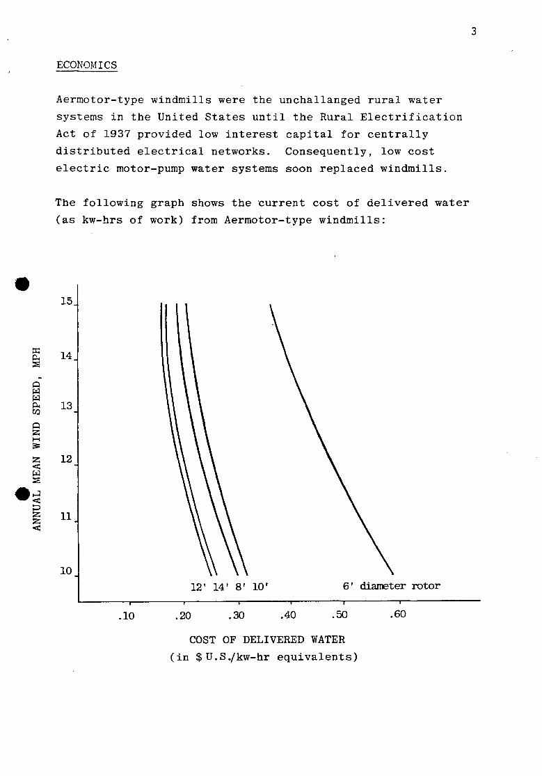
ECONOMICS
Aermotor-type windmills were the unchallanged rural water
systems in the United States until the Rural Electrification
Act of 1937 provided low interest capital for centrally
distributed electrical networks. Consequently, low cost
electric motor-pump water systems soon replaced windmills.
The following graph shows the current cost of delivered water
(as kw-hrs of work) from Aermotor-type windmills:
12' 14' 8' 10' 6' diameter rotor — i 1 1 1 1 1
.10 .20 .30 .40 .50 .60
COST OF DELIVERED WATER
(in $U.S./kw-hr equivalents)

4
The preceding graph was derived from the following data
and procedures:
SPECIFICATIONS
Rotor diameter Head Life Punp
6 ' 9 5 ' 30 y e a r s 2" d i a .
8* 1 3 5 ' 30 y e a r s 2 " d i a .
1 0 ' 2 1 0 ' 30 y e a r s 2 " d i a .
1 2 ' 304* 30 y e a r s 2 " d i a .
1 4 ' 455* 30 y e a r s 2" d i a .
COSTS, SUS 4
Equipment I n s t a l l a t i o n O&M @ 1%/year In te res t^
$ 1 , 6 3 0 600 669
1 ,698
1 ,855 600 736
1 ,869
2 , 5 8 0 700 984
2 , 4 9 8
3 , 9 5 0 800
1 ,425 3 , 6 1 7
5 , 5 7 0 900
1 ,941 4 , 9 2 7
PERFORMANCE
Output, usg/hr Cp6^ ? Energy g Energy cos t
Mean Annual Wind Speed
10 mph 12 mph 15 mph
.81 104 130 .08 . 0 6 . 0 5
6 , 3 0 0 8 ,100 1 0 , 2 0 0 58£ 46£ 36£
121 156 195 .10 . 08 .06
1 3 , 3 5 0 1 7 , 3 4 0 2 1 , 5 4 0 30£ 23£ 18<?
99 127 159 .08 .06 . 0 5
1 7 , 1 0 0 2 0 , 0 5 0 2 7 , 6 0 0 32£ 27£ 20<?
128 165 206 .10 . 0 8 .06
3 1 , 5 0 0 4 1 , 1 0 0 4 9 , 9 5 0 25£ 19£ 16£
109 141 176 .10 . 0 8 . 0 5
4 1 , 2 5 0 5 2 , 8 0 0 6 6 , 0 0 0 26£ 20£ 16£
3. Based on information provided by Aermotor-Braden Industries, Inc., Conway, Arkansas 72032 USA and Dempster Industries, P.O. Box 848, Beatrice, Nebraska 68310 USA.
4. Equipment includes windmill, 40' tower, sucker rod, and pump. Well
casing, storage tank, and freight not included.
5. Interest computed at 10% compounded monthly, amoratized over 10 years.
6. Cp, Co-efficient of performance = Windstream energy across rotor Delivered energv as pumped water

5
To analyse the cost/benefits of indigenous windmills, three
designs which have been introduced and manufactured in the
third world by foreign professional development workers will
be considered. They are all assumed to have 10 year lives,
while in fact their actual working life is unknown.
P.
p pa pa a*. w Q 55
55 < pa s • J
< 55 55 <
15.
14
13
12
11
10
Polomo Sail Windmill' 16' diameter
Arusha Windmill 16.5' diameter
Horizontal axis
IS" .20 .30 —r-.40 !50~ ^60 /70~
COST OF DELIVERED WATER
( i n $ U . S . / k w - h r e q u i v a l e n t s )
7. Energy del ivered, kw-hrs = water pumped(#) x head(ft) x ^ x 8 7 6 0 h r s x l i f e ( y r s < 60 x d3,0O0
8. Energy cost = (system cost / energy delivered) x electric motor efficiency of .8
9. Data from Food from Windmills by Peter Fraenkel, Intermediate Technology Publications, LTD.; 9 King Street; London"WC2E 8HN United Kingdom.
10. Data from How to Construct a Cheap Wind Machine for Pumping Water, Brace Research Institute, MacDonald College, Ste. Anne de Belevue 800, Quebec, Canada.

6
The preceeding graph was derived from the following data:'
SPECIFICATIONS
Name Rotor diameter Head Life Pump
Polomo SWM 16* 9' 10 years 2" dia. cyl.
Brace S-rotor 18ft.2 area 10' 10 years 7" diaphram
Arusha Mill 16.5' 180' 10 years 2 dia. cyl.
COSTS, $US
Equipment Installation O&M @ 2%/year Interest*
$350 50 70 328
140 50 28 134
2,120 900 424
2,102
PERFORMANCE
Output, usg/hr Cp6^ Energy7 g
Energy cost
Mean Annual Wind Speed
10 mph
450 .005
1,100 73£
330 .06 911 382
12 mph
600 .005
1,450 55£
450 .05
1,370 26£
600 .10
29,738 18<?
15 mph
1,440 .006
3,530 23£
600 .04
1,647 21£
11. Data obtained from "VITA News", August 1978, page 6; a lso from Ujuzi Leo Indus t r i e s , P.O. Box 764, Arusha, Tanzania.

7
Small gasoline or diesel engine driven pumps are considered
options to windmills in certain water supply applications.
They are also used sometimes to suppliment windmills during
periods of prolonged calm wind.
Compared with windmills, the primary advantage of these engine-
pumps is low capital cost while high energy and maintainance
costs and short life are distinct disadvantages..
Low head and high head applications require different engine-
pump configurations both of which are compared with windmills
in the following examples:
Low Head Application - Head: 90' (5' suction). Demand: 50,000 - 100,000 us gallons per month
Manufacturer, type
Pump
WINDMILL
Aermotor, 6' 40' tower
dia.,
Positive displacement, single action 2" diameter
GASOLINE ENGINE12
Briggs & Stratton, 4 hp, 3600 rpm, Model 80200, air-cooled
Centri fugal, suet ion
System life
Pumping capacity (at mean wind speeds)
Lifetime system cost
30 years
10 mph -(21xl06
12 mph -(26xl06
15 mph -(34xl06
80 g/hr g/30yrs) 104 g/hr g/30yrs) 130 g/hr g/30yrs)
Equipment $1,630 Install 600 O&M, 1%/yr 669 Interest5 1,698
Total 4,597
100 - 500 hours
1,200 g/hr 600,000 g/500 hrs
Engine 115 Pump 85 O&M 30 Interest5, lyr 20 Fuel, 0.25 g/hr @ .625 load; 500 hrs; $l/g 125
Total 375
Cost per 1,000 gallons of water delivered
$0.22 US (10 mph) 0.18 US (12 mph) 0.14 US (15 mph)
$0.63 US

8
High Head Application - Head: 300' Demand: 90,000 - 150,000 us gallons per month
Manufacturer, type
Pump
System life
Pumping capacity (at mean wind speeds)
Lifetime system cost
Cost per 1,000 gallons of water delivered
WINDMILL
Aermotor, 12' dia., 40' tower
Positive displacement, single action, 2" diameter
30 years
10 mph - 128 g/hr (34xl06 g/30yrs)
12 mph - 165 g/hr (43xl06 g/30yrs)
15 mph - 206 g/hr (54x10s g/30yrs)
Equipment $3,950 I n s t a l l 800 O&M, 1%/yr 1,425 I n t e r e s t 5
Total
3,617
9,892
$0.29 US (10 mph) 0.23 US (12 mph) 0.18 US (15 mph)
GASOLINE ENGINE
Briggs & S t ra t ton , 4 hp, 3600 rpm, Model 80200, a i r -cooled
Dempster Model 76 r e c i p rocat ing pump coupled to a pos i t ive displacement, s ingle ac t ion , 2" d ia . cyl inder
100 - 500 hours
220 g/hr 110,000 g/500 hrs
Engine 115 Pump 750 O&M 30 I n t e r e s t 5 , l y r 87 Fuel, 0.25 g/hr @ .625 load; 500 h r s : $ l / g 125
Total
$0.90 US
1,107
As t h e s i z e of g a s o l i n e o r d i e s e l e n g i n e - p u m p s i n c r e a s e s , t h e i r
c o s t / b e n e f i t s improved m a r k e d l y due l a r g e l y t o t h e i r l o n g e r
l i f e wh ich r e s u l t s from w a t e r c o o l i n g . Such l a r g e e n g i n e - p u m p s
a r e w i d e l y u s e d i n l a r g e w a t e r demand a p p l i c a t i o n s .
In low demand a p p l i c a t i o n s w h e r e i n t e r m i t t e n t s u p p l y i s t o l e r a b l e o r
smoothed o u t w i t h s t o r a g e a n d / o r a s m a l l e n g i n e - p u m p , and where
c a p i t a l i s a v a i l a b l e , t h e c o s t / b e n e f i t s of w i n d m i l l s a r e
more f a v o r a b l e t h a n s m a l l g a s o l i n e e n g i n e - p u m p s .
12. Information from Briggs &. S t r a t t on , Milwaukee, Wisconsin and from Mathews Hardware Store , Perry, Kansas USA, a Briggs se rv ice center .

CONCLUSIONS AND RECOMMENDATIONS
9
Aermotor-type Windmills
Aermotor-type windmills are today the most cost effective,
small demand water pumping systems where centrally distributed
electricity is unavailable and annual mean wind speeds exceed
8 mph. Where centrally distributed electricity is available
at an average projected cost over 30 years of $0.14 (US) (in
regions of 15 raph mean annual wind speeds) to $0.24 (10 mph
regions) per kilowatt-hour, Aermotor-type windmills are cost
competative.
Capital availability is the primary obstacle to using Aermotor-
type windmills. Finance strategies for rural development
should consider windmills where the economic posture of a region
justifies this level of investment and centrally distributed
electricity is not available or imminent.
Aermotor-type windmill designs may be copied for local fabrication
as patents on these have expired. The fabrication process
requires metal casting, turning, bearings, galvanizing, and
gear cutting. These designs have been successfully modified
to circumvent unavailable processes and/or materials. 3
Development organizations should be encouraged to sponsor
the development of "windmill production packages". These
packages would include drawings, material specifications and
options, detail of fabrication processes, and available on-site
technical assistance. These packages would then be made available
to potential fabricators-users world-wide (see Indigenous packages
Today, tens of thousands of good, used Aermotor-type windmills
stand idle in North America in the wake of the spread of centrally
distributed electrical networks. Complete systems can typically
be purchased for $100 - $400 (US). Consideration should be
given to recovering and using this equipment.

10
Indigenous Windmills
Today in numerous situations world-wide, low-cost indigenous
windmill designs fabricated with local skills and materials
are providing water which otherwise would be drawn either
by people or animals, or not at all. The situations are
characterized by a low level of economic development and a
lack of capital financing structures.
These indigenous windmill designs can have world-wide impact
on the development and upgrading of water supplies. However,
the transfer and use of this technology has not occurred
because potential fabricators-users are unaware of their
potential. Where "outside" development workers have introduced
indigenous windmills, they have often been adopted, and the
accompanying increase in water supplies have increased the 14 quality of life.
The availability of quality information will do the most to
further the use of this technology. First, information which
documents existing designs in terms of required materials,
fabrication processes, and the engineering parameters of the
systems, subsystems, and components needs to be assembled.
Then this information should be assessed and upgraded through 15 state-of-the-art wind systems engineering. Hybrid designs
should then be evolved which synthesize this knowledge in
terms of specifically available materials, skills, fabrication
processes, and other relevant parameters.
Then complete "windmill production packages" should be developed
which would include drawings, material specifications and options,
and on-site technical assistance. The availability of these
"packages" should then be made known to potential fabricators-
users through national and local government channels, the
international development community, and other information
dissemination channels, including "How-to-build" workshops for
international development workers.

11
At the point of del ivery to a f ab r i ca to r -u se r , the "package" must be sold to insure maximum committment and to maintain i n t e g r i t y .
Once sold and in production, the above processes should then become an i t e r a t i v e learn ing process . What works? What does not? Why?
The above processes are already underway today through the e f fo r t s of various development o rgan iza t ions . The work of several of these groups i s reviewed on the following pages:
13. Marcus Sherman (P.O. Box 458, Hyannis Po r t , MA 02647 USA) r epor t s of a manufacturer in Bangkok, Thailand who has modified an Aermotor-type design t o circumvent gears and an o i l ba th ; Ron Alward (NCAT, Box 3838, Butte, MT USA 59701) r epor t s of a group of Mennonites in Paraguay tha t i s manufacturing a modified Aermotor-type design l o c a l l y .
14. The experiences r e l a t e d by Pe te r Fraenkel (see footnote 9) and by James Spain in Columbia (see following pages) a re two examples of the successful in t roduct ion of t h i s equipment.
15. There has been a resurgance of a c t i v i t y in wind system design in the United S ta te s s ince 1973 which i s r e f l e c t e d in pa r t by t he U.S. Department of Energy's 1979 budget of $60mfor wind energy resource development. Much computer software pe r t a in ing to wind system ana lys i s , design, and engineering has been developed by var ious companies and can be d i r ec t l y applied t o indigenous windmill design and fabr ica t ion processes .

AERMOTOR-TYPE WINDMILLS 12
ALBERT MAHR FARM, 1978 Lorenzo, Nebraska USA
The tower, rather than the standard galvanized steel angle i ron , was bu i l t from 4"x4" wood by Albert 's father in 1911. Rainfal l : 17"/year. TYPICAL WINDMILL
INSTALLATION ON A DRILLED WELL
AVERAGE WATER NEEDS
Typ«
Milking cow. per day
Dry cow or steer, per day
Horse, per oay
Hog, per cay
Sheep, per day
Chickens, per 100. per day
Bath tub. each filling
Shower, each time useo
Lavatory, eacn time used Flusn toilet, eacn fjiiing
Kitchen sink, per aay
Automatic washer, each fill 0 is h washer
Water Softener
»4-mch hose, per nour
ng
Other uses, par Derson oer dav
Gxllons
35
15
12 4
2
6
35
25-60
1 - 2 2 - 7
20
30-50
10-20
up to 1 SO
300
25
This windmill with water storage integrated into the tower provides water on demand and under pressure to the adjacent building.
from Aermotor Co.

Aermotor Dempster 13
Aermotor has produced more windmills than any manufacturer in the U.S. First introduced in 1888, they are now manufactured in Argentina.
THE OILING SYSTEM
The gears and bearings of the Aermotor are constantly flooded with oil from the supply in the gear case. The large oil ring supported by the pump rod yoke picks up oil from one of the gears on the down stroke and carries it to the cross shaft, thus keeping all of the upper bearings automatically lubricated.
A E R M O T O R P U M P I N G C A P A C I T Y
Diamaiar Capacity par Total Eiavaoon in Faat
Cylindar (Incftn)
Hour, Gallons SIZE OF AERMOTOR
«FI | B-18FI | 6 R I t Ft l 10 Ft 112 Ft I 14 Ft I 1« Ft
1*.
2 2'A 2 V: 2V« 3 3'/. 3VS 3V« 4 *V. 4Vi 4*4 5 5*. S 7 8
105 123 130 180 225 265 320
i 440
570
725
900
ISO 180 190 280 325 385 470 550 640 730 830 940
1.050 1.170 1.300 1.700 1.875 2.550 3.300
130 120 95 77 65 56 47
35
27
.— 21
—• 17
.~»
185 175 U 0 112 94 80 68
50
39
— 30
— 25
— 17
—
280 I 260 . 215 j 170 140 I 120 I 100 I 88 76 65 58 51 46
37
25 19
600 560 460 360 300 260 220 185 160 143 125 110 98 98 SO SO 55
28 I 41 22 | 31
1.000 920 750 590 490 425 360 305 265 230 200 180 160 140 130 100 85 65 SO
Caeacitfu » « .n .> . i n n rao" »<• iOD-o..m.n 5 . „ a ,n ,„, „,,, , . , n mm .on, , i ra . . . o w n i n g ,„ , 1 5 to 20 miMiutour ..no. rnt won u . o . . icroaios Mtfvarion or ooo-m.ra mo rmaueat Dumping C4otci:y op»^ounn.
A E H M O T O R WINDMILL SPECIF ICATIONS
M O O E L 7 0 S '
M ILL S IZE ( W H E E L OIA.)
(F««1)
STROKE (Inches)
I NO. OF ! SAILS
SHIPPING WEJGHT (Pounds)
10
16
iVz 4 3 I 8 4 6 |
210 355
10 & 7 '^ _!» I 12 4 9
16 4 12
18
18 24S0 'Mode* 7P2 windmills wera introduced in 1S33.
AERMOTOR WATER SYSTEMS BRADEN INDUSTRIES, INC. CONWAY,. ARKANSAS 72032 USA 1-501-329-2969
4 B I J U K I
1 B I
3ro t *i°.*"°i2
261
373
510
1178
'.460
BACK GEARED WINDMILLS
PUMPING CAPACITY
Tnew CJO*cit»»» are U M O on • li^rtmmtom tVmtf mnc tot ttrm\ rry>»t af< l& hi 20 mil o* tour «">a '» n'tm mur* C^oKJtwf «r* onea on W|«i t ATOM of Ovmestw rmiii. if vwn itrojut liCC CJ34K
la i
1T4
2
2 * 2V,
2 *
3
3tt
314
3 * 4
r M M Om- i m .
120
95
75
62
54
45
» 34
29
:s
115
130
165
206 241
294
346
400
457
522
172
135 107
89
77
65
55
41
42
37
•>* 173
195
241
304
370
440
563
600
681
?so
1*-Omt.
256
210
165
137
119
102
66
75
65
57
a w t-r-M.
140
159
202 241
100
357
416 417
556
535
i r t n u On a m
388
304
240
200
173
147
125
ioa 94
S3
180
206
260
322
390
463
544
630
724
_S2_
i r S M M
530
455
360
300
260
220
187
162 142
!24
159
176
222
276
334
396
465
540
620
706
i! tt»f wind vwocitv ba inensasaa or oaenmad. mm Omr*o*n% CJsOtcity o* the mmnami* w>ri a>u o« incfUMa or u K r u u a Caoacitit w«i ca ftoucto Motu>m«a*v n rano***. if <*wxi wetoctv >• hns than IS Ttii«t WK nowr: 12 m«ie per neur •nia cioKity reoucafl totxaumM*** 20V 10 mm p*y now « M 4 cafitfory raaucad aocroitfrnafaty 36%
WHEEL CAN'T COME LOOSE Wrtael apider * manV with a aplit huh whtrhclampa amend the wheel ahaft A heavy steel heat-bvaU'd bnlt elampa the aptder aecurely to th*> ahaR - making it impoaaible fur the wheel to come lonae
sctnmriCAUY OKICNCD FAWS utilize the full powff o* the wind Farw are made from heavy gauge steel and securely fastened to circles to keep proper curvature and position. They cannot spring out of shape Thoroughly galvanised wheel is not affected by atmospheric conditions
I A U MAfMHC TURNTABLE allows qu<k response BaH races vt semi-steel, speciairy hardened and finished smooth to permit balls to rotl (reefy Enough balls an used to withstand five times the toad they carry
VANE WON'T SAG OR BUCKLE Made of ana,IF tteel. cnmptetely galvanised and sturdily braced, the van* atetw i* built tn Urt for yeara
WACIflNf^UT COUAllZtftC C U M work inde pendentty of each mhe» on a steel heanrtg Gears run -n an oil bath Machine cut gears and piniorn give Derfect bearing surface over full wKfth ot Ihe cog-each gear ca'nes >ts full curt of the KWK)
INTfftHAL [XPANOINC BRAKC com bines best features ol both the steel band brake and cast snoe brake Has heavy casi shoe and special steel brake lining,
MAtn SHAFT ASSEMILY should never wear out. Tapered roller bearings absorb the thrust and wear of the shall Provide? quicker, smoother pumping starts.
Dempster has manufactured windmills for over 40 years and is the 'other' windmill company in the U.S.
DEMPSTER INDUSTRIES P.O. BOX 848 BEATRICE, NEBRASKA 68310 USA 1-402-223-4026

Sparco 14
The Sparco is a new arrival on the windmill scene. Its low cost is quite welcomed and it is capable of handling low head water supply problems. The manufacturer says there are over 30,000 installations to date, its life span is unknown. The following information is provided by the manufacturer:
- Ball bearings on crankshaft - 50" rotor with self-feathering
blades
- Will pump 30 gallons per hour in 7 mph wind speeds or greater (The head is not specified.)
- Semi-annual greasing
•- Installation by one person in 30 , minutes
- $345 (US) with diaphragm pump
- $395 (US) with piston pump capable of 33' lift (46' to discharge point)
For additional information, contact the exclusive North American distributor:
Enertech Corporation P.O. Box 420 Norwich, VT 05055 USA 1-802-649-1145

INDIGENOUS WINDMILLS 15
Of the indigenous windmills, the sail windmill design is the most widely used today and is integral to agriculture throughout the Mediterranean and southeast Asia.
Hundreds of sail windmills on the Island of Crete
SAIL WINDMILL
Fig. J. Cross Section through Typical Cretan Wind Pump
Appropriate Technology Vol 2 No J
No. I. Daby Jumbo Windmill. Mo. t, Ordinary J am bo. No. 1. Hci*w Jumbo, No. 4. Mcrry-fo-nmnd, mettnMd. Ko.&. Giant U«rrr-c»>rau&d. Mo. a, UtttUO'fvx WindtnUL
No. T. CUnc flattle-ax. Na a. llollurul M(1L No. v. QU&tTurolna Wltyjail'l No. 10. ifocli TurtJtne (roildcrleMl. No. IL Mock Turbine (witti ruddtT).
Many U.S. farmers and ranchers built their windmills in the early 1900's.
FROM: HOMEMADE WINDMILLS OF NEBRASKA by Erwin Hinckley Barbour^ University of Nebraska Ag. Bull. 59, 1899.

POLOMO 16
The Polomo sail windmill was copied from traditional Mediterranean designs and adapted to pumping water for irrigation from the Omo River in Ethiopia by Mr. E.O. Pollock and the Rev. J.R. Swart of the Omo American Mission. The design is built entirely in Ethiopia and is used by native Geleb farmers who purchase the windmills for $5.00(Eth.) per year from the Mission. As of 1975 there were 19 of these windmills in use over a 10 km stretch of the Omo. These windmills enabled the Geleb to obtain three crops per year from their land as opposed to the traditional single harvest per year and the accompanying prosperity has made the windmills much sought after.
~1 «-bn
POLOMO SAIL WINDMILL, 16' ROTOR
o c O « • -S-
a.
c • r —
o
CD O
o
10.
05.
0
* *
*
*x X
* -
A ....... .. ,
X X
Number of lines = number of sails open to the wind
* *
i i
10 15 Mean Wind Speed
20
Protecting windmills against high winds is an important design consideration. The Polomo design takes advantage of the farmer's presence to manually control i t , and neighborhood habits when he is absent:
"Sails on the traditional Cretan wind sails are generally reefed by rolling them around the arms of the wheel, but this is not a practical means in southern Ethiopia as cloth, being a rare and valuable conraodity, is likely to be taken during the night (and sails are taken home at night)."
FROM: FOOD FROM WINDMILLS by Peter Fraenkel, 1975; Intermediate Technology Publications, LTD.; 9 King Street; London WC2E 8HN United Kingdom.
PERFORMANCE OF 14' WINDMILL

SWD Slffl, the Steering Committee for Wind Energy in Developing Countries (P.O. Box 85, Amersfoort, The Netherlands) is leading the way in the development of wind energy resources in developing countries. Comprised of three Universities, a group of research scientists, and a group of private engineers, SWD is asking the right questions and is answering them with excellent publications, designs, and hardware.
SWD
"Wind energy utilization in Sri Lanka; potentialities and constraints."
"Literature survey; horizontal axis fast running wind turbines for developing countries."
"Model for cost comparison of windmills with engine pumps."
"Performance characteristics of some sail and steel bladed windrotors."
CONSTRUCTION MANUAL FOR A CRETAN WINDMILL
The manual details a design using mostly wood components. Details for constructing a wood lathe with which to build the windmill are included as well as instructions for drilling and casing a well.
PUBLICATIONS
"Feasibility study of windmills for Water Supply in Mara Region, Tanzania."
"Rotor design for Horizontal Axis Windmills."
"WIND AND SUN COMPENDIUM" is a newsletter for the development of wind and solar energy for water pumping available only to contributors. Write: Compendium, TOOL Foundation, Mauritskade 61 a, Amsterdam.
for Community vi/atsr Sep?"'

Windworks 18
' In 1974, Windworks (Route 3, Box 44-A; Mukwonago, WI 53149 USA) designed a sail windmill which in terms of materials and fabrication processes stands somewhere between a Cretan design and an Aermotor. It uses a (salvage) automobile differential as its backbone, and the 'driveshaft' extends to the ground to provide rotary power.
While requiring welding, cutting, and drilling of metal, fabrication does not require forging, lathe work, or galvanizing. The octahedron module tower uses 40% less steel than traditional angle iron designs while providing the same strength, and a wood tower can be substituted. With its 25' diameter rotor, oil bath gears, oversized ball bearings, and primarily steel construction, this design is capable of 4-6 hp of work for many years.
Brace Research Institute (Ste. Anne-de-Bellevue 800; ^kiebec, Canada) built a second generation of this
design to gain experience with it and review the 15 page set of detailed blueprints and the 22 page construction manual which are now available through Brace.
Arusha In 1974, Dick Stanley, a foreign development worker, undertook to design a windmill which could be built with local skills and materials in Arusha, Tanzania. The result is the Arusha design which is now manufactured and sold by a local co-operative, UJUZI LEO INDUSTRIES:
mbo. box 764, Arusha, Tanzania.
New Scientist, 14 September 1978: TTFe windmill) ...is so simple that anyone can make it, and if someone with more skill and experience opened up in competition, 'they could overrun the co-op tomorrow. I've lost alot of sleep over this,' Stanley admits.
In 1975, Rockwell International was mandated by the U.S. Dept. of Energy to build a small wind electric industry. Several small wind businesses were funded in hopes they could survive with the major corporations in the field. Same goal as Stanley, different motivation, should be an interesting set of experiments.
THE ARUSHA WINDMILL: A CONSTRUCTION MANUAL is a v a i l a b l e from VITA, 3706 Rhode I s l and Ave. ; Mt. R a i n i e r , MY 20800 USA f o r $3.75 p o s t p a i d .
OCaCflTFTXW ANO SPCOnCATIONS
A#t«rtt«»y loot*? moo* waav oumpng
U M I an •ooaranfc V M * tortar arm at a
mat w a r n <* tan and tat 270 Hx. wot) apprevnataowjrai w a V * 800 fca. can da%«iap 3 tfiaft no n • 1S men mnd has a ounong rata c< 600 att/hr m a 12 mon w m wan a i W haad and a 2"
i as taw as 6 can pump a t i
cut-out spaad of 20 rnpn can pump flront dapsat as ̂ raal at 250'
linatwodaypanod aBfnowxfparaarawPwi—andbaar' inga or aajjctwd win rnaennad. aaatfy
«a*ry tranaooflM to mtm on a long onaa-sa Lanofuvar aquBpart wOi a.amp* root rack cofflMraDfti to hand pump o panooi of no «md
C09TAMOSUPFLT
Shi tS000(orUSSlS2S)
1500 (or US* 193) dby:
> ur* axanatfi at 3 *

New Alchemy Institute 19
The New Alchemy Institute (P.O. Box 432, Woods Hole, MA 02543 USA) sail-wing windmill is a downwind design. High speed governing is provided automatically with a spring-cable mechanism in the sails' trailing edges which allows unattended pumping. The backbone of the design is a salvage crankshaft from an automobile engine.
X mmWfweCt* -****•
« * * t»iua * i ' | x" •**** ******
— ' x-' -t—• srvv—.->—i L n ~ ! II -t
€
te «~as UL
|, * UDFaoCATUe*
N
«ui
I I
u
^ N
Fipnw I
DIAPHRAGM PUMP
Build around a tire
WOODEN TOWER
ITDG
Oil l e v e l
SffiS
INITIAL PSEPJUUTIOM.
Six tlaber into shape of as oblong block eonewhat larger than the O.D of the f inished bearing to allow for ahnnkags and bore being off centra. Bore hole through centre of block the s i z e of the journal.
DiXTOHATION
Soon after submerging the bearing blocks in hot groundnut o i l , many surface bubbles 1H i n diameter, oade from a multitude of smaller bubbles, w i l l appear on the surface.
\s<<\\ n u n u l l Heater
la the moisture contest of blocks i s reduced, the surface bubbles w i l l become s a a l l e r i n s i z e .
— When the surface bubbles are formed from s ingle streams of p in-s ize bubbles, the dehydrat ion process has gone far enough. Stop heating, and l e t blocks cool in the o i l overnight.
Intermediate Technology Development Group, founded by E.F. Schumacher in 1965, has since led the way in introducing a broad range of technologies which can be built with local materials and skills to the Third World. They offer a wide range of publications and a quarterly journal, Appropriate Technology ($10 US, h4). North Americans write international Scholarly Book Service, Inc.; P.O. Box 555, Forest Grove, OR 97116 USA; everyone else write: Intermediate Technology Publications LTD., 9 King Street; London WC2E 8HN United Kingdom.
From: "Oil Soaked Wood Bearings", Appropriate Technology, Vol. 2:4.

SAVONIUS ROTORS 20
The Savonius rotor was invented by Captain Sigurd Savonius, a Finn, in 1924. He developed and marketed the rotor primarily as a water pumping windmill.
Savonius rotors never seriously challanged Aermotor-type windmills due to their higher cost. However, their vertical axis design and the fact they can be easily fabricated from oil drums which are widely available at reasonable cost in developing areas makes the rotor a possible option when undertaking the local fabrication of water pumping windmills.
Typically, the rotor would be compared with a horizontal axis windmill such as a Cretan sail windmill. Two design parameters help
^jstinguish which windmill is best suited to an application. First, and most important, is the amount of water required. The Savonius is a low yeild machine due to its small swept area and is capable of pumping 100-200 gallons (US) per hour against a 10' head in an 8-12 mph mean wind. This amount of water is quite sufficient for domestic supplies for several families but is not enough for irrigation in most cases. Second, where oil drums are available and inexpensive, the Savonius can be easily fabricated at a low cost. Wood bearings may be used, and assembly requires cutting, fasteners, and plumbing pipe.
Savonius' have been criticized for not pumping as much water as sail windmills,
«r example in Food from Windmills. Again, ey have a much smaller area exposed to
the wind than a sail windmill and their application is limited to low demand situations.
;~x
SAVONIUS ROTOR IN OCTAHEDRON MODULE TOWER
55 GALLON OIL DRUM
SPEED LIMITATION DEVICE
Eric Brunet, 1975

CI AT
META REGION, COLOMBIA
This Savonius rotor provides water for approximately 100 beef cattle, and domestic water for a family of five.
W i i s is one on several rotors built in this region of Colombia since 1971 under the direction of Dr. James Spain (Rockefeller Foundation, 1133 Avenue of the Americas, NY, NY 10036 USA) working with the Beef Production Team of Centro Internacional de Agricultura Tropical of Cali, Colombia.
Traditionally, water for cattle in this region has been provided by numerous streams. However, Dr. Spain writes, "The cattle get mired down in mud holes attempting to get to water in streams and the older, lactating cows are rarely able to recover from spending more than just a few hours in a mud hole. Therefore, losses are very high, and a windmill
21
could easily be paid for in a single season. Conventional windmills were manufactured in Colombia...but quality control was poor and people have very little confidence in this type of solution to the water problem."
This design uses a V-belt drive to step rotor speed down 1/3 and drive a positive displacement pump (2" piston). The pulley to the left of the rotor and above provides eccentricity for the pump. This pulley is drilled so that the pump stroke can be varied from 5-20 cm to adjust for a seasonal variation in water depth of 2-13 meters.
Dr. Spain estimates the machine pumps 1 liter per second from 6 meters and 1/2 to 2/3 liters per second (475-625 gallons us per hour) from 8 meters, both in an estimated 12 mph wind.

Brace Research Institute 22
The Brace Research Institute (Ste.-Anne-de-Bellevue 800; Quebec, Canada) was founded in 1961 with the mandate to develop water resources in developing countries. Since then, they have provided numerous publications concerning wind energy, solar distillation and crop drying, and other technologies related to developing water resources.
They built a 33' diameter windmill water pump for irrigation in Barbadoes in the late 1960's. This machine used a truck differential as its backbone and the fiberglass blades used were the result of one of the most thorough aeroelastic analyses performed at that time.
Their booklet, "How to Construct a Cheap Water Pumping Windmill" (1964) provides a detailed set of instructions for fabricating a Savonius rotor. However, this design requires unnecessary welding and machine work which could be unavailable in developing areas. Also, the Fafnir bearings specified are not designed for the axial loading of the rotor and will fail in less than two years.
PERFORMANCE OF SAVONIUS ROTOR
40Qi
300
O.
£20C
3 O
3 O- 10c
Head - 9.8' Two drum rotor
Area - 18'2
Diaphragm pump
8 10 12 -T" 14
Wind Speed (mph)
POWER CHARACTERISTICS FOR RANGE OF WINDMILLS
33' WINDMILL-ON BARBADOES
O
U c <v o
0)
o o en
A B c D
Savonius rotor Aermotor-type Fourbladed Sail Windmill,
2 3 4
Tip Speed Ratio

IRRI 23
In 1975, the International Rice Research Institute (P.O. Box 933, Manila, Philippines) under the direction of Bart Duff, Agricultural Economist, began investigating Savonius rotors for rice irrigation.
Perhaps the most unique aspect of the work which has followed is the adaptation of a 'tubular' pump to the rotor. A suction pump, it is capable of lifting water 20'f and with heads less than the length of a horizontal arm of the pump the pump does not need a foot valve and is self-priming. This pump allows the rotary motion of the Savonius' center shaft to be used directly, rather than changing this rotary motion to reciprocating motion for driving piston or
fteaphragm pumps. It also allows the use ^Wf standard plumbing pipe and couplings
throughout the fabrication process, both for the central shaft of the Savonius and for the pump. This greatly simplifies the fabrication process and the locating of materials. IRRI SAVONIUS ROTOR AND TUBULAR PUMP
30-<
20.
ro
CO
*> 10. Q. +J 3
O
0-
I V x I V pump
T
1" x 1" pump
Pump: L i f t - 4' Arm - 4' rad.
Windmil l : Diameter - 4 ' Height - 8 . 5 '
T -12
—r-15
—r~ 18
Wind Speed (mph)
H.t.r —I u
U-J, S"3 £» —-£<7?^- T - ' wnTW-
/ » M , "3 < >i U WeH
f-r'^t^-^
/ / /
j ESTIMATED PUMPING PERFORMANCE
SAVONIUS ROTOR AND TUBULAR PUMP
from IRRI
SCHEMATIC OF TUBULAR PUMP
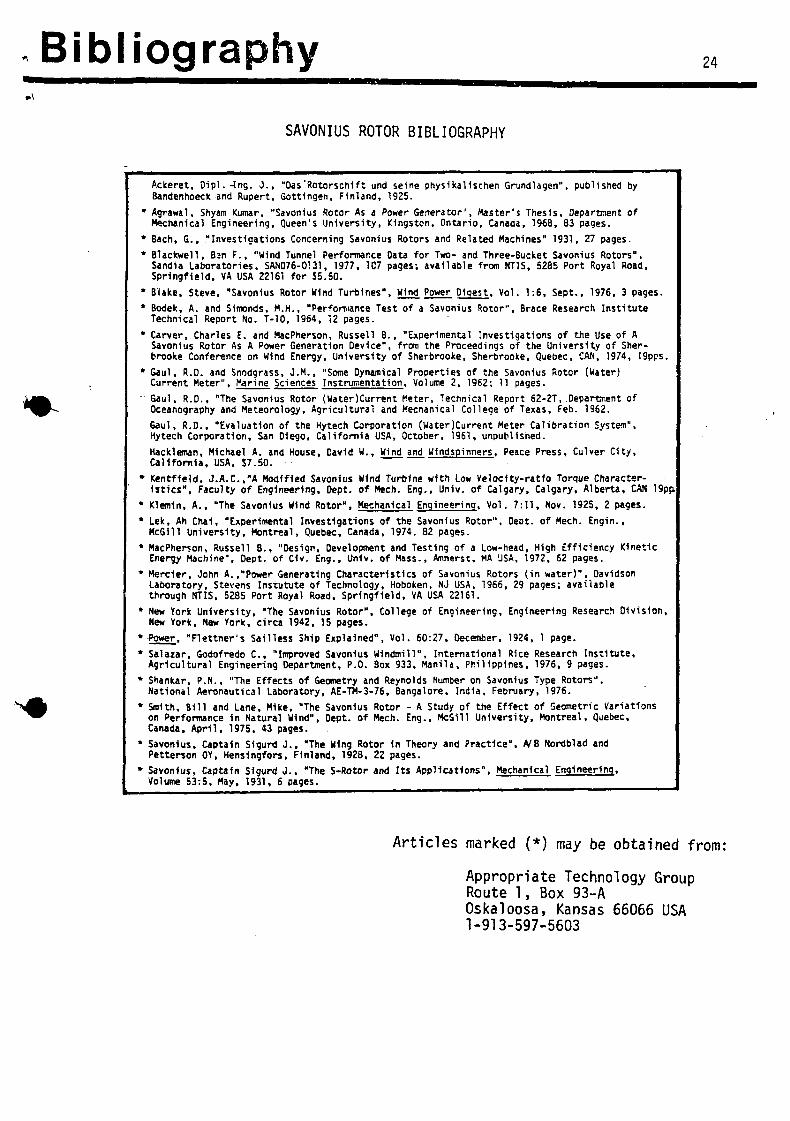
Bibliography 24
SAVONIUS ROTOR BIBLIOGRAPHY
Ackeret, Oipl. -Ing. J., "Das'Rotorschlft und seine physlkalischen Grtindlagen", published by Bandenhoeck and Rupert, Gottingen, Finland, 1925.
* Agrawal, Shyam Kumar, "Savonius Rotor As a Power Generator", Master's Thesis, Department of Mechanical Engineering, Queen's University, Kingston, Ontario, Canada, 1968, 83 pages.
* Bach, G., "Investigations Concerning Savonius Rotors and Related Machines" 1931, 27 pages.
* Blackwell, Ban F., "Wind Tunnel Performance Data for Two- and Three-Bucket Savonius Rotors", Sandia Laboratories, SAND76-0131, 1977, 1C7 pages; available from NTIS, 5285 Port Royal Road, Springfield, VA USA 22161 for $5.50.
* Blake, Steve, "Savonius Rotor Wind Turbines", Wind Power Digest. Vol. 1:6, Sept., 1976, 3 pages.
* Bodek, A. and Simonds, M.H., "Performance Test of a Savonius Rotor", Brace Research Institute Technical Report No. T-10, 1964, 12 pages.
* Carver, Charles E. and MacPherson, Russell 8., "Experimental Investigations of the Use of A Savonius Rotor As A Power Generation Device", from the Proceedings of the University of Sher-brooke Conference on Wind Energy, University of Sherbrooke, Sherbrooke, Quebec, CAN, 1974, 19pps
* Gaul, R.D. and Snodgrass, J.M., "Some Dynamical Properties of the Savonius Rotor (Water) Current Meter", Marine Sciences Instrumentation, Volume 2, 1962; 11 pages.
' Gaul, R.D., "The Savonius Rotor (Water)Current Meter, Technical Report 62-2T, Department of Oceanography and Meteorology, Agricultural and Mecnanical College of Texas, Feb. 1962.
6aul, R.D., "Evaluation of the Hytech Corporation (WaterjCurrent Meter Calibration System", Hytech Corporation, San Diego, California USA, October, 1961, unpublished.
Hackleman, Michael A. and House, Cavld W., Wind and Wlndspinners, Peace Press, Culver City, California, USA. $7.50.
* Kentfleld. J.A.C.'A Modified Savonius Wind Turbine with Low Velocity-ratio Torque Characteristics", Faculty of Engineering, Dept. of Mech. Eng., Univ. of Calgary, Calgary, Alberta, CAN 19pp.
* Klemln, A., "The Savonius Wind Rotor", Mechanical Engineering. Vol. 7:11, Nov. 1925, 2 pages.
* Lek, Ah Cha1, "Experimental Investigations of the Savonius Rotor", Deot. of Mech. Engin., McGill University, Montreal, Quebec, Canada, 1974. 82 pages.
* MacPherson, Russell 8., "Design, Development and Testing of a Low-head, High Efficiency Kinetic Energy Machine", Oept. of C1v. Eng., Univ. of Mass., Amherst, MA USA, 1972, 62 pages.
* Merder, John A.,"Power Generating Characteristics of Savonius Rotors (in water)", Davidson Laboratory, Stevens Instutute of Technology, Hoboken, NJ USA, 1966, 29 pages; available through NTIS, 5285 Port Royal Road, Springfield, VA USA 22161.
* New York University, "The Savonius Rotor", College of Engineering, Engineering Research Division, New York, New York, circa 1942, 15 pages.
» -Power. "Flettner's Sailless Ship Explained", Vol. 60:27, December, 1924, 1 page.
* Salazar, Godofredo C , "Improved Savonius Windmill", International Rice Research Institute, Agricultural Engineering Department, P.O. Box 933, Manila, Philippines, 1976, 9 pages.
* Shankar, P.N., "The Effects of Geometry and Reynolds Number on Savonius Type Rotors", National Aeronautical Laboratory, AE-TM-3-76, Bangalore, India, February, 1976.
* Smith, Bill and Lane, M1ke, "The Savonius Rotor - A Study of the Effect of Geometric Variations on Performance 1n Natural Wind", Dept. of Mech. Eng., McGUl University, Montreal, Quebec, Canada, April, 1975, 43 pages.
* Savonius, Captain Sigurd J., "The Wing Rotor 1n Theory and Practice". A/B Nordblad and Petterson 0Y, Hensingfors, Finland, 1928, 22 pages.
* Savonius, Captain Sigurd J., "The S-Rotor and Its Applications", Mechanical Engineering, Volume 53:5, May, 1931, 6 pages.
Articles marked (*) may be obtained from:
Appropriate Technology Group Route 1, Box 93-A Oskaloosa, Kansas 66066 USA 1-913-597-5603