
wimax_module1
29
National Institute of Standards and Technology – Draft 1.2.1 - 1 - The Network Simulator NS-2 NIST add-on IEEE 802.16 model (MAC+PHY) January 2009
Transcript of wimax_module1

National Institute of Standards and Technology – Draft 1.2.1 - 1 -
The Network Simulator NS-2
NIST add-on IEEE 802.16 model (MAC+PHY)
January 2009

National Institute of Standards and Technology – Draft 1.2.1 - 2 -
Table of Content
1 Overview................................................................................................................................. 4 2 Glossary .................................................................................................................................. 4 3 Packet CS ................................................................................................................................ 4
3.1 Classifier class structure ................................................................................................. 5 3.2 DestClassifier example .................................................................................................. 5 3.3 TCL commands .............................................................................................................. 6
4 MAC sublayer ......................................................................................................................... 6 4.1 MAC module structure ................................................................................................... 7 4.2 Addressing and connection ............................................................................................ 8 4.3 MAC PDU format .......................................................................................................... 9
4.3.1 Packet header structure .............................................................................................. 9 4.3.2 Defined Management messages .............................................................................. 10
4.4 Construction and transmission of MAC PDUs ............................................................ 10 4.4.1 Fragmentation .......................................................................................................... 10 4.4.2 Packing .................................................................................................................... 10
4.5 ARQ ............................................................................................................................. 11 4.6 Scheduling services ...................................................................................................... 11
4.6.1 Schedulers ................................................................................................................ 11 4.6.2 TCL commands ....................................................................................................... 12
4.7 Bandwidth allocation and request mechanisms ........................................................... 12 4.7.1 Contention resolution............................................................................................... 12 4.7.2 TCL commands ....................................................................................................... 13
4.8 MAC support of PHY .................................................................................................. 14 4.9 Network entry and initialization................................................................................... 14 4.10 Ranging ........................................................................................................................ 15 4.11 QoS .............................................................................................................................. 16
4.11.1 TCL commands ................................................................................................... 17 4.12 MAC layer handover procedures ................................................................................. 17
4.12.1 Scanning .............................................................................................................. 17 4.12.2 TCL commands ................................................................................................... 18
4.13 Frame structure ............................................................................................................ 19 4.14 Packet processing ......................................................................................................... 20
5 PHY ...................................................................................................................................... 23 5.1 OFDM PHY ................................................................................................................. 23
5.1.1 OFDM physical layer class diagram ........................................................................ 23 5.1.2 OFDM Packet schedulers ........................................................................................ 24 5.1.3 TCL Configuration .................................................................................................. 24
5.2 OFDMA PHY .............................................................................................................. 25 6 Configuration ........................................................................................................................ 25
6.1 Setup ............................................................................................................................ 25 6.1.1 Configure the node .................................................................................................. 25 6.1.2 Configure a packet classifier ................................................................................... 25 6.1.3 Configure a scheduler .............................................................................................. 26 6.1.4 Configure the channel .............................................................................................. 26
6.2 Statistics ....................................................................................................................... 26 6.3 Tracing ......................................................................................................................... 27

National Institute of Standards and Technology – Draft 1.2.1 - 3 -
7 Parameters and Constants ..................................................................................................... 27 7.1 Parameters .................................................................................................................... 27
8 Annexes ................................................................................................................................ 28 8.1 Current known issues ................................................................................................... 28 8.2 FAQ .............................................................................................................................. 29
9 References............................................................................................................................. 29

National Institute of Standards and Technology – Draft 1.2.1 - 4 -
1 Overview The model currently implemented is based on the IEEE 802.16 standard (802.16-2004) and the
mobility extension 80216e-2005. A snapshot of available and missing features is listed below:
Available features Summary of features NOT implemented
- WirelessMAN-OFDM physical layer
with configurable modulation
- Time Division duplexing (TDD)
- Management messages to execute
network entry (without authentication)
- Default scheduler providing round
robin uplink allocation to registered
Mobile Stations (MSs) according to
bandwidth requested
- IEEE 802.16e extensions to support
scanning and handovers
- Fragmentation and reassembly of
frames
- WirelessMAN-OFDMA
- Frequency Division duplexing (FDD)
- ARQ (Automatic Repeat Request)
- Service Flow and QoS scheduling
- Periodic ranging and power
adjustments
- Packing
- Error Correction
It is important to note that many components are not defined in the standard. Therefore the model
implements one solution, which may or may not fit the user’s need. This is the case for the
bandwidth scheduler, and flow handler, or scanning scheduler. The model was designed to be
relatively extensible.
2 Glossary BS: Base Station
CID: Connection Identifier
CS: Convergence Sublayer
MAC: Media Access Control
MIB: Management Information Base
MS: Mobile Station
OFDM: Orthogonal Frequency Division Multiplexing
OFDMA: Orthogonal Frequency Division Multiple Access
PDU: Protocol Data Unit
PMP: Point to MultiPoint
PS: Physical Slot
RTG: Receive/transmit Transition Gap
SAP: Service Access Point
TTG: Transmit/Receive Transition Gap
3 Packet CS The CS layer resides on top of the MAC layer and performs the following functions:
- Receives higher-layer PDUs
- Perform classification

National Institute of Standards and Technology – Draft 1.2.1 - 5 -
- Deliver the CS PDUs to the MAC SAP
- Receives CS PDUs from the peer entity
In the current implementation, the Packet CS only performs classification. The method used to
classify packets is implementation dependent. It may also be useful to implement multiple
solutions in order to find the appropriate connection. The model supports user-defined classifiers.
3.1 Classifier class structure
Figure 1: Packet classifier class diagram
To implement a new classifier, subclass the SDUClassifier class and implement the classify
(Packet *) method. The SDUClassifier supports priority, which can be used to specify the order
in which the classifiers are called. The smaller the priority value, the sooner it will be called
(default value=0).
Note: The priority must be set prior to adding the classifier into the MAC since it is used to order
the list of classifiers.
3.2 DestClassifier example
The DestClassifier class can be used as a reference to implements more complex packet
classifiers. It uses the destination IP address to classify the packets.

National Institute of Standards and Technology – Draft 1.2.1 - 6 -
Figure 2: Flow diagram for DestClassifier
As show in Figure 2, the DestClassifier uses the destination MAC address located in the packet
(and computed at the routing level) and the packet type to determine the proper CID. If there is no
match, it will return -1.
3.3 TCL commands $classifier set-priority $prio
Change the classifier’s priority. Default value is 0.
$mac reset-classifiers
Clear the list of classifier in the MAC. This must be called before adding custom packet classifier.
$mac add-classifier $classifier
Add classifier to the list of packet classifiers to use.
4 MAC sublayer This section presents the MAC sublayer that currently supports PMP.

National Institute of Standards and Technology – Draft 1.2.1 - 7 -
4.1 MAC module structure
Figure 3: MAC 802.16 class diagram
The Mac802_16 is a subclass of the Mac class. It is an abstract class that contains the common
elements of the BS and MS. For example it stores the MAC MIB and PHY MIB. It is the
interface with other layers for sending and receiving packets. Figure 3 shows the class and the
relations with other modules.
A MAC has a list of packet classifiers (SDUClassifier) that maps each outgoing packet with the
proper connection identifier (CID). Using TCL, the user configures the list of classifiers to be
used (see section 3). The current implementation uses the destination IP address as the classifying
element.
The ServiceFlowHandler is responsible for handling flow requests/responses. It also stores the
list of flows for the node.
A SS is registered to a BS, and a BS can be connected to multiple SSs. The class PeerNode
contains information about the peer, such as its connections and status. The Connections are also
accessed via the ConnectionManager, which contains the list of incoming and outgoing
connections.
The WimaxScheduler abstract class is used to create an interface with the MAC. There are mainly
two types of schedulers: one for the BS, and one for the SS. Since the scheduler is specified in
TCL, it is easy to implement the abstract class and change it.
Finally, the MAC computes statistics via StatWatch and ThroughputWatch objects for packet and
traffic information. The values are used to trigger events, but can also be printed during the
simulation for post processing.
Since a BS and an SS have different state machines we defined 2 subclasses, namely
Mac802_16BS and Mac802_16SS, as shown below.

National Institute of Standards and Technology – Draft 1.2.1 - 8 -
Figure 4: classes Mac802_16, Mac802_16BS and Mac802_16SS
4.2 Addressing and connection Each MAC has a unique address coded as an int that is defined in the MAC class of NS-2.
The model also defines connection identifiers as int but they are carried as 16-bit in the messages.
The CIDs are assigned according to section 10.4 of [1] during initialization and dynamic setup of
connections.
The following connections are created during initialization at the BS:
- Initial Ranging (incoming and outgoing)
- Padding (incoming and outgoing)
- Broadcast (outgoing)
- Adaptive Antenna System (AAS) (outgoing, not used)
The following connections are created during initialization at the SS:
- Initial Ranging (incoming and outgoing)
- Padding (incoming and outgoing)
National Institute of Standards and Technology – Draft 1.2.1 - 9 -
- Broadcast (incoming)
Additionally, during network entry the following connections are setup and CIDs assigned:
- Basic CID (incoming and outgoing)
- Primary CID (incoming and outgoing)
- Secondary CID (incoming and outgoing)
- Data CIDs. Currently the model only supports one data connection.
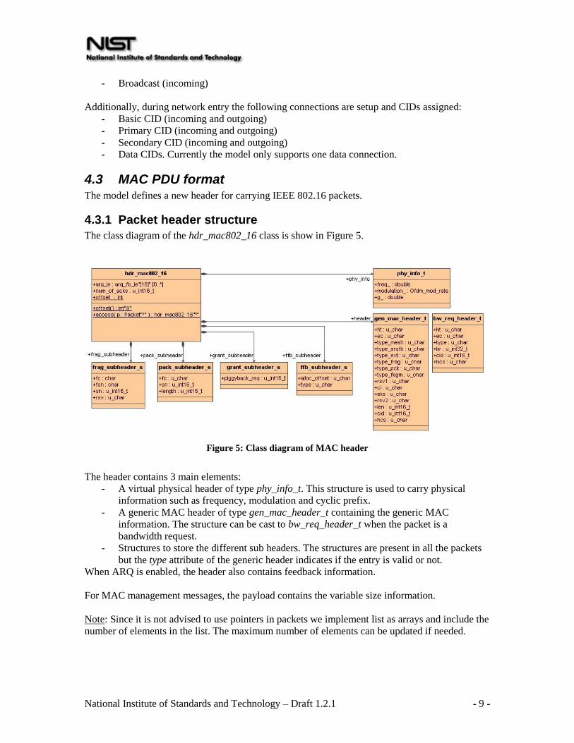
4.3 MAC PDU format The model defines a new header for carrying IEEE 802.16 packets.
4.3.1 Packet header structure
The class diagram of the hdr_mac802_16 class is show in Figure 5.
Figure 5: Class diagram of MAC header
The header contains 3 main elements:
- A virtual physical header of type phy_info_t. This structure is used to carry physical
information such as frequency, modulation and cyclic prefix.
- A generic MAC header of type gen_mac_header_t containing the generic MAC
information. The structure can be cast to bw_req_header_t when the packet is a
bandwidth request.
- Structures to store the different sub headers. The structures are present in all the packets
but the type attribute of the generic header indicates if the entry is valid or not.
When ARQ is enabled, the header also contains feedback information.
For MAC management messages, the payload contains the variable size information.
Note: Since it is not advised to use pointers in packets we implement list as arrays and include the
number of elements in the list. The maximum number of elements can be updated if needed.

National Institute of Standards and Technology – Draft 1.2.1 - 10 -
4.3.2 Defined Management messages
The following table indicates the packets currently defined in the model. All the packet
definitions are located in the file mac802_16pkt.h. To compute the packet size, utility functions
have been implemented in the file mac802_16pkt.cc.
Category Messages defined
Synchronization DL-MAP / DCD
UL-MAP / UCD
RNG-REQ/RSP
REG-REQ/RSP
Service flows DSA-REQ/RSP/ACK
Mobility MOB_NBR_ADV
MOB_SCN-REQ/RSP
MOB_BSHO-REQ/RSP
MON_SSHO-REQ
MOB_HO-IND
MOB_SCN-REP
MOB_ASC-REP
4.4 Construction and transmission of MAC PDUs The construction and transmission of packets can be divided into three steps:
1- Reception of outgoing packet from the upper layer: The MAC runs through the classifiers
to find the proper CID. If a valid CID is found, it appends a default MAC header and puts
the packet in the connection queue.
2- Scheduling: Every frame the schedulers go through the list of connections to find the
packets to transmit. At the BS, the scheduler performs burst allocation then transfer
packets from the connection queue to the bursts. At the MS, it uses the received UL MAP
to find the allocation and transfer the packets to the bursts.
3- Transmission: two timers are going through the DL and UL MAP to transmit the packets
stored in the burst queues.
4.4.1 Fragmentation
Fragmentation can be enabled/disabled on a connection based. Currently the default value is to
enable the fragmentation.
When scheduling packets for transmission, the scheduler checks if fragmentation is enabled for
the connection and splits the packet to fit into the burst. The fragmentation context is stored in the
Connection. The method transfert_packets in the file scheduling/wimaxscheduler.cc takes care of
transferring packet from their connection queue to the bursts.
4.4.2 Packing
Packing is currently not implemented
National Institute of Standards and Technology – Draft 1.2.1 - 11 -
4.5 ARQ ARQ is not currently implemented in the NIST model. The WiMAX forum is extending the
model to support this feature (http://www.wimaxforum.org).
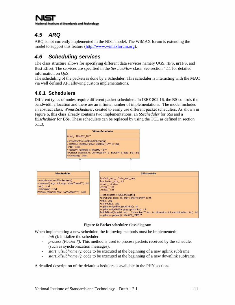
4.6 Scheduling services The class structure allows for specifying different data services namely UGS, rtPS, nrTPS, and
Best Effort. The services are specified in the ServiceFlow class. See section 4.11 for detailed
information on QoS.
The scheduling of the packets is done by a Scheduler. This scheduler is interacting with the MAC
via well defined API allowing custom implementations.
4.6.1 Schedulers
Different types of nodes require different packet schedulers. In IEEE 802.16, the BS controls the
bandwidth allocation and there are an infinite number of implementations. The model includes
an abstract class, WimaxScheduler, created to easily use different packet schedulers. As shown in
Figure 6, this class already contains two implementations, an SSscheduler for SSs and a
BSscheduler for BSs. These schedulers can be replaced by using the TCL as defined in section
6.1.3.
Figure 6: Packet scheduler class diagram
When implementing a new scheduler, the following methods must be implemented:
- init (): initialize the scheduler.
- process (Packet *): This method is used to process packets received by the scheduler
(such as synchronization messages).
- start_ulsubframe (): code to be executed at the beginning of a new uplink subframe.
- start_dlsubframe (): code to be executed at the beginning of a new downlink subframe.
A detailed description of the default schedulers is available in the PHY sections.

National Institute of Standards and Technology – Draft 1.2.1 - 12 -
4.6.2 TCL commands
$mac set-scheduler $scheduler
Set the MAC scheduler. It removes the previously assigned scheduler if present.
4.7 Bandwidth allocation and request mechanisms This section describes the implementation of the different mechanisms by which a SS can request
bandwidth.
4.7.1 Contention resolution
The BS allocates slots that are subject to collisions in the uplink direction. These slots are used in
two cases:
- Initial Ranging request
- Bandwidth request
The model supports a truncated binary exponential backoff for contention resolution. The UCD
messages broadcasted by the BS contain the window sizes (as a power-of-two value). The BS
also decides on the number of slots allocated in each frame.
Figure 7 shows the class structure used for contention resolution. An uplink subframe contains a
BwContentionslot and a RngContentionSlot. Both are subclasses of ContentionSlot which
provides the basic mechanisms related to contention.
During Network Entry, the SS performs ranging to adjust its transmission power. During this
step, the SS generates a RangingRequest. The SS picks a random backoff within the windows
provided by the BS and stores it. Then the SS decrements the counter every time a new
contention slot is found in the frame. When the counter reaches 0, the packet is being transmitted.

National Institute of Standards and Technology – Draft 1.2.1 - 13 -
Figure 7: Contention slots and contention requests
4.7.2 TCL commands
Mac/802_16 set rng_backoff_start_ 2
Mac/802_16 set rng_backoff_stop_ 6
Set the backoff window size for initial ranging requests
Mac/802_16 set bw_backoff_start_ 2
Mac/802_16 set bw_backoff_stop_ 6
Set the backoff window size for bandwidth requests

National Institute of Standards and Technology – Draft 1.2.1 - 14 -
Mac/802_16 set contention_rng_retry_ 16
Number of retransmission for sending ranging requests.
Mac/802_16 set request_retry_ 2
Number of retransmission for bandwidth requests
Note: the backoff windows are MAC parameters while the number of contention slots for ranging
and bandwidth is a BS scheduler parameter.
4.8 MAC support of PHY The model currently supports TDD. In this mode, uplink transmission occurs after downlink in
each frame.
The DL_MAP and UL_MAP messages sent every frame defines the burst allocation and
transmission opportunities for each station.
The information contained in the UL_MAP belongs to the same frame as shown in Figure 8.
Figure 8: Time relevance of DL_MAP and UL_MAP
4.9 Network entry and initialization When an SS wants to join a network it needs to perform network entry. As shown in Figure 9 the
model implements the following components of the network entry:
- Scan downlink channel
- Obtain transmit parameters
- Initial ranging
- Registration

National Institute of Standards and Technology – Draft 1.2.1 - 15 -
The following parameters can be configured:
- Timers to perform channel scanning
- Frequency of the DCD/UCD messages
- Parameters for initial ranging (backoff window size and number of slots per frame)
- Channel allocation
Some aspects are IEEE 802.16e are implemented therefore network entry can be reduced if the
SS has acquired the transmission parameters from the serving BS or during scanning (see section
4.12).
4.10 Ranging Ranging is a mechanism to allow a SS to maintain a good link quality by adjusting its
transmission power and modulation.
During the initial ranging, the SS includes the default DIUC profile to use for transmission. This
allows the simulation of nodes transmitting at different rates.
MS
Channel Selection
Normal operation
DL_MAP (Downlink map)
DCD (Downlink Channel Descriptor)
Ranging request
UCD (Uplink Channel Descriptor)
UL_MAP (Uplink map)
Downlink synchronization
Uplink synchronization
Ranging responseInitial ranging
Registration request
Registration responseRegistration
MS
Channel Selection
Normal operation
DL_MAP (Downlink map)
DCD (Downlink Channel Descriptor)
Ranging request
UCD (Uplink Channel Descriptor)
UL_MAP (Uplink map)
Downlink synchronization
Uplink synchronization
Ranging responseInitial ranging
Registration request
Registration responseRegistration
Figure 9: Network entry
National Institute of Standards and Technology – Draft 1.2.1 - 16 -
Currently there is no algorithm implemented to make use of the ranging capabilities. It is used to
add additional latency to the network entry. Periodic ranging and CDMA request are also not
implemented.
TCL command:
$mac set-diuc ProfileID ;# 1<= ProfileID <= 11
Set the profile to use by the MAC. The command is only valid at an MS.
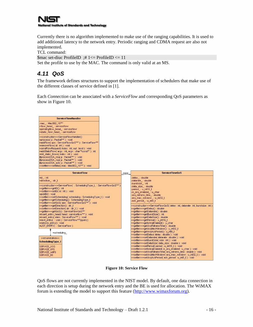
4.11 QoS The framework defines structures to support the implementation of schedulers that make use of
the different classes of service defined in [1].
Each Connection can be associated with a ServiceFlow and corresponding QoS parameters as
show in Figure 10.
Figure 10: Service Flow
QoS flows are not currently implemented in the NIST model. By default, one data connection in
each direction is setup during the network entry and the BE is used for allocation. The WiMAX
forum is extending the model to support this feature (http://www.wimaxforum.org).

National Institute of Standards and Technology – Draft 1.2.1 - 17 -
4.11.1 TCL commands
$mac set-servicehandler FlowHandler
Replace the default service flow handler.
4.12 MAC layer handover procedures The model supports layer 2 mobility. Depending on the configuration, the MS may perform
scanning and handover between BSs. This section presents the configuration parameters that
affect the handover capability.
4.12.1 Scanning
When the link quality deteriorates, the MS can send a MOB-SCN_REQ to the serving BS to
request scanning interval for the purpose of finding surrounding BSs. Figure 11 shows the
messages sequence during scanning as implemented in the model.
MS Serving BS Target BSNormal operation
Decision to search possible BSs
Normal operation
Listen to channels
Synchronization messages (DL_MAP,DCD, UCD, UL_MAP)
MOB-SCN_REQ
MOB-SCN_RSP
Scanning
Normal mode
Repeat scanning and normal mode intervals
MOB-SCN_REP
MOB-MSHO_REQ
MOB-MSHO_RSP
Switch channel and network entry
MOB-MSHO_IND
To trigger the sending of a MOB-SCN_REQ, the MS monitors the signal level of the incoming
packets. When the level crosses a threshold, the message is sent.
By default, the threshold is set to the RXThreshold therefore scanning is not used. To enable
scanning, change the lgd_factor_ attribute of the MIB to a value greater than 1.0. The higher the
value, the sooner the scanning will trigger.
During scanning, the MS collects RSSI values of incoming packets. These values are reported to
the serving BS that uses the information to select the best target BS.
Figure 11: Scanning procedure

National Institute of Standards and Technology – Draft 1.2.1 - 18 -
After the MS receives indication of the selected BS, it waits for a few frames before indicating its
intention to perform handover. The introduction of the delay is to allow the traffic buffered during
scanning to be exchanged before switching BSs.
Different scanning modes are implemented:
• In scan without association, the MS attempts to identify and synchronize with one or
more BSs. It also estimates the signal quality.
• In association level 0, the target BS has no information about the scanning MS and only
provides contention-based ranging allocations. After sending a ranging request, the MS
waits for a response from the BS with a default timeout value of 50ms.
• In association level 1, the serving BS negotiates with the target BSs a time at which the
MS will find a dedicated ranging region. After sending a ranging request, the MS waits
for a response from the BS with a default timeout value of 50ms.
Association level 2 is not currently implemented.
To allow these different scanning modes and to perform fast handovers, the WiMAXCtrlAgent is
required. The WiMAXCtrlAgent is an Agent performing 3 functions. The first one is to exchange
DCD/UCD information between the neighbor BSs. The second is to trigger the sending of NBR-
ADV messages to the MSs. The third one is to synchronize the serving BS and the target BSs
when performing scanning level 1 or 2. The messages are exchanged over wired links using
standard IP packets.
4.12.2 TCL commands
Mac/802_16 set lgd_factor_ factor ;# factor >= 1.0
Set the factor used to generate a link going down. When the received power is less that
factor*RXThresh_, a trigger is generated to initiate scanning. The higher the factor, the sooner
the trigger is generated.
Mac/802_16 set scan_duration_ 50
Set the number of frames to perform scanning.
Mac/802_16 set interleaving_interval_ 50
The number of frames interleaved between two scanning iterations.
Mac/802_16 set scan_iteration_ 2
Set the number of iterations to perform scanning.
Mac/802_16 set nbr_adv_interval_ 0.5 ;#in seconds
The interval time between two MOB_NBR-ADV messages
Mac/802_16 set scan_req_retry_ 3
Set the number of retransmission for MOB_SCAN-REQ
Agent/WimaxCtrl set debug_ 0 ;#set to 1 to print debug
Indicates if debug information must be printed regarding the scanning controller.
Agent/WimaxCtrl set adv_interval_ 1.0 ;# in seconds
Set the interval time between the exchanges of DCD/UCD information between neighboring BSs.
This exchange is done using the backbone network.

National Institute of Standards and Technology – Draft 1.2.1 - 19 -
Agent/WimaxCtrl set default_association_level_ 0
Set the scanning level to use. The information is embedded in the MOB_SCAN-RSP message
sent by the BS to the MS.
Agent/WimaxCtrl set synch_frame_delay_ 50 ;# in second
Processing delay between the reception of a MOB_SCAN-REQ and the sending of the
MOB_SCAN-RSP when synchronization with target BSs is needed.
4.13 Frame structure
Figure 12: Frame class diagram
The design used to represent a frame is closely similar to the structure defined in IEEE 802.16 for
TDD. A frame (class FrameMap) contains a downlink and an uplink subframe (abstract class
SubFrame, class DlSubFrame and UlSubFrame). The subframes are themselves seperated into
PHY PDU intervals. In each of these intervals, bandwidth is allocated in burst (abstract class
Burst, class UlBurst and class DlBurst) for the different stations. Each of these bursts can have a
different modulation and frequency called profile (class Profile).
Normally the BS allocates bandwidth for a station to transmit its data. In some cases, generally
initial ranging and bandwidth requests, the SSs need to compete with each other to access the
medium. These intervals (class ContentionSlot) are only present in the uplink since the BS has
total control over the downlink traffic.
The FrameMap class also contains methods to extract and parse the control messages. At the BS,
the scheduler creates the map structure according to an allocation algorithm, and then calls the
functions getDL_MAP, getUL_MAP, getDCD, and getUCD, to retrieve the packets containing the
necessary information to be sent to the SSs. At the SS, the scheduler calls the reverse functions
parseDL_MAP, parseUL_MAP, parseDCD, and parseUCD to recreate the datastructure
necessary to handle proper reception and transmission of packets.

National Institute of Standards and Technology – Draft 1.2.1 - 20 -
4.14 Packet processing Figure 4 shows the packet flows for incoming and outgoing packets.
The activity diagrams (Figure 14 to Figure 16) provide more detailed information on how the
packets cross the MAC layer.
Figure 14: Outgoing packet processing
A packet received from an upper layer is classified using the registered classifiers. Since there
may be multiple classifiers, the MAC accesses them one by one trying until a valid CID is found,
OFDM Physical layer
Upper layer protocols
Classifiers
Frame reassembly
Outgoing queues with
fragmentation per CID
Service Flow Handler
Service flows
Scheduler
STA: process synchronization
messages from BS. Schedule uplink
traffic.
BS: generate synchronization
messages and schedule downlink
traffic. Also perform admission
control.
DSx frames
Synchronization
Messages
DSx frames
Synchronization
Messages
Controls
frame
transmission
Outgoing packet
Incoming packetOFDM Physical layer
Upper layer protocols
Classifiers
Frame reassembly
Outgoing queues with
fragmentation per CID
Outgoing queues with
fragmentation per CID
Service Flow Handler
Service flows
Service Flow Handler
Service flows
Scheduler
STA: process synchronization
messages from BS. Schedule uplink
traffic.
BS: generate synchronization
messages and schedule downlink
traffic. Also perform admission
control.
DSx frames
Synchronization
Messages
DSx frames
Synchronization
Messages
Controls
frame
transmission
Outgoing packet
Incoming packet
Figure 13: Packet processing overview
National Institute of Standards and Technology – Draft 1.2.1 - 21 -
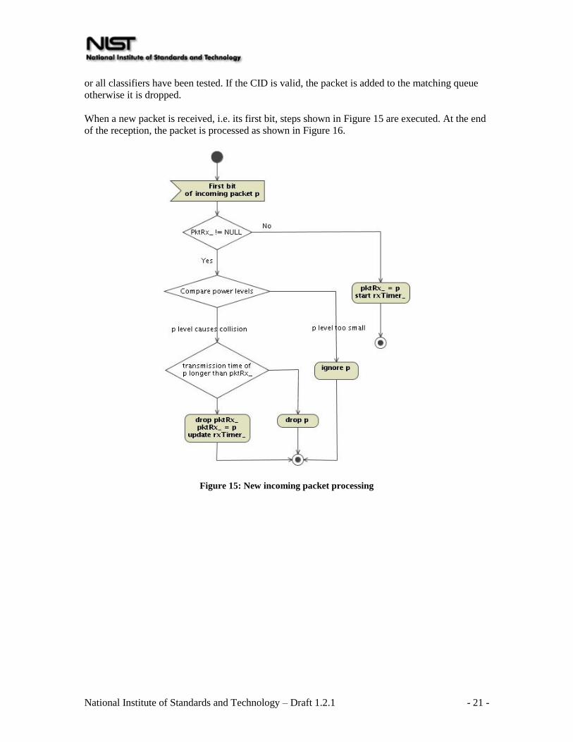
or all classifiers have been tested. If the CID is valid, the packet is added to the matching queue
otherwise it is dropped.
When a new packet is received, i.e. its first bit, steps shown in Figure 15 are executed. At the end
of the reception, the packet is processed as shown in Figure 16.
Figure 15: New incoming packet processing

National Institute of Standards and Technology – Draft 1.2.1 - 22 -
Figure 16: received packet processing

National Institute of Standards and Technology – Draft 1.2.1 - 23 -
5 PHY
5.1 OFDM PHY
5.1.1 OFDM physical layer class diagram
Figure 17: OFDM Physical layer class diagram
The OFDM physical layer is used to transmit packets in the implemented model. The
configuration is done using TCL bindings for the frequency bandwidth and cyclic prefix. Since it
inherits from the WirelessPhy class, attributes such as frequency or transmission power can also
be configured by TCL.
As Shown in Figure 17, the physical layer can be in different states. When in sending mode, all
incoming packets are discarded. In receiving mode, packets cannot be sent. Furthermore, the
packet header contains virtual information, such as frequency, modulation, and cyclic prefix,
which are used to filter incoming packets.
The model supports different modulations. The MAC layer allocates bursts that can use different
modulations according to distance or interference. This affects the data rate and transmission
time. The physical layer includes helper functions called by the MAC layers when transmitting
data:
- getTrxTime returns the time required to send a packet given its size and modulation.
- getMaxPktSize is the reverse function and returns the maximum packet size given the
number of OFDM symbols available and the modulation used.
The node_on and node_off functions enable or disable blocking all transmissions and receptions
of packets, but is not currently linked to any power consumption mechanisms.

National Institute of Standards and Technology – Draft 1.2.1 - 24 -
5.1.2 OFDM Packet schedulers
5.1.2.1 BSscheduler
The current implementation of the packet scheduler for BS can be configured using the following
commands:
set scheduler [new WimaxScheduler/BS]
Creates a packet scheduler for BS.
$scheduler set-contention-size $size
Set the number of contention slots to be allocated for initial ranging and bandwidth requests in
each frame.
The scheduler implements a Best-Effort scheduler coupled with a Round Robin algorithm to
distribute the bandwidth allocations among the users.
To support BE, bandwidth requests are generated at the SS indicating the amount of data to
transfer.
The ratio between the downlink and uplink subframes is fixed and is configured via TCL
WimaxScheduler/BS set dlratio_ 0.3
Indicates 30% of the frame is for downlink and 70% is for uplink.
The scheduler also allows users to have different modulations.
$scheduler set-default-modulation $modulation
sets the modulation to use for the initial ranging and bandwidth requests slots.
Profile bursts are created by default as follows:
Profile name Modulation
DIUC_PROFILE_1, UIUC_PROFILE_1 OFDM_BPSK_1_2
DIUC_PROFILE_2, UIUC_PROFILE_2 OFDM_QPSK_1_2
DIUC_PROFILE_3, UIUC_PROFILE_3 OFDM_QPSK_3_4
DIUC_PROFILE_4, UIUC_PROFILE_4 OFDM_16QAM_1_2
DIUC_PROFILE_5, UIUC_PROFILE_5 OFDM_16QAM_3_4
DIUC_PROFILE_6, UIUC_PROFILE_6 OFDM_64QAM_2_3
DIUC_PROFILE_7, UIUC_PROFILE_7 OFDM_64QAM_3_4
The user can select the burst profile to use [1-7] by TCL using the following:
[$SSWithWiMax set mac_(0)] set-diuc 7
Note: By default, the profile (modulation) is the same for BOTH downlink and uplink for
communication between a SS and a BS.
5.1.2.2 SSscheduler
set scheduler [new WimaxScheduler/SS]
Creates a packet scheduler for SS.
5.1.3 TCL Configuration
Phy/WirelessPhy/OFDM set g_ 0 ;# cyclic prefix

National Institute of Standards and Technology – Draft 1.2.1 - 25 -
Set the cyclic prefix to use. Valid values are 0.25 (1/4), 0.125 (1/8), 0.0625 (1/16), 0.03125 (1/32)
By increasing the cyclic prefix, the overhead is increasing thus reducing the maximum
throughput.
Mac/802_16 set fbandwidth_ 5e+6 ;# frequency bandwidth (MHz)
Configure the frequency bandwidth. Setting a higher bandwidth increases the throughput.
Mac/802_16 set rtg_ 10 ;# number of PS to switch from receiving to transmitting
state
The duration required to switch from receiving to transmitting. Increasing the value decreases the
maximum achievable throughput.
Mac/802_16 set ttg_ 10 ;# number of PS to switch from transmitting to receiving
state
The duration required to switch from transmitting to receiving. Increasing the value decreases the
maximum achievable throughput.
Mac/802_16 set channel_ 0 ;# channel number
Se the channel to use. This is configured at the MAC and passed to the physical layer. It is
required to set it at the BS. The MS will scan the channels to detect surrounding BSs.
5.2 OFDMA PHY OFDMA physical layer is not currently implemented in the NIST model. The WiMAX forum is
extending the model to support this feature (http://www.wimaxforum.org).
6 Configuration
6.1 Setup There are multiple steps required to start using the IEEE 802.16 model in the simulations.
6.1.1 Configure the node
The MAC and Physical layers are specified using the node-config method in TCL:
$BSWithWiMax node-config
-macType Mac/802_16/BS
-phyType Phy/WirelessPhy/OFDM
$SSWithWiMax node-config
-macType Mac/802_16/SS
-phyType Phy/WirelessPhy/OFDM
6.1.2 Configure a packet classifier
In IEEE 802.16, packets received by the MAC layer from upper layers are classified in order to
direct them to the proper connection. The model proposes a classifier based on the destination
MAC address and packet type.
# Create classifier

National Institute of Standards and Technology – Draft 1.2.1 - 26 -
set classifier [new SDUClassifier/Dest]
# Set the classifier priority
$classifer set-priority 1
# Retrieve the MAC layer and delete all registered classifiers
[$nodeWithWiMax set mac_(0)] reset-classifiers
# Retrieve the MAC layer and set classifier
[$nodeWithWiMax set mac_(0)] add-classifier $classifier
Note: A default classifier (DestClassifier) is added to the MAC. To add change the classier, reset
the list and add a new classifier.
6.1.3 Configure a scheduler
To allow flexibility the MAC layer can use different types of schedulers. Mainly there is one for
Base Stations (BSs) and one for Subscriber Stations (SSs). Section 4.6.1 shows how to extend the
default schedulers.
For BS, the following TCL code sets the scheduler
# Create scheduler
set scheduler [new WimaxScheduler/BS]
# Add scheduler
[$nodeWithWiMax set mac_(0)] set-scheduler $scheduler
Note: This scheduler is automatically created when the MAC 802.16 BS is created.
For SS, the following needs to be used
# Create scheduler
set scheduler [new WimaxScheduler/SS]
# Add scheduler
[$nodeWithWiMax set mac_(0)] set-scheduler $scheduler
Note: This scheduler is now automatically created when the MAC 802.16 SS is created.
6.1.4 Configure the channel
To allow multi cell topologies, the MAC layers can operate at different frequencies. To set the
frequencies, the user can set the channel number for the MAC.
# Retrieve the MAC layer and set classifier
[$nodeWithWiMax set mac_(0)] set-channel 1 #valid 0-4
The current frequency table contains 5 channels on the 3.5GHz band and 7MHz frequency
bandwidth.
6.2 Statistics Some statistics are collected at the MAC layer. The following command is used to display their
values during the simulation.
Mac/802_16 set print_stats_ true

National Institute of Standards and Technology – Draft 1.2.1 - 27 -
6.3 Tracing The IEEE 802.16 model introduces new values in the trace file. Two new reasons for dropping a
packet appear:
- CID: this reason code is used when a packet received at the MAC layer cannot be
matched to any connection.
- QWI: each connection has a queue to store pending frames. When the queue is full, the
packet is dropped using this reason code.
- FRG: indicates an error during the transmission of a fragment.
A new packet type is introduced. Sometimes, BSs need to communicate for synchronization
purposes. A new agent called Agent/WimaxCtrl handles this communication, and sends packets
marked as WimaxCtrl.
Note on traces when fragmentation is used:
If MAC traces are enabled and fragmentation is used, the fragments will be shown as sent but not
received. At the last fragment, the complete packet can be decoded and passed to upper layer
which would then create a trace entry on the receiver side. For example, let’s consider a packet
with 1520 bytes which will be fragmented in four fragments of 396, 396, 396, and 364 bytes. The
trace file will contain four “send” entries for each of the fragments but only one “received” entry
of 1520 bytes for the complete packet.
7 Parameters and Constants
7.1 Parameters Many parameters exist to configure the MAC and Physical layers. Below is the list of parameters,
default values, and descriptions as presented in the file ns-wimax.tcl.
# This class contains default value for tcl
#Physical layer configuration
Phy/WirelessPhy/OFDM set g_ 0 ;# cyclic prefix
Mac/802_16 set channel_ 0 ;# channel number
Mac/802_16 set fbandwidth_ 5e+6 ;# frequency bandwidth (MHz)
Mac/802_16 set rtg_ 10 ;# number of PS to switch from receiving to
transmitting state
Mac/802_16 set ttg_ 10 ;# number of PS to switch from transmitting to
receiving state
#MAC layer configuration
Mac/802_16 set queue_length_ 50 ;#maximum number of packets
Mac/802_16 set frame_duration_ 0.004 ;# frame duration (s)
Mac/802_16 set dcd_interval_ 5 ;# interval between the broadcast of DCD
messages (max 10s)
Mac/802_16 set ucd_interval_ 5 ;# interval between the broadcast of UCD
messages (max 10s)
Mac/802_16 set init_rng_interval_ 1 ;# time between initial ranging regions
assigned by the BS (max 2s). Note used
Mac/802_16 set lost_dlmap_interval_ 0.6 ;# timeout value for receiving DL_MAP message
(s)
Mac/802_16 set lost_ulmap_interval_ 0.6 ;# timeout value for receiving UL_MAP message
(s)
#Timers (all values in seconds)
Mac/802_16 set t1_timeout_ [expr 5* [Mac/802_16 set dcd_interval_]] ;#
wait for DCD timeout
Mac/802_16 set t2_timeout_ [expr 5* [Mac/802_16 set init_rng_interval_]] ;#

National Institute of Standards and Technology – Draft 1.2.1 - 28 -
wait for broadcast ranging timeout
Mac/802_16 set t3_timeout_ 0.2 ;#
ranging response timeout
Mac/802_16 set t6_timeout_ 3 ;#
registration response timeout
Mac/802_16 set t12_timeout_ [expr 5* [Mac/802_16 set ucd_interval_]] ;# UCD
descriptor timeout
Mac/802_16 set t16_timeout_ 0.1 ;#
bandwidth request timeout
Mac/802_16 set t17_timeout_ 5 ;#
authentication. Not used
Mac/802_16 set t21_timeout_ 0.02 ;#
wait for DL_MAP timeout. Replace with 20ms to emulate preamble scanning on channel.
Mac/802_16 set contention_rng_retry_ 16 ;# number of retries on ranging requests
(contention mode)
Mac/802_16 set invited_rng_retry_ 16 ;# number of retries on ranging requests
(invited mode)
Mac/802_16 set request_retry_ 16 ;# number of retries on bandwidth allocation
requests
Mac/802_16 set reg_req_retry_ 3 ;# number of retries on registration requests
Mac/802_16 set tproc_ 0.001 ;# time between arrival of last bit of a
UL_MAP and effectiveness. Note used
Mac/802_16 set dsx_req_retry_ 3 ;# number of retries on DSx requests
Mac/802_16 set dsx_rsp_retry_ 3 ;# number of retries on DSx responses
Mac/802_16 set rng_backoff_start_ 2 ;# initial backoff window size for ranging
requests
Mac/802_16 set rng_backoff_stop_ 6 ;# maximal backoff window size for ranging
requests
Mac/802_16 set bw_backoff_start_ 2 ;# initial backoff window size for bandwidth
requests
Mac/802_16 set bw_backoff_stop_ 6 ;# maximal backoff window size for bandwitdh
requests
Mac/802_16 set scan_duration_ 50 ;# duration (in frames) of scan interval
Mac/802_16 set interleaving_interval_ 50 ;# duration (in frames) of interleaving
interval
Mac/802_16 set scan_iteration_ 2 ;# number of scan iterations
Mac/802_16 set t44_timeout_ 0.1 ;# timeout value for scan requests (s)
Mac/802_16 set scan_req_retry_ 5 ;# number of retries on scan requests
Mac/802_16 set max_dir_scan_time_ 0.2 ;# max scan for each neighbor BSs (s)
Mac/802_16 set nbr_adv_interval_ 0.5 ;# interval between 2 MOB-NBR_ADV messages (s)
Mac/802_16 set client_timeout_ 0.5 ;# timeout value for detecting out of range
client
Mac/802_16 set lgd_factor_ 1 ;# coefficient used to trigger Link Going Down
(1 for no trigger)
Mac/802_16 set print_stats_ false ;# true to activate print of statistics
Mac/802_16 set rxp_avg_alpha_ 1 ;# coefficient for statistic on receiving
power
Mac/802_16 set delay_avg_alpha_ 1 ;# coefficient for statistic on frame delay
Mac/802_16 set jitter_avg_alpha_ 1 ;# coefficient for statistic on frame jitter
Mac/802_16 set loss_avg_alpha_ 1 ;# coefficient for statistic on frame loss
Mac/802_16 set throughput_avg_alpha_ 1 ;# coefficient for statistic on throughput
Mac/802_16 set throughput_delay_ 0.02 ;# interval time to update throughput when
there is no traffic
WimaxScheduler/BS set dlratio_ 0.3 ;#default DL/UL subframe ratio
8 Annexes
8.1 Current known issues Pb when changing channel bandwidth
National Institute of Standards and Technology – Draft 1.2.1 - 29 -
8.2 FAQ Q: What does "bash: ns: command not found" mean?
A: The NS-2 simulator is not properly installed/compiled. Execute "./configure; make clean;
make" from the ns-2.29 directory.
Q: What does invalid command name "Phy/WirelessPhy/OFDM" while executing
"Phy/WirelessPhy/OFDM set g_0" mean?
A: The OFDM class is unknown to NS. This means the code has not been recompiled. Execute
"./configure; make clean; make" from the ns-2.29 directory.
Q: What does invalid command name "Mac/802_16" while executing "Mac/802_16 set debug_
0" mean?
A: The Mac/802_16 class is unknown to NS. This means the code has not been recompiled.
Execute "./configure; make clean; make" from the ns-2.29 directory.
Q: Does the current model support class of service (UGS, RTPS, NRTPS and BE)?
A: No. Though the architecture defines the structures to use it, the current scheduler does not
make use of it.
Q: What scheduler is implemented?
A: The default scheduler for OFDM uses a Best Effort algorithm coupled with the Round Robin.
Q: How to set the -DDEBUG_WIMAX switch?
A: Look for the line starting with "DEFINE = -DTCP_DELAY_BIND_ALL" and add the -
DDEBUG_WIMAX.
Q: How to set the datarate?
A: Unlike the 802.11 implementation, the datarate is not something set in TCL. Since each burst
can use a different modulation and therefore have different datarates, we opted for a dynamic
calculation of the datarate. By setting the frequency bandwidth, cyclic prefix and the modulation,
the datarate will change. Other parameters such as number of contention slots for initial ranging
and bandwidth requests or the downlink/uplink ratio affect the maximum amount of data that can
be transferred during a frame.
9 References
IEEE Std 802.16-2004: IEEE Standard for Local and metropolitan area networks. Part 16: Air
Interface for Fixed Broadband Wireless Access Systems
Ieee Std 802.16e-2005: IEEE Standard for Local and metropolitan area networks. Part 16: Air
Interface for Fixed and Mobile Broadband Wireless Access Systems. Amendment 2: Physical and
Medium Access Control Layers for Combined Fixed and Mobile Operation in Licensed Bands
and Corrigendum 1


