Wilo-EMU KM1300 + NU911productfinder-wilo.cdn.mediamid.com/pfcdndoc/wilo_f_020000140001e...Wilo-EMU...
67
Wilo-EMU KM1300... + NU911... Installation and operating instructions Order no.: serial no. template TMPRWLEER
Transcript of Wilo-EMU KM1300 + NU911productfinder-wilo.cdn.mediamid.com/pfcdndoc/wilo_f_020000140001e...Wilo-EMU...
Wilo-EMU KM1300... + NU911...
Installation and operating instructions
Order no.:
serial no.
template
TMPRWLEER

WILO EMU GmbHHeimgartenstr. 195030 Hof
330995003 Hof
Telefon: +49 9281 974-0Telefax: +49 9281 96528Email: [email protected]: www.wiloemu.com
E:\shares\Baprod\BA\subtec_m\cleanwater\us\title-wilo.fm WILO EMU 3.0
E:\shares\Baprod\BA\subtec_m\general\us\content.fm 0-1
Table of Contents
1 Introduction 1-1
Preface 1-1Structure of the manual 1-1Personnel qualification 1-1Illustrations 1-1Copyright 1-1Abbreviations and technical terms 1-1Manufacturer's address 1-3Rights of alteration 1-3
2 Safety 2-1
Instructions and safety information 2-1Guidelines used and CE certification 2-2General safety 2-2Electrical work 2-2Electrical connection 2-3Ground connection 2-3Operating procedure 2-3Safety and control devices 2-3Operation in an explosive atmosphere 2-4Sound pressure 2-4Pumped fluids 2-4Warranty 2-5
3 Product description 3-1
General product information 3-1Proper use and fields of application 3-1Conditions of use 3-1Construction 3-1Cooling 3-3Type designation 3-3Name plate 3-3Technical data 3-4
4 Transport and storage 4-1
Delivery 4-1Transport 4-1Storage 4-1Returning to the supplier 4-2

0-2 WILO EMU 3.0
5 Installation 5-1
Installation types 5-1The operating area 5-1Assembly accessories 5-1Installation 5-5Removal 5-11
5-11
6 Startup 6-1
Preparatory measures 6-1Electrical system 6-2Direction of rotation 6-2Motor protection and activation types 6-2After starting 6-3
7 Maintenance 7-1
Lubricants 7-1Glycol Overview 7-2Maintenance intervals 7-2Maintenance tasks 7-3
7-4
8 Shutdown 8-1
Temporary shutdown 8-1Final shutdown / storage 8-1Restarting after an extended period of storage 8-1
8-2
9 Troubleshooting 9-1
Fault: The machine will not start 9-1Fault: The motor starts, but the motor protection switch triggers shortly after start-up 9-1Fault: Machine runs but does not pump 9-2Fault: The machine runs, but not at the stated operating levels 9-2Fault: The machine does not run smoothly and is noisy 9-3Fault: Mechanical shaft seal leaks, sealing chamber monitor reports fault and switches the machine off 9-3Further steps for troubleshooting 9-4
A List of machine operators and maintenance A-1
List of machine operators A-1Maintenance and inspection log A-2

E:\shares\Baprod\BA\subtec_m\general\us\content.fm 0-3
B Operation with a static frequency converter B-1
Selecting the motor and converter B-1Minimum speed for submersible pumps (well pumps) B-1Minimum speed for waste water and sewage pumps B-1Operation B-1Max. voltage peaks and rise speed B-1EMC B-2Motor protection B-2Operation up to 60 Hz B-2Efficiency B-2Summary B-2
C Anti-vortex plate C-1
General product information C-1Installation C-1
D Instructions on filling the NU 611 and NU 811 motors D-1
General product information D-1Special characteristics D-1Motor filling fluid D-1
E Use as a sprinkle pump E-1
Proper use and fields of application E-1Approved units E-1Features of sprinkler pumps E-1Technical data E-1Signs used E-1
F Data Sheet - Electrical Connection F-1
Safety notes F-1Insulation resistance F-1Monitoring equipment F-1Wire designation of the connection lead F-2
G EC declaration of conformity G-1


Introduction
E:\shares\Baprod\BA\subtec_m\general\us\introduction.fm 1-1
1 Introduction
PrefaceDear Customer,
Thank you for choosing one of our company’s products. You have purchased a product which hasbeen manufactured to the latest technical standards. Read this operating and maintenance manualcarefully before you first use it. This is the only way to ensure that the product is safely and eco-nomically used.
The documentation contains all the necessary specifications for the product, allowing you to use itproperly. In addition, you will also find information on how to recognize potential dangers, reducerepair costs and downtime, and increase the reliability and working life of the product.
All safety requirements and specific manufacturer’s requirements must be fulfilled before the prod-uct is put into operation. This operating and maintenance manual supplements any existingnational regulations on industrial safety and accident prevention. This manual must also be acces-sible to personnel at all times and also be made available where the product is used.
Structure of the manualThe manual is divided into several chapters. Each chapter has a clear heading which tells you what itdescribes.
The numbered chapters correspond to the standard chapters for a product. They contain all thedetailed information on your product.
Chapters numbered alphabetically are added for specific customers. They contain informationincluding the selected accessories, special coatings, connection diagrams and the declaration ofconformity.
The table of contents also acts as a brief reference, because all the important sections are givenheaders. The header of each section is in the outside column, so that you can find everything, evenwhen skimming through the manual.
All important operating and safety instructions are highlighted. You can find detailed informationon the structure of these texts in chapter 2, “Safety”.
Personnel qualificationAll personnel who work on or with the product must be qualified for such work; electrical work, forexample may only be carried out by a qualified electrician. The entire personnel must be of age.
Operating and maintenance staff must also work according to local accident prevention regula-tions.
It must be ensured that personnel have read and understood the instructions in this operating andmaintenance handbook; if necessary this manual must be ordered from the manufacturer in therequired language.
IllustrationsThe illustrations used are of dummies and original drawings of the products. This is the only realis-tic solution for our wide range of products and the differing sizes enabled by the modular system.More exact drawings and specifications can be found on the dimension sheet, the planning infor-mation and/or the installation plan.
CopyrightThis operation and maintenance manual has been copyrighted by the manufacturer. The operationand maintenance handbook is intended for the use by assembly, operating and maintenance per-sonnel. It contains technical specifications and diagrams which may not be reproduced or distrib-uted, either completely or in part, or used for any other purpose without the expressed consent ofthe manufacturer.
Abbreviations and technical terms
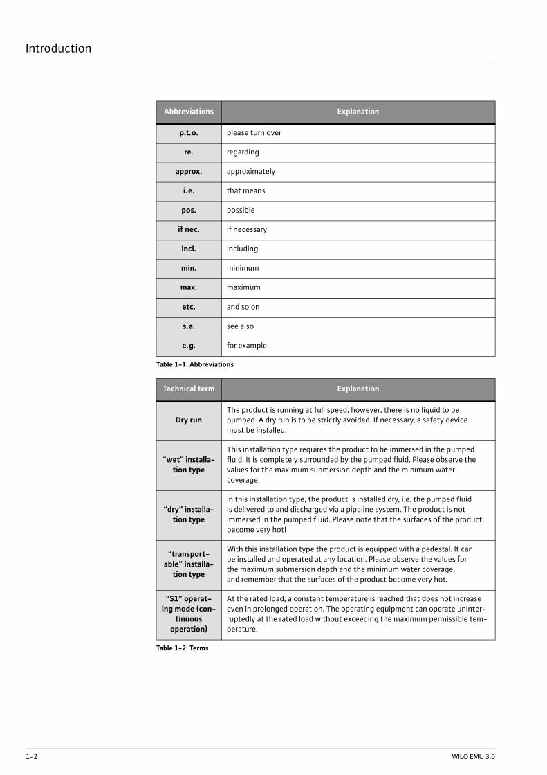
Various abbreviations and technical terms are used in this operating and maintenance manual.Table 1 contains all the abbreviations, and Table 2 all the technical terms.
Introduction
1-2 WILO EMU 3.0
Abbreviations Explanation
p.t.o. please turn over
re. regarding
approx. approximately
i.e. that means
pos. possible
if nec. if necessary
incl. including
min. minimum
max. maximum
etc. and so on
s.a. see also
e.g. for example
Table 1-1: Abbreviations
Technical term Explanation
Dry runThe product is running at full speed, however, there is no liquid to be pumped. A dry run is to be strictly avoided. If necessary, a safety device must be installed.
“wet” installa-tion type
This installation type requires the product to be immersed in the pumped fluid. It is completely surrounded by the pumped fluid. Please observe the values for the maximum submersion depth and the minimum water coverage.
“dry” installa-tion type
In this installation type, the product is installed dry, i.e. the pumped fluid is delivered to and discharged via a pipeline system. The product is not immersed in the pumped fluid. Please note that the surfaces of the product become very hot!
“transport-able” installa-
tion type
With this installation type the product is equipped with a pedestal. It can be installed and operated at any location. Please observe the values for the maximum submersion depth and the minimum water coverage, and remember that the surfaces of the product become very hot.
“S1” operat-ing mode (con-
tinuous operation)
At the rated load, a constant temperature is reached that does not increase even in prolonged operation. The operating equipment can operate uninter-ruptedly at the rated load without exceeding the maximum permissible tem-perature.
Table 1-2: Terms

Introduction
E:\shares\Baprod\BA\subtec_m\general\us\introduction.fm 1-3
Manufacturer's addressWILO EMU GmbHHeimgartenstr. 1DE - 95030 HofTel.: +49 9281 974-0Fax: +49 9281 96528Internet: www.wiloemu.comE - mail: [email protected]
Rights of alterationThe manufacturer reserves the right to make technical alterations to systems or components. Thisoperating and maintenance manual refers to the product indicated on the title page.
“S2” operat-ing mode
(short-term operation)
The period of service at the rated load is short in comparison to the subse-quent pause. The maximum operating period is indicated in minutes, for example, S2-15. The operating equipment can operate during this time uninterruptedly at the rated load without exceeding the maximum permissi-ble temperature. The pauses must continue until the machine temperature no longer exceeds that of the coolant by more than 2K .
“Siphoning operation”
Siphoning operation is similar to dry running. The product operates at full speed, but only small amounts of liquid are pumped. Siphoning operation is only possible with certain types; see the “Product description” chapter.
Dry-run pro-tection
The dry-run protection is designed to automatically shut down the product if the water level falls below the minimum water coverage value of the product. This is made possible by installing a float switch.
Level control The level control is designed to switch the product on or off depending on the filling level. This is made possible by installing a float switch.
Technical term Explanation
Table 1-2: Terms


Safety
E:\shares\Baprod\BA\subtec_m\general\us\security.fm 2-1
2 SafetyThis chapter lists all the generally applicable safety instructions and technical information. Further-more, every other chapter contains specific safety instructions and technical information. Allinstructions and information must be observed and followed during the various phases of the prod-uct's lifecycle (installation, operation, maintenance, transport etc.). The operator is responsible forensuring that personnel follow these instructions and guidelines.
Instructions and safety information
This manual uses instructions and safety information for preventing injury and damage to property.To make this clear for the personnel, the instructions and safety information are distinguished asfollows:
InstructionsInstructions are indented by 10 mm and printed in 10pt bold script. Instructions contain text refer-ring to previous text or particular sections of chapters, or highlight brief instructions. Example:
For machines approved for work in explosion zones, please refer to the“Explosion protection in accordance with the .... regulation” chapter.
Safety informationSafety information is indented by 5 mm and printed in 12pt bold script. Information only referringto damage to property is printed in gray.
Information referring to personal injury is printed in black and always accompanied by a dangersymbol. Danger, prohibition or instruction symbols are used as safety symbols. Example:
The safety symbols conform to the generally valid guidelines and regulations, for example DIN andANSI.
Each safety instruction begins with one of the following signal words:
Safety instructions begin with a signal word and description of the hazard, followed by the hazardsource and potential consequences, and end with information on preventing it.
Example:
Beware of rotating parts!The moving rotor can crush and sever limbs. Switch off themachine and let the rotor come to a rest.
Danger sym-bol: general
hazard
Danger sym-bol, e.g. elec-trical current
Prohibition symbol, e.g.
keep out
Instruction symbol, e.g.
wear protec-tive clothing
Signal word Meaning
Danger Serious or fatal injuries can occur.
Warning Serious injuries can occur.
Caution Injuries can occur.
Caution(Instruction
without symbol)
Serious damage to property can occur, including irreparable damage.
Table 2-1: Signal words and what they mean

Safety
2-2 WILO EMU 3.0
Guidelines used and CE certification
Our products are subject to
- various EC directives
- various harmonized standards
- various national standards.
Please consult the EU Declaration of Conformity for the precise information and the guidelines andnorms in effect. The EU Declaration of Conformity is issued in accordance with EU Directive 98/37/EC, Appendix II A.
Also, various national standards are also used as a basis for using, assembling and dismantling theproduct. These include the German accident prevention regulations, VDE regulations, GermanEquipment Safety Law etc.
The CE symbol is found either on the type plate or next to the type plate. The type plate is attachedto the motor casing or to the frame.
General safety - Never work alone when installing or removing the product.
- The machine must always be switched off before any work is performed on it (assembly, dis-mantling, maintenance, installation). The product must be disconnected from the electricalsystem and secured against being switched on again. All rotating parts must be at a standstill.
- The operator should inform his/her superior immediately should any defects or irregularitiesoccur.
- It is of vital importance that the system is shut down immediately by the operator if anyproblems arise which may endanger safety of personnel. Problems of this kind include:- Failure of the safety and/or control devices- Damage to critical parts- Damage to electric installations, cables and insulation
- Tools and other objects should be kept in a place reserved for them so that they can be foundquickly.
- Sufficient ventilation must be provided in enclosed rooms.
- When welding or working with electronic devices, ensure that there is no danger of explosion.
- Only use fastening devices which are legally defined as such and officially approved.
- The fastening devices should be suitable for the conditions of use (weather, hooking system,load, etc). If these are separated from the machine after use, they should be expressly markedas fastening devices. Otherwise they should be carefully stored.
- Mobile working apparatus for lifting loads should be used in a manner that ensures the stabil-ity of the working apparatus during operation.
- When using mobile working apparatus for lifting non-guided loads, measures should be takento avoid tipping and sliding etc.
- Measures should be taken that no person is ever directly beneath a suspended load. Further-more, it is also prohibited to move suspended loads over workplaces where people arepresent.
- If mobile working equipment is used for lifting loads, a second person should be present tocoordinate the procedure if needed (for example if the operator's field of vision is blocked).
- The load to be lifted must be transported in such a manner that nobody can be injured in thecase of a power cut. Additionally, when working outdoors, such procedures must be inter-rupted immediately if weather conditions worsen.
These instructions must be strictly observed. Non-observance can resultin injury or serious damage to property.
Electrical work Our electrical products are operated with alternating or industrial high-voltage current. The localregulations (e.g. VDE 0100) must be adhered to. The “Electrical connection” data sheet must beobserved when connecting the product. The technical specifications must be strictly adhered to.
If the machine has been switched off by a protective device, it must notbe switched on again until the error has been corrected.

Safety
E:\shares\Baprod\BA\subtec_m\general\us\security.fm 2-3
Electrical connectionThe operator is required to know where the machine is supplied with current and how to cut off thesupply.
When the machine is connected to the electrical control panel, especially when electronic devicessuch as soft startup control or frequency drives are used, the relay manufacturer's specificationsmust be followed in order to conform to EMC. Special separate shielding measures e.g. specialcables may be necessary for the power supply and control cables.
The connections may only be made if the relays meet the harmonized EUstandards. Mobile radio equipment may cause malfunctions.
Ground connectionOur products (machine including protective devices and operating position, auxiliary hoisting gear)must always be grounded. If there is a possibility that people can come into contact with themachine and the pumped liquid (e.g. at construction sites), the grounded connection must be addi-tionally equipped with a fault current protection device.
The electrical products conform to motor protection class IP 68 in accor-dance with the valid norms.
Operating procedureWhen operating the product, always follow the locally applicable laws and regulations for worksafety, accident prevention and handling electrical machinery. To help to ensure safe working prac-tice, the responsibilities of employees should be clearly set out by the owner. All personnel areresponsible for ensuring that regulations are observed.
Certain parts such as the rotor and propeller rotate during operation in order to pump the fluid. Cer-tain materials can cause very sharp edges on these parts.
Safety and control devices
Our products are equipped with various safety and control devices. These include, for example suc-tion strainers, thermo sensors, sealed room monitor etc. These devices must never be dismantledor disabled.
Equipment such as thermo sensors, float switches, etc. must be checked by an electrician forproper functioning before start-up (see the “Electrical Connection” data sheet). Please remember
Beware of electrical currentIncorrectly performed electrical work can result in fatal injury!This work may only be carried out by a qualified electrician.
Beware of dampMoisture penetrating cables can damage them and render themuseless. Never immerse cable ends in the pumped fluid or otherliquids. Any unused wires must be disconnected.
Beware of electromagnetic radiationElectromagnetic radiation can pose a fatal risk for people withpacemakers. Put up appropriate signs and make sure anyoneaffected is aware of the danger.
Beware of rotating partsThe moving parts can crush and sever limbs. Never reach into thepump unit or the moving parts during operation. Switch off themachine and let the moving parts come to a rest before mainte-nance or repair work.
Safety
2-4 WILO EMU 3.0
that certain equipment requires a relay to function properly, e.g. posistor and PT100 sensor. Thisrelay can be obtained from the manufacturer or a specialist electronics dealer.
Staff must be informed of the installations used and how they work.
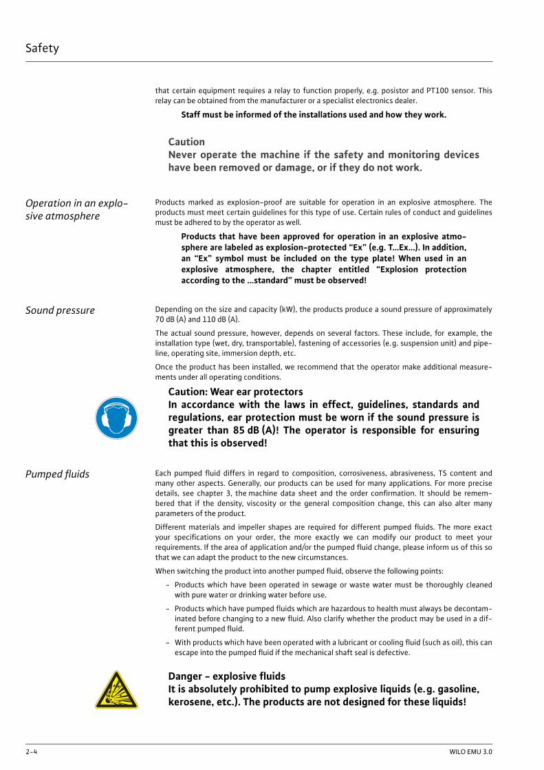
Operation in an explo-sive atmosphere
Products marked as explosion-proof are suitable for operation in an explosive atmosphere. Theproducts must meet certain guidelines for this type of use. Certain rules of conduct and guidelinesmust be adhered to by the operator as well.
Products that have been approved for operation in an explosive atmo-sphere are labeled as explosion-protected “Ex” (e.g. T…Ex…). In addition,an “Ex” symbol must be included on the type plate! When used in anexplosive atmosphere, the chapter entitled “Explosion protectionaccording to the …standard” must be observed!
Sound pressure Depending on the size and capacity (kW), the products produce a sound pressure of approximately70 dB (A) and 110 dB (A).
The actual sound pressure, however, depends on several factors. These include, for example, theinstallation type (wet, dry, transportable), fastening of accessories (e.g. suspension unit) and pipe-line, operating site, immersion depth, etc.
Once the product has been installed, we recommend that the operator make additional measure-ments under all operating conditions.
Pumped fluids Each pumped fluid differs in regard to composition, corrosiveness, abrasiveness, TS content andmany other aspects. Generally, our products can be used for many applications. For more precisedetails, see chapter 3, the machine data sheet and the order confirmation. It should be remem-bered that if the density, viscosity or the general composition change, this can also alter manyparameters of the product.
Different materials and impeller shapes are required for different pumped fluids. The more exactyour specifications on your order, the more exactly we can modify our product to meet yourrequirements. If the area of application and/or the pumped fluid change, please inform us of this sothat we can adapt the product to the new circumstances.
When switching the product into another pumped fluid, observe the following points:
- Products which have been operated in sewage or waste water must be thoroughly cleanedwith pure water or drinking water before use.
- Products which have pumped fluids which are hazardous to health must always be decontam-inated before changing to a new fluid. Also clarify whether the product may be used in a dif-ferent pumped fluid.
- With products which have been operated with a lubricant or cooling fluid (such as oil), this canescape into the pumped fluid if the mechanical shaft seal is defective.
CautionNever operate the machine if the safety and monitoring deviceshave been removed or damage, or if they do not work.
Caution: Wear ear protectorsIn accordance with the laws in effect, guidelines, standards andregulations, ear protection must be worn if the sound pressure isgreater than 85 dB (A)! The operator is responsible for ensuringthat this is observed!
Danger - explosive fluidsIt is absolutely prohibited to pump explosive liquids (e.g. gasoline,kerosene, etc.). The products are not designed for these liquids!

Safety
E:\shares\Baprod\BA\subtec_m\general\us\security.fm 2-5
WarrantyThis chapter contains the general information on the warranty. Contractual agreements have thehighest priority and are not superseded by the information in this chapter!
The manufacturer is obliged to correct any defects found in the products it sells, provided that thefollowing requirements have been fulfilled:
General information- The defects are caused by the materials used or the way the product was manufactured ordesigned.
- The defects were reported in writing to the manufacter within the agreed warranty period.
- The product was used only as prescribed.
- All safety and control devices were connected and inspected by authorized personnel.
Warranty periodIf no other provisions have been made, the warranty period applies to the first 12 months after ini-tial start-up or to a max. of 18 months after the delivery date. Other agreements must be made inwriting in the order confirmation. They will remain valid at least until the agreed warranty period ofthe product has expired.
Spare parts, add-ons and conversions
Only original spare parts as supplied by the manufacturer may be used for repairs, replacements,add-ons and conversions. Only these parts guarantee a long working life and the highest level ofsafety. These parts have been specially designed for our products. Self-made add-ons and conver-sions or the use of non-original spare parts can seriously damage the product and/or injure person-nel.
MaintenanceThe prescribed maintenance and inspection work should be carried out regularly. This work mayonly be carried out by qualified, trained and authorized personnel. The maintenance and inspec-tion log supplied must be properly updated. This enables you to monitor the status of inspectionsand maintenance work. Quick repairs not listed in this operation and maintenance manual and alltypes of repair work may only be performed by the manufacturer and its authorized service centers.
List of machine operatorsThe machine operator list must be filled out completely. By signing this list, all persons working onor with the product confirms that they have received, read and understood this operating andmaintenance manual.
Damage to the productDamage as well as malfunctions that endanger safety must be eliminated immediately by autho-rized personnel. The product should only be operated if it is in proper working order. During theagreed warranty period, the product may only be repaired by the manufacturer or an authorizedservice workshop! The manufacturer reserves the right to recall the damaged product to the fac-tory for inspection!
Exclusion from liabilityNo liability will be assumed for product damage if one or more of the following points applies:
- Incorrect design on our part due to faulty and/or incorrect information provided by the opera-tor or customer
- Non-compliance with the safety instructions, the regulations and the requirements set forthby German law and this operating and maintenance manual
- Incorrect storage and transport
- Improper assembly/dismantling
- Improper maintenance
- Unqualified repairs
- Faulty construction site and/or construction work
- Chemical, electrochemical and electrical influences
- Wear
This means the manufacturer’s liability excludes all liability for personal, material or financial injury.


Product description
E:\shares\Baprod\BA\subtec_m\cleanwater\us\pumps\non_pre-filled\product.fm 3-1
3 Product description
General product infor-mation
The machine is manufactured with great care and is subject to constant quality controls. Trouble-free operation is guaranteed if it is installed and maintained correctly. The machine is supplied as anenclosed and compact unit.
Proper use and fields of application
The applications for the machine include:
- Pumping drinking water, mineral water, industrial water and thermal water from deep wells,shafts, collecting reservoirs, storage reservoirs or intermediate storage reservoirs (such aslakes, dams or rivers).
- Water supply and extraction, pressure boosting
- Maintaining and lowering the water table
- Fire extinguishing and sprinkler systems
- Irrigation, watering, cooling, washing, spraying, water preparation, wells and much more.
Conditions of useThe machine is used to pump clean or only slightly dirty water, with a maximum sand content of35g/m³. In the standard version, the pumped liquid has a permitted maximum density of 1000kg/m³ and a maximum viscosity of 1 mPas. As well as this, there are special models (made of G-CuSn10 and other materials) for abrasive and corrosive media. For information on these models,please consult the manufacturer. The exact details about your unit version can be found in thetechnical data.
The machine is operated from the operating position intended for this purpose.
Only start the machine once the motor has been filled and the machine is installed submerged. Dryrunning is inadmissible.
ConstructionThe machine consists of a motor section and a pump section. These two components are fastenedtogether and together make up the unit.
MotorThe submersible motor has a waterproof winding made of PVC or PE2 wire. The power supply cableis designed for the maximum mechanical load and is sealed against water pressure from thepumped liquid. The motor cable lead connections are sealed from the pumped liquid as well. Theconnection for pump parts is standardized (≥10") or is in accordance with the NEMA regulations(≤8").
PumpThe submersible pump consists of the intake port, the individual pump levels and the dischargeport. The number of levels is dependent on both the motor performance and the desired pumphead. The individual housing components are manufactured from gray cast iron or special materialssuch as G-CuSn10. The connection for motors is standardized or is in accordance with the NEMAregulations.
Motor and pump bearingsThe machine is equipped with special, maintenance-free bearings. The motor bearings are lubri-cated by the fluid in the motor, and the pump bearings by the pumped fluid.
SealingThe seal between the pump and motor sections consists of mechanical shaft seals (with SiC/SiCpairing) or rotary shaft seals.
ImpellersThe impellers are designed in radial or semi-axial versions. The materials used are bronze and plas-tic. Depending on the application, the impellers have relief holes to reduce the axial thrust.
Danger of explosion!Machines of this type are not explosion-proof, and may thereforenot be operated in explosive atmospheres.

Product description
3-2 WILO EMU 3.0
Safety and monitoring devices If desired, the submersible motor can be equipped with temperature sensors. Depending on themotor type and specification, the motor is then equipped with bimetal or cold conductor tempera-ture sensors. These monitoring devices protect the motor from overheating.
Specifications on whether a temperature sensor should be installed, andwhat kind, and how they are connected can be found in the “Electricalconnection plan” data sheet.
Fig. 3-1: Machine structure
Power supply line
End guide housing
Guide housing
Sieve
Stator
Lower section
Intake port
Discharge port

Product description
E:\shares\Baprod\BA\subtec_m\cleanwater\us\pumps\non_pre-filled\product.fm 3-3
CoolingMotors of this type are cooled by the pumped fluid circulating around it. The heat is carried out-ward directly via the motor casing and the stator casing to the pumped liquid.
Type designationThe type code provides information about the design of the machine.
U15..., U17... and U21... motors are generally filled with drinking water.These types have no “T” in the motor designation.
Name plate
Example pump: NK 86 X (S)-8
NK 86Internal product designation (TWI..., NK..., K..., KD..., D..., KM..., KP..., DCH..., SCH..)
X P = Polder pump
S Modified impeller
8 Number of levels
Example motor: x 801X-2/75
xMotor type (NU = submersible motor, M = submersible motor, marine ver-sion)
801 Internal product code
XFluid in motor (T = drinking water, without = manufacturer filling fluid P35 / P100)
2 Number of poles
75 Package length in cm (rounded)
Table 3-1: Type designation
Symbol Name Symbol Name
P-Type Pump type MFY Year of manufacture
M-Type Motor type P Rated power
S/N Machine number F Frequency
Q Pump flow U Rated voltage
H Pump head I Rated current
N Speed IST Starting current
TPF Temperature of pumped fluid SF Service factor
IP Protection class ISF Current at service factor
OT Operating mode (s = wet / e = dry) MC Motor wiring
Cos ϕ Cosine phi Max. submersion
IMø / S Impeller diameter/number of levels
Table 3-2: Name plate key

Product description
3-4 WILO EMU 3.0
Technical data
Unit
Operating point*
Motor data*
Year of manufacture: 2008
Order no.:: template
Machine number: TMPRWLEER
Product description: Wilo-EMU
Pump type: KM1300...
Version: A
Model: 0
Number of levels: -
Motor type: NU911...
Version: A
Model: 0
Discharge port: -
Table 3-3:
Pump:
Q water flow: -
Hman head: -
Sprinkler pump:
Qz water flow: -
Hz head: -
VDS approval number: -
Speed: -
Voltage: -
Frequency: 50 Hz
Table 3-4:
Starting current: -
Rated current: -
Rated power: -
Table 3-5:

Product description
E:\shares\Baprod\BA\subtec_m\cleanwater\us\pumps\non_pre-filled\product.fm 3-5
Filling quantity/lubricant
Coatings
Power supply connection
Activation type: direct
Cos phi: -
Max. starts per hour: 15 /h
Min. switching break: 3 min
Min. flow at the motor: 0.10 m/s
Service factor: 1.00
Operating mode:
Wet installation: S1
Dry installation: ---
Table 3-5:
Motor chamber: - Esso Marcol 82 (White oil)
Table 3-6:
Pumps: -
Tabelle 3-7:
Relay: -
Power cable length: 10.00 m
Power cable 1
Number: 1
Type: -
Size: -
Power cable 2
Number: 0
Type: -
Size: -
Power cable 3
Number: 0
Type: -
Size: -
Table 3-8:

Product description
3-6 WILO EMU 3.0
General information
*Valid for standard conditions (pumped fluid: pure water. Density: 1kg/dm3. Dyn. viscosity: 1*10-6m2/s. Temperature: 20°C. Pressure: 1.013bar)
Trip line
Number: 0
Type: -
Size: -
Table 3-8:
Type of erection: wet
Installation type: vertical
Max. submersion: 12.5 m
Min. water coverage: 0.10 m
Max. pump fluid tempera-ture: 40 °C
Dimensions: see dimension sheet/catalogue
Weight: see dimension sheet/catalogue
Sound pressure: system-dependent
Table 3-9:

Transport and storage
E:\shares\Baprod\BA\subtec_m\general\us\transport.fm 4-1
4 Transport and storage
DeliveryOn arrival, the delivered items must be inspected for damage and a check made that all parts arepresent. If any parts are damaged or missing, the transport company or the manufacturer must beinformed on the day of delivery. Any claim made at a later date will be deemed invalid. Damage toparts must be noted on the delivery or freight documentation.
TransportOnly the appropriate and approved fastening devices, transportation means and lifting equipmentmay be used. These must have sufficient load bearing capacity to ensure that the product can betransported safety. If chains are used they must be secured against slipping.
The staff must be qualified for the tasks and must follow all applicable national safety regulationsduring the work.
The product is delivered by the manufacturer/shipping agency in suitable packaging. This normallyprecludes the possibility of damage occurring during transport and storage. The packaging shouldbe stored in a safe place if the location used is changed frequently.
StorageNewly supplied products are prepared that they can be stored for at least 1 year. The productshould be cleaned thoroughly before interim storage.
The following should be taken into consideration for storage:
- Place the product on a firm surface and secure it against falling over. Submersible mixers,auxiliary lifting devices and pressure shroud pumps should be stored horizontally and wastewater and sewage pumps, submersible sewage pumps and submersible motor pumps shouldbe stored vertically. Submersible motor pumps can also be stored horizontally. It should beensured that they cannot bend if stored horizontally. Otherwise excessive bending tensionmay arise.
- Our products can be stored at temperatures down to -15 °C. The store room must be dry.We recommend a frost-protected room with a temperature of between 5 °C and 25 °C forstorage.
Products that are filled with drinking water can only be stored in frost-free rooms for up to 4 weeks. If longer storage is intended they shouldbe emptied and dried out beforehand.
- The product may not be stored in rooms where welding work is conducted as the resultinggases and radiation can damage the elastomer parts and coatings.
- Any suction or pressure connections on products should be closed tightly before storage toprevent impurities.
Beware of frostIf drinking water is used as a coolant/lubricant, the product mustbe protected against frost during transport. If this is not possible,the product must be drained and dried out.
Danger from falling overNever put down the product unsecured. If the product falls over,injury can occur.

Transport and storage
4-2 WILO EMU 3.0
- The power supply cables should be protected against kinking, damage and moisture.
- The machine must be protected from direct sunlight, heat, dust, and frost. Heat and frost cancause considerable damage to propellers, rotors and coatings.
- The rotors or propellers must be turned at regular intervals. This prevents the bearing fromlocking and the film of lubricant on the mechanical shaft seal is renewed. This also preventsthe gear pinions (if present on the product) from becoming fixed as they turn and also renewsthe lubricating film on the gear pinions (preventing rust film deposits).
- If the product has been stored for a long period of time it should be cleaned of impurities suchas dust and oil deposits before start-up. Rotors and propellers should be checked for smoothrunning, housing coating and damage.
Before start-up, the filling levels (oil, motor filling etc.) of the individualproducts should be checked and topped up if required. Products filledwith drinking water should be completely filled before start-up. Pleaserefer to the machine data sheet for specifications on filling.
Damaged coatings should be repaired immediately. Only a coating that iscompletely intact fulfills the criteria for intended usage.
If these rules are observed, your product can be stored for a longer period. Please remember thatelastomer parts and coatings become brittle naturally. If the product is to be stored for longer than6 months, we recommend checking these parts and replacing them as necessary. Please consult themanufacturer.
Returning to the supplier Products which are delivered to the plant must be clean and correctly packaged. In this context,clean means that impurities have been removed and decontaminated if it has been used with mate-rials which are hazardous to health. The packaging must protect the product against damage. If youshould have any questions please contact the manufacturer.
Beware of electrical currentDamaged power supply cables can cause fatal injury! Defectivecables must be replaced by a qualified electrician immediately.
Beware of dampMoisture penetrating cables can damage them and render themuseless. Therefore, never immerse cable ends in the pumped fluidor other liquids.
Beware of sharp edgesSharp edges can form on rotors and propellers. There is a risk ofinjuries. Wear protective gloves.

Installation
E:\shares\Baprod\BA\subtec_m\cleanwater\us\pumps\non_pre-filled\installation.fm 5-1
5 InstallationIn order to prevent damage to the machine or serious injury during installation the following pointsmust be observed:
- Installation work – assembly and installation of the machine – may only be carried out byqualified persons. The safety instructions must be followed at all times.
- The machine must be inspected for transport damage before any installation work is carriedout .
Installation typesPossible types of vertical installation for the machine:
- Wet installation (optionally with water guide shroud) in narrow and deep wells, wells, reser-voirs, basins and shafts
Possible types of horizontal installation for the machine:
- Wet installation (optionally with water guide shroud) in tanks, basins and shafts
You will find the specified installation type in the technical data.
The operating areaThe operating area must be laid out for each machine. You must ensure that lifting gear can be fit-ted without any trouble, since this is required for assembly and removal of the machine. It must bepossible to safely reach the machine in its operating and storage locations using the hoisting gear.The machine must be located on a firm foundation.
Electric power cables must be laid out in such a way that safe operation and non-problematicassembly/dismantling are possible at all times.
The structural components and foundations must be of sufficient stability to ensure safe and func-tional operation. The operator or the supplier is responsible for the provision of the foundations andtheir accuracy in terms of dimensions, stability and strength.
Never let the machine run dry. Therefore, we recommend installing a level control unit or a dry-runprotection system where there are great variations in the level.
Use guide and defector plates for the pumped fluid intake. If the water jet reaches the surface ofthe water or the machine, air will be introduced into the pumped liquid. This will lead to unfavor-able current and pumping conditions. As a result, the machine does not run smoothly and is sub-jected to higher wear and tear.
Assembly accessories
Swiveling hoisting gearThe maximum bearing capacity must be greater than the weight of the machine, add-on units andcable. It is essential that the machine can be lifted and lowered without hindrance or endangeringpersonnel. There should be no objects or obstacles in the swiveling range of the hoisting gear.
Cable holdersThe electric power cables should be fastened properly to the pipeline with cable holders or othersuitable equipment. This should prevent loose hanging and damage to the electric power cables.Depending on the cable length and weight, a cable holder should be fitted every two to threemeters.
Fixing materials and toolsMake sure you have the required tools (such as wrenches) and other material (such as plugs andanchor bolts). The fastening materials should be sufficiently stable to ensure safe assembly.

Installation
5-2 WILO EMU 3.0
Motor filling fluid Motors are used on these units which must be filled up before installation. Drinking water (not dis-tilled) can be used as motor filling fluid.
The units are not frostproof. They must be stored accordingly and installed immediately after beingfilled.
The motor is designed to that it can be filled from the outside. Fill the motor and check the levelbefore installation.
The exact details about the filling fluid to be used and the required quantity can be found in thetechnical data.
For the following motors, please refer to supplementary sheet “Instruc-tions on filling the motors ...”: NU611, NU811, NU4, NU5, NU7
Vertical installation
The screw plugs are on the motor housing or intake port. The intake strainer may need to bedismantled here.
Filling the motors 1 Place the machine vertically or suspend it, and remove the intake strainer if necessary.
2 Unscrew the screw plug (1) with the sealing ring. Be careful not to damage or lose the seal-ing ring.
NU8...T, NU9...T, NU12...T and U17 have two screw plugs (1).
3 Using a suitable funnel, fill pure, cold, drinking water (not distilled) into the threaded open-ing. The correct filling level is when the fluid is just below the two threaded openings.
4 Before screwing in the plug (1) again, wait for 30 minutes until all the air has escaped fromthe motor. Slightly rocking it back and forth supports this process. You may need to top it upwith pure, cold drinking water (not distilled!).
On types NU12..., NU12...T and U17, one opening is for letting out the airduring filling.
5 Screw in the plug (1) with the sealing ring.
Checking the filling level 1 Place the machine vertically or suspend it, and remove the intake strainer if necessary.
2 Unscrew the screw plug (1) with the sealing ring. Be careful not to damage or lose the seal-ing ring.
3 The fluid should be just below the two threaded openings. You may need to top it up withpure, cold drinking water (not distilled!). See “Filling the motors”.
Draining the motors 1 Place the machine vertically or suspend it, and remove the intake strainer if necessary.
2 Unscrew the plug (2) with the seal on the underside of the motor (draining).
3 Unscrew the plug (1) with the seal on the top of the motor (bleeding).
4 Once all the fluid has drained out, tighten the screw plugs (1) and (2) again.
Horizontal installation The screw plugs are on the motor housing or stator casing. During installation, make sure the plugsand the type plate are facing upwards.
Filling the motors 1 Unscrew the plugs (1) and (2) with the sealing ring. Be careful not to damage or lose thesealing ring.
2 Using a suitable funnel, fill pure, cold, drinking water (not distilled) into one of the threadedopenings. The other opening acts as a vent when filling the motor. The correct water level iswhen the fluid is just below the threaded opening.
3 Before screwing in the screw plugs (1) and (2), wait approximately 30 minutes until all the airhas escaped from the motor. Top up again with pure, cold drinking water (not distilled) ifnecessary.

Installation
E:\shares\Baprod\BA\subtec_m\cleanwater\us\pumps\non_pre-filled\installation.fm 5-3
4 Screw in the plugs (1) and (2) with the sealing ring tightly.
11
11
1
222
Bearing block
Motor housingSieve
Name platePump section

Installation
5-4 WILO EMU 3.0
Checking the filling level 1 Unscrew the plugs (1) and (2) with the sealing ring. Be careful not to damage or lose thesealing ring.
2 The fluid should reach the threaded opening. You may need to top it up with pure, colddrinking water (not distilled). See “Filling the motors”.
Draining the motors To drain the motor, you must remove the machine. Follow the steps described under “Draining themotor” in the “Vertical installation” section.

Installation
E:\shares\Baprod\BA\subtec_m\cleanwater\us\pumps\non_pre-filled\installation.fm 5-5
Fig. 5-1: Checking and topping up the motor filling fluid - vertical and horizontal installation
InstallationThe following information should be taken into consideration when installing the machine:
- This work may only be carried out by qualified personnel. Electrical work may only be carriedout by qualified electricians.
- Use suspension straps or chains to lift the machine. This must be attached to the unit withfastening devices. Fastening devices must have official approval.
- Please observe all guidelines, rules and legal requirements for working with and underneathheavy suspended loads.
- Wear the appropriate protective clothing/equipment.
- If there is danger that poisonous or asphyxiating gases may collect, then the necessarycounter-measures should be taken.
- Please also observe all accident prevention guidelines, trade association safety guidelines andthe advice contained in this operating and maintenance manual.
- The coating of the machine is to be examined before installation. If defects are found, these
Mounting bracket
Support clamp
Well head
Rising pipe
MachineCable clamp
Cable clamp
Pipe flange
Powersupply line

Installation
5-6 WILO EMU 3.0
must be eliminated. An intact coating is necessary for the best possible protection fromcorrosion.
Machines of this type must always be submerged during operation toattain the necessary cooling. Note the minimum immersion level.
Never let the machine run dry. We recommend that dry-run protectionbe installed. If fluid levels deviate dramatically, a dry-run protection orlevel control must be installed.
Danger of falling!Installation work for the machine and its accessories can be per-formed directly on the edge of the well or basin. Carelessness orwearing inappropriate clothing could result in a fall. There is a riskof fatal injury! Take all necessary safety precautions to preventthis.

Installation
E:\shares\Baprod\BA\subtec_m\cleanwater\us\pumps\non_pre-filled\installation.fm 5-7
Vertical installation (optionally with water guide shroud)
With this type of installation, the machine is installed directly on the rising pipe. Therefore, thisdetermines the installation depth. Do not place the machine on the bottom of the pit, since thiscauses tension and mud accumulation. If the motor becomes blocked with mud, the optimum heatdischarge can no longer be ensured and the motor may overheat. The machine should not beinstalled at the level of the filter pipe, since sand may also be pumped. This would lead to increasedwear. To prevent this a water guide shroud should be used if necessary.
Fig. 5-2: Vertical installation

Installation
5-8 WILO EMU 3.0
Vertical installation in a well with flanged pipelines
Use hoisting gear with sufficient lifting capacity. Place two pieces of square timber across the well.The support clamp will later be placed on them, so they should have sufficient bearing capacity. Ifthe well opening is narrow, a centering apparatus must be used, since the machine may not touchthe sides of the well. Place the machine vertically and secure it from falling over or slipping. Attachthe mounting brackets to the flange of the rising pipe, hang them on to the lifting gear and lift outthe first pipe. Fasten the free end of the rising pipe to the check valve or discharge port of themachine. A seal must be placed between the connections. Always insert the bolts from below, sothat the nuts can be screwed on from above. Also, always tighten the bolts in a cross pattern toavoid pressure on the seal from one side. Fasten the cable with a cable clip slightly above theflange. If the drilled hole is narrow, the flanges of the rising pipes must be have notches for thecables to pass through.
Lift up the machine with the pipe, move it over the well and lower it until the support clamp on therising pipe can be loosely connected. When doing this, make sure that the cable remains outsidethe support clamp, so that it does not get squeezed. Then let the support clamp rest on the piecesof square timber that you put in beforehand. Now you can continue lowering the system until theupper flange of the rising main rests on the attached support clamp.
Remove the mounting bracket from the flange and attach it to the flange of the next rising pipe.Lift up the rising pipe, move it over the well and flange-bolt the free end to the rising pipe. Placeanother seal between the connections. Keep the lifting gear taut, take off the support clamp, and
fasten the cable slightly above and below the flange with a cable clip. For heavy, large-diameter
Pressure vesselOperating area
Water tank
FilterMachine
Mounting supports
Pipe system
Intake
Installation
E:\shares\Baprod\BA\subtec_m\cleanwater\us\pumps\non_pre-filled\installation.fm 5-9
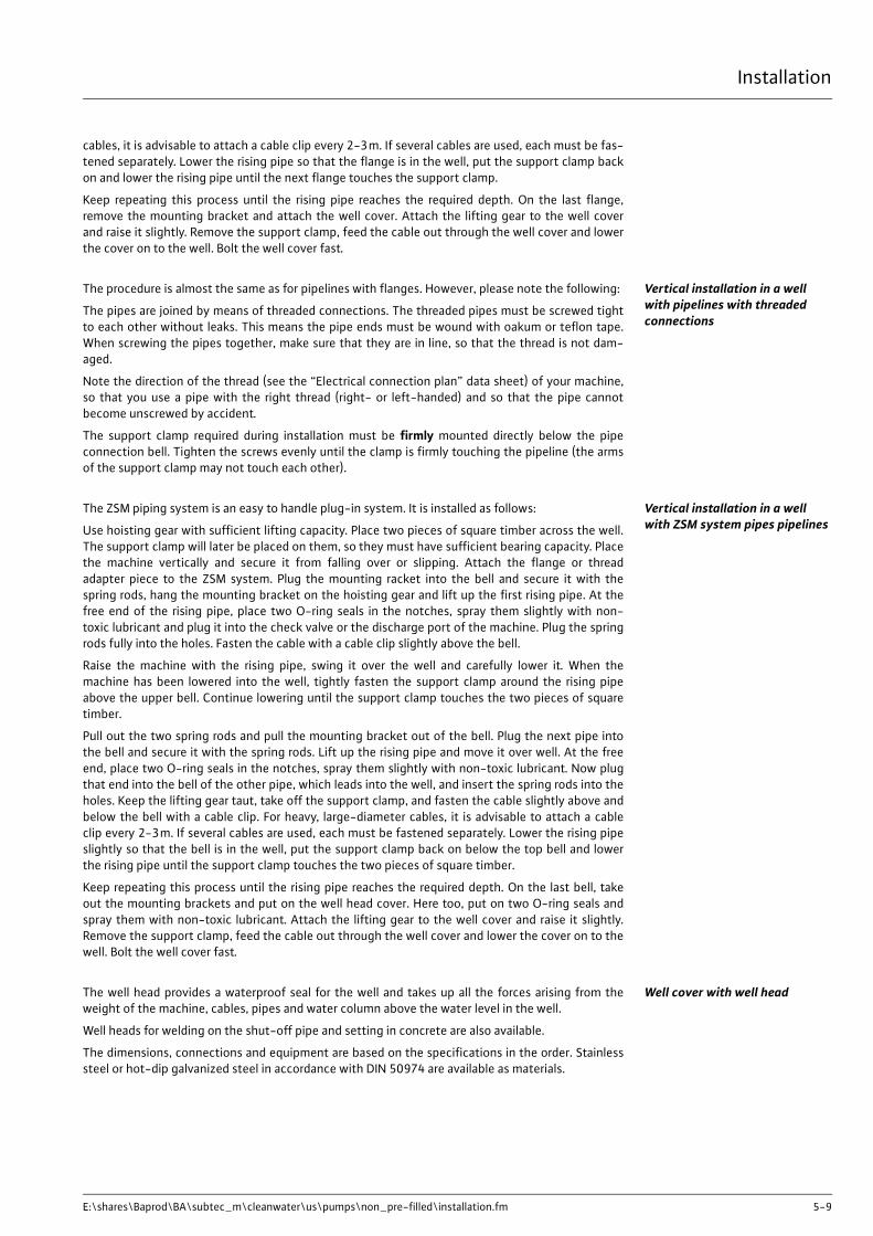
cables, it is advisable to attach a cable clip every 2-3m. If several cables are used, each must be fas-tened separately. Lower the rising pipe so that the flange is in the well, put the support clamp backon and lower the rising pipe until the next flange touches the support clamp.
Keep repeating this process until the rising pipe reaches the required depth. On the last flange,remove the mounting bracket and attach the well cover. Attach the lifting gear to the well coverand raise it slightly. Remove the support clamp, feed the cable out through the well cover and lowerthe cover on to the well. Bolt the well cover fast.
Vertical installation in a well with pipelines with threaded connections
The procedure is almost the same as for pipelines with flanges. However, please note the following:
The pipes are joined by means of threaded connections. The threaded pipes must be screwed tightto each other without leaks. This means the pipe ends must be wound with oakum or teflon tape.When screwing the pipes together, make sure that they are in line, so that the thread is not dam-aged.
Note the direction of the thread (see the “Electrical connection plan” data sheet) of your machine,so that you use a pipe with the right thread (right- or left-handed) and so that the pipe cannotbecome unscrewed by accident.
The support clamp required during installation must be firmly mounted directly below the pipeconnection bell. Tighten the screws evenly until the clamp is firmly touching the pipeline (the armsof the support clamp may not touch each other).
Vertical installation in a well with ZSM system pipes pipelines
The ZSM piping system is an easy to handle plug-in system. It is installed as follows:
Use hoisting gear with sufficient lifting capacity. Place two pieces of square timber across the well.The support clamp will later be placed on them, so they must have sufficient bearing capacity. Placethe machine vertically and secure it from falling over or slipping. Attach the flange or threadadapter piece to the ZSM system. Plug the mounting racket into the bell and secure it with thespring rods, hang the mounting bracket on the hoisting gear and lift up the first rising pipe. At thefree end of the rising pipe, place two O-ring seals in the notches, spray them slightly with non-toxic lubricant and plug it into the check valve or the discharge port of the machine. Plug the springrods fully into the holes. Fasten the cable with a cable clip slightly above the bell.
Raise the machine with the rising pipe, swing it over the well and carefully lower it. When themachine has been lowered into the well, tightly fasten the support clamp around the rising pipeabove the upper bell. Continue lowering until the support clamp touches the two pieces of squaretimber.
Pull out the two spring rods and pull the mounting bracket out of the bell. Plug the next pipe intothe bell and secure it with the spring rods. Lift up the rising pipe and move it over well. At the freeend, place two O-ring seals in the notches, spray them slightly with non-toxic lubricant. Now plugthat end into the bell of the other pipe, which leads into the well, and insert the spring rods into theholes. Keep the lifting gear taut, take off the support clamp, and fasten the cable slightly above andbelow the bell with a cable clip. For heavy, large-diameter cables, it is advisable to attach a cableclip every 2-3m. If several cables are used, each must be fastened separately. Lower the rising pipeslightly so that the bell is in the well, put the support clamp back on below the top bell and lowerthe rising pipe until the support clamp touches the two pieces of square timber.
Keep repeating this process until the rising pipe reaches the required depth. On the last bell, takeout the mounting brackets and put on the well head cover. Here too, put on two O-ring seals andspray them with non-toxic lubricant. Attach the lifting gear to the well cover and raise it slightly.Remove the support clamp, feed the cable out through the well cover and lower the cover on to thewell. Bolt the well cover fast.
Well cover with well headThe well head provides a waterproof seal for the well and takes up all the forces arising from theweight of the machine, cables, pipes and water column above the water level in the well.
Well heads for welding on the shut-off pipe and setting in concrete are also available.
The dimensions, connections and equipment are based on the specifications in the order. Stainlesssteel or hot-dip galvanized steel in accordance with DIN 50974 are available as materials.

Fig. 5-3: Well head
Horizontal or inclined installation (not top-heavy)
If installed in this manner, the machine is supported on two bearing blocks. The machine is installeddirectly in the pumped liquid and is flanged directly onto a pipeline. The bearing brackets must bemounted at the distances specified to prevent the machine distorting. The connected pipeline mustbe self-supporting, i.e. it may not be supported by the machine.

Installation
E:\shares\Baprod\BA\subtec_m\cleanwater\us\pumps\non_pre-filled\installation.fm 5-11
Fig. 5-4: Horizontal installation in a pumping station
Horizontal installation in a basin/tank
During assembly, make sure the pipes carry their own weight and thatthey and the foundations are strong enough.
The pipe system and the machine are fitted separately.
If installed horizontally, the machine is supported on two bearing brackets. The exact position canbe found on the planning documentation.
Drill fastening holes on the floor of your operating area at the point where the machine will be used.You will find specifications for the anchor bolts, distances between holes and their sizes in theassembly data sheets. Secure the bearing brackets on the base and using appropriate hoisting gear,bring the machine into the proper position and affix it with the required fastening material to thebearing brackets. Make certain that the screws and plugs are sufficiently stable.
Once the machine is firmly mounted, you can install the piping system or flange-connect a pipingsystem which is already in place. Make sure that the connections of the machine and the pipelineare level. Connect the discharge pipe to the discharge port.
A seal must be placed between the flanges of the pipeline and the unit. Tighten the fastening boltsin a cross pattern to avoid damaging the seal.
Please note that the connections on the machine may not support the pipe system, and that thepipe system must be mounted so that there is no vibration or tension (use elastic connectionpieces if necessary).
Lay the cables in such a manner that no-one (maintenance personnel etc.) will be endangered bythem at any time (operation, quick repairs). Do not damage the power supply lines. The electricalconnection must be carried out by an authorized technician in accordance with the “Electrical con-nection plan” data sheet.
Make sure that none of the power supply lines come near any otherproducts. This could damage the power supply lines and seriously dam-age the machine.
Also make sure the plugs and the type plate are facing upwards.
RemovalWhen removing the machine, make sure
- that it is first disconnected from the power supply by an authorized electrician and securedagainst inadvertent switching on,
- that the weight of the water column in the rising pipe has been taken into account whenlifting the machine, and
then you can remove the complete installation, for example by removing the pipe system from themachine, and the machine from the bearing blocks. To remove the machine, you must secure it andlift it out using lifting gear. You may have to dismantle part of the pipe system, as otherwise youcannot remove the machine.
Beware of poisonous substances!Machines which pump fluids hazardous to health present a fatalrisk. These machines must be decontaminated before any otherwork is carried out. Wear the necessary protective clothing/equipment when doing so.


Startup
E:\shares\Baprod\BA\subtec_m\cleanwater\us\pumps\startup.fm 6-1
6 StartupThe "Startup" chapter contains all the important instructions for the operating personnel for start-ing up and operating the machine safely.
The following specifications must be adhered to and checked:
- Type of installation
- Operating mode
- Minimum water coverage / max. submersion
- Motor full, or motor filling level correct
If the machine has not been operated for some time, check these speci-fications again and rectify any faults you find.
The operation and maintenance handbook must always be kept either bythe machine or in a place specially reserved for it where it is accessiblefor operating personnel at all times.
In order to prevent damage or serious injury during startup of the machine, the following pointsmust be observed:
The machine may only be started up by qualified personnel. The safetyadvice must be followed at all times.
- Every person working on the machine must have received, read and understood this operat-ing and maintenance manual. This must also be confirmed with a signature in the machineoperator list.
- Activate all safety devices and emergency stop elements before startup.
- Electrical and mechanical settings may only be made by specialists.
- This machine may only be used under the working conditions specified in this handbook.
Preparatory measuresThe machine has been designed and constructed using the very latest technology. Under normalworking conditions it will operate reliably and for long periods. The one condition for this is that allinstructions and advice are observed.
Please check the following:
- Cable guidance – no loops, slightly taut
- Check the temperature of the pumped liquid and the submersion depth – see technical data
- The machine is fixed securely – vibration-free operation must be assured
- The accessories – pedestal, bearing blocks etc. are securely fixed
- Our planning and assembly specifications are observed during installation
- The suction chamber of the pump sump and the pipelines must be completely free of dirt.Flush out the pipeline and the machine before connecting them to the supply network.
- An insulation test and filling level check of the engine filling must be carried out prior tostart-up. For details on this, see the "Maintenance" and "Installation" chapters.
- The sliders on the pressure side should be half opened during commissioning so that thepipeline can be bled.You can use an electrically actuated check valve to reduce or prevent water impact. Themachine can be switched on in a throttled or closed slider position (not "KP“ types).
However, do not operate the machine for long periods (>5min) with theslider closed or nearly closed, and do not run the machine dry.
The sliders on types "KP..." must always be completely opened. Neveroperate the machine if the sliders are closed.

Startup
6-2 WILO EMU 3.0
Electrical system Observe the relevant local and national regulations when laying out and selecting the electric linesas well as when connecting the motor. The motor must be protected by a motor protection switch.Have the motor connected in accordance with the "Electrical connection" data sheet. Pay attentionto the direction of rotation. If the direction of rotation is incorrect, the machine will not perform asspecified, and under certain circumstances, can become damaged. In accordance with the machinedata sheet, check the operating voltage and make certain that the current consumption remainsuniform during all phases.
Make sure that all temperature sensors and monitoring devices, such as the sealing chamber moni-tor, are connected and that their function is tested. For details on this, see the "Electrical connec-tion plan" data sheet.
Direction of rotation The machine must be connected in accordance with the data sheet “Electrical connection plan”.Rotation direction is controlled by a rotating field tester. This tester is switched on when the pumpis connected and displays the rotation direction of the rotating field. There must be a clockwiserotating field for the machine to run correctly.
If a counter-clockwise rotating field is displayed, two phases must be swapped.
The pump and performance data specified can only be achieved whenthere is a clockwise rotating field. The machine is not designed for oper-ation with a counter-clockwise rotating field.
Motor protection and activation types
Motor protection The minimum requirement is a thermal relay / motor protection switch with temperature compen-sation, differential triggering and an anti-reactivation device in accordance with VDE 0660 or theappropriate national regulations. If the machines are connected to electrical systems in which faultsfrequently occur, we recommend installing additional protective devices (overvoltage, undervolt-age or phase failure relays, lightning protection). Local and national regulations must be adhered towhen connecting the machine.
If the machine is used in a fire extinguishing or sprinkler system, thismay not be turned off by a safety device under any circumstances. Themotor protection may only signal faults.
Activation types for cables with free ends (without plugs)
Direct activation Motor protection should be set to the rated current when fully loaded. At partial load, we recom-mend that motor protection is set 5% above the measured current at the operating point.
Star-delta activation If the motor protection is installed in the line:Set the motor protection to 0.58 x the rated current. The maximum start-up time in star-deltamode is 3 seconds.
If the motor protection is not installed in the line:Set the motor protection to the rated current when fully loaded.
Starting transformer/soft start Motor protection should be set to the rated current when fully loaded. At partial load, we recom-mend that motor protection is set 5% above the measured current at the operating point. Themaximum start-up time at reduced voltage (approx. 70%) is 3 seconds.
Beware of electrical current!Electrical current can cause fatal injuries if not handled correctly!All machines with free cable ends (i.e. without plugs) must beconnected by a qualified electrician.

Startup
E:\shares\Baprod\BA\subtec_m\cleanwater\us\pumps\startup.fm 6-3
Operation with frequency transformers
The machine can be operated on frequency transformers.
Observe the data sheet in the appendix of this manual.
After startingThe rated current is briefly exceeded during the start-up procedure. Once this process has ended,the operating current should no longer exceed the rated current.
If the motor does not start immediately after the machine is switched on, it must be switched offimmediately. The start pauses specified in the technical data must be adhered to before starting upagain. If the fault recurs, the machine must be switched off again immediately. The machine mayonly be started again once the fault has been rectified.
The following items should be monitored:
- Operating voltage (permissible deviation +/- 5% of the rated voltage)
- Frequency (permissible deviation +/-2% of the rated frequency)
- Current consumption (permissible deviation between phases is a maximum of 5%)
- Voltage difference between the individual phases (max. 1%)
- Starts and stops per hour (see technical data)
- Air intake – observe minimum water coverage!
- Smooth running
Operation in the limit rangeThe maximum limit range deviation for operational data is +/-10% of the rated voltage and +3%to –5% of the rated frequency. Significant deviation from the operational data is to be expected(also see DIN VDE 0530, Section 1). The permissible voltage difference between the individualphases is a maximum of 1%. Continuous operation in the limit range is not recommended.


Maintenance
E:\shares\Baprod\BA\subtec_m\cleanwater\us\maintenance.fm 7-1
7 MaintenanceThe machine and the entire system must be inspected and maintained at regular intervals. The timelimit for maintenance is set by the manufacturer and applies to the general conditions of use. Themanufacturer should be consulted if the system is to be used with corrosive and/or abrasivepumped liquids, as the time limit between inspections may need to be reduced.
Note the following information:
- The operating and maintenance manual must be available to the maintenance personnel andits instructions followed. Only the repair and maintenance measures listed here may be per-formed.
- All maintenance, inspection and cleaning work on the machine and the system may only becarried out by trained specialists exercising extreme care in a safe workplace. Proper protec-tive clothing is to be worn. The machine must be disconnected from the electricity supplybefore any work is carried out. There must be no way that it can be inadvertently switched on.Additionally, the appropriate protective measures as defined by the BGV/GNV should beenforced when working in basins and/or containers.
- Above a weight of 50kg, only hoisting gear which has been officially approved and which is ina technically perfect condition should be used for lowering and raising the machine.
Make sure that all fastening devices, ropes and safety devices of thehand winch are in a technically perfect condition. Work may only com-mence if the auxiliary hoisting gear has been checked and found to be inperfect working order. If it is not inspected, danger to personnel mayresult.
- Electrical work on the machine and system must be carried out by an electrician. For machinesapproved for work in areas subject to explosion danger, please refer to the “Explosion protec-tion in accordance with the .... regulation” chapter. Defective fuses must be replaced. Underno circumstances are they to be repaired. Only fuses at the specified current and of the pre-scribed type may be used.
- When working with inflammable solvents and cleaning agents, fires, unshielded lighting andsmoking are prohibited.
- Machines which circulate fluids hazardous to health, or which come into contact with them,must be decontaminated. It must be ensured that no dangerous gases can form or arepresent.
If injuries involving hazardous pumping liquids or gases occur, first-aidmeasures must be performed in accordance with the notices in theworkplace and a doctor should be called immediately.
- Ensure that all necessary tools and materials are available. Tidiness and cleanliness guaranteesafe and problem-free operation of the machine. After working on the machine all cleaningmaterials and tools should be removed from it. All materials and tools should be stored in anappropriate place.
- Operating supplies such as oil and lubricants must be collected in appropriate vessels andproperly disposed of (in accordance with the 75/439/EEC directive and with §§5a, 5b AbfG).Appropriate protective clothing is to be worn for cleaning and maintenance jobs. This is to bedisposed of in accordance with waste code TA 524 02 and EC Directive 91/689/EEC. Onlylubricants expressly recommended by the manufacturer may be used. Oils and lubricantsshould not be mixed. Only use genuine parts made by the manufacturer.
A trial run or functional test of the machine must be performed asinstructed in the general operating conditions.
LubricantsThe motor is filled with a lubricant to lubricate the bearings and for additional internal cooling. Youcan either use drinking water (not distilled) or a special fluid supplied by the manufacturer (P35,P100) for this. Motors with a “T” in the motor code, e.g. NU 911T, are filled with drinking water.
Motors filled with drinking water may not be operated or stored wherethere is a risk of frost.

Maintenance
7-2 WILO EMU 3.0
Motors which are not marked with the “T” (with the exception of U15, U17, U21...) are filled withour manufacturer filling fluid. For details on this, please see the technical data.
The manufacturer fillings P35 and P100 are made from a propylene glycole concentrate (P35 =35%, P100 = 100%) and water (P35 = 65%). When topping up or filling the cooling system, thismanufacturer's filling should only be used in the stated ratio, otherwise frost and corrosion protec-tion cannot be guaranteed. The manufacturer's filling guarantees an anti-freeze effect to -15°C.
The manufacturer’s filling fluid must be disposed of properly, in accor-dance with official regulations. (If necessary, please contact the wasteassociation responsible!)Drinking water used for filling can be fed to the waste water.
Glycol Overview Technical data:
Maintenance intervals Overview of the maintenance intervals needed:
Status Production stopped Product used Possible alternatives
Product name Thermofrost Zitrec Pekasol L Propylene glycol
Company BPLEU Energie
GmbH & Co. KGProkühlsol
GmbHFauth & Co. KG
Basis Monopropylene glycol
Propane-1,2-diol
Propane-1,2-diol
Propane-1,2-diol
Color None None Light yellow None
Purity 80% - 94.99% 96% - 98%
Density 1.056 g/ml 1.051 g/ml 1.050 g/cm3 1.051 g/ml
Boiling point 140 °C 164 °C 185 °C 188 °C
pH value 7.9 9.9 7.5 - 9.5 -
Water 3% - 9.99% Max. 5%. - 0,20%
Nitrite None None None None
Amine - None None None
Phosphate - None None None
Silicate - None None None
Water hazard class 1 1 1 1
FDA approval - Yes - -
HT1 approval - Yes - -
Afssa approval - Yes - -
Remarks - - - For medical use
Table 7-1: Technical Data – Glycol Overview

Maintenance
E:\shares\Baprod\BA\subtec_m\cleanwater\us\maintenance.fm 7-3
Monthly- Monitoring the current consumption and voltage
- Checking the used relays for posistors, sealing room monitor, etc.
Every six months- Checking the insulation resistance
- Visual inspection of the power supply cable
- Visual inspection of accessories, e.g. pressure shroud, etc.
Yearly- Functional inspection of all safety and monitoring devices and auxiliary hoisting gear
Maintenance tasksOverview of the individual maintenance intervals:
Monitoring the current con-sumption and voltage
The current consumption and voltage is to be monitored periodically during all 3 phases. Thisremains constant during normal operation. Slight fluctuations are a result of the composition of thepumped fluid. The current consumption can assist in early detection and correction of damage and/or faulty operation in the impeller/propeller, bearings and/or the motor. More extensive resultingdamage can thus be largely prevented and the risk of a total failure can be reduced.
Checking the used relays for posistors, sealing room moni-tor, etc.
Check the relays used are functioning fault-free. Defective devices must be immediately replaced,because these cannot ensure safe operation of the machine. The test procedure details should befollowed closely (in the operating instructions for each relay).
Checking the insulation resis-tance
To check the insulation resistance, the power supply cable must be disconnected. The resistancecan then be measured with an insulation tester (measuring voltage = 1000V DC). The following val-ues may not be exceeded:
The insulation resistance may not be below 20mega-ohms during initial operation. For all furthermeasurements the value must be greater than 2mega-ohms.
Insulation resistance too low: Moisture may have penetrated the cable and/or the motor.
Do not connect the machine, consult manufacturer.
Visual inspection of the power supply cable
The power supply line must be examined for bubbles, cracks, scratches, chafed areas and/orcrushed sections. If damage is found, the power cable must be exchanged immediately.
The cables may only be changed by the manufacturer or an authorized/certified service workshop. The machine may not be used again until thedamage has been adequately rectified.
Visual inspection of accesso-ries
Inspect accessories such as the pressure shroud, etc., to check whether they are secured in a stablemanner and are leakproof. Loose and/or defective accessories should be repaired immediately orreplaced.
Functional inspection of safe-ty and control devices
Monitoring devices are temperature sensors in the motor, sealing room monitors, motor protectionrelays, overvoltage relays, etc.
Motor protection and overvoltage relays and other trip elements can generally be triggered manu-ally for test purposes.
To inspect the temperature sensor, the machine must be cooled to ambient temperature and theelectrical supply cable of the monitoring device in the switch cabinet must be disconnected. Themonitoring device is then tested with an ohmmeter. The following values should be measured:
Bi-metal sensor: Value = “0” - throughput
PTC sensor: A PTC sensor has a cold resistance of between 20 and 100ohms. For 3 sensors in seriesthis would result in a value of between 60 and 300ohms.
PT 100 sensor: PT 100 sensors have a value of 100ohms at 0°C. Between 0°C and 100°C this valueincreases by 0.385ohms per 1°C. PT 20 sensors have a value of 107.7ohms at 20°C.
In the case of larger deviations, please consult the manufacturer.

Maintenance
7-4 WILO EMU 3.0
Please consult the appropriate operating manual for details on inspecting the safety and monitor-ing devices on the auxiliary lifting gear.

Shutdown
E:\shares\Baprod\BA\subtec_m\general\us\shutdown.fm 8-1
8 ShutdownThis chapter provides an overview of the various ways to shut down the machine.
Temporary shutdownFor this type of shutdown, the machine remains installed and is not cut off from the electricity sup-ply. For temporary shutdown, the machine must remain completely submerged so that it is pro-tected from frost and ice. Make sure the operating room and the pumped fluid cannot be coveredby ice.
This ensures that the machine is always ready for operation. During longer shutdown periods, carryout a regular (monthly to quarterly) function run for a period of 5 minutes.
Final shutdown / storageSwitch off the system, disconnect the machine from the electricity supply and dismantle and storeit. Note the following information concerning storage:
- Clean the machine.
- Store it in a clean, dry place, protect the machine against frost.
- Place it down vertically onto a firm foundation and secure it against falling.
- Seal the intake and discharge ports of pumps with suitable material (such as foil).
- Support the electric connecting lead on the cable lead-in to help avoid a permanent deforma-tion.
- Protect the ends of the electric power cable from moisture.
- Protect the machine from direct sunshine as a preventive measure against brittleness in elas-tomer parts and the propeller and casing coating.
- When storing the machine in a garage please remember: Radiation and gases which occurduring electric welding destroy the elastomers of the seals.
- During lengthy periods of storage, regularly (for example every six months) turn the impelleror propeller by hand. This prevents indentations in the bearings and stops the rotor from rust-ing up.
- See also “Transport and Storage”.
Restarting after an ex-tended period of storage
Before restarting the machine, clean it of dust and oil deposits. Then carry out the necessary main-tenance actions (see “Maintenance”). Check that the mechanical shaft seal is in good order andworking properly.
Caution
Only carry out a function run under the proper conditions of oper-ation and use (see “Product Description”). Never run the machinedry. This can result in irreparable damage!
Beware of hot parts!When removing the machine, be careful of the temperature of thehousing components. These can heat up to well above 40°C. Let themachine cool down to ambient temperature before you touch it.
CautionFor machines filled with drinking water, drain out the water andlet the machine dry out if it is not operated for more than4 weeks, or if there is a risk of freezing.

Shutdown
8-2 WILO EMU 3.0
Once this work has been completed, the machine can be installed (see “Installation”) and connected to the electricity supply by a specialist. See “Startup” a for instructions on restarting.
Only restart the machine if it is in perfect condition and ready for opera-tion.
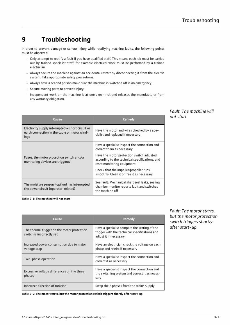
Troubleshooting
E:\shares\Baprod\BA\subtec_m\general\us\troubleshooting.fm 9-1
9 TroubleshootingIn order to prevent damage or serious injury while rectifying machine faults, the following pointsmust be observed:
- Only attempt to rectify a fault if you have qualified staff. This means each job must be carriedout by trained specialist staff, for example electrical work must be performed by a trainedelectrician.
- Always secure the machine against an accidental restart by disconnecting it from the electricsystem. Take appropriate safety precautions.
- Always have a second person make sure the machine is switched off in an emergency.
- Secure moving parts to prevent injury.
- Independent work on the machine is at one's own risk and releases the manufacturer fromany warranty obligation.
Fault: The machine will not start
Fault: The motor starts, but the motor protection switch triggers shortly after start-up
Cause Remedy
Electricity supply interrupted – short circuit or earth connection in the cable or motor wind-ings
Have the motor and wires checked by a spe-cialist and replaced if necessary
Fuses, the motor protection switch and/or monitoring devices are triggered
Have a specialist inspect the connection and correct them as necessary
Have the motor protection switch adjusted according to the technical specifications, and reset monitoring equipment
Check that the impeller/propeller runs smoothly. Clean it or free it as necessary
The moisture sensors (option) has interrupted the power circuit (operator-related)
See fault: Mechanical shaft seal leaks, sealing chamber monitor reports fault and switches the machine off
Table 9-1: The machine will not start
Cause Remedy
The thermal trigger on the motor protection switch is incorrectly set
Have a specialist compare the setting of the trigger with the technical specifications and adjust it if necessary
Increased power consumption due to major voltage drop
Have an electrician check the voltage on each phase and rewire if necessary
Two-phase operation Have a specialist inspect the connection and correct it as necessary
Excessive voltage differences on the three phases
Have a specialist inspect the connection and the switching system and correct it as neces-sary
Incorrect direction of rotation Swap the 2 phases from the mains supply
Table 9-2: The motor starts, but the motor protection switch triggers shortly after start-up

Troubleshooting
9-2 WILO EMU 3.0
Fault: Machine runs but does not pump
Fault: The machine runs, but not at the stated op-erating levels
Impeller/propeller impeded by adhesive mate-rial, blockages and/or solid matter, increased current consumption
Switch off the machine, secure it against being switched on again and free the impeller/propeller or clean the suction port
The pumped fluid is too dense Contact the manufacturer
Cause Remedy
Table 9-2: The motor starts, but the motor protection switch triggers shortly after start-up
Cause Remedy
No pumped fluid Open the container intake or sliders
Intake blockedClean the intake, slider, suction port or intake strainer
Impeller/propeller blocked or obstructedSwitch off the machine, secure it against being switched on again and free the impeller/propeller
Defective hose or piping Replace defective parts
Intermittent operation Check the control panel
Table 9-3: Machine runs but does not pump
Cause Remedy
Intake blockedClean the intake, slider, suction port or intake strainer
Slide in the discharge line closed Fully open the slide
Impeller/propeller blocked or obstructedSwitch off the machine, secure it against being switched on again and free the impeller/propeller
Incorrect direction of rotation Replace 2 phases on the mains supply
Air in the system Check the pipes, pressure shroud and/or pump unit, and bleed if necessary
Machine pumping against excessive pressureCheck the slide in the discharge line, if neces-sary open it completely, use a different impel-ler or contact the factory
Signs of wear Replace worn parts
Defective hose or piping Replace defective parts
Inadmissible levels of gas in the pumped liquid Contact the factory
Two-phase operation Have a specialist inspect the connection and correct it as necessary
Table 9-4: The machine runs, but not at the stated operating levels

Troubleshooting
E:\shares\Baprod\BA\subtec_m\general\us\troubleshooting.fm 9-3
Fault: The machine does not run smoothly and is noisy
Fault: Mechanical shaft seal leaks, sealing cham-ber monitor reports fault and switches the ma-chine off
(Sealing chamber monitoring is optional, and is not available for all types. For details on this, see theorder confirmation or the electrical terminal connection plan.)
Excessive decrease in the water table during operation
Check the supply and capacity of the system, and inspect the level control settings and function
Cause Remedy
Table 9-4: The machine runs, but not at the stated operating levels
Cause Remedy
Machine is running in an impermissable oper-ation range
Check the operational data of the machine and correct if necessary and/or adjust the operating conditions
The suction port, strainer and/or impeller/pro-peller is blocked
Clean the suction port, strainer and/or impel-ler/propeller
The impeller is impededSwitch off the machine, secure it against being switched on again and free the impeller
Inadmissible levels of gas in the pumped liquid Contact the factory
Two-phase operation Have a specialist inspect the connection and correct it as necessary
Incorrect direction of rotation Replace 2 phases on the mains supply
Signs of wear Replace worn parts
Defective motor bearing Contact the factory
The machine is installed with mechanical strain
Check the installation, use rubber spacers if necessary
Table 9-5: The machine does not run smoothly and is noisy
Cause Remedy
Condensation build-up due to lengthy stor-age and/or temperature fluctuation
Operate the machine briefly (max. 5min.) without sealing chamber monitoring
Expansion tank (optional for polder pumps) is too high
Install the expansion tank no more than 10m above the top edge of the suction port
Increased leakage when running in new mechanical shaft seals
Change the oil
Defective sealing chamber cables Replace the moisture sensors
Mechanical shaft seal is defectiveReplace the mechanical shaft seal after con-tacting the factory
Table 9-6: Mechanical shaft seal leaks, sealing chamber monitor reports fault and switches the machine off

Further steps for trouble-shooting
If the items listed here do not help you rectify the fault, contact our customer service. They canhelp you as follows:
- Telephone or written help from customer service
- On-site support from customer service
- Checking and repairing the machine at the factory
Note that you may be charged for some services provided by our customer support.Customer service will provide you with details on this.

List of machine operators and maintenance
E:\shares\Baprod\BA\subtec_m\general\us\annex_a.fm A-1
A List of machine operators and mainte-nance
List of machine operatorsAll persons working on or with the product confirms with their signatures that they have received,read and understood this operating and maintenance manual. In addition, they obligate themselvesto conscientiously follow the instructions provided. Non-observation releases the manufacturerfrom any warranty obligations.
Name Starting date Signature
Table A-1: List of machine operators

List of machine operators and maintenance
A-2 WILO EMU 3.0
Maintenance and inspec-tion log
Every person is required to enter all maintenance and alteration work which then is to be confirmedwith the person's own signature and that of their supervisor.
This list is to be shown on request to representatives of controlling organizations, governmentinspection teams and the manufacturer!
Maintenance / Revision on Date Signature Signature of the
person in charge
Table A-2: Maintenance and inspection log

Operation with a static frequency converter
E:\shares\Baprod\BA\subtec_m\appendix\us\general\fc.fm B-1
B Operation with a static frequency converter
WILO products can be operated with standard frequency converters. These are normally pulse-width-modulated converters. However, the following points must be observed when operating theconverter:
Selecting the motor and converter
Any standard WILO motor can be used. If the rated voltage is above 415 V, you must consult themanufacturer. Because of the additional heating caused by harmonics, the rated power of themotor should be around 10% more than the power requirement of the pump. For converters with alow-harmonic output, it may be possible to reduce the 10% power reserve. This is normally doneby using output filters. Ask the converter manufacturer.
The size of the converter depends on the rated motor current. Selecting the motor power in kW cancause problems, since submersible motors have different specifications to standard motors. Wastewater motors are marked with the appropriate rated power (type sheet power in catalog).
Minimum speed for submersible pumps (well pumps)
Submersible pumps have water-lubricated bearings. A minimum speed is required in order for alubricating film to form.
Continuous operation at frequencies below 25 Hz (30 Hz 4-pole) must be avoided, since the lackof lubrication and possible occurrence of mechanical vibrations may cause damage to the bearings.
The lowest speed range (up to 12.5 Hz) should be passed though within2 seconds.
In practice, the speed should only be lowered to the extent that a pump flow of at least 10% of themaximum flow remains. The precise value depends on the type – ask the manufacturer for details.
Minimum speed for waste water and sewage pumps
There is no prescribed minimum speed for waste water and sewage pumps.
However, make sure that the motor operates without jerking or vibrating, especially in the lowerspeed range. Otherwise, the mechanical shaft seals could be damaged and start leaking.
OperationIt is important that the pump motor operates across the entire control range without vibrations,resonance, oscillation or excessive noise (ask the manufacturer if necessary).
Increased motor noise caused by the harmonics of the power supply is normal.
When configuring the converter, always make sure the quadratic curve (U/F characteristic) forpumps and fans is correctly set. This ensures that the output voltage at < 50 Hz frequencies isadjusted to the power requirement of the pump. Newer converters feature an automatic poweroptimization function which achieves the same effect. See the converter operating manual for thissetting and other parameters.
Max. voltage peaks and rise speed
Submersible motors with water-cooled windings are more susceptible to voltage peaks than drymotors.
The following thresholds may not be exceeded:Max. voltage rise speed: 500 V/µsMax. voltage peak to earth: 1250 V
These values apply for well pumps < 1 kV and can usually be attained by replacing a sinusoidal filteror dV/dt filter. For motors > 1 kV, the permissible values can be obtained from the plant. It remainsthe case that the lowest possible pulse frequency should be set.

Operation with a static frequency converter
B-2 WILO EMU 3.0
EMC In order to comply with EMC (electromagnetic compatibility) regulations, it may be necessary to useshielded wires, lay cables in metal tubes and install filters. The exact actions required to complywith the EMC directives depend on the converter type, converter manufacturer, length of cable laidand other factors. In individual cases it is therefore necessary to look up the actions to be taken inthe converter operating manual or contact the manufacturer directly.
Motor protection As well as the built-in electrical current monitor system in the converter, or the thermal relay in theswitching system, we recommend installing temperature sensors in the motor. Cold conductortemperature sensors (PTC) and resistor temperature sensors (PT 100) are both suitable.
Explosion-proof motors (whose type code has the addition “Ex”) mustalways be fitted with cold-type thermistors in frequency conversionmode. Also, an approved motor protection relay for cold-type ther-mistors (such as MSS) must be used.
Operation up to 60 Hz A WILO submersible motor can be adjusted up to 60 Hz provided the motor has been rated for thepump’s higher power requirement. However, the rated power should be taken from the 50 Hz datasheets.
Efficiency As well as the efficiency of the motor and the pump, the efficiency of the converter (approx. 95 %)must also be taken into account. The efficiency of all components is lower when the speed isreduced.
Formulas
Summary As long as all these points are taken into account and the instructions for the converter are fol-lowed, speed-regulated operation with WILO products is possible without any problems.
Pump flow Pump head Power
Table B-1: Formulas
Q2 = Q1 * n2n1 H2 = H1 * n2
n1
2P2 = P1 * n2
n1
3

Anti-vortex plate
E:\shares\Baprod\BA\subtec_m\appendix\us\clean_water\anti_vortex_plate.fm C-1
C Anti-vortex plate
General product infor-mation
The anti-vortex plate can be used for horizontally installed machines. It is fitted above the suctionstrainer. It is fastened to the motor and pump housing by means of two metal brackets. The anti-vortex plate prevents air from being sucked in. This means the machine runs smoothly and quietly.
The anti-vortex plate is normally supplied already fitted. It needs to bedisassembles or fitted when the filling level of the fluid in the motor hasto be checked or topped up.
Installation
Assembly- Place the anti-vortex plate on the machine. The fixed bracket of the anti-vortex plate mustlie on the motor and pump housing. The anti-vortex plate must completely cover the suctionstrainer.
- Press the loose bracket on to the fixed bracket from below.
- Fasten both brackets, each with two hex bolts and nuts.
Dismantling- Remove the four hex bolts and nuts from the two brackets.
- Remove the loose bracket.
- Now you can remove the anti-vortex plate.
Fig. C-1: Assembling / dismantling the anti-vortex plate
Motor housing Bracket - looseAnti-vortex plate Bracket - fixed to
the anti-vortex plate
Pump housing


Instructions on filling the NU 611 and NU 811 motors
E:\shares\Baprod\BA\subtec_m\appendix\us\clean_water\odesse_motor.fm D-1
D Instructions on filling the NU 611 and NU 811 motors
General product information
The procedures for filling, draining and checking fluid levels for these motors differ from our othermotors. The steps for this procedure are described in this chapter.
Only motors that are completely and correctly filled guarantee problem-free operation.
Special characteristicsThe motor is filled with the manufacturer's special fluid. These motors can be stored at tempera-tures down to -40 °C for one year and can be operated at down to -8 °C. These motors are alreadyfilled by the manufacturer and are ready for operation.
Motors with a “T” in the motor code are filled with drinking water (notdistilled). This work must be performed on site and before commission-ing. Motors filled with drinking water are susceptible to frost.
Motor filling fluid
Checking and correcting the filling level
1 Clean the motor and place it upright so that the shaft (1) is at the top.
The motor must be secured against falling over.
2 Undo the screw (2) located on the side or on the top of the motor housing.
3 The fluid in the motor must reach to the top of the opening.
4 Top up the fluid in the motor if necessary. Fill the motor with the manufacturer's fluid or withdrinking water (not distilled water) through the hole in the screw (2). Fill up the motor untilwater comes out of the hole.
If the motor is filled with the manufacturer's fluid, do not top up withmore than 1/2 liter of drinking water (not distilled water). If the motor isfilled with more than 1/2 liter of drinking water (not distilled water), theantifreeze effect is impaired.
5 After testing, screw in the screw (2) again.
Filling the motor1 Clean the motor and place it upright so that the shaft (1) is at the top.
The motor must be secured against falling over.
2 Undo the screw (2) located on the side or on the top of the motor housing.
3 Fill the motor with water through the hole in the screw (2).
The motor can be filled with the manufacturer's fluid or with drinkingwater (not distilled water). If the motor is filled with drinking water (notdistilled water), there is no antifreeze effect.
4 Fill up the motor until water comes out of the hole.
5 Leave the motor open for 30 minutes to allow any residual air to escape.
6 Check the fluid level and top up to the upper edge of the hole if necessary.

Instructions on filling the NU 611 and NU 811 motors
D-2 WILO EMU 3.0
Fig. D-1: Filling the motor
Draining the motor 1 Lay the motor horizontally and remove the screw (1).
2 The motor fluid flows out.
3 Slightly raise the motor to allow the remaining fluid to drain out.
Fig. D-2: Draining the motor
Screw (2)
Shaft (1)
Screw (1)

Use as a sprinkle pump
E:\shares\Baprod\BA\subtec_m\appendix\us\clean_water\sprinkler.fm E-1
E Use as a sprinkle pump
Proper use and fields of application
These machines are used in sprinkler fire extinguishing systems in buildings. The units are designedfor this use and have been tested and certified by a named authority.
Only machines which are suitably certified (VdS, PAWUS etc.) may beused as sprinkler pumps. You can find the certification on the order con-firmation or the machine data sheet.
Approved unitsThe table shows a list of certified units. The certification is only valid when the motor and pump areused as a unit. The certification becomes invalid if they are used as individual components.
Features of sprinkler pumps
Sprinkler pumps are clean water units with a prefilled motor. They can also be used with pressureshrouds.
Only clean water which does cause sediment may be used as the pumped fluid. The temperature ofthe pumped fluid may not exceed 25 °C.
The guaranteed emergency flow volume is at least 2 %Qz on normal units and at least 4 %Qz onunits with pressure shrouds. The maximum period pumping the emergency flow volume is 48 hours.
The operating company is responsible for ensuring that the required vol-ume of pumped fluid and a sufficient power supply are available. Fur-thermore, sprinkler pumps may not be deactivated when in use bymonitoring devices such as surge voltage protectors and FI protectionswitches.
Technical dataYou can find the technical data of the machine on the data sheet in this manual, the product datasheet in our catalog or in the specifications on the order confirmation.
The minimum water coverage level refers to the top edge of the discharge port of an uprightmachine.
On horizontally installed machines, it refers to the top edge of the intake strainer.
When planning, you should add a safety allowance of 0.5 m to the statednet positive suction head.
Signs usedThe following signs are attached to the machine.
Pump type Motor type VDS approval
K 86… NU 60-2… / NU 80-2… P 4840420
K 87… NU 60-2… / NU 80-2… P 4840421
KM 350… NU 80-2… / NU901-2… P 4840422
KM 750… NU 80-2… / NU901-2… P 4840423
KM 1300… NU 80-2… / NU901-2… P 4840424
Table E-1: Overview of approved sprinkler pumps

Use as a sprinkle pump
E-2 WILO EMU 3.0
Type plate The type plate is attached to the motor casing. This sign contains the technical data.
Fig. E-1: Type plate
P-Typ M-Typ
S/N MFY
U QZ S
I HZ OTS/E
IST Cos TPF max
P SF
F ISF IP
N MC
IMø Mat.Ph VdS

Data Sheet - Electrical Connection
E:\shares\Baprod\BA\subtec_m\e_plan\us\electric.fm F-1
F Data Sheet - Electrical Connection
Safety notesThe motor must be connected only by an authorized electrician: The relevant local regulations mustbe observed when laying the cables and connecting the motor. The installation of motor protectionequipment is mandatory. Refer to the Machine Data Sheet for the electrical values. The motor turnsin the correct direction with a clockwise rotary field.
Insulation resistanceThe insulation resistance must not fall below 20 MOhm on commissioning. The insulation resis-tance must be >= 2 MOhm for further tests. The direct measuring voltage is 1000 V.
Monitoring equipment
Monitoring deviceWire
identification
Recommended analyzing
deviceThreshold Triggered
condition
Motor monitoring
Bimetal sensor(1st temperature circuit)
20/21 - - Switch off
Bimetal sensor(2nd temperature circuit)
20/21/22 - -
Low temperature: early warningHigh temperature: switch off
PTC sensor(1st temperature circuit)
10/11 CM-MSS Preset Switch off
PTC sensor(2nd temperature circuit)
10/11/12 CM-MSS Preset
Low temperature: early warningHigh temperature: switch off
PT-100 winding temperature sensor
1/2 DGW 2.01G Depending on winding*
Switch off
PT-100 bearing temperature sensor T1/T2 DGW 2.01G 100°C Switch off
Pressure switch D20/D21 - - Switch off
Thermo float switch 20/21 - - Switch off
Leak monitoring
Seal chamber / motor chamber / terminal chamber monitoring
DK/DK NIV 101 30 KOhmWarning or switch off
Seal chamber monitoring for Ex
DK/DK ER 143 30 KOhm Switch off
Table F-1: * Limit temperature: insulation class F = 140°, insulation class H = 160°, for oil motors = 110°, PVC wire = 80°, PE2 wire = 90°

Data Sheet - Electrical Connection
F-2 WILO EMU 3.0
When used in Ex-protected areas
The temperature monitoring system should be connected in such a manner that if the early warningis triggered an automatic switch on can be performed. If a switch off is triggered then switching onagain should only be possible if the release button has been manually activated!
Wire designation of the connection lead
1 designation
2 core
3 main cable
4 control cable
5 electrode cable
6 green-yellow
7 blue
8 black
9 brown
10 protective conductor
11 motor connection cable
12 motor connection cable beginning
13 motor connection cable end
14 motor connection cable low speed
15 motor connection cable high speed
16 cold type thermistor as per DIN 44081
17 cold type thermistor beginning
18 cold type thermistor high temperature per DIN 44081
19 cold type thermistor low temperature as per DIN 44081
20 bimetallic thermistor (break contact) 250V 2A cos j = 1
21 bimetallic thermistor beginning
22 bimetallic thermistor high temperature (break contact)
23 bimetallic thermistor low temperature (break contact)
24 temperature control Pt 100 beginning as per DIN 43760 B
Leak chamber monitoring K20/21
Coupling relay (CM-MSS or NIV 101)
-Warning or switch off
Protection device provided by customer
Bimetal relay / motor protection switch - -
Rated motor current Switch off
Dry-run protection with float
- - - Switch off
Dry-run protection with electrode
- NIV 105 30 KOhm Switch off
Monitoring deviceWire
identification
Recommended analyzing
deviceThreshold Triggered
condition
Table F-1: * Limit temperature: insulation class F = 140°, insulation class H = 160°, for oil motors = 110°, PVC wire = 80°, PE2 wire = 90°
Data Sheet - Electrical Connection
E:\shares\Baprod\BA\subtec_m\e_plan\us\electric.fm F-3
25 temperature control Pt 100 end as per DIN 43760 B
26 leakage float (break contact) 250V 3A cos j = 1
27 motor overpressure switch (break contact) 250V 4A cos j = 1
28 thermal float (break contact) 250V 2A cos j = 1
29 sealing chamber control
30 bearing temperature control
31 bearing temperature control Pt 100 as per DIN 43760 B
32 motor - terminal and sealing chamber control
33 motor and terminal chamber control
34 thermal float and bimetallic thermistor (break contact) 250V 2A cos j = 1
35 Thermal float and cold type thermistors as per DIN 44081
36 Screening
37 Cold type thermistors end as per DIN 44081
38 Cold type thermistors tapping as per DIN 44081
39 white
40 Motor overpressure switch and cold type thermistors as per DIN 44081
41 Thermal float and motor over pressure switch (break contact) 250V 2A cos j = 1
42 Bi-metallic thermistors and motor overpressure switch (break contact) 250V 2A cos j = 1
43 red
44 motor chamber monitor
45 motor leak and sealing chamber monitor
46 motor and sealing chamber monitor
47 yellow
48 orange
49 green
50 white-black
51 Leak monitoring
52 Bimetal & Pt 100 temperature sensor start
53 Gray
54 Gray / (blue)
55 Cold conductor temperature sensor for winding/oil as DIN 44081

DATENBLATT - ELEKTRISCHER ANSCHLUSS
Sicherheitshinweise:Der Anschluß des Motors darf nur von einer autorisierten Elektrofachkraft vorgenommen werden. Es sind bei der Leitungsverlegung und beim Anschließen des Motors die VDE- und die örtlichen Vorschriften zu beachten. Der Einbau eines Motorschutzes ist zwingend vorgeschrieben. Die elektrischen Werte sind aus dem Maschinendatenblatt zu entnehmen. Bei rechtsdrehendem Drehfeld hat der Motor die richtige Drehrichtung.
Isolationswiderstand:Bei Erstinbetriebnahme darf der Isolationswiderstand 20 MΩ nicht unterschreiten. Bei weiteren Prüfungen muß der Isolationswiderstand ≥2 MΩ sein. Die Meßgleichspannung ist 1000 V
Aderbezeichnung der Anschlußleitung:
Bezeichnung 1) Ader 2)
Hauptleitung 3)
PE grün-gelb 6) Schutzleiter 10)
U 3V 4 Motoranschlußleitung 11)
W 520 121 2
Bi-Metalltemperaturfühler (Öffner) 250V 2A cos ϕ =1 20)
WILOEMU GmbH 10311111.DOC

G EC declaration of conformity


WILO SENortkirchenstraße 10044263 DortmundGermanyT +49 231 4102-0F +49 231 [email protected]
AlgeriaBad Ezzouar, Dar El BeidaT +213 21 [email protected]
Armenia375001 YerevanT +374 10 [email protected]
Bosnia and Herzegovina71000 SarajevoT +387 33 [email protected]
Georgia0179 TbilisiT +995 32 [email protected]
Macedonia1000 SkopjeT +389 2 [email protected]
Mexico07300 MexicoT +52 55 [email protected]
Moldova2012 ChisinauT +373 2 [email protected]
Rep. MongoliaUlaanbaatarT +976 11 [email protected]
Tajikistan734025 DushanbeT +992 37 [email protected]
Turkmenistan744000 AshgabadT +993 12 [email protected]
Uzbekistan100015 TashkentT +998 71 [email protected]
March 2009
Wilo – International (Subsidiaries)
Wilo – International (Representation
ArgentinaWILO SALMSONArgentina S.A.C1295ABI CiudadAutónoma de Buenos AiresT +54 11 4361 [email protected]
AustriaWILO PumpenÖsterreich GmbH1230 WienT +43 507 507-0
AzerbaijanWILO Caspian LLC1065 BakuT +994 12 [email protected]
BelarusWILO Bel OOO220035 MinskT +375 17 [email protected]
BelgiumWILO SA/NV1083 GanshorenT +32 2 [email protected]
BulgariaWILO Bulgaria Ltd.1125T +359 2 [email protected]
CanadaWILO Canada Inc.Calgary, Alberta T2A 5L4T +1 403 [email protected]
ChinaWILO China Ltd.101300 BeijingT +86 10 [email protected]
CroatiaWILO Hrvatska d.o.o.10090 ZagrebT +38 51 [email protected]
Czech RepublicWILO Praha s.r.o.25101 CestliceT +420 234 [email protected]
DenmarkWILO Danmark A/S2690 KarlslundeT +45 70 [email protected]
EstoniaWILO Eesti OÜ12618 TallinnT +372 [email protected]
FinlandWILO Finland OY02330 EspooT +358 207401540
FrancePompes Salmson78403 ChatouT +33 820 0000 [email protected]
Great BritainWILO (U.K.) Ltd.DE14 2WJ Burton-Upon-TrentT +44 1283 [email protected]
GreeceWILO Hellas AG14569 Anixi (Attika)T +302 10 [email protected]
HungaryWILO Magyarország Kft2045 Törökbálint(Budapest)T +36 23 [email protected]
IrelandWILO Engineering Ltd.LimerickT +353 61 [email protected]
ItalyWILO Italia s.r.l.20068 PeschieraBorromeo (Milano)T +39 [email protected]
KazakhstanWILO Central Asia050002 AlmatyT +7 727 [email protected]
KoreaWILO Pumps Ltd.621-807 GimhaeGyeongnamT +82 55 [email protected]
LatviaWILO Baltic SIA1019 RigaT +371 67 [email protected]
LebanonWILO SALMSONLebanon12022030 El MetnT +961 4 [email protected]
LithuaniaWILO Lietuva UAB03202 VilniusT +370 5 [email protected]
The NetherlandsWILO Nederland b.v.1551 NA WestzaanT +31 88 9456 [email protected]
NorwayWILO Norge AS0975 OsloT +47 22 [email protected]
PolandWILO Polska Sp. z.o.o.05-090 RaszynT +48 22 [email protected]
PortugalBombas Wilo-SalmsonPortugal Lda.4050-040 PortoT +351 22 [email protected]
RomaniaWILO Romania s.r.l.077040 Com. ChiajnaJud. IlfovT +40 21 [email protected]
RussiaWILO Rus ooo123592 MoscowT +7 495 [email protected]
Saudi ArabiaWILO ME - RiyadhRiyadh 11465T +966 1 [email protected]
Serbia and MontenegroWILO Beograd d.o.o.11000 BeogradT +381 11 2851278
u
SlovakiaWILO Slovakia s.r.o.82008 Bratislava 28T +421 2 [email protected]
SloveniaWILO Adriatic d.o.o.1000 LjubljanaT +386 1 [email protected]
South AfricaSalmson South Africa1610 EdenvaleT +27 11 [email protected]
SpainWILO Ibérica S.A.28806 Alcalá de Henares(Madrid)T +34 91 [email protected]
SwedenWILO Sverige AB35246 VäxjöT +46 470 [email protected]
SwitzerlandEMB Pumpen AG4310 RheinfeldenT +41 61 [email protected]
TaiwanWILO-EMU Taiwan Co. Ltd.110 TaipehT +886 227 [email protected]
TurkeyWILO Pompa SistemleriSan. ve Tic. A.S.34530 IstanbulT +90 216 [email protected]
UkrainaWILO Ukraina t.o.w.01033 KiewT +38 044 [email protected]
VietnamPompes Salmson VietnamHo Chi Minh-Ville VietnamT +84 8 [email protected]
United Arab EmiratesWILO ME - DubaiDubaiT +971 4 [email protected]
USAWILO-EMU USA LLCThomasville,Georgia 31792T +1 229 [email protected]
USAWILO USA LLCMelrose Park, Illinois 60160T +1 708 [email protected]
WILO EMU GmbHHeimgartenstraße 195030 Hof/SaaleGermanyT +49 9281 974-0F +49 9281 [email protected]