WILLIE 1 - Willis Auxilary Power System -...
42
Willis Power Systems • 2950 N Martin Ave Suite B •Springfield, MO • 65803 417.831.2330 • [email protected] • http://www.willisapu.com INSTALLATION MANUAL INTEGRATED HEAT & CLOSED LOOP COOL WILLIE 1.0 6/6/2011
Transcript of WILLIE 1 - Willis Auxilary Power System -...

Willis Power Systems • 2950 N Martin Ave Suite B •Springfield, MO • 65803
417.831.2330 • [email protected] • http://www.willisapu.com
INSTALLATION MANUAL INTEGRATED HEAT & CLOSED LOOP COOL
WILLIE 1.0 6/6/2011
Page | 1 Willis 1.0 | 6/6/2011
CONTENTS System Description and Benefits ............................................................................................ 3
Overview of Installation .............................................................................................................. 4
Subsystems ............................................................................................................................ 4
Required Tools ........................................................................................................................ 4
Preparing for Installation ............................................................................................................ 5
Adapting the Installation to Specific Trucks ............................................................................. 5
Hoses, Harnesses, and Fuel Lines ......................................................................................... 5
Prepping the APU ....................................................................................................................... 5
APU Location .......................................................................................................................... 6
Mounting Holes for APU J-Brackets ........................................................................................ 7
Exhaust Installation ................................................................................................................. 8
Remote Condenser/radiator BAND ASSEMBLY .................................................................... 9
Installing the Manex Evaporator ............................................................................................... 10
Wiring Harness Kit Overview .................................................................................................... 11
Installing the Controllers ........................................................................................................... 11
Wiring Connections .................................................................................................................. 12
Thermostat Controller Wiring ................................................................................................ 12
Fan Controller Wiring ............................................................................................................ 12
DSE Controller Wiring ........................................................................................................... 13
APU Wire Harness ................................................................................................................ 13
Manex Wiring ........................................................................................................................ 13
Power Harness & EH busman Battery Cables ...................................................................... 14
Power Harness .................................................................................................................. 14
EH Busman Box ................................................................................................................ 14
Picture Diagram of Wiring Harnesses & Connections .............................................................. 15
INSTALLING THE FUEL SYSTEM .......................................................................................... 16
Tools Needed ........................................................................................................................ 16
Three Holes in Fuel Tank ...................................................................................................... 16
Supply Side (1) .................................................................................................................. 16
Return Side (2) .................................................................................................................. 16
Two Holes in Fuel Tank ........................................................................................................ 17
Connecting Coolant Hoses for Integrated Heat ........................................................................ 18
Radiator Band Hoses ............................................................................................................ 20
Manex Hoses ........................................................................................................................ 20
Connecting the AC Lines (Closed Loop Cool) .......................................................................... 21

Page | 2 Willis 1.0 | 6/6/2011
Lubricating the Air Conditioning System ................................................................................... 22
Installing the DSE4410 ............................................................................................................. 23
Fixing clips ......................................................................................................................... 23
OPTIONAL SILICON SEALING GASKET ......................................................................... 23
DSE Wiring Diagram ............................................................................................................. 23
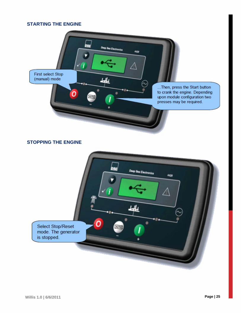
DSE Controls............................................................................................................................ 24
Starting the Engine ............................................................................................................ 25
Stopping the Engine .......................................................................................................... 25
DC Supply, Fuel, and Start Outputs ...................................................................................... 26
Analogue Sensors ................................................................................................................. 26
Magnetic Pickup .................................................................................................................... 27
CAN ...................................................................................................................................... 27
Generator/Mains Voltage Sensing ........................................................................................ 27
Digital Inputs ......................................................................................................................... 28
PC CONFIGURATION INTERFACE CONNECTOR ............................................................. 28
Typical Wiring Diagram for DSE ............................................................................................... 29
Operating The Thermostat ....................................................................................................... 30
Fan Operating Mode ............................................................................................................. 30
Displaying the temperature ................................................................................................... 30
Setting the Temperature ....................................................................................................... 30
Backlight ............................................................................................................................... 30
Thermostat Control Mode ..................................................................................................... 31
Manual/Permanent Hold Mode .......................................................................................... 31
Programmable Mode ......................................................................................................... 31
Temporary Bypass ................................................................................................................ 31
Filter Replacement Indicator ................................................................................................. 31
Battery Replacement Indicator .............................................................................................. 31
Thermostat Special Instructions Diagram ............................................................................. 32
To Complete Installation ........................................................................................................... 33
Initial Checkout and Troubleshooting .................................................................................... 33
Verify the APU for the following:............................................................................................ 33
Appendix A – Diagrams ............................................................................................................ 34
Willis 1.0 Wiring Harness Diagram ........................................................................................ 34
Manex H/C Wiring Diagram .................................................................................................. 35
Busman Box Wiring Diagram ................................................................................................ 35
Willis APU trouble shooting guide ............................................................................................ 37

Page | 3 Willis 1.0 | 6/6/2011
INSTALLATION MANUAL INTEGRATED HEAT & CLOSED LOOP COOL Although the procedures described in this manual will enable any skilled technician to install the unit, it is recommended that you contact a certified trained technician so as not to void the warranty. No specialized tools or complex system tests are required once a unit is installed. Installing the APU involves mounting the APU on the truck chassis frame. The cooling is closed loop and does not integrate with the truck. The cab controller consists of a cab display with electronic components inside. The electronic control unit and associated components mount in the sleeper compartment area for ease of control.
System Description and Benefits The Willis Power System (WPS) has several elements (or subsystems).
1. The main subsystem is the Auxiliary Power Unit (APU) an enclosure that attaches to the truck frame.
2. The electronic controller that mounts in the truck’s cab/sleeper.
Some of these capabilities include heating and air conditioning for the cab and sleeper and an alternator that replicates the trucks charging system. The APU for this specific manual has its own system separate from the truck’s engine to provide cold air for the sleeper compartment area.
WILLIS POWER SYSTEMS Always disconnect
the truck battery
before completing
any installation
procedures. Do not
reconnect, or wire
any connections
until all installation
procedures are
complete.
Please call the WPS
office for any
questions, concerns,
or assistance with
the unit installation.

Page | 4 Willis 1.0 | 6/6/2011
OVERVIEW OF INSTALLATION Unless your truck is part of a fleet, it will be different from all other installation. The installation process requires some customizations, additional preparation, and certainly some planning. The instructions in this manual may vary depending on the particular installation being performed. Remember to contact our office with any questions you may have.
Subsystems The subsystem installations in this manual are mostly independent of each other, which makes it possible and in some instances standard for two or more technicians to complete the installation in almost any order of the subsystems.
For example, the installation of the fuel system is not affected by the installation of the air system or controller wiring.
A certified professional is required to add Freon to your AC system.
Required Tools Tools needed are those typically found in any well-equipped truck repair facility. Generally, these include, but are not limited to the following:
Welding capabilities
Automobile transmission jack(s)
An air conditioner servicing and refrigerant recovery machine
Portable hoist(s) for automobile engines
Hose fitting crimping tools for A/C, oil, air and coolant fittings
Wire lug (4 gal.) crimping tool
An assortment of wire end crimping tools
Additional common parts may be required that were not packaged with the APS may include, but are not limited to the following:
Bolts
Hoses
Fillings
Lubricants
Electrical Lugs
Clamps
R-134A Cleaning Solvents
Radiator Coolants (ethylene glycol or extended life coolant)
The need for each of these parts will be identified in the appropriate sections of this manual.

Page | 5 Willis 1.0 | 6/6/2011
PREPARING FOR INSTALLATION Make sure all of the truck’s systems and subsystems are in working condition. They must operate correctly and need no further maintenance before you begin installation of the APU.
IT IS STRONGLY ADVISED THAT YOU COMPLETE THE ‘PRE-INSTALLATION INSPECTION’ CHECKLIST (APD
FORM PART NO. 170-2002) AND CONFIRM OPERATION OF EVERY SUBSYSTEM PRIOR TO INSTALLATION.
Adapting the Installation to Specific Trucks The APS installation requirements can vary slightly from truck to truck. The major variances that may affect the APS installation include, but are not limited to the following:
1. The location of the APU on the truck’s frame-rail and the subsequent need to relocate the truck’s fuel tank and/or other frame-mounted components.
2. The air tank interface.
In most instances, adapting the systems installation is a matter of convenience for the installer and does not affect system operation. Exceptions to these conveniences are noted in the detailed instructions.
Hoses, Harnesses, and Fuel Lines The most efficient way to bundle hoses, wiring harnesses, etc, is to lay them in position, then tie them together. This will reduce the chance or eliminate errors such as duplication of the same wires and/or damaged wires.
It is important to properly manage the hoses, wiring harnesses, and the fuel lines during the install. Doing so will prolong the life of the product as well as reduce errors during operation.
Prepare hoses to the following standards:
Measured correctly.
Clocked properly.
Routed cleanly.
Bundled neatly.
Protected from chafing, and heat damage
IMPORTANT: ROUTE AND INSTALL ALL HOSES BEFORE WRAPPING THEM TOGETHER. USE LOOM GUARD TO
PROTECT ALL WIRES AND HOSES. WHEN CROSSING THE CROSS MEMBERS ON THE CROSS FRAME, YOU MUST
USE AN ADEQUATE SIZED CLAMP WHEN ROUTING FROM ONE SIDE OF THE TRUCK TO THE OTHER.
DO NOT USE A ZIP TIE.
PREPPING THE APU Before the APU is mounted to the truck, you must prep the engine for installation.
1. Remove the right side panel from the engine to access the mounting posts of the j-bracket.
2. Remove the bolts for the fuel manager, and place the fuel manager at a safe place on the engine.
3. Remove the left side panel from the engine.

Page | 6 Willis 1.0 | 6/6/2011
APU Location IMPORTANT: DISCONNECT THE BATTERY PER VEHICLE MANUFACTURE INSTRUCTIONS BEFORE PERFORMING
ANY INSTALLATION PROCEDURES.
Check that the APU mounting surface or frame rail is straight and flat. The frame rail cannot be warped in a convex or concave manner. It is required that you mount to a strait and flat surface.
1. Carefully examine the truck chassis. Make sure you are mounting the APU in a healthy, non-damaged section of the frame. Establish all the possible locations the APU can attach to the truck’s frame rail (Passenger side). A minimum of 26 inches of frame rail space (in length) is required for the APU enclosure.
2. Keep note of what components or accessories you may relocate in order to install the APU to the frame rail. For example, it may be necessary to relocate a toolbox or air tank.
3. The APU should be attached to the right (passenger) side of the truck to provide safety from passing vehicles if access to the unit is required while on the road.
4. The APU may be mounted behind of the fuel tank, or under the cab, where it will replace steps or a toolbox. The APU may also be mounted behind a fairing, if one is present on the truck.
5. If the APU is mounted under the cab, steps that attach to the APU enclosure and APU cover are available from WPS, LLC. Center the APU so that the steps to the cab are convenient for cab entry.
IMPORTANT: DO NOT ATTACH THE APU ENCLOSURE CLOSER THAN THREE INCHES AWAY FROM THE TRUCK
EXHAUST. AFTER ATTACHING THE APU ENCLOSURE, THERE MUST BE ENOUGH DISTANCE BETWEEN THE GROUND
AND THE APU TO PREVENT ANY POTENTIAL CLEARANCE PROBLEMS. IF THE APU IS CENTERED PROPERLY UNDER
THE PASSENGER DOOR BEFORE DRILLING THE MOUNTING HOLES, THE STEPS THAT ATTACH TO THE APU
ENCLOSURE WILL AUTOMATICALLY ALIGN WITH THE DOOR (UNDER THE CAB MOUNTING ONLY).
Page | 7 Willis 1.0 | 6/6/2011
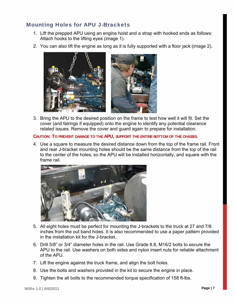
Mounting Holes for APU J-Brackets 1. Lift the prepped APU using an engine hoist and a strap with hooked ends as follows:
Attach hooks to the lifting eyes (image 1).
2. You can also lift the engine as long as it is fully supported with a floor jack (image 2).
3. Bring the APU to the desired position on the frame to test how well it will fit. Set the cover (and fairings if equipped) onto the engine to identify any potential clearance related issues. Remove the cover and guard again to prepare for installation.
CAUTION: TO PREVENT DAMAGE TO THE APU, SUPPORT THE ENTIRE BOTTOM OF THE CHASSIS.
4. Use a square to measure the desired distance down from the top of the frame rail. Front and rear J-bracket mounting holes should be the same distance from the top of the rail to the center of the holes, so the APU will be installed horizontally, and square with the frame rail.
5. All eight holes must be perfect for mounting the J-brackets to the truck at 27 and 7/8 inches from the out band holes. It is also recommended to use a paper pattern provided in the installation kit for the J-bracket.
6. Drill 5/8” or 3/4” diameter holes in the rail. Use Grade 8.8, M16/2 bolts to secure the APU to the rail. Use washers on both sides and nylon insert nuts for reliable attachment of the APU.
7. Lift the engine against the truck frame, and align the bolt holes.
8. Use the bolts and washers provided in the kit to secure the engine in place.
9. Tighten the all bolts to the recommended torque specification of 158 ft-lbs.

Page | 8 Willis 1.0 | 6/6/2011
EXHAUST INSTALLATION
1. Install the right side engine panel to the unit by installing the top bolt first, then the bottom bolt, before installing the other seven.
2. Tighten bolts in a cross pattern or some bolts may become loose.
3. Temporarily install the left side panel with only two bolts. Do not tighten bolts.
4. Hold the muffler against the panel and adjust to the best position for a custom fit.
5. Mark the places for the muffler’s mounting brackets with a marker.
6. Set the muffler aside, and remove the left panel from the engine.
7. Drill the four mounting holes into the left panel.
8. Bolt the muffler onto the left panel.
9. Install the left side engine panel (with the attached muffler) to the unit with the top bolt first, and then the bottom bolt before installing all other seven bolts. Tighten in a cross pattern.
10. Secure the fuel manager back to its original place on the left panel.
11. Remove the four nuts from the exhaust manifold.
12. Remove the gasket to access the tape.
13. Remove and discard the protective tape, and place the gasket back onto the exhaust.
14. Place the muffler pipe onto the exhaust studs, and secure with the four nuts.
15. Place the stabilizer bracket between the engine and the exhaust pipe.
16. The stabilizer bracket has 2 bolts that are secured into the engine directly above the heat exchanger block.
17. Install the u-bolt around the exhaust pipe and bolt to the stabilizer bracket in place.
18. Attach the flex pipe to the exhaust pipe and run it to the muffler.
19. Secure the flex pipe to the exhaust pipe and the muffler with a u-bolt on each side.
MUFFLER ON LEFT SIDE PANEL
STABALIZER BRACKET & U BOLT
FLEX PIPE AND U BOLTS
Page | 9 Willis 1.0 | 6/6/2011
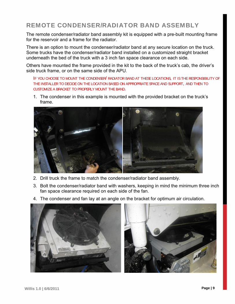
REMOTE CONDENSER/RADIATOR BAND ASSEMBLY The remote condenser/radiator band assembly kit is equipped with a pre-built mounting frame for the reservoir and a frame for the radiator.
There is an option to mount the condenser/radiator band at any secure location on the truck. Some trucks have the condenser/radiator band installed on a customized straight bracket underneath the bed of the truck with a 3 inch fan space clearance on each side.
Others have mounted the frame provided in the kit to the back of the truck’s cab, the driver’s side truck frame, or on the same side of the APU.
IF YOU CHOOSE TO MOUNT THE CONDENSER/RADIATOR BAND AT THESE LOCATIONS, IT IS THE RESPONSIBILITY OF
THE INSTALLER TO DECIDE ON THE LOCATION BASED ON APPROPRIATE SPACE AND SUPPORT, AND THEN TO
CUSTOMIZE A BRACKET TO PROPERLY MOUNT THE BAND.
1. The condenser in this example is mounted with the provided bracket on the truck’s frame.
2. Drill truck the frame to match the condenser/radiator band assembly.
3. Bolt the condenser/radiator band with washers, keeping in mind the minimum three inch fan space clearance required on each side of the fan.
4. The condenser and fan lay at an angle on the bracket for optimum air circulation.
Page | 10 Willis 1.0 | 6/6/2011
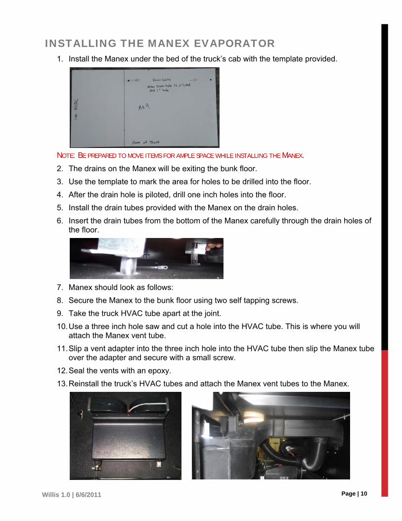
INSTALLING THE MANEX EVAPORATOR 1. Install the Manex under the bed of the truck’s cab with the template provided.
NOTE: BE PREPARED TO MOVE ITEMS FOR AMPLE SPACE WHILE INSTALLING THE MANEX.
2. The drains on the Manex will be exiting the bunk floor.
3. Use the template to mark the area for holes to be drilled into the floor.
4. After the drain hole is piloted, drill one inch holes into the floor.
5. Install the drain tubes provided with the Manex on the drain holes.
6. Insert the drain tubes from the bottom of the Manex carefully through the drain holes of the floor.
7. Manex should look as follows:
8. Secure the Manex to the bunk floor using two self tapping screws.
9. Take the truck HVAC tube apart at the joint.
10. Use a three inch hole saw and cut a hole into the HVAC tube. This is where you will attach the Manex vent tube.
11. Slip a vent adapter into the three inch hole into the HVAC tube then slip the Manex tube over the adapter and secure with a small screw.
12. Seal the vents with an epoxy.
13. Reinstall the truck’s HVAC tubes and attach the Manex vent tubes to the Manex.
Page | 11 Willis 1.0 | 6/6/2011
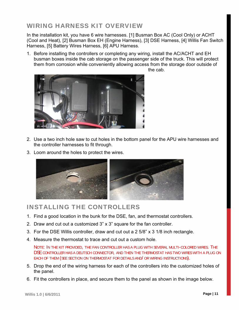
WIRING HARNESS KIT OVERVIEW In the installation kit, you have 6 wire harnesses. [1] Busman Box AC (Cool Only) or ACHT (Cool and Heat), [2] Busman Box EH (Engine Harness), [3] DSE Harness, [4] Willis Fan Switch Harness, [5] Battery Wires Harness, [6] APU Harness.
1. Before installing the controllers or completing any wiring, install the AC/ACHT and EH busman boxes inside the cab storage on the passenger side of the truck. This will protect them from corrosion while conveniently allowing access from the storage door outside of
the cab.
2. Use a two inch hole saw to cut holes in the bottom panel for the APU wire harnesses and the controller harnesses to fit through.
3. Loom around the holes to protect the wires.
INSTALLING THE CONTROLLERS 1. Find a good location in the bunk for the DSE, fan, and thermostat controllers.
2. Draw and cut out a customized 3” x 3” square for the fan controller.
3. For the DSE Willis controller, draw and cut out a 2 5/8” x 3 1/8 inch rectangle.
4. Measure the thermostat to trace and cut out a custom hole.
NOTE: IN THE KIT PROVIDED, THE FAN CONTROLLER HAS A PLUG WITH SEVERAL MULTI-COLORED WIRES. THE
DSE CONTROLLER HAS A DEUTSCH CONNECTOR, AND THEN THE THERMOSTAT HAS TWO WIRES WITH A PLUG ON
EACH OF THEM (SEE SECTION ON THERMOSTAT FOR DETAILS AND/OR WIRING INSTRUCTIONS).
5. Drop the end of the wiring harness for each of the controllers into the customized holes of the panel.
6. Fit the controllers in place, and secure them to the panel as shown in the image below.

Page | 12 Willis 1.0 | 6/6/2011
7. Access each of the controller wire harnesses from under the truck and run them to the location of the mounted busman boxes.
8. Follow the instructions for wiring on the following pages to complete the installation of the controllers.
WIRING CONNECTIONS The busman boxes are labeled AC/ACHT (Air Condition/AC & Heat) and EH (Engine Harness) to direct the proper plug-ins for your convenience.
1. Pull the controller’s wire harnesses through the holes you have drilled into the floor near the busman boxes, and extend them to the busman boxes (drill additional holes as needed).
2. Extend the APU’s wire harness along the truck frame to the cab, and pull it through the hole drilled in the floor.
Thermostat Controller Wiring The thermostat has two wires with a plug on each end and connects to both the EH and AC busman boxes. See the Thermostat Diagram for wiring instructions.
1. One of the plugs connects to the DSE orange wire plug.
2. The other plug connects to the orange wire plug on the AC busman box.
Fan Controller Wiring The fan switch has a multi-wire plug that connects to the plug with matching wires on the AC/ACHT busman box.

Page | 13 Willis 1.0 | 6/6/2011
DSE Controller Wiring The DSE has a longer wire harness with a deutsch plug on the end opposite the DSE. It also has a pink and white wired plug, and an orange wire plug with a fuse.
1. Connect the deutsch plug to the matching deutsch plug from the EH busman box.
2. Connect the orange plug to the thermostat’s orange plug.
3. The pink and white wire plug connects to the AC/ACHT orange and grey wire plug.
APU Wire Harness Inspect the APU to confirm that all wires are connected properly to the engine. Refer to the APU Wiring Harness Diagram in this manual.
APU multi-wire plug connects to the matching plug on the EH busman box.
Manex Wiring The Manex will only run while the APU is running.
1. The yellow wire with small plug and blue wire with small plug from the AC/ACHT busman connect to the rear of the Manex. These are the freeze switch wires.
2. The yellow wire with small plug and pink wire with small plug from the AC/ACHT busman connect to the Manex pressure switch.
3. The brown plug with Black, Red, Orange, and Yellow wires connect to the blower fan plug.

Page | 14 Willis 1.0 | 6/6/2011
Power Harness & EH busman Battery Cables There are two separate harnesses that connect to the truck’s battery: The Power Harness, and the Engine Harness from the busman box.
On one end of the power harness is a white wire plug and a black wire with a small eye. The other end has a white wire with an eye and fuse and a black wire with an eye.
POWER HARNESS
1. Connect the white wire plug to the AC busman box, and install the black ground wire to the bolt located on the bottom left-hand corner of the AC busman box.
2. Run the other end of the power harness through the floor to the truck’s battery.
EH BUSMAN BOX
Take the red and black wires with eyes from the EH busman box and run them along with the power harness to the truck batteries as well.
3. Complete the instructions on the following section only AFTER all wiring is complete.
WARNING: DO NOT CONNECT THE WIRES TO THE TRUCK’S BATTERY UNTIL INSTALLATION IS COMPLETE AND
YOU HAVE PERFORMED THE SAFETY AND COMPLETION CHECKLIST AT THE END OF THE MANUAL.
4. Check the following page for the wiring diagram of both busman boxes.
5. Protect any exposed wires with loom, and use an epoxy to seal the holes around the wiring in the floor of the cabin.

Page | 15 Willis 1.0 | 6/6/2011
PICTURE DIAGRAM OF WIRING HARNESSES & CONNECTIONS
EH (Engine Harness) Busman Box AC/ACHT (Air Condition Only/AC & Heat)
1. Deutsch to DSE Controller Harness
2. Multi-Wire plug to APU Harness
3. Blue & Black Wire Plug to Condenser Fan
4. Yellow & White Wire Plug for Testing
5. Red Cable with Eye to Truck Battery
6. Black Cable with Eye to Truck Battery
7. Yellow & Blue Wire with Plug to Manex
8. White Wire Plug to Power Harness
9. Orange Wire Plug to Thermostat
10. Orange & Grey Wire to DSE
11. Yellow & Pink Wire with Plug to Manex
12. Black & Green Plug (only on units with heat) connects to the electronic snap valve on the Manex or the water pump
13. Multi-wired Plug (on busman box) to Fan Controller
14. Brown Plug with Red, Black, Orange, and Yellow Wires to Manex Blower Fan
Page | 16 Willis 1.0 | 6/6/2011
INSTALLING THE FUEL SYSTEM There are two options for installing the fuel system. Speak with your provider if you are unaware of the proper installation for your specific truck type.
WARNING: DO NOT OVER TIGHTEN THE HARDWARE OR EXCEED THE RECOMMENDED TORQUE FOR THE HARDWARE AND DO NOT TWIST THE TUBE DURING INSTALLATION. DOING SO WILL CAUSE PERMANENT DEFORMATION AND RESULT IN DAMAGED AND UNUSABLE PARTS
Tools Needed ½ inch street tee
3/8 inch street tee
Number 4 strata flex
½ inch pipe to 3/8 bushing
3/8 male pipe to number four JIC
Check valve
APU Fuel hose
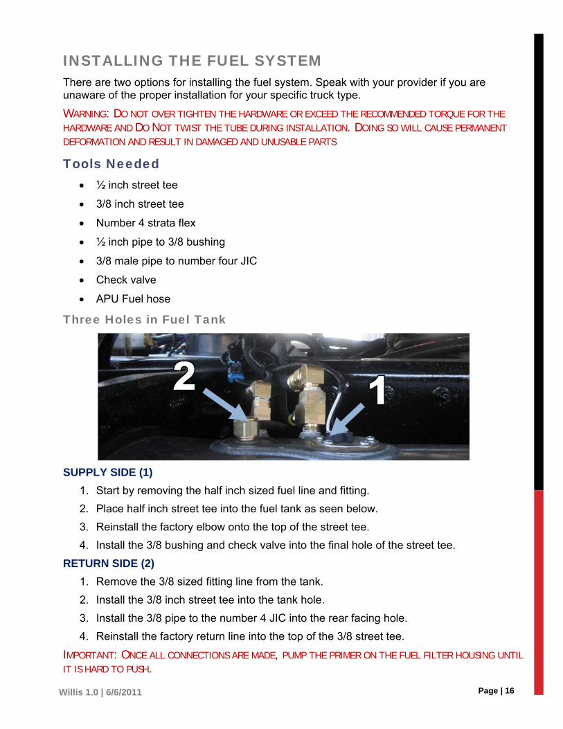
Three Holes in Fuel Tank
SUPPLY SIDE (1)
1. Start by removing the half inch sized fuel line and fitting.
2. Place half inch street tee into the fuel tank as seen below.
3. Reinstall the factory elbow onto the top of the street tee.
4. Install the 3/8 bushing and check valve into the final hole of the street tee.
RETURN SIDE (2)
1. Remove the 3/8 sized fitting line from the tank.
2. Install the 3/8 inch street tee into the tank hole.
3. Install the 3/8 pipe to the number 4 JIC into the rear facing hole.
4. Reinstall the factory return line into the top of the 3/8 street tee.
IMPORTANT: ONCE ALL CONNECTIONS ARE MADE, PUMP THE PRIMER ON THE FUEL FILTER HOUSING UNTIL IT IS HARD TO PUSH.

Page | 17 Willis 1.0 | 6/6/2011
Two Holes in Fuel Tank Before installing the fuel tube, measure the diameter of the fuel tank. In the kit you will get a 24” peace of ¼” tubing, this is going to become the fuel supply to the APU.
1. If the tank is 24” in diameter then you should cut approximately 2” off the tube.
2. Now it is time to assemble the fuel block itself as seen in figure 1. When putting the block together you must use a high temp thread lock sealant on all threads except on the compression fitting where the pick-up tube is inserted.
3. Once it is tight, remove the lower end of the compression fitting with the tube and the boss should be tight on the tube.
4. Remove the old fuel vent from the tank (make sure you have cleaned around the old vent so no dirt falls into the tank) using a 7/8 end wrench.
DO NOT DROP THE TUBE INTO THE TANK.
5. Hold the tube like seen in the image 2 then reattach the top of the fuel block.
6. Tighten the compression fitting back down and then thread the block into the vent hole on the tank.
THE VENT THAT IS REMOVED FROM THE TANK IS
NOT USED IN THIS FUEL BLOCK YOU MUST GET A
SHORT VENT; THE PETERBILT PART NUMBER IS
2113-1.
7. When starting to thread the block into tank you may have to put some SLIGHT bends in the tube to aid in getting the threads to start.
8. Now it’s time to hook the pull and return lines to the block, in the fuel block the top ¼” fitting will always be the return, and the lower will be the pull.
9. On the APU, the fuel in/pull will always be to the lower right of the deutsch plug and the return is to the lower left.
10. Once all connections are made then pump the primer on the fuel filter housing till it is hard to push.
IMAGE 2
IMAGE 1
IMAGE 3
IMAGE 2

Page | 18 Willis 1.0 | 6/6/2011
CONNECTING COOLANT HOSES FOR INTEGRATED HEAT Below is the diagram for the fluid circulation in the hot and cold closed loop APU. The hoses are connected from the APU as follows. All trucks vary. The following directions are offered as a guide and should not be directly imitated. Use the information as a reference to know what to look for.
You will need 3/4” and 5/8” silicone hoses and corresponding hose clamps. Before cutting the hoses to measurement, it is recommended to run the hoses from each location under the truck before cutting them to size.
Make sure you have enough hose length for each line, in order to run them together along the truck’s frame.
NOTE: DO NOT HANG THE HOSES LOOSELY UNDERNEATH THE TRUCK. SECURE ALL HOSES
TOGETHER WITH ZIP TIES SO THAT THEY ARE SECURED TIGHTLY AND WILL NOT RUB AGAINST
EACH OTHER FROM THE TRUCK VIBRATIONS. SECURE ALL HOSES WITH THE PROPER HOSE
CLAMPS.
1. Remove the radiator tank hard tube from the truck’s engine.
2. Examine the hose for the best place to install the upper radiator hose valve provided in the installation kit.
NOTE: THE HOLE WILL BE OVAL TO ALLOW THE UNION TO BE INSERTED IN AN ANGLE. THE
HOLE SHOULD BE LOCATED IN SUCH A POSITION THAT THE COOLANT FLOW THROUGH THE
UNION IS AIMED AT THE RADIATOR, BLENDING WITH THE FLOW OF THE COOLANT ALREADY
FLOWING THROUGH THE HARD TUBE.
3. Drill the hard tube for the union that will be welded into the tube.

Page | 19 Willis 1.0 | 6/6/2011
4. Weld the union into the hard tube. Let cool to the touch. Check for leaks. Prime and paint the union and the welded area.
5. Re-install the hard tube with the union. Install the shut-off valve and the hose nipple in the union (use thread sealant).
6. Attach the five coolant hoses to the APU.
7. Remove and discard the heater hoses running from the truck engine to the cab heater and sleeper heater. They will be replaced with new hoses running to the APU.
8. Attach the 5/8” hose to the heater core on the truck engine.
9. Run the hoses along the inside frame of the truck with the radiator hose.
10. Install the 5/8” hose to the sleeper heater core.
11. Use the kit-supplied spring clamps on all heater hoses.
12. Route each hose to its location on the truck. Cut to length and secure the hose with fittings.

Page | 20 Willis 1.0 | 6/6/2011
13. Re-install the upper radiator hose onto the truck engine.
14. Take the ¾” hose and cover it in high temperature loom for protection.
15. Calculate the distance from the APU unit to the truck.
NOTE: IT IS BEST TO PHYSICALLY RUN THE HOSE UNDERNEATH THE TRUCK TO ESTIMATE THE LENGTH YOU NEED
BEFORE CUTTING THE HOSE TO PREVENT CUTTING IT TOO SHORT.
16. Run the hose along the frame of the truck underneath the cab.
17. Find the best place to run the hose around and/or over the motor so that it can reach the upper radiator hose valve.
18. Attach the hose to the upper radiator hose valve, and secure carefully with a hose clamp.
19. Tie the hose down in the truck’s engine away from anything that may cause damage to the hose, or that the hose may cause damage to.
20. Secure the hose with y-ties within the engine, and check the line along the inside frame of the truck to the APU. Connect hose to the top spout of the unit.
TIP: WAIT UNTIL YOU’VE RUN ALL THE HOSES THAT WILL BE FROM THE ENGINE TO THE APU ALONG THE INSIDE FRAME OF THE TRUCK BEFORE TYING THEM DOWN. THIS ALLOWS YOU TO TIE ALL OF THEM DOWN TOGETHER IN A BUNDLE.
Radiator Band Hoses 1. Connect a 3/4” hose to the top, COOLANT IN hose inlet on the APU and secure with a
hose clamp.
2. Run the hose from the APU to the Radiator’s COOLANT IN hose inlet.
3. Connect the 5/8” hose to the fifth (bottom) hose inlet on the APU, secure with a hose clamp, and run it to the radiator’s hose inlet for coolant.
4. The third hose inlet connects the radiator band to the reservoir with a 5/8” hose.
Manex Hoses Holes should be pre-drilled into the floor of the cabin during the Manex installation to run the hoses through from the APU.
1. Connect a 5/8” hose to the third, CAB HTR (center) hole on the APU.
2. Run the hose along the frame of the truck under the cab to the Manex.
3. If you don’t already have a pre-drilled hole underneath the cab from the installation of the Manex, drill the hole now.
4. Connect another 5/8” hose run from the hose inlet on the Manex.
5. Run the hose back to the APU where it will connect to the same hose from the radiator hose using a tee, back to the COOLANT IN hose inlet on the APU.
6. Cover all hoses with high temperature lube to protect them from heat, debris, and wear.
7. Gather hoses together along the truck’s frame and use zip ties to secure them to the frame tight enough so that there is no room for friction from the truck’s vibration.

Page | 21 Willis 1.0 | 6/6/2011
CONNECTING THE AC LINES (CLOSED LOOP COOL) The proper fittings for both the AC unit and the compressor are crimped on site at installation. Make sure you have the proper tools available before completing the following steps.
The compressor has a size 8 and 10 hose fitting, and both AC condenser and Manex have a size 6 and 8 hose fitting. The dryer has two size 6 hose fittings on each side. Run the hoses to/from the compressor through the rear panel of the APU.
NOTE: HOLES SHOULD BE DRILLED THROUGH THE FLOOR OF THE CABIN DURING THE MANEX INSTALL FOR THE
HOSES FROM THE APU TO ENTER.
1. All hoses must be covered in high temperature loom for protection from heat, wear, and corrosion before installing.
2. The Size 8 hose fitting from the compressor connects to the size 8 hose fitting on the condenser with a size 8 hose (blue).
3. The size 6 hose fitting from the condenser connects to the size 6 hose fitting on the Dryer with a size 8 hose (green).
NOTE: THE DRYER IS DIRECTIONAL WITH THE ARROW ON THE TOP FACING IN THE DIRECTION OF THE FLOW OF
FREON.
4. The size 6 hose fitting from the dryer connects to the size 6 hose fitting on the Manex with a size 8 hose (Orange).
5. The size 8 hose fitting from the Manex connects to the size 10 hose fitting on the compressor with a size 10 hose (purple).
Page | 22 Willis 1.0 | 6/6/2011
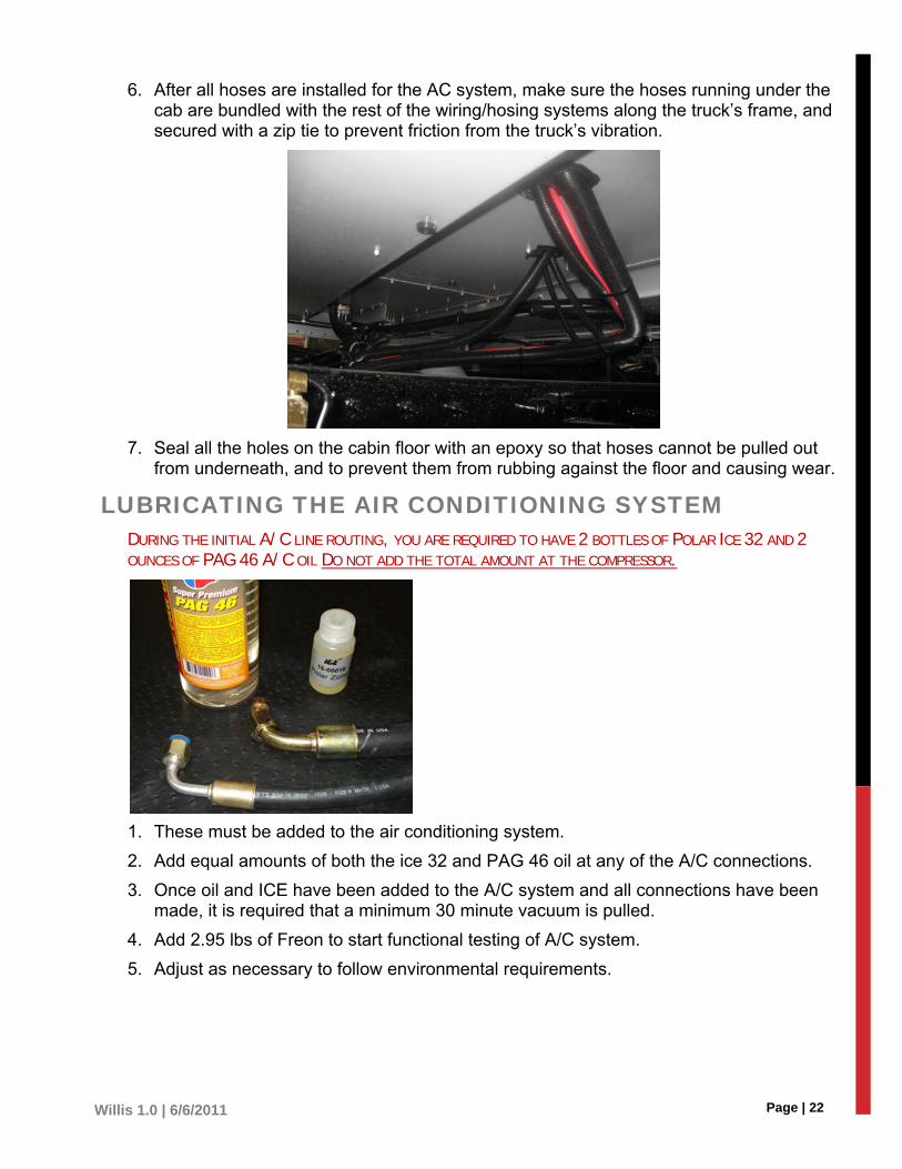
6. After all hoses are installed for the AC system, make sure the hoses running under the cab are bundled with the rest of the wiring/hosing systems along the truck’s frame, and secured with a zip tie to prevent friction from the truck’s vibration.
7. Seal all the holes on the cabin floor with an epoxy so that hoses cannot be pulled out from underneath, and to prevent them from rubbing against the floor and causing wear.
LUBRICATING THE AIR CONDITIONING SYSTEM DURING THE INITIAL A/C LINE ROUTING, YOU ARE REQUIRED TO HAVE 2 BOTTLES OF POLAR ICE 32 AND 2
OUNCES OF PAG 46 A/C OIL DO NOT ADD THE TOTAL AMOUNT AT THE COMPRESSOR.
1. These must be added to the air conditioning system.
2. Add equal amounts of both the ice 32 and PAG 46 oil at any of the A/C connections.
3. Once oil and ICE have been added to the A/C system and all connections have been made, it is required that a minimum 30 minute vacuum is pulled.
4. Add 2.95 lbs of Freon to start functional testing of A/C system.
5. Adjust as necessary to follow environmental requirements.

Page | 23 Willis 1.0 | 6/6/2011
INSTALLING THE DSE4410 Dimension
180mm x 116mm x 42mm (7.1” x 4.6” x 1.7”)
Panel Cut-out
154mm x 98mm (6” x 3.9”)
FIXING CLIPS
The module is held into the panel fascia using the supplied fixing clips.
1. Withdraw the fixing clip screw (turn anticlockwise) until only the pointed end is protruding from the clip.
2. Insert the three ‘prongs’ of the fixing clip into the slots in the side of the 3000 series module case.
3. Pull the fixing clip backwards (towards the back of the module) ensuring all three prongs of the clip are inside their allotted slots.
4. Turn the fixing clip screws clockwise until they make contact with the panel fascia.
5. Turn the screws a little more to secure the module into the panel fascia. Care should be taken not to over tighten the fixing clip screws.
NOTE: USE ANTI-VIBRATION MOUNTING FOR PANEL IN CASE OF EXCESSIVE VIBRATION.
OPTIONAL SILICON SEALING GASKET
The optional silicon gasket provides improved sealing between the module and the panel fascia.
The gasket is fitted to the module before installation into the panel fascia.
Take care to ensure the gasket is correctly fitted to the module to maintain the integrity of the seal.
NOTE: IN LINE WITH OUR POLICY OF CONTINUAL DEVELOPMENT, DEEP SEA ELECTRONICS, RESERVE THE RIGHT TO CHANGE SPECIFICATION WITHOUT NOTICE.
DSE Wiring Diagram Ground Wire – 25, 1 (Black)
Battery – 2 (Red)
Fuel Solenoid – 3 (Yellow)
Starter Wire – 4 (Orange)
Glow Plugs – 6 (Purple)
Oil Pressure Sensor – 11 (Brown)
High Temperature Sensor – 12 (Blue)
Speed Sensor – 14 (Dark Green)
Speed Sensor – 15 (Light Green)
Page | 24 Willis 1.0 | 6/6/2011
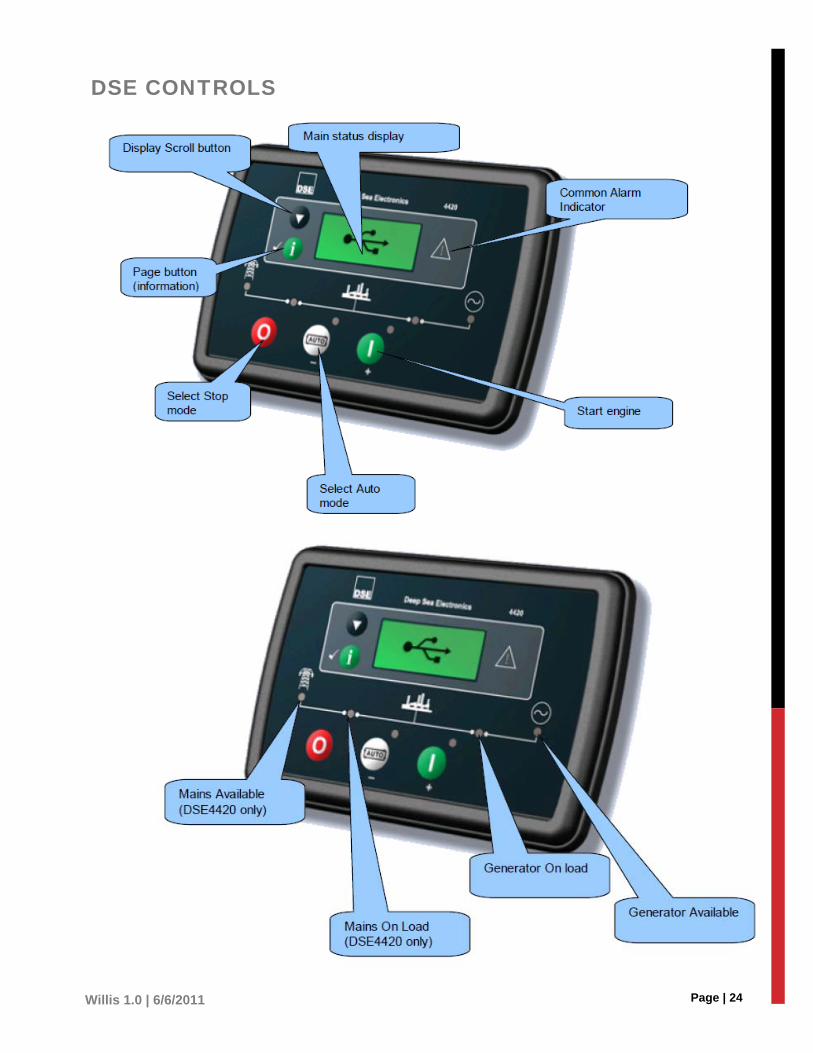
DSE CONTROLS
Page | 25 Willis 1.0 | 6/6/2011
STARTING THE ENGINE
STOPPING THE ENGINE

Page | 26 Willis 1.0 | 6/6/2011
DC Supply, Fuel, and Start Outputs
PIN DESCRIPTION
CABLE SIZE
NOTES
1 DC Plant Supply Input (Negative)
2.5mm² AWG 13
2 DC Plant Supply Input (Positive)
2.5 mm² AWG 13
(Recommended Maximum Fuse 15A anti-surge)
Supplies the module (2A anti-surge requirement) and all output relays
3 Output A (FUEL) 1.0mm² AWG 18
Plant Supply Positive from terminal 2. 3 Amp rated. Normally used for FUEL control.
4 Output B (START) 1.0mm² AWG 18
Plant Supply Positive from terminal 2. 3 Amp rated. Normally used for START control.
5 Charge fail / excite
2.5mm²
AWG 13
Do not connect to ground (battery negative).
If charge alternator is not fitted, leave this terminal disconnected.
6 Output C
1.0mm²
AWG 18
Plant Supply Positive from terminal 2. 3 Amp rated.
Normally used for Generator load switch control.
7 Output D 1.0mm²
AWG 18
Plant Supply Positive from terminal 2. 3 Amp rated.
Normally used for Mains load switch control (DSE4420)
8 Output E 1.0mm²
AWG 18
Plant Supply Positive from terminal 2. 3 Amp rated.
9 Output F 1.0mm²
AWG 18
Plant Supply Positive from terminal 2. 3 Amp rated.
Analogue Sensors PIN DESCRIPTION CABLE NOTES
10 Sensor Common Return 0.5mm²
AWG 20
Return feed for sensor*
11 Fuel Level input 0.5mm²
AWG 20
Connect to Fuel Level sensor

Page | 27 Willis 1.0 | 6/6/2011
Magnetic Pickup (MODEL 3110-XX-01) Model 3110-xx-01 (Magnetic pickup enabled module)
PIN DESCRIPTION CABLE NOTES
12 Magnetic pickup Positive 0.5mm² AWG 20
Connect to Magnetic Pickup device
13 Magnetic pickup Negative 0.5mm² AWG 20
Connect to Magnetic Pickup device
14 Configurable digital input C 0.5mm² AWG 20
Do not connect the other end to earth!
CAN
Screened 120W impedance cable specified for use with CAN must be used for the CAN link and the Multi-set comms link. DSE stock and supply Belden cable 841 which is a high quality 120W impedance cable suitable for CAN use (DSE part number 016-030).
PIN DESCRIPTION CABLE NOTES
12 Configurable digital input A 0.5mm² AWG 20
Use only 120� CAN approved cable
13 Configurable digital input B 0.5mm² AWG 20
Use only 120� CAN approved cable
14 CAN 0.5mm² AWG 20
Use only 120� CAN approved cable
Generator/Mains Voltage Sensing PIN DESCRIPTION CABLE NOTES
15 Generator L1 (U) voltage monitoring
1.0mm²
AWG 18
Connect to generator L1 (U) output (AC) (Recommend 2A fuse)
16 Generator Neutral (N) input
1.0mm²
AWG 18
Connect to generator Neutral terminal (AC)
17 Mains L1 (R) voltage monitoring
1.0mm²
AWG 18
Connect to Mains L1 (R) output (AC) (Recommend 2A fuse)
18 Mains L2 (S) voltage monitoring
1.0mm²
AWG 18
Connect to Mains L2 (S) output (AC)
(Recommend 2A fuse)
19 Mains 31 (T) voltage monitoring
1.0mm²
AWG 18
Connect to Mains L3 (T) output (AC)
(Recommend 2A fuse)
20 Mains Neutral (N) input 1.0mm²
AWG 18 Connect to Mains Neutral terminal (AC)
Page | 28 Willis 1.0 | 6/6/2011
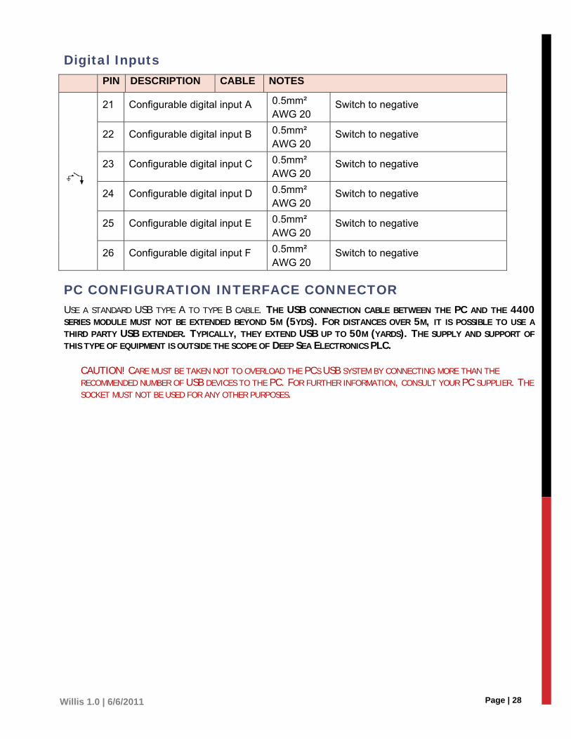
Digital Inputs PIN DESCRIPTION CABLE NOTES
21 Configurable digital input A 0.5mm² AWG 20
Switch to negative
22 Configurable digital input B 0.5mm² AWG 20
Switch to negative
23 Configurable digital input C 0.5mm² AWG 20
Switch to negative
24 Configurable digital input D 0.5mm² AWG 20
Switch to negative
25 Configurable digital input E 0.5mm² AWG 20
Switch to negative
26 Configurable digital input F 0.5mm² AWG 20
Switch to negative
PC CONFIGURATION INTERFACE CONNECTOR USE A STANDARD USB TYPE A TO TYPE B CABLE. THE USB CONNECTION CABLE BETWEEN THE PC AND THE 4400 SERIES MODULE MUST NOT BE EXTENDED BEYOND 5M (5YDS). FOR DISTANCES OVER 5M, IT IS POSSIBLE TO USE A THIRD PARTY USB EXTENDER. TYPICALLY, THEY EXTEND USB UP TO 50M (YARDS). THE SUPPLY AND SUPPORT OF THIS TYPE OF EQUIPMENT IS OUTSIDE THE SCOPE OF DEEP SEA ELECTRONICS PLC.
CAUTION! CARE MUST BE TAKEN NOT TO OVERLOAD THE PCS USB SYSTEM BY CONNECTING MORE THAN THE RECOMMENDED NUMBER OF USB DEVICES TO THE PC. FOR FURTHER INFORMATION, CONSULT YOUR PC SUPPLIER. THE SOCKET MUST NOT BE USED FOR ANY OTHER PURPOSES.
Page | 29 Willis 1.0 | 6/6/2011
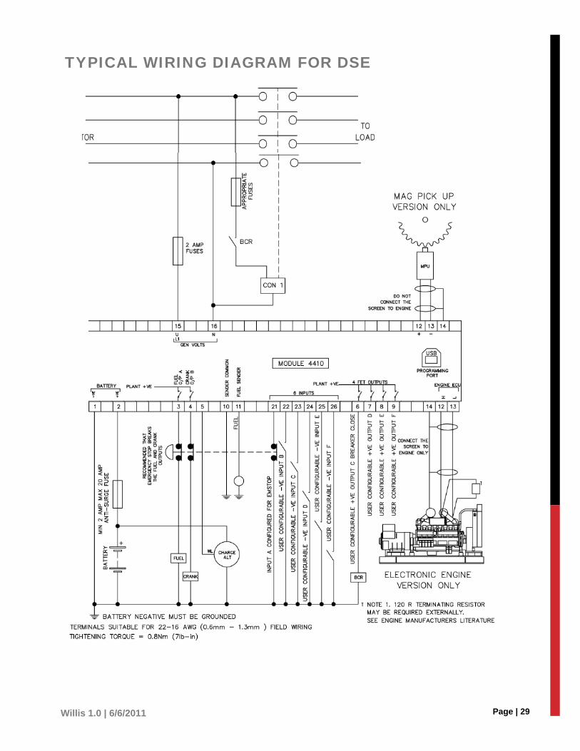
TYPICAL WIRING DIAGRAM FOR DSE

Page | 30 Willis 1.0 | 6/6/2011
OPERATING THE THERMOSTAT For more information, view the instruction guide that accompanies your thermostat.
Use the selector switch to place the system in cooling mode or set mode to off.
NOTE: NOTE: YOU MUST HAVE A CLOSED LOOP (CIRCUIT) PROGRAM TO EFFECTIVELY USE THE THERMOSTAT CONTROLS. IF YOU HAVE A CLOSED LOOP AC SYSTEM ONLY, THEN ONLY THE AC CONTROLS ARE AFFECTED BY THE THERMOSTAT. IF YOU HAVE A CLOSED LOOP HEAT AND AC SYSTEM THEN BOTH HEAT AND AC CONTROLS ARE AFFECTED BY THE THERMOSTAT.
Fan Operating Mode Use the selector switch to set the fan to automatic mode or continuous mode.
NOTE: THIS SWITCH IS NOT USED IN A 2-WIRE INSTALLATION AS THE FAN IS NOT CONNECTED TO THE THERMOSTAT IN THIS TYPE OF INSTALLATION.
Auto The fan operates only when the cooling system is on (typical setting).
On The fan operates continuously. Use this setting to improve air circulation and air cleaning.
Displaying the temperature The actual temperature is normally displayed. To view the set point, press once on one of the buttons. The set point is displayed for 5 seconds along with the arrow icon.
NOTE: PRESSING EITHER OF THE BUTTONS MORE THAN ONCE WILL CHANGE THE SET POINT.
Setting the Temperature Press one of the up or down buttons until the desired temperature is displayed.
Backlight The display illuminates for 12 seconds when the backlight button or any of the buttons are pressed.
Page | 31 Willis 1.0 | 6/6/2011
Thermostat Control Mode MANUAL/PERMANENT HOLD MODE
This mode maintains the temperature at a fixed set point. To place the thermostat in this mode, press [Mode]. The house icon will disappear.
PROGRAMMABLE MODE
This mode maintains the temperature according to the energy-saving schedule. To place the thermostat in this mode, press [Mode]. The current period will be displayed. The four possible periods are:
Wake Up
Leave for work
Return Home
Sleep
Temporary Bypass If you modify the set point (using the buttons) when the thermostat is in Programmable mode, the thermostat will use the new set point for the next 2 hours. The house icon flashed during the bypass. Afterwards, the thermostat will return to the temperature setting of the period currently underway.
Filter Replacement Indicator After 500 hours of operation, an icon appears to indicate that the filter needs replacement. Once the filter is replaced, press [Filter] for 3 seconds to remove the icon and reset the counter.
Battery Replacement Indicator Install fresh batteries immediately when the icon starts flashing. The icon flashes for 120 days before the batteries are depleted. You should replace batteries once a year before leaving home for more than a month even if the icon has not appeared.
After replacing the batteries, set the time, day and date). However, the temperature and program settings are saved and do not need to be re-entered.
WARNING: BEFORE REMOVING THE BATTERIES, PLACE THE SYSTEM SWITCH ON THE THERMOSTAT TO OFF. OTHERWISE, THE HEATING/COOLING UNIT MIGHT STILL BE RUNNING EVEN AFTER THE BATTERIES ARE REMOVED.

Page | 32 Willis 1.0 | 6/6/2011
Thermostat Special Instructions Diagram The thermostat must be set to HE (Heat Electric) instead of HG (Heat Gas).
If thermostat is not set to HE, you can remove the electronic tab or from the prongs and replace it on the proper setting.
1. Place the power input from the (DSE) controller harness to G.
2. The output power goes into the orange wire on the bottom of the relay board.
Note: Thermostat interrupts wire from controller harness to relay board.

Page | 33 Willis 1.0 | 6/6/2011
TO COMPLETE INSTALLATION Once all the subsystems are installed, the final step can be completed. This is to secure all hoses. Hoses should be bundled and secured with tie wraps or clamps as appropriate. There should not be any twists or sharp bends. No hose should be under tension that might contribute to failure of a fitting. Check for areas of possible chafing in the hose runs. Check one more time that hoses are connected correctly. Check all hoses for possible heat damage. If damage has occurred, move or protect these hoses.
If any hose is a little long, make sure it is looped up and does not sag. Secure any such upward curve to make sure it does not become a sag in the hose.
IMPORTANT: RECONNECT THE BATTERY! MAKE FINAL APU TO BATTERY CONNECTIONS!
Initial Checkout and Troubleshooting Once the APS is completely installed, it needs to be inspected before the APU can be started. Remove the fairing from the APU. The following items need to be visually inspected before proceeding to the next steps:
Attachment of the APU (bolts tight, enclosure clearance OK and all connections to end plate are secured).
All hose tie wraps and other clamps are in place.
Coolant System (coolant is replaced and valves open). Check for leaks, and add coolant to top off system.
Fuel System (connected correctly to main fuel tank, line clearances).
Pneumatic Compressor (lines connected).
Air Conditioning.
Oil Pump (valve open).
Electrical System (wire wraps, connected to right terminals, no chafing). Electronic Control (wiring correct).
Verify the APU for the following:
WARNING!!! DO NOT OVERFILL! THE CRANK-CASE HAS A CAPACITY OF 3 ½ U.S. QUARTS.
APU crank case is filled.
All valves open.
Fuel in lines… use primer pump: Check throttle for operation and settings.
Next, start the truck engine and run it (at 1200 RPM) for not less than twenty minutes.
NOTE: THIS WILL BLEED AIR FROM THE COOLANT SYSTEM. YOU WILL NEED TO ADD 1 TO 3 GALLONS OF
COOLANT TO THE TRUCK.
Prime and start the APU, and while it is running with the cover off, check for leaks everywhere in the system. Check the low idle for 1500 RPM and the high idle at 2300 to 2400 RPM (with no load).
Recheck the hoses with the APU running to make sure there is no vibration that could result in hose chafing. No leaks, now is the time to reinstall the fairings and covers

Page | 34 Willis 1.0 | 6/6/2011
APPENDIX A – DIAGRAMS On Following Pages Are Diagrams
Motor Wiring Diagram
Manex H/C Wiring Diagram
Pin Out Diagram A-Cab Dash Control Comm Line Diagram A-Overall System Diagram
Willis APU Manual Aug, 28th 2009: B Collins
Willis 1.0 Wiring Harness Diagram Note: All wires run into 12 pin plug

Page | 35 Willis 1.0 | 6/6/2011
Manex H/C Wiring Diagram
Busman Box Wiring Diagram

Page | 36 Willis 1.0 | 6/6/2011

Page | 37 Willis 1.0 | 6/6/2011
WILLIS APU TROUBLE SHOOTING GUIDE
Symptom Check #1 Additional Checks Probable Cause Actions
APU does not start
Display does not have power
Check fuses and mega fuse block
Fuse / Relay link broken
Replace fuse and relay if necessary. Look for loose connections or corrosion in wire
Verify correct voltage at (+) post on APU
Bad battery or loose connection 12 volts minimum required
Are connections clean Road dirt / tar Clean connections
Check supply power at ECU
This is pin(2) at the 12 pin male connector System voltage
If voltage checks OK Bad ECU Replace ECU
Before installing new ECU
Verify new ECU has new battery
Display has power
Check F1 fuse and R1 relay (Power at Starter)
Fuse / Relay link broken
Replace fuse and relay if necessary. Look for loose connections or corrosion in wire
If OK, check voltage at starter wire when activated
Potential Bad Starter
If voltage is system voltage then replace Starter
If voltage is not system voltage then
Potential Bad ECU Check output voltage at ECU
Pin #4 at the 12 pin male connector
If no voltage…replace ECU
Break in wiring harness or connection
Find and or replace wiring harness

Page | 38 Willis 1.0 | 6/6/2011
APU cranks but will not start
Starter
Check Fuse F‐1, Relay R1
Replace fuse and relay if necessary. Look for loose connections or corrosion in wire
Glow Plugs
Check Fuse F‐7, Relay R4
Replace fuse and relay if necessary. Look for loose connections or corrosion in wire
Shut down Solenoid
Check Fuses F‐3, F‐5, Relay R2, R3
Replace fuse and relay if necessary. Look for loose connections or corrosion in wire
If OK then put in start mode and check voltage at glow plugs
If not system voltage; then broken wire. Find and replace
Verify shut down solenoid is working
Visual inspection
Check oil pressure switch
Bad Switch Replace Oil pressure switch
Check temp sender
Bad Temp Sender
Replace Temp Sender
Check resistance
Bad RPM sensor
With no power 135 ohms resistance
Check resistance and proper set of speed sensor
Dirt / Oil causing incorrect RPM reading
Remove RPM sensor and clean. Install to finger tight against the flywheel teeth and back off 1/4 turn. Tighten secure nut.
Exhaust Check for blockage Visual
Lacks Fuel Check for fuel supply
Air blockage in line from fuel pump
Pull pump supply line and observe fuel flow
Check fuel filter supply
Bad or blocked filter
Replace fuel filter
Lacks Air Check air filter
Blockage in air delivery
Repair and or replace

Page | 39 Willis 1.0 | 6/6/2011
Low engine power or bogs down
Check air filter for improper cleaning and replacement Replace air filter
Check fuel supply Find blockage and remove
Check fuel filter Replace fuel filter
Engine starts but will not run to operating RPM
Review controller icon list for fault indication
Throttle Solenoid
Check fuse F-9 and relay R-5
Replace fuse and relay if necessary. Look for loose connections or corrosion in wire
Check power at throttle solenoid and test solenoid with VOM
System voltage
Check throttle solenoid travel by resistance ohms check
Open should be low ohms 2 or less Closed will be 18- 21 ohms
APU starts but major components are inoperable
Check drive belts visually Replace
AC inoperable
Check in-line fuses
Replace fuse and relay if necessary. Look for loose connections or corrosion in wire
Check belt on AC compressor Replace
Check power at AC clutch connection
System voltage
Check R134 level Add additional if necessary
Check for evidence of R134 leakage at all AC fittings…this is the most common cause of AC failure
Yellowish color at fitting crimp or threads

Page | 40 Willis 1.0 | 6/6/2011
APU will not go to high idle
Throttle Solenoid
Check fuse F‐9 and relay R‐5
Replace fuse and relay if necessary. Look for loose connections or corrosion in wire
Check power at throttle solenoid and test solenoid with VOM
System voltage
Check throttle solenoid travel by resistance ohms check
Open should be low ohms 2 or less Closed will be 18‐ 21 ohms
WPS "Willie" APU
In Cab A/C switch connection
Fix connection or replace switch
APU alternator not charging
Check drive belt Broken belt Replace alternator belt
Check alternator output to system voltage 14 volts+
Bad Alternator Replace alternator
APU A/C compressor not working
Check drive belt Broken belt Replace belt
Check for system voltage at clutch wire
A/C clutch Replace A/C compressor and clutch
Check for freon leakage
Road vibration causing leak at fitting or hoses
Replace fittings / hoses and pull vacuum to verify proper seal.
APU A/C on not cooling
A/C charge Check for leaks Road vibration causing leak at fitting or hoses
Replace fittings / hoses and pull vacuum to verify proper seal.
A/C fan inoperable
Check in‐line fuse / breaker and relay
Loose connections
Replace fuse and relay if necessary. Look for loose connections or corrosion in wire
A/C high pressure switch
Check for power going through if over 300psi
Replace if no system voltage
Oil pressure switch
Check for power going through if truck engine off
Replace if no system voltage
Solenoid Check that solenoid is switching
Replace if not switching

Page | 41 Willis 1.0 | 6/6/2011
Bunk Controller
Unit shuts down
Check DC supply voltage is not above 35 Volts or below 9 Volts Check the operating temperature is not above 160°F. Check the DC fuse.
Replace fuse and relay if necessary. Look for loose connections or corrosion in wire
Intermittent Magnetic Pick‐up sensor fault
Ensure that Magnetic pick‐up screen only connects to earth at one end, if connected at both ends, this enables the screen to act as an aerial and will pick up random voltages. Check pickup is correct distance from the flywheel teeth.
Reset speed sensor to proper depth
Low oil Pressure fault operates after engine has fired
Check engine oil pressure. Check oil pressure switch/sensor and wiring. Check configured polarity (if applicable) is correct (i.e. Normally Open or Normally Closed)
Replace oil sensor switch
High engine temperature fault operates after engine has fired.
Check engine temperature. Check switch/sensor and wiring. Check configured polarity (if applicable) is correct (i.e. Normally Open or Normally Closed)
Replace temp sensor
Fail to Start is activated after preset number of attempts to start
Check wiring of fuel solenoid. Check fuel. Check battery supply. Check battery supply is present on the Fuel output of the module.
System voltage: Replace wire to component or component
Pre‐heat inoperative
Check wiring to engine heater plugs. Check battery supply. Check battery supply is present on the Pre‐heat output of module. Check pre‐heat configuration is correct.
System voltage: Replace wire to component or component
Starter motor inoperative
Check wiring to starter solenoid. Check battery supply. Check battery supply is present on the Starter output of module.
System voltage: Replace wire to component or component


![Members: [ Cheong Jiawei 4D04 ][Douglas Lee 4D06] [Kenny Wong 4D29][Law Chun Yin 4C12] [Yeow Kai Yao 4C34]](https://static.fdocuments.in/doc/165x107/56649e295503460f94b16d6f/members-cheong-jiawei-4d04-douglas-lee-4d06-kenny-wong-4d29law-chun.jpg)


![Auxilary Boiler Basuki Inc]](https://static.fdocuments.in/doc/165x107/546a38cdaf795976298b45ab/auxilary-boiler-basuki-inc.jpg)