WiLink 8 WLAN Features (Rev. A) - TI.com · WiLink™ 8 WLAN Features User's Guide ... 2.9 Wi-Fi...
44
WiLink™ 8 WLAN Features User's Guide Literature Number: SWRU423A July 2015–Revised May 2016
Transcript of WiLink 8 WLAN Features (Rev. A) - TI.com · WiLink™ 8 WLAN Features User's Guide ... 2.9 Wi-Fi...

WiLink™ 8 WLAN Features
User's Guide
Literature Number: SWRU423AJuly 2015–Revised May 2016

2 SWRU423A–July 2015–Revised May 2016Submit Documentation Feedback
Copyright © 2015–2016, Texas Instruments Incorporated
Table of Contents
Contents
1 Introducion.......................................................................................................................... 51.1 Scope ...................................................................................................................... 51.2 Acronyms Table .......................................................................................................... 51.3 WiLink 8 Specification ................................................................................................... 7
2 General Features.................................................................................................................. 82.1 Supported Rates ......................................................................................................... 82.2 High-Throughput (HT) Features........................................................................................ 92.3 Quality of Service (QoS) ............................................................................................... 122.4 Protection Types ....................................................................................................... 132.5 Suspend and Resume ................................................................................................. 142.6 WoW (Wake on WLAN)................................................................................................ 142.7 Set TX Power ........................................................................................................... 152.8 5-GHz Antenna Diversity .............................................................................................. 152.9 Wi-Fi – Bluetooth/Bluetooth Smart Coexistence.................................................................... 162.10 Wi-Fi – ZigBee Coexistence........................................................................................... 162.11 Accurate Synchronization Over Wi-Fi................................................................................ 17
3 Single Role: Station ............................................................................................................ 173.1 Scanning ................................................................................................................. 173.2 Connection............................................................................................................... 193.3 Disconnection ........................................................................................................... 213.4 DHCP Client............................................................................................................. 223.5 Security .................................................................................................................. 223.6 Filtering................................................................................................................... 223.7 Auto ARP ................................................................................................................ 233.8 Preferred Networks (Profiles) ......................................................................................... 233.9 Power-Save Mode ...................................................................................................... 243.10 Power-Save Delivery Protocols....................................................................................... 253.11 Keep-Alive Mechanism................................................................................................. 253.12 Smart Config ............................................................................................................ 253.13 Regulatory Domain ..................................................................................................... 263.14 DFS Slave (Channel Switch).......................................................................................... 263.15 Roaming ................................................................................................................. 26
4 Single Role: AP .................................................................................................................. 284.1 Connection............................................................................................................... 284.2 Hidden SSID............................................................................................................. 284.3 Security .................................................................................................................. 284.4 Regulatory Domain ..................................................................................................... 294.5 AP Scan.................................................................................................................. 294.6 Automatic Channel Selection (ACS) ................................................................................. 294.7 Maximum Connected Stations ........................................................................................ 294.8 Aging ..................................................................................................................... 30
www.ti.com
3SWRU423A–July 2015–Revised May 2016Submit Documentation Feedback
Copyright © 2015–2016, Texas Instruments Incorporated
Contents
4.9 DFS Master.............................................................................................................. 304.10 Access Control .......................................................................................................... 314.11 Extreme Low Power (ELP) ............................................................................................ 31
5 Single Role: P2P ................................................................................................................ 315.1 P2P Device .............................................................................................................. 325.2 PSP Client ............................................................................................................... 325.3 P2P GO .................................................................................................................. 33
6 Single Role: Mesh .............................................................................................................. 336.1 Supported Modes....................................................................................................... 346.2 Hardware and Software Requirements .............................................................................. 346.3 Capabilities .............................................................................................................. 35
7 Multi-Role .......................................................................................................................... 357.1 General Overview....................................................................................................... 357.2 Limitations ............................................................................................................... 36
8 Performance ...................................................................................................................... 368.1 Single-Role .............................................................................................................. 378.2 Multi-Role ................................................................................................................ 378.3 AP and mBSSID (Dual AP) Fairness ................................................................................ 398.4 Bluetooth WLAN Coexistence ........................................................................................ 41
Revision History.......................................................................................................................... 43

www.ti.com
4 SWRU423A–July 2015–Revised May 2016Submit Documentation Feedback
Copyright © 2015–2016, Texas Instruments Incorporated
List of Figures
List of Figures1 A-MPDU Aggregation...................................................................................................... 112 Legacy, Mixed and Greenfield Preamble Structures .................................................................. 123 5-GHz Antenna Diversity .................................................................................................. 154 Wi-Fi – Bluetooth/Bluetooth Smart Coexistence – Shared Antenna ................................................ 165 Wi-Fi – ZigBee Coexistence – GPIOs Interface........................................................................ 166 Mesh Network Topology................................................................................................... 33
List of Tables1 WiLink 8 Family .............................................................................................................. 52 Acronyms Table.............................................................................................................. 53 WiLink 8 Specification....................................................................................................... 74 RF Modes..................................................................................................................... 85 Multi-Role Combinations .................................................................................................... 86 WiLink 8 802.11b Supported PHY Rates ................................................................................. 87 WiLink 8 802.11a/g Supported PHY Rates............................................................................... 98 WiLink 8 802.11n Supported PHY Rates ................................................................................. 99 QoS Access Categories ................................................................................................... 1310 QoS TIDs .................................................................................................................... 1311 Scan Types ................................................................................................................. 1712 One-Shot Scan ............................................................................................................. 1813 OS Scan ..................................................................................................................... 1814 Connection Scan ........................................................................................................... 1915 Beacon Filtering Parameters ............................................................................................. 2316 Estimated Roaming Timing ............................................................................................... 2717 DFS Time Requirements .................................................................................................. 3018 Mesh Network Capabilities................................................................................................ 3519 Supported Multi-Role Combinations ..................................................................................... 3620 Single-Role Performance.................................................................................................. 3721 Multi-Role Throughput Benchmark....................................................................................... 3822 AP Fairness: 1-to-10 Stations Throughput Distribution ............................................................... 3923 AP Fairness: 10 Stations Connected to AP Throughput Distribution................................................ 4024 WLAN Single Role – Bluetooth Coexistence ........................................................................... 41

5SWRU423A–July 2015–Revised May 2016Submit Documentation Feedback
Copyright © 2015–2016, Texas Instruments Incorporated
WiLink™ 8 WLAN Features Guide
WiLink is a trademark of Texas Instruments.Bluetooth is a registered trademark of Bluetooth SIG, Inc.Linux is a registered trademark of Linus Torvalds.Wi-Fi is a registered trademark of Wi-Fi Alliance.All other trademarks are the property of their respective owners.
User's GuideSWRU423A–July 2015–Revised May 2016
WiLink™ 8 WLAN Features Guide
1 Introducion
1.1 ScopeThis document provides detailed information about various WiLink 8 and Wi-Fi® features, as well as TIproprietary enhancements. The document does not provide the complete application programminginterface (API) set, but a high-level overview of the features. The WiLink 8 Linux® software package(NLCP) is based on the open source mac802.11 implementation; the complete API can be found in:http://lxr.free-electrons.com/source/net/mac80211/.
This document covers the entire WiLink 8 family, including WL1807MOD, WL1837MOD, WL1835MOD,WL1831MOD, WL1805MOD, WL1801MOD, and WiLink8Q (Automotive) including WL180xQ, WL183xQ,WL187xQ. For more information about WiLink8Q, contact your local FAE.
Table 1. WiLink 8 Family
WiLink8.0 DescriptionWL1807MOD Industrial dual band combo, 2x2 MIMO Wi-Fi moduleWL1837MOD Industrial dual band, 2x2 MIMO Wi-Fi, Bluetooth® and Bluetooth Smart moduleWL1835MOD Single band combo 2x2 MIMO Wi-Fi, Bluetooth and Bluetooth Smart moduleWL1831MOD Single band combo Wi-Fi, Bluetooth and Bluetooth Smart moduleWL1805MOD Single band, 2x2 MIMO Wi-Fi moduleWL1801MOD Single band Wi-Fi module
1.2 Acronyms Table
Table 2. Acronyms Table
Acronyms DescriptionA2DP Advance Audio Distribution Protocol
AC Access CatetoryACL Asynchronous Connectionless LinkACS Automatic Channel SelectionAP Wi-Fi Access Point
APUT Access Point Under TestARP Address Resolution ProtocolBA Block Acknowledgment
BSS Basic Service SetBR Basic Rate (for Bluetooth)BT Bluetooth
CDMA Code Division Multiple Access

Introducion www.ti.com
6 SWRU423A–July 2015–Revised May 2016Submit Documentation Feedback
Copyright © 2015–2016, Texas Instruments Incorporated
WiLink™ 8 WLAN Features Guide
Table 2. Acronyms Table (continued)Acronyms Description
COEX Co-ExistenceCTS Clear-to-SendDFS Dynamic Frequency Selection
DPDT Double Pole, Double ThrowDPMS Dynamic Power Mode SwitchDSSS Direct Sequence Spread SpectrumDUT Device Under Test
EDCA Enhanced Distributed Channel AccessEDR Extended Data Rate (for Bluetooth)ELP Extreme Low PowerESS Extended Service SetGO P2P Group OwnerGUI Graphical User Interface
HWMP Hybrid Wireless Mesh ProtocolLAN Local Area Network
MIMO Multiple Input, Multiple OutputMAP Mesh Access PointMP Mesh Point
MPP MPP Mesh PointMR Multi Role
MRMC Multi-Role Multi-ChannelOFDM Orthogonal Frequency-Division MultiplexingP2P Wi-Fi Peer-to-PeerPS Power Save
RSSI Receive Signal Strength IndicatorSCB Shared Control BlockSG Soft Gemini
SSID Simple Service Set (Wi-Fi Network Name)STA Wi-Fi StationSUT STA Under TestTDM Time-Division MultiplexingTIM Traffic Indication Map
TXOP Transmit OpportunityWLAN Wireless Local Area Network
U-APSD Unscheduled Automatic Power-Save DeliveryUPSD Unscheduled Power Save DeliveryWMM Wireless Multi-MediaWPS Wi-Fi Protected Setup

www.ti.com Introducion
7SWRU423A–July 2015–Revised May 2016Submit Documentation Feedback
Copyright © 2015–2016, Texas Instruments Incorporated
WiLink™ 8 WLAN Features Guide
1.3 WiLink 8 Specification
Table 3. WiLink 8 Specification
Role Feature Description ConfigurationGeneral 802.11b/g Supported Not Configurable
802.11a Supported (WiLink8.0 Platform Dependent) Not Configurable802.11n Supported hostapd.conf (AP only)RF Modes See Table 4 wlconfA-MSDU Supported for RX only wlconfRIFS Supported for RX only Not ConfigurableBA Sessions TX: 10 / RX: 10 Not ConfigurableGreenfield Supported Not ConfigurableQoS (WMM) Supported hostapd.conf (AP only)TX Power Supported wlconf5GHz Antenna Diversity Supported (WiLink8.0 Platform Dependent) wlconf
STA Wi-Fi–Bluetooth/Bluetooth SmartCoexistence
Supported (WiLink8.0 Platform Dependent) Not Configurable
Wi-Fi–ZigBee Coexistence Supported (HW modification is required) wlconfWi-Fi Protected Setup (WPS) WPSv2 (PIN, PBC) Not ConfigurableSecurity Personal: Open, WEP 40/128, WPA/WPA2-
PSKEnterprise: EAP, EAP-TLS, EAP-TTLS,PEAPv0
Not Configurable
Filtering ARP, Beacon, Multicast, Data wlconfAuto ARP Supported Not ConfigurablePreferred Networks Supported wpa_supplicant.confPower Save Modes Active, Auto, Forced (Legacy, U-APSD) wlconfExtreme Low Power Supported wlconfKeep Alive Supported wlconfSuspend/Resume Supported (Edge only) wlconfWake On WLAN Supported Not ConfigurableSmart Config Supported Not ConfigurableRegulatory Domain Supported wpa_supplicant.confDynamic Frequency SelectionSlave
Supported Not Configurable
Roaming Supported Not ConfigurableTime Synchronization Supported (HW modification is required) wlconf
AP Wi-Fi Protected Setup (WPS) WPSv2 (PIN, PBC) hostapd.confHidden SSID Supported hostapd.confSecurity Personal: Open, WEP 40/128, WPA/WPA2-
PSKEnterprise: Not Supported
hostapd.conf
Regulatory Domain Supported hostapd.confACS Supported hostapd.confNumber of Remote Peers Up to 10 connected peers Not ConfigurableAging Supported wlconfDynamic Frequency SelectionMaster
Supported Not Configurable
Access Control Supported hostapd.confExtreme Low Power Supported wlconf

General Features www.ti.com
8 SWRU423A–July 2015–Revised May 2016Submit Documentation Feedback
Copyright © 2015–2016, Texas Instruments Incorporated
WiLink™ 8 WLAN Features Guide
Table 3. WiLink 8 Specification (continued)Role Feature Description ConfigurationP2P Device Name Supported wpa_supplicant.conf
ClientGO
MR Multi-Role Combinations See Table 5 Not Configurable
Table 4. RF Modes
RoleBand
2.4GHz 5GHz
STA20 MHz SISO 20 MHz SISO40 MHz SISO 40 MHz SISO20 MHz MIMO
AP20 MHz SISO 20 MHz SISO20 MHz MIMO 40 MHz SISO
P2P20 MHz SISO 20 MHz SISO20 MHz MIMO 40 MHz SISO
Table 5. Multi-Role Combinations
Role STA AP P2P CL P2P GOSTA X V V VAP V Same Channel V Same Channel
P2P CL V V X XP2P GO V Same Channel X X
2 General Features
2.1 Supported RatesWiLink 8 supports PHY rates according to the radio mode being used (SISO20/SISO40/MIMO20). Theexpected RF performance (TX and RX) for the different rates is documented in the WL18xxMOD WiLink™8 Single-Band Combo Module – Wi-Fi®, Bluetooth®, and Bluetooth Low Energy (BLE) Data Sheet(SWRS152) and the WL18x7MOD WiLink™ 8 Dual-Band Industrial Module – Wi-Fi®, Bluetooth®, andBluetooth Low Energy (BLE) Data Sheet (SWRS170). For transmission, rates are selected by the rateadaptation algorithm of the device to maximize the TP and minimize the power consumption of the device.
The different rates and their modulations are detailed in the following subsections.
2.1.1 11b RatesThe RF signal format used for 802.11b (see Table 6) is the complementary code keying (CCK). This is aslight variation on code division multiple access (CDMA) that uses the basic direct sequence spreadspectrum (DSSS) as its basis.
Table 6. WiLink 8 802.11b Supported PHY Rates
Modulation Bit Rate Defined inDBPSK 1 Mbps 802.11DQPSK 2 Mbps
CCK 5.5 Mbps 802.11bCCK 11 Mbps
www.ti.com General Features
9SWRU423A–July 2015–Revised May 2016Submit Documentation Feedback
Copyright © 2015–2016, Texas Instruments Incorporated
WiLink™ 8 WLAN Features Guide
2.1.2 11a/g RatesThe modulation scheme used in 802.11g is orthogonal frequency-division multiplexing (OFDM), copiedfrom 802.11a with data rates of 6, 9, 12, 18, 24, 36, 48, and 54 Mbit/s.
OFDM is a frequency-division multiplexing (FDM) scheme used as a digital multi-carrier modulationmethod. A large number of closely-spaced orthogonal subcarrier signals are used to carry data on
several parallel data streams or channels. Each subcarrier is modulated with a conventional modulationscheme (such as quadrature amplitude modulation or phase-shift keying) at a low symbol rate,maintaining total data rates similar to conventional single-carrier modulation schemes in the samebandwidth.
Table 7. WiLink 8 802.11a/g Supported PHY Rates
Data Rate [Mbps] Modulation Code rate6 BPSK ½9 BPSK ¾12 QPSK ½18 QPSK ¾24 QAM-16 ½36 QAM-16 ¾48 QAM-64 ½54 QAM-64 ¾
2.2 High-Throughput (HT) FeaturesThe IEEE 802.11n task force defined a high-throughput (HT) extension to the legacy (a/b/g) WLANstandards that increases transmission efficiency and throughput, and reduces compulsory overhead (byadding a block-ack mechanism), packet aggregation to the MAC layer, and adopts higher rates. Thecomplete list of features is described in the following subsections.
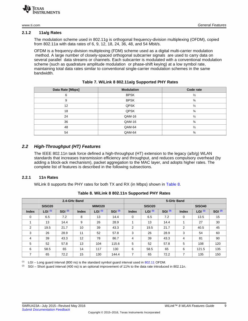
2.2.1 11n RatesWiLink 8 supports the PHY rates for both TX and RX (in Mbps) shown in Table 8.
(1) LGI – Long guard interval (800 ns) is the standard symbol guard interval used in 802.11 OFDM.(2) SGI – Short guard interval (400 ns) is an optional improvement of 11% to the data rate introduced in 802.11n.
Table 8. WiLink 8 802.11n Supported PHY Rates
2.4-GHz Band 5-GHz BandSISO20 MIMO20 SISO20 SISO40
Index LGI (1) SGI (2) Index LGI (1) SGI (2) Index LGI (1) SGI (2) Index LGI (1) SGI (2)
0 6.5 7.2 8 13 14.4 0 6.5 7.2 0 13.5 151 13 14.4 9 26 28.9 1 13 14.4 1 27 302 19.5 21.7 10 39 43.3 2 19.5 21.7 2 40.5 453 26 28.9 11 52 57.8 3 26 28.9 3 54 604 39 43.3 12 78 86.7 4 39 43.3 4 81 905 52 57.8 13 104 115.6 5 52 57.8 5 108 1206 58.5 65 14 117 130 6 58.5 65 6 121.5 1357 65 72.2 15 130 144.4 7 65 72.2 7 135 150

General Features www.ti.com
10 SWRU423A–July 2015–Revised May 2016Submit Documentation Feedback
Copyright © 2015–2016, Texas Instruments Incorporated
WiLink™ 8 WLAN Features Guide
2.2.2 MIMO at 2.4 GHzThe use of multiple antennas and the antenna-based multiple input, multiple output (MIMO) technique is akey feature of 802.11n equipment that sets itself apart from the earlier 802.11a/g equipment. This usage isresponsible for superior performance, reliability, and range.
MIMO systems (WiLink8.0 supports 2x2 MIMO) divide a data stream into multiple unique streams, each ofwhich is simultaneously modulated and transmitted through a different radio-antenna chain in the samefrequency channel. MIMO leverages environmental structures and takes advantage of multipath signalreflections to improve radio transmission performance.
Through the use of multipath, each MIMO receive antenna-radio chain is a linear combination of themultiple transmitted data streams. The data streams are separated at the receiver using MIMO algorithmsthat rely on the estimates of the channels between each transmitter and receiver. Each multipath routecan then be treated as a separate channel creating multiple "virtual wires" over which to transmit signals.MIMO employs multiple, spatially-separated antennas to take advantage of these "virtual wires" andtransfers more data. In addition to multiplying throughput, range is increased because of an antennadiversity advantage as each receive antenna has a measurement of each transmitted data stream. WithMIMO, the maximum per channel data rate grows linearly with the number of different data streamstransmitted in the same channel.
2.2.3 40-MHz BW OperationWiLink8.0 supports a practical approach of using 40-MHz channels, but in a 5-GHz band. Using 40-MHzchannels or the busy 2.4-GHz band is not advised; use the SISO20 or MIMO20.
Typically, 802.11n allows the configuration of 40-MHz wide channels. Because adjacent channels need aslight gap between them (to separate them in the frequency band), a single 40-MHz channel has slightlymore than twice the bandwidth of two adjacent 20-MHz channels (because the inter-channel frequencygap is now part of the actual channel space). Therefore, a 40-MHz 802.11n channel provides slightlybetter than twice the throughput capacity of a single 20-MHz 802.11n channel. If an 802.11n transmitter isoperating in a 20-MHz channel and can establish a 72.2-Mbps connection, then a 40-MHz channel wouldprovide a 150-Mbps connection; double the channel width to double (plus about 4%) the capacity of theresultant double-wide 802.11n channel.
2.2.4 A-MPDU and A-MSDUThere are two methods available to perform frame aggregation: aggregate MAC protocol service unit (A-MSDU) and aggregate MAC protocol data unit (A-MPDU). The main distinction between MSDU andMPDU is that the former corresponds to the information that is imported to or exported from the upper partof the MAC sublayer from or to the higher layers, respectively, whereas, the later relates to the informationexchanged from or to the PHY by the lower part of the MAC. Aggregate exchange sequences are madepossible with a protocol that acknowledges multiple MPDUs with a single block ACK.
A-MSDU: The principle of the A-MSDU (or MSDU aggregation) is to allow multiple MSDUs to be sent tothe same receiver concatenated in a single MPDU. This improves the efficiency of the MAC layer,specifically when there are many small MSDUs, such as TCP acknowledgments. The main motivations foraggregation at the MSDU layer are:• Ethernet is the native frame format for most clients• Because the Ethernet header is much smaller than the 802.11 header, the multiple Ethernet frames
can be combined to form a single A-MSDU.

www.ti.com General Features
11SWRU423A–July 2015–Revised May 2016Submit Documentation Feedback
Copyright © 2015–2016, Texas Instruments Incorporated
WiLink™ 8 WLAN Features Guide
WiLink8.0 supports A-MPDU for both TX and RX and A-MSDU for RX (see Figure 1).
Figure 1. A-MPDU Aggregation
The decision of using A-MSDU versus A-MPDU is a tradeoff between probability of error andretransmission costs in an A-MSDU, versus MAC frame header overheads in an aggregate with A-MPDU.In most real-world systems, the later wins and most systems implement A-MPDUs.
2.2.5 RIFSReduced interframe space (RIFS) was introduced in IEEE 802.11n to improve its efficiency. RIFS is thetime in microseconds by which the multiple transmissions from a single station are separated. RIFS isused when no SIFS-separated response frames are expected from the receiver. The value of RIFS is 2 μsfor 802.11n phy.
WiLink8.0 supports RIFS in RX (mainly for Wi-Fi certification). For TX (like most other devices), WiLink8.0uses A-MPDU, and chooses not to use RIFS.
2.2.6 BA SessionsBlock acknowledgment (BA) was initially defined in IEEE 802.11e as an optional scheme to improve theMAC efficiency. Recently, ratified amendment 802.11n enhanced this BA mechanism, making support forall 802.11n-capable devices (formally known as high throughput (HT) devices) mandatory.
Instead of transmitting an individual ACK for every MPDU (or frame), multiple MPDUs can beacknowledged together using a single BA frame. Block-Ack (BA) contains a bitmap that accounts thefragment number of the MPDUs to be acknowledged. Each bit of this bitmap represents the status(success or failure) of an MPDU.
Block acknowledgment consists of setup and tear-down phases. In the setup phase, capability informationsuch as buffer size and BA policy are negotiated with the receiver. Once the setup phase completes, thetransmitter can send frames without waiting for an ACK frame. Finally, the BA agreement is torn down witha DELBA frame.
WiLink8.0 supports BA session both for TX and RX.

General Features www.ti.com
12 SWRU423A–July 2015–Revised May 2016Submit Documentation Feedback
Copyright © 2015–2016, Texas Instruments Incorporated
WiLink™ 8 WLAN Features Guide
2.2.7 GreenfieldGreenfield mode is an operational mode of an 802.11n network that can maximizes the speed of datatransfers. The performance boost of the Greenfield mode comes with some significant costs in anyenvironment that includes pre-802.11n client radios.
WiLink8.0 supports all three possible modes: legacy, mixed, and Greenfield modes (see Figure 2).
Figure 2. Legacy, Mixed and Greenfield Preamble Structures
2.3 Quality of Service (QoS)The purpose of WLAN QoS is to allow different types of traffic (voice, video, or normal traffic) to havedifferent priorities when approaching the air (trying to send a frame).
The WiLink8 device supports the enhanced distributed channel access (EDCA) QoS. With EDCA, high-priority traffic has a higher chance of being sent than low-priority traffic. On average, a station with high-priority traffic waits less time before it sends its packet than a station with low-priority traffic.
The levels of priority in EDCA are called access categories (ACs). The contention window (CW) can beset according to the traffic expected in each access category, with a wider window needed for categorieswith heavier traffic. The CWmin and CWmax values are calculated from aCWmin and aCWmax values,respectively, that are defined for each physical layer supported by 802.11e.
EDCA provide four different ACs (from lowest to highest priority):• Background (AC_BK)• Best Effort (AC_BE)• Video (AC_VI)• Voice (AC_VO)
The WiLink8 devices (STA and AP) support the EDCA in both software and hardware: while the softwaremaintains the different AC queues, the hardware runs the “Air Approach” in real-time competition.

www.ti.com General Features
13SWRU423A–July 2015–Revised May 2016Submit Documentation Feedback
Copyright © 2015–2016, Texas Instruments Incorporated
WiLink™ 8 WLAN Features Guide
Table 9 shows the default EDCA parameters.
Table 9. QoS Access Categories
AC CWmin CWmax AIFSN Max TXOPBackground (AC_BK) 15 1023 7 0Best Effort (AC_BE) 15 1023 3 0Video (AC_VI) 7 15 2 3.008 msVoice (AC_VO) 3 7 2 1.504 ms
The actual EDCA parameters are published by the AP side. When running a WiLink8 device as an AProle, you can configure the EDCA parameters in the TI configuration file. There is no option to disableQoS from the STA role (enabled by default), but there is an option in the hostapd.conf file to disable theQoS.
A frame is handled as a QoS frame only if it arrived from the network with QoS information. Each framewithout QoS information is handled as a non-QoS frame. The default parameters of non-QoS frames arethe same as best-effort frames (that is also the case when the AP does not support QoS).
The EDCA QoS is compatible with the Wi-Fi Alliance WMM Certification, with a small modification. WMMdefines eight different TIDs (Traffic ID 0-7), while each traffic ID (TID) gets a specific AC handling.
In a WiLink8 solution, each TID is automatically assigned to its correlated AC (see Table 10).
Table 10. QoS TIDs
TID AC0 AC_BE1 AC_BK2 AC_BK3 AC_BE4 AC_VI5 AC_VI6 AC_VO7 AC_VO
WiLink8.0 devices are fully compliant with Wi-Fi Alliance WMM requirements.
2.4 Protection Types
2.4.1 GeneralThe protection mechanism preserves backwards-compatible interoperability with legacy devices(802.11b/g) from over-the-air collisions as legacy devices cannot detect higher rate energy.
WiLink8 supports all protection methods using the standard mechanisms that are highlighted inSection 2.4.2. For more information, see the 802.11n specification located athttps://en.wikipedia.org/wiki/802.11.
2.4.2 Protection MethodsWhen using 802.11g, RTS/CTS and CTS-to-self frames are used with legacy rates to protect 802.11bstations higher rates transmissions.
When using 802.11n, The AP is responsible for the following Beacon Information Elements:• ERP information element is added when the 802.11b station is part of the BSS and protection is
required.• HT information element contains Operating Mode and Non-Greenfield STAs present fields to determine
whether or not to use protection

General Features www.ti.com
14 SWRU423A–July 2015–Revised May 2016Submit Documentation Feedback
Copyright © 2015–2016, Texas Instruments Incorporated
WiLink™ 8 WLAN Features Guide
Operating Mode has four possible settings:– Mode 0: all stations in the BSS are 20/40-MHz HT capable, or if all stations in the BSS are 20-MHz
HT stations in a 20-MHz BSS– Mode 1: there are non-HT stations or APs using the primary or secondary channels; also called HT
non-member protection mode.– Mode 2: at least one 20-MHz station is associated to the HT BSS.– Mode 3: at least one legacy station is associated to the HT BSS; also called non-HT mixed mode.When using a 20- or 40-MHz HT channel, operating modes 1 or 3, and the Use Protection field is 1 inthe Beacon ERP IE, all HT transmissions must be protected using RTS/CTS or CTS-to-self sent legacyrates. This can occur if there is a 802.11b/g/n device connected to the same AP.
There are two ways to protect the HT transmission:• The device should send RTS/CTS or CTS-to-self prior to the HT transmissions in legacy rates.• The device should use a non-HT/mixed mode preamble, with the first a transmitted PPDU.
The L-SIG value should protect the rest of the transmission. The remaining TXOP following the first PPDUexchange may contain GF or RIFS sequences.
2.5 Suspend and ResumeThe WiLink8.0 chip enters suspend mode when the host decides to enter suspend and sleep mode. In thismode, the WiLink8.0 chip is turned off, allowing for power consumption efficiency. Before enteringsuspend mode, all configurations are saved. Upon resume (usually triggered by pressing the keyboard ortouching the screen), the device is turned on, the wpa_supplicant starts a scan and reconnects to the AP(assuming there is a saved profile).
Unlike Station mode (wpa_supplicant), Suspend/Resume in AP mode requires restarting the hostapdapplication.
There is no resume due to any wireless activity, as the device is turned off.
2.6 WoW (Wake on WLAN)WoW mode refers to the WLAN chip state when the host enters suspend. If WoW is enabled uponsuspend, the WiLink8.0 chip stays turned on, the Station remains connected, and AP keeps transmittingbeacons and preserves the links. In this state, a resume can also be triggered due to WLAN activity.
Use the following to configure the packet types to wake up:1. Enable or disable broadcast frames2. Configure filters on data packets, such as filter by source and destination MAC address, and so forth3. Configure to wake up on the beacon IEs

SoC
control
WLAN 5GHz Tx
WLAN 5GHz Rx
DPDT switch
5GHz antenna port 1
5GHz antenna port 2
www.ti.com General Features
15SWRU423A–July 2015–Revised May 2016Submit Documentation Feedback
Copyright © 2015–2016, Texas Instruments Incorporated
WiLink™ 8 WLAN Features Guide
2.7 Set TX PowerWiLink8.0 has a TX power control mechanism for the STA mode in a 2.4-GHz band. TX power can bereduced in case of a stable link. There are two potential advantages of reducing the TX power:• Reducing current consumption• Reduced interference range. Lower transmission power might interfere less with other devices. This
could lead to increased capacity of the network.
As a general guideline for WiLink8.0 current consumption, it is better to keep high TX power than todecrease the TX rate and the throughput. Thus, TX power control is implemented only for the highestsupported rate per link. The decision to change the TX power level is based on the packet error rate(PER) of the highest supported rate. If PER is low, then power can be reduced, otherwise power is kepthigh.
2.8 5-GHz Antenna DiversityWiLink8.0 supports two-antenna diversity on the 5-GHz band, using an external double pole, double throw(DPDT) switch. This switch can be found on TI MOD1837.
The WiLink8.0 algorithm studies and analyzes the best signal path considering the reasons mentionedearlier, choosing the better of the two paths for transmitting and/or receiving an RF signal to maximize thelikelihood that a packet will be correctly received, and increase throughput. The decision mechanism isbased on RSSI level. 5-GHz antenna diversity is mostly relevant for the following use-cases:• In urban and indoor environments, there is no clear line of sight between the transmitter and receiver.
Instead, the signal is reflected along multiple paths before finally being received. Each of thesebounces can introduce phase shifts, time delays, attenuations, and distortions that can destructivelyinterfere with one another at the aperture of the receiving antenna.
• The antenna radiation pattern defines the variation of the power radiated by an antenna as a functionof the direction away from the antenna. This power variation as a function of the arrival angle isobserved at the antenna far field. Diversity between two antennas with different patterns can overcomenulls.
• Improves performance for Airplay compliance (audio customers)
Figure 3. 5-GHz Antenna Diversity

SoC
2 bit control
BT Tx/Rx
WLAN BG2 Tx/Rx
WLAN BG1 Tx/Rx
RF switch
2.4GHz antenna port
General Features www.ti.com
16 SWRU423A–July 2015–Revised May 2016Submit Documentation Feedback
Copyright © 2015–2016, Texas Instruments Incorporated
WiLink™ 8 WLAN Features Guide
2.9 Wi-Fi – Bluetooth/Bluetooth Smart CoexistenceBoth WLAN and Bluetooth operate on a 2.4-GHz ISM band. Allowing the two technologies to worksimultaneously, especially when located on the same device, is a challenging task that requires specialtreatment to keep performance quality on both sides. The advantage of having both Wi-Fi andBluetooth/Bluetooth Smart on a single combo device such as WiLink8.0 provides better correlationbetween the different IPs to ensure good performance. WiLink8.0 uses a shared antenna for Wi-Fi andBluetooth.
This operation is accomplished by managing a time-division multiplexing (TDM) scheme; transmitting andreceiving independent signals over the shared antenna in an alternating pattern, using an externalcontrolled switch.
The WLAN both switches the antenna to the Bluetooth IP and protects BT traffic from any WLAN traffic byother devices, using a number of different methods.
Figure 4. Wi-Fi – Bluetooth/Bluetooth Smart Coexistence – Shared Antenna
2.10 Wi-Fi – ZigBee CoexistenceWiLink8.0 introduces the Wi-Fi and ZigBee coexistence mechanism when using TI CC2530 for theZigBee. This coexistence is required when placing the WiLink8.0 and CC2530 on the same platform (forexample, ZigBee – Wi-Fi gateway). In that case, the isolation between the antennas of the two devices isnot enough to avoid impact on the performance. Without a proper coexistence mechanism, the RX of theZigBee device will be affected by the Wi-Fi TX and vice versa. The coexistence mechanism protects theZigBee RX using GPIOs interface between the devices. This allows the ZigBee visibility of the Wi-FiTX/RX activity, and also the ability to hold a Wi-Fi transmission.
Figure 5. Wi-Fi – ZigBee Coexistence – GPIOs Interface

www.ti.com General Features
17SWRU423A–July 2015–Revised May 2016Submit Documentation Feedback
Copyright © 2015–2016, Texas Instruments Incorporated
WiLink™ 8 WLAN Features Guide
2.11 Accurate Synchronization Over Wi-FiFor a variety of applications such as audio, industrial, and medical, there is a demand for accuratesynchronization between different Wi-Fi devices (for example, synchronization between left and right audiospeakers). The IEEE802.11 protocol does not allow a high level of synchronization due to its delays,latency, and retries.
WiLink8.0 offers synchronization over Wi-Fi with an accuracy of less than 20 µs.
The WiLink8.0 solution for accurate time synchronization does not require the support of any dedicatedprotocol such as 802.11V.
When used for AP mode, the time synchronization feature works in a way all WL8 connected devices willbe synchronized to the AP time domain. When used for Mesh role, the time is synchronized per zones. itis required to determine in advance which mesh peer is the one that all other mesh peers in its zone needto be synchronized to. The method can synchronize between as many devices as the AP can support.The solution does not require a specific or a proprietary access point.
3 Single Role: Station
3.1 ScanningA transmitted signal is subject to reflections and refraction on walls, surfaces, and so forth. The receivingnode sees signals differing in phase and amplitude. All these signals superposition at the RX antenna,causing an effect called “fading”. Using more than one antenna allows the evaluation of different multipathscenarios to avoid or reduce the effects of fading and interferences.
Scanning is a process Wi-Fi devices use to detect other remote Wi-Fi devices (usually detection of accesspoints before connection). This process can also be used for environment status or other measurements.
There are three primary scan types: Table 11 describes their different purposes and execution. Each scancompletes in a different amount of time, depending on variables such as scan type, configuration, andregulatory rules.
The scan execution in the system is independent and can be executed between other Wi-Fi activities.When a scan is executed in parallel to those activities, it can impact things such as throughput or multi-role (MR) scenarios.
Some typical examples:• Multi-role scenario, where STA and AP roles run traffic to remote devices. Executing a scan impacts
the throughput by up to 80% (during the scan itself) each time a channel is scanned off.• Multi-role scenario where STA is connected and AP is idle. Executing a scan could lower the
connection success rate of a remote STA to less than 100%.
This should be taken into account when frequently executing scans.
The examples in Table 11 describe the shortest, typical, and longest scan process.
Table 11. Scan Types
Scan Band Channels TypeApproximate Duration
[msec]Shortest BG 1-11 Active 500Typical BG 1-11 Active 3000
A 36-161 (No DFS) ActiveLongest BG 1-11 Active 5000
A 36-161 (With DFS) Active + PassiveJ 12-14 Passive

Single Role: Station www.ti.com
18 SWRU423A–July 2015–Revised May 2016Submit Documentation Feedback
Copyright © 2015–2016, Texas Instruments Incorporated
WiLink™ 8 WLAN Features Guide
3.1.1 One-Shot ScanThe one-shot scan is a general name for non-periodic scan types.Application Scan: The application configures all scan parameters, including the channel list and scantype (active or passive).
Table 12. One-Shot Scan
Application ScanParameters
Scan type Passive or activeSSID ANY or specific
BSSID ANY or specific, per channelBand and Channel list Up to 16 channel
Dwell time Min, max per channelEarly termination conditions Per channel
Scan logicFirmware to scan the list of channels
Scan ResultsFirmware filters according to SSID and BSSID parameter
Driver accumulates results during scan processDriver issues scan complete to application
Driver provides API to read the results of scan (accumulated, with aging)
Operation System (OS) Scan: The supplicant configures SSID (usually ANY) and the WLAN driverperforms a one-shot scan on all allowed channels (according to the regulatory domain) in all relevantbands according to the configured SSID.
This scan is typically used for a site survey by the graphical user interface (GUI), using the supplicant’scontrol interface.
Table 13. OS Scan
OS ScanParameters
Scan type Passive or activeSSID ANY or specific
Scan LogicFirmware to scan all allowed channels on all enabled bands
Scan ResultsFirmware filters according to SSID parameter
Driver accumulates results during scan processDriver issues scan complete to application
Driver provides API to read the results of scan (accumulated, with aging)
3.1.2 Connection ScanThis scan is also known as a Scheduled Scan.
The connection scan is a periodic process that scans a list of channels derived from a list of SSIDs, asconfigured by the supplicant. The scan tries to find a matched SSID as part of the connection process.
The traditional approach of the host managing the periodic connection scans is not power efficient,especially when no BSS networks are found and the host is forced to remain awake for the entire durationof the connection scan cycles until an appropriate BSS is found.

www.ti.com Single Role: Station
19SWRU423A–July 2015–Revised May 2016Submit Documentation Feedback
Copyright © 2015–2016, Texas Instruments Incorporated
WiLink™ 8 WLAN Features Guide
To solve this issue, the connection scan is performed and managed from the firmware, minimizing thehost involvement during the scan process, enabling the host to sleep for long periods.
Table 14. Connection Scan
Connect ScanParameters
Scan type Passive, active, or active after passive (DFS), per channelSSID List Inclusion: up to 16 SSIDs (Each SSID is either public or hidden)
SNR, RSSI Filters ThresholdBand and Channel list Up to 41 channels
Dwell time Min, max per channelTermination conditions On report, never or after number of cycles
Periodicity Cycles listScan logic
In case of N (N=0 or more) hidden SSIDs, the firmware transmits, per cycle, per channel, 2*(broadcast_Probe_Request +N*unicast_Probe_Request)
Scan ResultsFirmware filters (optionally) the results according to SSID list and forwards the results that match an SSID
Driver stores the scan results and issues scan report event upon scan resultDriver issues scan complete to application
Driver provides an API to read the results of the scan (accumulated, with aging)
3.1.3 Background ScanThis scan is also known as a Continuous Scan.
The background scan maintains a list of BSS candidates for roaming purposes. Each time a scan isfinished or a roaming trigger is issued, the upper layer checks whether a roaming should be performedand selects the best BSS in the list. The scan period is fully managed by the driver.
For more information, see Section 3.15.
3.2 ConnectionA Wi-Fi connection is a process of establishing a link between two devices for further data exchange. TheWi-Fi connection process usually consists of the following steps:• Scanning• Connection with or without privacy• DHCP exchange
There are two methods to establish connection: manual and automatic. Each method has its own usageand purpose.
3.2.1 Manual (Via Commands)This connection type is established by invoking CLI commands. These CLI commands define a networkindex, security type, SSID name, unicast scanning, and more.
More than one network might be defined, but only one will be enabled and selected for the connection.Switch between the pre-defined profiles by selecting the known index.
The lifetime of these defined networks lasts until the next driver or platform restart. After the restart, nonetwork profile will exist.
This connection process is typical for systems with no upper application layer that can remember andstore all successful connections and record those as useful profile or preferred network (seeSection 3.2.2).

Single Role: Station www.ti.com
20 SWRU423A–July 2015–Revised May 2016Submit Documentation Feedback
Copyright © 2015–2016, Texas Instruments Incorporated
WiLink™ 8 WLAN Features Guide
Typically, this connection type requires a scanning operation to detect the neighbor APs, routers, orhotspots to discover a required network for connection. However, the connection is also established as astandalone action even if the scanning was not invoked. This is because the connection process itself hasits own inherent scanning (scheduled scan) that scans all channels and connects to the required networkif it exists, or continues to scan periodically until it sees the disconnect command or the role stop.
3.2.1.1 Connection TimeThe connection time may vary between 50 msec to a few seconds. This variance is because theconnection process consists of a few independent processes, listed above, that have a duration that mayvary according to the configuration or network topology.
On top of the inherent components of the connection process, there are few environmental and systemreasons that impact the connection time, and cannot be expected or controlled.
The following three examples describe the shortest, typical, and longest connection process:• Shortest connection process:
– No security usage, neither personal nor enterprise– Highest RF modulation (PHY rate) usage– No DHCP process for acquiring an IP address, but a usage of a pre-defined IP address– Operation in a clean environment without any interference, such as WLAN, BT, and other
A usage of the above configuration is not recommended for the following reasons:• The unsecured connection with unencrypted data may result in the system getting hacked, in
terms of stealing data or other damage to the network.• The highest modulation usage during the connection process may lead to a less robust
connection, depending on the RF conditions.• The static IP address usage may lead to an IP address conflict in the system, and block the
device from data exchange.• Longest connection process:
– An Enterprise authentication process with certificates exchange– Lowest RF modulation (PHY rate) usage– Acquiring an IP address from a DHCP server located after a few routers within some enterprise
network– Operation in a noisy environment, leading to a packet retransmission or to the whole process
repetition, if some packet is lost within the BT operation sharing the same antenna and operatingon a time-division basis. The antenna will be taken from the WLAN and packets might be lost.In the above scenario, if the complete connection process must be repeated, it could take 3 to 5seconds or more.
• Typical connection process:– Non-enterprise environment, such as home, car, or other private networks– Moderate RF modulation– IP address acquisition from a local DHCP server (such as a router or a hotspot)
In this connection scenario, the typical connection time is 0.5 seconds, which consists of:• 50-msec WLAN open connection• 100-msec 4-way handshake for a private and a group key generation• 300 msec for the IP acquisition using the DHCP process
3.2.1.2 Connection Success RateThe connection success rate, or the number of successful connections out of the connection trials, is ameasure of system robustness and can indicate a system's ability to establish a WLAN connection onceinvoked.
The expected rate of successful connections is 100% of the connection trials; however, it might be lowerdue to environmental and system reasons. Often, those reasons cannot be controlled or expected.
www.ti.com Single Role: Station
21SWRU423A–July 2015–Revised May 2016Submit Documentation Feedback
Copyright © 2015–2016, Texas Instruments Incorporated
WiLink™ 8 WLAN Features Guide
3.2.1.3 Connect to Best BSSID of the Configured SSIDIn environments where few APs with the same SSID exist, such as an enterprise network or homenetwork that might have a router and repeater, the station may detect more than one AP. In this case, thestation selects an AP with a higher RSSI. The current AP's profile is temporarily stored and used by thestation for connection to any AP with the same SSID, in case of a disconnect from the original AP.
3.2.2 Automatic (Via Profiles)Section 3.8 describes using the profiles in detail. Once one or more profiles are defined in the supplicantresponsible for the connection process, the device starts a process toward the connection. If an AP withparameters suitable to one of defined profiles is detected, a connection is invoked.
3.2.3 Wi-Fi Protected Setup (WPS)The WPS method is an additional way to establish a Wi-Fi connection. The WPS-capable devices declarethis capability in the beacons and probes. In this method, the connection is secured and the dataexchange encrypted. The WPS connection method is invoked in two ways: hardware and software. Boththe hardware and the software processes are invoked using one of two WPS connection methods: PBC orPIN. When one device has started a WPS connection process, the second device has two minutes torespond to the connection initiator device. After two minutes, the connection initiator stops the process.
An advantage in either WPS method is that the secured Wi-Fi network can be joined without knowing theprivacy key.
A disadvantage is that during the WPS connection process, no specific SSID is defined. This limitation canresult in a situation where two independent stations start a WPS process concurrently, for example, withinthe two minute time frame, and the peer station will not know which of them to connect to. This situation iscalled WPS overlapping. The peer station is only able to connect when one station terminates the WPSconnection process.
3.2.3.1 WPS PBCThe WPS push-button connection method is invoked by pushing a button on a device (the hardwaremethod), or by running a dedicated command or selecting an option from a menu (the software method).In the Linux OS, the CLI command is used, and in the Android OS, the WPS connection is invoked byselecting the WPS option in the menu. In both cases, the result will be the same; after a WPS-securednegotiation process, a connection is established.
3.2.3.2 WPS PINA PIN method is another option for establishing the WPS connection. In this case, one Wi-Fi device has apre-defined PIN key printed on the label, usually 8 digits in length, while the other Wi-Fi device inserts thiskey after starting the WPS connection process. The side with the pre-defined key is called Label and thedevice inserting the key is called Keypad. Both relate to the PIN method. After inserting the key, theconnection process is the same as with the PBC method. An alternate method to the Label option is aDisplay method. Usually, this case is used when the connection is established by commands, such as inLinux OS, or from menu, such as in the Android OS.
3.3 DisconnectionDisconnection stops the connection between an AP and an STA.
It could occur for various reasons:• In case of low RSSI, when the STA leaves the range and the signal is low, the STA cannot transmit or
receive data clearly, and disconnects.• AP or router turn-off• AP changes parameters such as SSID or authentication type• Wrong security parameters or password• Exceeded number of unacknowledged packets

Single Role: Station www.ti.com
22 SWRU423A–July 2015–Revised May 2016Submit Documentation Feedback
Copyright © 2015–2016, Texas Instruments Incorporated
WiLink™ 8 WLAN Features Guide
After the disconnection process, if the STA has any saved profiles, it starts to scan. If any candidate isdiscovered, it connects.
3.4 DHCP ClientAn IP address must be received for a network client (such as a station) to establish a connection with datatransfer to any WLAN network.
Unlike static IP configuration, where there is a set IP address, DHCP is a dynamic protocol that allows anexternal server to lease IP configurations based on a defined pool of addresses. A DHCP process occurswith every new connection, and an address is given to the station.
The advantage of DHCP over static IP is that addresses are not wasted and do not conflict with otherdevices in the same network.
3.5 SecurityWireless encryption and authentication only allow devices with the corresponding authentication andencryption types to be connected. To connect a wireless device to a certain router, the device alsorequires the correct key (password).
3.5.1 Authentication TypesWiLink8 STA mode supports the following three authentication types: open, personal and enterprise.
The first is open, where it allows to authenticate only with open authentication AP.
The second is personal authentication, where the password is configured to the AP and the AP itselfauthenticates the peer device using a password.• Wi-Fi Protected Access (WPA)• Wi-Fi Protected Access v2 (WPAv2)
The third is enterprise authentication, where a Radius server behind the AP authenticates the peer device.• EAP• EAP-TLS• EAP-TTLS• PEAPv0• PEAPv1
3.5.2 Encryption TypesEach encryption type can be used with either authentication type.• Open (no encryption)• WEP (wireless equivalent protocol)• TKIP (temporal key integrity protocol)• AES (advanced encryption standard)
3.5.3 Broadcast Key Rotation (BKR)Broadcast key rotation (also known as group key update) allows the access point to generate the bestpossible random group key, and update all key-management capable clients periodically.
3.6 Filtering
3.6.1 Beacon FilteringWLAN beacons are identical from one beacon to the other, in most cases, other than the timestamp (TSF)and the Traffic Indication Map (TIM) information.

www.ti.com Single Role: Station
23SWRU423A–July 2015–Revised May 2016Submit Documentation Feedback
Copyright © 2015–2016, Texas Instruments Incorporated
WiLink™ 8 WLAN Features Guide
The TSF and the TIM are handled by the firmware (for real-time purposes). The WiLink8 driver (andsupplicant) always receives one (first) beacon; the others are configurable. The host can configure to thefirmware which IEs are relevant and the firmware sends the driver only beacons with the configured IEs.
The host can configure for each relevant IE whether the Transfer, when there is a change in the IE'scontent, or Relevant IE appears in the beacon. For the latter, the firmware saves the last beacon in its DB,and compares the new beacon with the beacon from the DB. If there is a match, the entire beacon will besent to the host. Each IE that is not configured is handled as non-relevant and ignored.
Configure the IEs with TI wlconf file as shown in Table 15.
Table 15. Beacon Filtering Parameters
Parameter Informationcore.conn.bcn_filt_mode Beacon Filter Enable and Disable
core.conn.bcn_filt_ie_count Number of relevant IE’s in the table (up to 32)core.conn.bcn_filt_ieXXX.ie IE Id
core.conn.bcn_filt_ieXXX.rule Action to be done0 – Ignore
1 – Relevant IE (Check for Change)2 – Transfer (if IE Exist send to host)
core.conn.bcn_filt_ieXXX.oui & type Additional IE Information for Vendor Specific (221) IE
3.6.2 Multicast FilteringMulticast filtering is done in the firmware level. On initialization, the multicast filter is disabled and allmulticast frames are sent to the host. To get only specific multicast frames, register to specific multicastgroups; only those groups will be filtered in, while all other multicast frames are dropped. The WiLink8software supports up to eight different multicast groups that can be configured. The multicast filter shouldonly work for the STA role, as the AP role should distribute all multicast frames to all other devices.
3.7 Auto ARPAddress resolution protocol (ARP) translates IP addresses into MAC addresses and saves them in theARP table. Because network communication is done through MAC addresses, ARP is needed toassociate the specific IP address to its specific MAC address.
When any packet is sent and the destination IP address does not exist in the ARP table, an ARP requestpacket is sent in broadcast to link the IP address and MAC address together. The relevant party of the IPaddress answers with an ARP reply (not in broadcast).
Auto ARP is a mechanism that filters the ARP request packets sent in the network. These ARP requestpackets are filtered from the Host in order to reduce the power consumption (The Host does not need towake up to send the reply).
When a packet is detected with an irrelevant IP address (not the station), the station drops the packet.This is done by the firmware, and is not seen in the driver. When a packet is detected with a relevant IPaddress, the firmware answers with an ARP reply, and no messages is seen on the driver level.
3.8 Preferred Networks (Profiles)Preferred networks or profiles refer to Wi-Fi networks that you have explicitly pre-defined or that havebeen learned and stored by WLAN-capable devices. A preferred network definition consists of a Wi-Finetwork name, security definition, hidden/non-hidden network, and a priority of network.
These networks are written in the WLAN supplicant configuration file and used for automatic connectiononce one or more of them have been discovered during a scan phase initiated by an application thatintends to invoke connection. The decision to start a connection scan varies between operating systemsand applications that manage connection. Typically, once Wi-Fi is enabled on the device, and one or moreprofiles are defined, the scanning starts.

Single Role: Station www.ti.com
24 SWRU423A–July 2015–Revised May 2016Submit Documentation Feedback
Copyright © 2015–2016, Texas Instruments Incorporated
WiLink™ 8 WLAN Features Guide
After getting a scan result, the device checks one or more networks that are suitable to one of storedprofiles that were detected. In case of suitability, the device will invoke a connection to this device. Thesuitability is expressed in the same network name and security type. However, in case of a network withsecurity, if the profile's security type is correct - but the security key is wrong, the connection process willstart - but a complete connection will fail. After the scan cycle, if there is more than one match with thestored profiles’ list, the user that manages the connection process will prefer the Wi-Fi network with thehigher RSSI. However, the selection depends on the user preferring to connect to the network with ahigher priority, actually, meaning to the last connected network.
3.8.1 Hidden NetworkA Wi-Fi network might be defined so that it is invisible to Wi-Fi stations. A network's invisibility isexpressed by not advertising the network name in beacons and ignoring the received probe requests fromthe Wi-Fi station. Such networks are called hidden networks. Their purpose is to avoid seeing orconnecting to undesirable Wi-Fi stations.
Practically, the only way to see or connect to a hidden network is with an explicit manual definition of aprofile suitable to this network. The exact name of the network and its security type must be known; theprofile's creation to this network will not be enough to permit connection to it. Such a profile must bedefined as a hidden network profile. The profile causes the connection manager to invoke a unicast scan,which will look explicitly for a network with this name to broadcast a scan. When the hidden networkreceives a scan request carrying its network name and responds to it, the scanning station is aware thatthis network is available for connection.
The number of the unicast probe requests transmitted during each scan interval is derived from thenumber of hidden networks that are defined.
3.9 Power-Save ModeAs long as the WLAN on the chip works, power is consumed. When working without a constantconnection to electricity, it is important to reduce the current consumption of the device. However, to savepower and maintain acceptable performance, there must be a power-saving mechanism.
When the STA enters power-save mode, the WLAN on the chip goes into sleep mode (extreme low-power(ELP) mode), drastically decreasing power usage.
3.9.1 ActiveIn this mode, the WLAN on the chip always stays awake, even if there is no activity such as traffic, scans,and so forth. This mode is not efficient for power consumption; however, it achieves the bestperformance.
3.9.2 Auto Power-Save ModeIn this mode, the STA automatically switches between active and power-save mode.
When the STA is connected in idle mode and has no need to send or transmit any data, the STA is inpower-save mode. However, if the STA must perform any activity in the network, such as receiving traffic,it sends a null data frame with the power save bit off. Thus, the STA is in active mode from that point untilthe activity has been finished. After a pre-configured amount of time, the null data frame with the powersave bit on is sent to the access point, and the STA returns to power-save mode.
This ensures a balance between power consumption and best performance.
3.9.3 Forced Power-Save ModeIn this mode, the STA remains in sleep mode most of the time, even during intervals of receiving traffic.
The AP buffers the data destined to the STA in forced power-save mode and publicizes in its beacon thatit has data for the specific associated station. The STA is awakened by the predefined interval anddetected in the beacon of the AP if there is any data for the station in the AP’s buffer.

www.ti.com Single Role: Station
25SWRU423A–July 2015–Revised May 2016Submit Documentation Feedback
Copyright © 2015–2016, Texas Instruments Incorporated
WiLink™ 8 WLAN Features Guide
When saved data is in the buffer, the STA sends a trigger packet that pulls the data from the AP. In thedata packets, the AP enables the bit that indicates “more data”, which lets the STA know it should stayawake for more packets until it receives a frame from the access point indicating “no more data”. TheSTA then returns to sleep and this cycle repeats itself.
3.10 Power-Save Delivery ProtocolsThere are two kinds of power-save delivery mechanisms when STA is configured to power save: legacypower save and UPSD.
3.10.1 LegacyIn this mode, when the STA detects that the AP has data for it in the beacon frame, it sends a triggerpacket named PS-POLL to the AP. In response, the AP sends the first queued frame to the STA; if theMore Data field in this frame is on, it sends another PS-POLL frame to the AP. The STA continues to sendPS-POLL frames to receive all the queued frames, until there are no data packets left. After this, thestation returns to sleep until the next listening interval.
This method is suitable for very low data usage, as it is not efficient enough to pull each single packet.
3.10.2 U-APSDThe unscheduled automatic power-save delivery (U-APSD) mechanism is also known as wireless multi-media (WMM) power-save. Legacy power-save methods can decrease the quality of periodic bi-directionaltraffic consisting of short frames as in VoIP. Because VOIP data should send data periodically on a fixedtime (20 msec. for VOIP call), the legacy mechanism is not efficient enough. The U-APSD mechanismwas built to optimize the legacy mechanism.
U-APSD is basically a polling scheme, similar to the legacy power-save delivery. However, in U-APSDmode, any transmitted frame, while in power-save mode, acts as a polling frame and triggers the AP torelease a buffered frame from the same access category (AC) as the transmitted packet (the number offrames that are released by the AP is configurable and determined during the connection phase). Forexample, a voice packet releases only voice-buffered packets. If there are no transmitted packs, STAsends QoS null data packets (after the AP publicizes in its beacon that it has data for the specificassociated station), which polls the buffered data. This is very efficient for bi-directional traffic streams,such as VOIP call.
As the STA awakes from power save to transmit the data, the STA then takes advantage of it to get anydata buffered from the AP. This feature only works if the STA and AP are configured to WMM-enabled.
3.11 Keep-Alive MechanismIn a network client (station), messages are sent to the current connected access point to keep theconnection during periods of idle activity. These messages are called Keep-Alive. Keep-Alive messagesare generated independently by the WLAN device (station) according to the host configuration, allowingthe host to optimize the length of its low power-time interval. The Keep-Alive messages are not sent fromthe Host, thus, the mechanism improves the power consumption. Also, the frequency of messages have adirect effect on power consumption; therefore, the longer the interval between Keep-Alive messages, themore efficient in power consumption.
3.12 Smart ConfigThe Smart Config is a method to allow the WLAN device to be connected to the network without having toconfigure the AP information on the device. This method is required for devices without a GUI orkeyboard. The main target of the procedure is to receive (over the air) the SSID and password of the APthat the device should connect to, from a third-party device. Once the device gets these parameters, itconnects to the AP and obtains an IP address.
Use a third-party device to deliver the network parameters (SSID + password). Enter the WLAN deviceinto Smart Config mode by either pressing a button or simply turning on the device; the device then movesto Sniff mode.
Single Role: Station www.ti.com
26 SWRU423A–July 2015–Revised May 2016Submit Documentation Feedback
Copyright © 2015–2016, Texas Instruments Incorporated
WiLink™ 8 WLAN Features Guide
The third-party device periodically transmits a SYNC pattern interlaced with the encoded SSID + passwordof the AP. The WLAN device scans all channels, searching for the SYNC pattern. Once the WLAN devicefinds the SYNC pattern, it tunes to the specific channel the pattern was found on, and starts receiving theSSID + password. Once done, the device exits Smart Config mode and connects to the requestednetwork with the SSID + password.
3.13 Regulatory DomainThe regulatory domain feature implements the IEEE 802.11d specification. Each country has a differentlist of channels in which it is allowed to operate. The AP is responsible to publish the country IE in itsbeacons. This IE contains all the information regarding the country being operated in, the allowedchannels and allowed TX power on each channel. The STA must parse the country IE it receives (fromany beacon, even before a connection is established), and act according to its content. There areseparate IEs for 2.4-GHz and 5-GHz bands. The information from the country IE affects the way the STAperforms a scan on each channel (passive/active), and the TX power used on each channel.
3.14 DFS Slave (Channel Switch)The dynamic frequency selection (DFS) channels are 5-GHz channels, 52 to 140, where radar canoperate. Channel switch is a mechanism implemented to avoid co-channel operation with radar systems.This feature verifies that the STA does not transmit any packets in DFS channels upon radar detection.
The AP is the master and must detect the radar and notify the client-slave that should get the info from theAP. The AP informs associated STAs that the AP is moving to a new channel and maintains theassociation by advertising the switch using channel switch announcement elements (IE#37) in beaconframes, probe response frames, and channel switch announcement frames, until the intended channelswitch time. The AP may force STAs in the BSS to stop transmissions until the channel switch takesplace, by setting the channel switch mode field in the channel switch announcement element to 1.
The channel switch should be scheduled so that all STAs in the BSS, including STAs in power-savemode, have the opportunity to receive at least one channel switch announcement element before theswitch. An STA that receives a channel switch announcement element can choose not to perform thespecified switch and take alternative action instead. For example, it can choose to move to a differentBSS. An STA in a BSS that is not the AP must not transmit the channel switch announcement element.
3.15 RoamingRoaming is a process of stations (SUT) switching from one BSS (AP) to another BSS within ESS (APswith the same SSID within LAN). This behavior is used inside enterprise Wi-Fi networks to permit acontinuous and smooth usage of the network when moving within ESS boundaries. An enterprise networkcan be an office, campus, airport, or any other environment that has more than one AP with the sameSSID, and connected to the common backbone. The roaming process should be seamless and as easy aspossible within the capabilities and limitations of the mechanism.
3.15.1 Roaming MechanismThe roaming mechanism operates in station and connected states only. The mechanism might be enabledonly at the connection point. After connection, the process cannot be enabled or disabled.
The roaming process consists of a few segments:1. Enabled mechanism (at the connection point)2. Continuous searching for potential roaming candidates using a background scan3. Decision to roam4. Disconnect from the current connected AP5. Connect to the candidate AP
3.15.1.1 Mechanism EnablingThe roaming mechanism might be enabled only at the connection point. The enabling of the mechanism isdone by defining parameters for the scan and a critical RSSI level.

www.ti.com Single Role: Station
27SWRU423A–July 2015–Revised May 2016Submit Documentation Feedback
Copyright © 2015–2016, Texas Instruments Incorporated
WiLink™ 8 WLAN Features Guide
3.15.1.2 Roaming Candidates ListWhen a station is connected and the roaming mechanism is enabled, it starts to scan periodically; thisprocess is called a background scan. The scanning interval is defined during connection, and depends ona customer's needs. The characteristic value is 10 seconds. During each scan instance, the station onlyscans one channel. The purposes of the scan are to detect APs with SSID, like the currently connectedSSID of the AP, and to reveal its RSSI. Once an AP with the same SSID is detected, its channel isscanned during each scan period, in addition to the regular one-by-one channel scan to get the updatedRSSI level information. The scan may be active, using probe requests and receiving probe responses, orpassive, by listening to AP beacons, depending on driver configuration and other aspects. All channels arescanned according to a regulatory domain configuration.
If the RSSI level of the current connected AP decreases below the defined RSSI level threshold, thestation invokes a one-time scan instance on all channels within one scan interval. The purpose is to detecta roaming candidate AP with a higher RSSI level, to avoid a performance degradation and a potentialdisconnect. Then, it continues the one-by-one channel scanning.
3.15.1.3 A Decision to RoamWhen a suitable AP is detected (with the same SSID), its RSSI level is compared with the RSSI level ofthe currently connected AP. This comparison is done at any RSSI level of the currently connected AP andregardless of the defined RSSI level threshold explained above.
Another reason to roam is if the currently connected AP disappears. In this situation, if a suitable AP wasdetected beforehand, the station connects to it; otherwise, it invokes a scan to detect it. If no AP isdetected, the station disconnects and starts a periodic connect scan.
3.15.1.4 Connection to a Better APOnce the station has decided to roam, due to one of the aforementioned reasons, it disconnects from thecurrently connected AP, then connects to the candidate AP. The roaming process time varies between150 ms and 800 ms, depending on security type, environmental congestion, and so forth. Table 16 showsan example of roaming process time in a clean environment.
Table 16. Estimated Roaming Timing
Security Estimated Roaming Time [msec]Open 150
WPA2-PSK 200WAP2-TLS (Enterprise) 200
3.15.2 Roaming TriggersRoaming has two main triggers: low RSSI level and loss of AP beacons.
3.15.2.1 RSSI Level DeltaAfter detecting an AP with the same SSID, the RSSI level is compared to the RSSI level of the currentlyconnected AP. If the RSSI level of the detected AP is higher, the station will roam. This trigger is calledLow RSSI. The delta in the RSSI levels, between the currently connected AP and the candidate AP, variesaccording to the RSSI level of the currently connected AP, with a variation between 1 to 5 dB.
3.15.2.2 APs DisappearingThe currently connected AP may disappear for different reasons, such as power interruption, unexpectedobstacles, or a very high interference. The disappearance is measured by a number of continuous, absentbeacons from the currently connected AP. If it crosses a defined threshold, the roaming is invoked. Thistrigger is called BSS Loss.

Single Role: AP www.ti.com
28 SWRU423A–July 2015–Revised May 2016Submit Documentation Feedback
Copyright © 2015–2016, Texas Instruments Incorporated
WiLink™ 8 WLAN Features Guide
4 Single Role: AP
4.1 ConnectionThe access point constantly transmits broadcast beacons with relevant information according to definedconfigurations (security, SSID, PS, RSSI, SISO/MIMO, supported rates, regulatory domain IE, and WMM),which allows other stations to know of its existence and capabilities. Once an external station detects thebeacons, the connection process can start.
The authentication process proceeds as follows:1. Station sends an Auth packet to the AP.2. AP replies with an Auth packet.3. Station sends an Association Request packet that matches the capabilities of the AP.4. AP accepts the connection, it sends an Association Response packet with a successful state.
If the AP is configured with security, the AP verifies the connection with keys.1. AP sends an EAPOL-Key packet.2. Station replies with an EAPOL-Key packet.3. AP sends a third EAPOL-Key packet.4. Station sends the fourth EAPOL-Key packet.5. Connection is then established successfully.6. If the key is incorrect, after a few EAPOLS from the AP, the AP sends a deauthentication packet.
At the end of the connection process, an IP is required. If the STA requests an IP address, the AP willprovide it.
The AP also supports a connection using Wi-Fi protected setup (WPS), as described for the STA role.
4.2 Hidden SSIDHidden SSID is one method to provide wireless security by hiding the network name. When hidden SSIDis used, the network ID (SSID) is not broadcasted in the AP beacons.
The AP does not reply with a probe response to any device, other than from a probe request with thespecific SSID. This method is not secured, as it is possible to see the SSID of the specific AP from theprobe request, using the sniffer. When scanning the air with a wireless device, the AP with the hiddenSSID will not be found.
A connection scan must be performed for a wireless device to connect, which means transmitting aunicast probe request with the SSID.
4.3 SecurityWireless encryption and authentication only allow stations with the correct key to connect to the wirelessrouter. The better the wireless encryption and authentication, the more difficult it is to connect and todecrypt the data. When assigning a wireless router with a key, and assigning an encryption method, onlyan STA with the same key can connect and decrypt the data. This prevents other stations from connectingand accessing the data. Wireless routers support multiple wireless encryption and authentication methods.
As mentioned in Section 3, there are three main authentication categories: open, personal and enterprise.The WiLink8.0 AP mode only supports open and personal authentication, where the password (if required)is configured to the AP, and the AP itself authenticates the peer device using a password.• WPA (Wi-Fi protected access)• WPAv2 (Wi-Fi protected access v2)
AP mode also supports the below encryption types:• Open (no encryption)• WEP (wireless equivalent protocol)• TKIP (temporal key integrity protocol)
www.ti.com Single Role: AP
29SWRU423A–July 2015–Revised May 2016Submit Documentation Feedback
Copyright © 2015–2016, Texas Instruments Incorporated
WiLink™ 8 WLAN Features Guide
• AES (advanced encryption standard)
AP mode also supports broadcast key rotation, which allows the access point to generate the bestpossible random group key and periodically update all key-management capable clients.
4.4 Regulatory DomainThe regulatory domain feature implements the IEEE 802.11d specification.
Each country has a different list of channels in which it is allowed to operate. The AP is responsible forpublishing its beacons using the countries IE. This IE contains all the information regarding the countrybeing operated in, and the allowed channels and allowed TX power on each channel.
The AP takes this information from the CRDA file, which contains updated information on all allowedchannels and TX power in each country.
The country can be configured in the AP configuration file according to the configured country; the APreads the relevant information from the file and publishes it in its beacons.
4.5 AP ScanThe AP can detect other networks in parallel to its own operation. This scan is performed similarly to howthe STA executes a scan. The most common use for an AP scan is when the AP is started on a 40-MHzchannel, and it is required to find a suitable channel on the 5-GHz band.
4.6 Automatic Channel Selection (ACS)Automatic channel selection (ACS) helps the AP choose the optimal channel for its operation. Thechannel is chosen by scanning all channels on the configured band (survey), and filtering out channelswith the highest number of other APs. The mechanism tries to choose the channel with the least numberof APs, also taking into account the regulatory domain rules and other user-defined constraints.
4.6.1 40-MHz OperationThe mechanism uses the number of APs on a channel as a crude measure for the noise on that channel.If 40-MHz operation is required, the ACS algorithm tries to choose an appropriate secondary channel(above or below) by going over all of the channel pairs where the primary channel has a minimum numberof APs. If such a pair is found that satisfies all constraints, 40-MHz operation is enabled. Otherwise, theAP is enabled with 20-MHz operation.
A further optimization has been added to choose the best 40-MHz secondary channel.
When choosing a channel, scan all available secondary channels to choose one with the minimumamount of APs.
4.6.2 ACS Whitelist and Blacklist ChannelsThe user can limit the channels used by ACS. The solution supports both a whitelist and a blacklist ofchannels. To use the channel blacklist, define a list of channels that will never be chosen when ACSselects a channel. To use the channel whitelist, define a list of channels that will be chosen only amongthose whitelisted.
Both whitelist and blacklist can be used simultaneously.
4.7 Maximum Connected StationsThe soft AP is capable of supporting up to a total of 10 connected STAs. The number of connected STAsthat are supported does not change when running multi-role with two soft APs (both of which support up toa total of 10 STAs). The soft AP is capable of running equal traffic to all connected STAs. The AP alsomaintains a Block-Ack session and aging mechanism for each link.

Single Role: AP www.ti.com
30 SWRU423A–July 2015–Revised May 2016Submit Documentation Feedback
Copyright © 2015–2016, Texas Instruments Incorporated
WiLink™ 8 WLAN Features Guide
4.8 AgingThe purpose of the aging mechanism is to deauthenticate an associated STA that is no longer connected,to save AP resources. Aging mechanisms usually come into play when there is a sudden network loss ofan external connected station, thus, the mechanism frees up allocated space. It has default configurations,but can also be altered according to need.
4.9 DFS MasterWorldwide, most of the 5-GHz band frequencies are used by radar systems. The same frequency bands(or subsets) were allocated to unlicensed WLAN devices. A requirement arising from this frequency bandreuse is a method called dynamic frequency selection (DFS). A system that requires DFS must becapable of avoiding interference with radar systems, according to the regulatory requirements asdescribed in each DFS standard.
4.9.1 DFS StandardsThere are stringent government regulatory requirements that must be followed by Wi-Fi radios whenoperating on 5-GHz band frequencies. The regulatory bodies specifying and enforcing these requirementsare:• Federal Communications Commission (FCC) in North America• European Telecommunications Standards Institutes (ETSI) in the European Union• TELEC in Japan
The differences between these DFS standards are primarily in the methods to detect radars operating in achannel that satisfy regulatory requirements. Each one defines different types of radio parameters such aspulse width, PRF, modulation, and so forth, and measures the detection success rate.
Most tests regarding the DFS master way of operation, once radar is detected, are similar and focus onthe DFS timing requirements. These tests verify the timing on the parameters as summarized in Table 17.
Table 17. DFS Time Requirements
Parameter RequirementChannel Availability Check Time 60s (some have 10 minutes)
Channel Move Time 10s (maximum)Channel Closing Time 260 ms (maximum)Non-occupancy period 30 minutes (minimum)
4.9.2 DFS MechanismOn detection, the AP must notify all connected stations and move to a different frequency. This is doneusing channel switch announcement elements (IE#37) in beacon frames, probe response frames, andchannel switch announcement frames, until the intended channel switch time. This capability is known asdynamic frequency selection or DFS master. DFS master capabilities allow a device to properly utilize the5-GHz band in an AP role. A Wi-Fi device without DFS master capabilities is permitted to operate as anAP, but only in a small subset of the 5-GHz band, and in certain countries it is limited to indoorapplications only.
Radar detection must be done in two scenarios:• Channel Availability Check (CAC): When moving to a new channel, the DFS master must first
withhold any transmission for a period of 1 or 10 minutes (depending on the channel and the regulatorydomain). During this period, it tests the channel for radar signaling presence, and approves ordisapproves the channel.
• In-Service Monitoring: During any activity in a certain channel, the DFS master must identify anyradar signaling in the operating channel. Upon radar detection, the master device instructs allassociated slave devices to stop transmitting on this channel, which they do within the channel movetime, then switch to a different channel.
www.ti.com Single Role: AP
31SWRU423A–July 2015–Revised May 2016Submit Documentation Feedback
Copyright © 2015–2016, Texas Instruments Incorporated
WiLink™ 8 WLAN Features Guide
After radar detection on a certain channel (during CAC or in-service monitoring), the channel is disabledfor any transmission for a predefined period of time. This period is referred to as the non-occupancyperiod (usually 30 minutes). The device keeps a list of disabled channels and enables each channel whenits individual non-occupancy period has expired.
4.9.3 WiLink8.0 DFS Master CapabilitiesWiLink8.0 possesses DFS master capabilities in all three regulatory domains: TELEC, FCC, and ETSI.The active domain is configured according to the Region parameter.
4.10 Access Control
4.10.1 BlacklistBlacklist refers to a list of MAC addresses from which connection will not be established. Use a blacklist todeny access to a particular and defined MAC address for WLAN connection.
All MAC addresses that are predefined and placed in that specific folder cannot be accessed, and theconnection will not succeed. This can be used in addition to other security measures.
4.10.2 WhitelistWhitelist refers to a list of MAC addresses from which connection or acknowledgment is permitted. Use awhitelist to allow only particular and defined MAC addresses for WLAN connection.
All MAC addresses that are defined and placed in a specific folder can be accessed; connection will notbe established to MAC addresses that are not specified. This can be used in addition to other securitymeasures.
4.11 Extreme Low Power (ELP)Unlike a conventional AP, portable devices implementing the software AP feature cannot be assumed tobe tethered to a power supply, and the role of a soft AP is much more demanding than the role of a legacySTA. Therefore, there is an inherent requirement to reduce the power consumption of the device whileserving the role of soft AP, without any significant performance impact. This requires a standalone powersave mechanism at the soft AP that reduces the power consumption of this device without any explicitmessages to the STAs.
WiLink8 supports low-power consumption AP mode when running idle (no STAs are connected). In thismode, the AP still has a high discoverability rate.
5 Single Role: P2PThe purpose of P2P is to establish a direct WLAN connection between two devices without involving arouter or AP for its operation. The P2P is known in Android devices as Wi-Fi Direct and can be operatedfrom the Wi-Fi menu. Usually, the P2P role exists concurrently with the WLAN station role, which causesAndroid devices to operate in a WLAN multi-role state.
P2P is a WLAN role that typically has a short lifespan, in contrast to station or AP WLAN roles that existfrom the moment that they have been started until they are explicitly terminated by the user. The P2P roleis mainly used by a Miracast function in Android OS, for example, for mirroring the Android smartphonescreen on other device, such as a smart TV or smart phone that has a WLAN module and supportsMiracast functionality.
P2P may exist in three states: device, client, and GO. P2P functionality, after a connection, is similar tothe WLAN station and AP functionality. However, P2P has supplementary functional behaviors thatdistinguish it from a standard station and AP operation, and allows different services to be used. P2P alsohas its own power save behavior that allows an additional battery.

Single Role: P2P www.ti.com
32 SWRU423A–July 2015–Revised May 2016Submit Documentation Feedback
Copyright © 2015–2016, Texas Instruments Incorporated
WiLink™ 8 WLAN Features Guide
5.1 P2P DeviceWhen P2P is enabled, either by enabling the Wi-Fi Direct or the Miracast function, it starts in device state.This state is used for discovering other P2P devices for further connection by looking for specific servicessuch as printers or smart TVs. The P2P connection is established while P2P is in a device state. Afterconnection, the P2P device operates as client or GO depending on a decision taken during the negotiationprocess between two P2P devices. The P2P connection process consists of three steps: searching,negotiation, and group formation
5.1.1 Searching PhaseDuring a searching phase, the P2P device discovers any device that supports P2P functionality and isdiscovered by other P2P devices for further connection. If P2P functionality is used by some specificapplication, such as Miracast, only devices that support Miracast capabilities appear in the list of devicesfor connection. Such filtering is possible because of a service discovery function in P2P devices.
The P2P device does not have a static operating channel in which it can be detected. Thus, the searchphase consists of two phases: scan and listen. During the scan phase, the P2P devices scan all WLANchannels on both 2.4 GHz and 5 GHz (if 5 GHz is supported), and wait for responses from devices thatsupport P2P functionality. During the listen phase, the P2P devices stay on specific channels called socialchannels. The P2P device remains in the listen state for a time period that permits detection. P2Pdetection during the search phase is statistical and depends on a proper combination of the scan and thelisten phases. When P2P devices are detected, they appear in the P2P devices list.
5.1.2 NegotiationAfter detecting P2P devices, establishing a connection is possible. In most cases, the process ofestablishing connection consists of two steps: selecting a target device from the list of devices on one P2Pdevice and allowing this device connection on the second P2P device. The order of initiation does nothave an impact on the role assigned after connection. In some cases, such as mirroring device displayusing a Miracast connection, the connection establishment only requires the selection of the target deviceon the source device. When the connection process has been invoked, the first phase toward connectionis negotiation about which device operates as GO in this connection by using a value between 0 and 15that is usually predefined on each device. The device with a higher value operates as GO and the otherdevice operates as client.
5.1.3 Group FormationIn this phase, the Wi-Fi connection is established. During the negotiation phase, one of the P2P devices isselected as GO. This GO device starts to transmit beacons on the operational channel and waits for theconnection from the second P2P device. The second P2P device knows the GO operational channel fromthe search phase, which allows it to start the connection immediately after the negotiation phase. Theconnection process is similar to the standard WPS connection process, which consists of two phases:creating a security key and a connection using this key, as with WPA2-PSK authentication. When theconnection has been established, the devices operates similarly to a regular Wi-Fi station and AP, whilehaving additional P2P functionality and the power save capabilities, if needed.
5.2 PSP ClientOnce the device has become a client as a result of the negotiation, it acts like a standard Wi-Fi station. Anadditional P2P device cannot be connected to it. The P2P client is subject to the GO instructions, such asstarting a power save period. The client device may terminate the P2P connection similarly to the GOdevice and return to the device state, while the GO device, if only connected to this client, continues tooperate as GO for the predefined period of typically two minutes.
When the devices wish to re-establish connection, they must complete the whole process staring fromnegotiation, WPS provisioning, and WPA2 connection. However, if the P2P devices have a special P2P“persistent” capability, they can omit the long WPS section and immediately use WPA2-PSKauthentication for the connection.

www.ti.com Single Role: P2P
33SWRU423A–July 2015–Revised May 2016Submit Documentation Feedback
Copyright © 2015–2016, Texas Instruments Incorporated
WiLink™ 8 WLAN Features Guide
5.3 P2P GOThe device that became group owner (GO) during the negotiation phase preceding the connection is acoordinator of the group. It has the special capabilities of P2P and the standard capabilities of an AP. Itpermits connection of additional P2P devices, as well as the connection of legacy Wi-Fi stations, such aslaptops, smartphones, and so forth; if they know the pre-shared security key for connection. Connectingadditional P2P devices to the GO is possible by joining the group, not by negotiation, as this devicealready behaves as the GO and does not change its role during this connection.
Because the GO behaves like an AP and must transmit beacons periodically, it is mostly in the activestate, which requires a higher current consumption. However, unlike the limitation of the AP in enteringpower save mode, the GO can invoke the power-save mode once or periodically, which leads to powersaving. Usually, devices that use a battery for operation tend to become a client during P2P connection,for battery-saving considerations.
The lifetime of the GO, and P2P in general, is until one of the peers terminates the connection. When apeer initiates a disconnect, the second peer also stops operation of the P2P device.
6 Single Role: MeshA wireless mesh network is a network topology in which each peer transmits its own data as well asserves as a relay for other peers in the network. Unlike the standard star topology, where all peers areconnected to the AP and all the data between the peers is transmitted via a single point, in mesh topologythe data between source and destination has a dynamic route. Each peer periodically finds the best routeto each destination in the network. That way, there is no one bottleneck in the network and if a certainpeer is dropped, the network has the ability for self-healing. The mesh network also has the capability tointer-operate with other networks as described below.
Figure 6. Mesh Network Topology
Single Role: Mesh www.ti.com
34 SWRU423A–July 2015–Revised May 2016Submit Documentation Feedback
Copyright © 2015–2016, Texas Instruments Incorporated
WiLink™ 8 WLAN Features Guide
6.1 Supported Modes
6.1.1 Mesh PointA Mesh Point (MP) supports a Peer Link Management protocol, which is used to discover neighboringnodes and keep track of them. Note that neighbor discovery is only limited to nodes which are in range ofan MP.
For communicating with nodes that are further than one hop, the MP uses Hybrid Wireless Mesh Protocol(HWMP). This path selection protocol is very similar to routing protocols and was optimized to find thebest path to each remote MP in the mesh network.
6.1.2 Mesh Portal/GateAn IEEE 802.11s mesh network could be used for a variety of purposes. For example, providing internetaccess. In this case, at least one node and potentially some of the nodes are connected to the Internet.Users connected to the mesh network can access the Internet via these gateway nodes called MeshPortals (MPP) which are connected to both the mesh network and the Internet.
The Internet connection can be set up by one of two options:• Setting up Ethernet connection with bridge on one of the Mesh peers.• Setting up MR use case of Mesh and STA using IP forwarding where the STA role can connect to
remote AP for Internet connection.
6.1.3 Mesh Access PointA Mesh Access Point (MAP) is a combination of a traditional AP with mesh functionality by using the MRuse case of the AP running concurrently with Mesh. Thus, it can serve as an AP and also be a part of themesh network at the same time.
6.2 Hardware and Software Requirements
6.2.1 Hardware requirementsThe Mesh Zone Time Synchronization (as the traditional time synchronization) implementation was doneusing Sitara™ AM335 host processor. A general-purpose input/output (GPIO) line should be connectedbetween the AM335 device and the WL8 device:• On WL8 side: COEX_MWS_FRAME_SYNC (GPIO11 on TI module)• On AM335 side: GPIO 2_2 (TIMER4) This GPIO line is responsible for the synchronizing between two
different hardware devices.
6.2.2 Software RequirementsThe Mesh Time Synchronization feature is fully supported starting from WL8 R8.7 software release.

www.ti.com Single Role: Mesh
35SWRU423A–July 2015–Revised May 2016Submit Documentation Feedback
Copyright © 2015–2016, Texas Instruments Incorporated
WiLink™ 8 WLAN Features Guide
6.3 Capabilities
Table 18. Mesh Network Capabilities
Attribute ValueRF bands 2.4GHz and 5 GHzData rates All HT ratesRadio modes 20 Mhz SISO @2.4
20 Mhz MIMO @2.420 Mhz SISO @540 Mhz SISO @5
Maximum number of connected peers per single peer in the network 10Maximum number of nodes in the entire network 32Maximum number of hops in network 6Path selection Optimized HWMPSelf-healing (time to establish an alternate path once a peer have dropped) 500 ms-1500 ms with
active trafficSecurity AuthSAE via
wpa_supplicantMulticast/broadcast distribution over the network SupportedDHCP SupportedIP Routing SupportedMesh power save (Light sleep/Deep sleep) Not SupportedMesh operating on DFS channel Not SupportedMesh zone time synchronization <20 µsec
7 Multi-Role
7.1 General OverviewThe TI WiLink8.0 device supports the multi-role multi-channel (MRMC) operation.
The WiLink8.0 supports the multi-channel operation as time division multiplexing (TDM)-basedconcurrency. Each role gets a portion of the air time.
The core of the multi-role operation is the scheduler that decides on each given time what role should beactivated, and protects the role that should be suspended before moving to a new role.
The protection of the role will be defined according to the role type:• Station: Use power-save mode prior to leaving the channel.• Access Point: Send a clear-to-send (CTS) frame with the duration of the time out of the channel;
ensure no frames are sent while the receiver is absent.• P2P: Use one of the above according to the role (P2P-CL similar to STA, P2P-GO similar to AP).
The scheduler prioritizes the activities of each role and resumes or suspends the roles according to thesystem perspective of all role activities requests while trying to provide sufficient bandwidth per role toavoid starvation.

Multi-Role www.ti.com
36 SWRU423A–July 2015–Revised May 2016Submit Documentation Feedback
Copyright © 2015–2016, Texas Instruments Incorporated
WiLink™ 8 WLAN Features Guide
7.2 LimitationsFull concurrency is not supported due to hardware limitations (the need for two PHYs and two radios).
The performance is split between the roles and reduced due to the contact switch and role protection time.
The WiLink8.0 device supports up to two WLAN roles running simultaneously, as seen in Table 19.
Table 19. Supported Multi-Role Combinations
Role STA AP P2P CL P2P GOSTA X V V VAP V Same Channel V Same Channel
Mesh Same Channel Same Channel X XP2P CL V V X XP2P GO V Same Channel X X
• Dual AP mode must be started or stopped statically.• While operating as DFS master, no scans are allowed. This means MR combinations of DFS master
with STA or with P2P are not supported.• While operating as AP and P2P-GO (same channel) the P2P-GO channel should not be explicitly
given and the channel synchronization is automatically.
8 PerformanceThe performance results of the system described in Table 20 are based on real measurements using theend-to-end system, including a host and the WiLink8.0 processors, and reflect the actual systemperformance. These results should be used as a reference results. Note that the performance results aredirectly dependent on processor abilities of the host. The results in Table 20 have been achieved usingthe single-core Sitara processor with a CPU clock of 700 MHz. A faster and powerful processor willachieve higher results, and vice versa.
Systems performance results are divided into three main sections: single-role, multi-role, Bluetooth-WLANcoexistence.
The single-role results refer to the state of a system when only one Wi-Fi role is active, such as station,AP, P2P client, or P2P GO. The combination of more than one Wi-Fi role is called multi role and theperformance results are described in Section 8.2. When Bluetooth is enabled, the WLAN changes itsbehavior to the multi-role behavior, even if only one Wi-Fi role is activated. This combination of one Wi-Firole and activated Bluetooth is called Bluetooth-WLAN coexistence. Results for this scenario aredescribed in Section 8.4.

www.ti.com Performance
37SWRU423A–July 2015–Revised May 2016Submit Documentation Feedback
Copyright © 2015–2016, Texas Instruments Incorporated
WiLink™ 8 WLAN Features Guide
8.1 Single-RoleEach Wi-Fi role can operate on either a 2.4-GHz or 5-GHz band using any RF mode, such as SISO20,SISO40, or MIMO. One exception is SISO40 at 2.0 GHz, which is not supported in AP and GO roles.
Table 20. Single-Role Performance
Role Traffic
WLAN TP [Mbps]2.4 GHz 5 GHz
SISO20 SISO40 MIMO SISO20 SISO40
STA
TCP TX 48 73 73 48 75TCP RX 48 85 88 48 88UDP TX 58 105 105 58 105UDP RX 58 105 105 58 105
AP
TCP TX 46 70 48 73TCP RX 48 88 48 85UDP TX 58 100 58 105UDP RX 58 105 58 105
Client
TCP TX 48 72 48 72TCP RX 48 75 48 75UDP TX 58 105 58 105UDP RX 58 105 58 105
GO
TCP TX 48 72 48 72TCP RX 48 75 48 75UDP TX 58 105 58 105UDP RX 58 100 58 105
8.2 Multi-RoleIf more than one Wi-Fi role is activated, the scenario is called multi-role. A second role presence has animpact on the behavior and performance of the system, the performance of each role is highly dependenton the activity of the second role. As an example, consider an AP + station combination, with the AP roleas a victim and the station role as the aggressor. When the AP has one station connected and any kind oftraffic is running, its throughput performance depends on what the station role is doing. If the station role isnot connected and is invoking a periodic scan for detecting a suitable AP and router for connection, it willimpact the role performance of the AP at the point when it invokes a scan, but not between scan intervals.If the station role runs high throughput traffic, it will equally share the bandwidth with the AP role.However, it also depends on any peer AP and station devices they are connected to.
Additionally, the operation band and RF mode have an influence on system behavior and throughputperformance. Because each role is independent of the other in most role combinations, they can operateon the same or different channel/band using the same or different RF mode, depending on the peerdevice. Consider the AP + station example, the system is configured to MIMO RF mode, such that bothroles can use this role. However, the station role is connected to an AP that supports only SISO20 RFmode, while a station that is connected to the AP role is able to operate in MIMO RF mode. As a result,the throughput performance is not shared equally, as the MIMO RF mode has a higher throughput rate,despite equal time sharing.

Performance www.ti.com
38 SWRU423A–July 2015–Revised May 2016Submit Documentation Feedback
Copyright © 2015–2016, Texas Instruments Incorporated
WiLink™ 8 WLAN Features Guide
Table 21 represents the typical combinations of WLAN roles and RF modes. The results may vary forother combinations of WLAN roles and RF modes.
Table 21. Multi-Role Throughput Benchmark
Configuration Traffic Measured [Mbps]Role 1 Role 2
Role 1 Role 2 Role 1 Role 2Sum
Role BW Channel Role BW Channel R1 + R2SUT SISO40 36 APUT SISO40 44 UDP TX UDP TX 40 47 87SUT MIMO 6 APUT MIMO 11 TCP TX TCP RX 23 21 45SUT SISO40 36 APUT MIMO 6 UDP TX TCP RX 36 21 57SUT SISO40 36 GOUT SISO20 6 UDP RX UDP TX 36 23 59SUT MIMO 6 CLUT SISO40 44 TCP RX UDP TX 22 41 63SUT MIMO 1 CLUT MIMO 11 TCP RX UDP TX 22 24 46SUT MIMO 6 GOUT SISO40 44 UDP RX TCP TX 23 28 51SUT MIMO 1 GOUT SISO20 11 UDP RX UDP TX 23 24 47
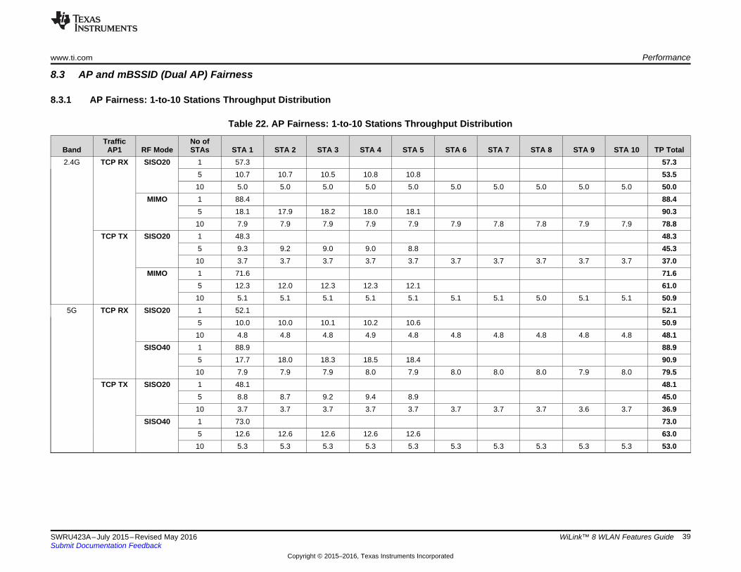
www.ti.com Performance
39SWRU423A–July 2015–Revised May 2016Submit Documentation Feedback
Copyright © 2015–2016, Texas Instruments Incorporated
WiLink™ 8 WLAN Features Guide
8.3 AP and mBSSID (Dual AP) Fairness
8.3.1 AP Fairness: 1-to-10 Stations Throughput Distribution
Table 22. AP Fairness: 1-to-10 Stations Throughput Distribution
BandTraffic
AP1 RF ModeNo ofSTAs STA 1 STA 2 STA 3 STA 4 STA 5 STA 6 STA 7 STA 8 STA 9 STA 10 TP Total
2.4G TCP RX SISO20 1 57.3 57.35 10.7 10.7 10.5 10.8 10.8 53.510 5.0 5.0 5.0 5.0 5.0 5.0 5.0 5.0 5.0 5.0 50.0
MIMO 1 88.4 88.45 18.1 17.9 18.2 18.0 18.1 90.310 7.9 7.9 7.9 7.9 7.9 7.9 7.8 7.8 7.9 7.9 78.8
TCP TX SISO20 1 48.3 48.35 9.3 9.2 9.0 9.0 8.8 45.310 3.7 3.7 3.7 3.7 3.7 3.7 3.7 3.7 3.7 3.7 37.0
MIMO 1 71.6 71.65 12.3 12.0 12.3 12.3 12.1 61.010 5.1 5.1 5.1 5.1 5.1 5.1 5.1 5.0 5.1 5.1 50.9
5G TCP RX SISO20 1 52.1 52.15 10.0 10.0 10.1 10.2 10.6 50.910 4.8 4.8 4.8 4.9 4.8 4.8 4.8 4.8 4.8 4.8 48.1
SISO40 1 88.9 88.95 17.7 18.0 18.3 18.5 18.4 90.910 7.9 7.9 7.9 8.0 7.9 8.0 8.0 8.0 7.9 8.0 79.5
TCP TX SISO20 1 48.1 48.15 8.8 8.7 9.2 9.4 8.9 45.010 3.7 3.7 3.7 3.7 3.7 3.7 3.7 3.7 3.6 3.7 36.9
SISO40 1 73.0 73.05 12.6 12.6 12.6 12.6 12.6 63.010 5.3 5.3 5.3 5.3 5.3 5.3 5.3 5.3 5.3 5.3 53.0
Performance www.ti.com
40 SWRU423A–July 2015–Revised May 2016Submit Documentation Feedback
Copyright © 2015–2016, Texas Instruments Incorporated
WiLink™ 8 WLAN Features Guide
8.3.2 mBSSID Fairness: 10 Stations Throughput Distribution
Table 23. AP Fairness: 10 Stations Connected to AP Throughput Distribution
BandTrafficAP1 RF Mode
AP1STAs
AP2STAs STA 1 STA 2 STA 3 STA 4 STA 5 STA 6 STA 7 STA 8 STA 9 STA 10 TP Total
2.4G TCP RX SISO20 10 0 4.6 4.5 4.6 4.5 4.5 4.6 4.6 4.6 4.5 4.5 45.57 3 3.2 3.2 3.2 3.2 3.2 3.2 3.2 7.9 7.2 7.1 44.65 5 4.4 4.5 4.4 4.4 4.4 4.5 4.5 4.4 4.4 4.4 44.3
MIMO 10 0 6.6 6.6 6.6 6.6 6.5 6.5 6.5 6.5 6.6 6.6 65.67 3 4.7 4.6 4.6 4.6 4.6 4.6 4.6 11.5 11.5 11.1 66.45 5 6.6 6.6 6.6 6.6 6.6 6.6 6.6 6.6 6.6 6.6 66.0
TCP TX SISO20 10 0 3.3 3.3 3.3 3.3 3.3 3.3 3.3 3.3 3.3 3.3 33.07 3 2.3 2.3 2.3 2.3 2.3 2.3 2.3 5.7 5.4 5.2 32.45 5 3.2 3.2 3.2 3.2 3.2 3.2 3.2 3.2 3.2 3.2 32.0
MIMO 10 0 4.5 4.5 4.5 4.3 4.5 4.5 4.5 4.4 4.5 4.5 44.77 3 3.0 3.0 3.0 3.0 3.0 3.0 3.0 7.2 7.2 6.9 42.35 5 4.2 4.2 4.2 4.2 4.2 4.2 4.2 4.2 4.2 4.2 42.0
5G TCP RX SISO20 10 0 4.5 4.5 4.5 4.6 4.3 4.4 4.3 4.4 4.5 4.3 44.37 3 3.1 3.1 3.1 3.1 3.0 3.1 3.1 7.2 7.3 7.2 43.35 5 4.3 4.2 4.2 4.4 4.3 4.2 4.3 4.2 4.3 4.2 42.6
SISO40 10 0 6.9 6.9 7.0 7.0 6.9 6.9 6.9 6.7 7.0 6.9 69.17 3 4.7 4.7 4.7 4.7 4.7 4.8 4.5 11.4 11.6 11.7 67.55 5 6.6 6.7 6.7 6.8 6.8 6.7 6.8 6.8 6.8 6.8 67.5
TCP TX SISO20 10 0 3.3 3.3 3.3 3.2 3.3 3.3 3.2 3.3 3.3 3.3 32.87 3 2.3 2.3 2.3 2.3 2.3 2.3 2.3 5.4 5.4 5.3 32.25 5 3.2 3.2 3.2 3.2 3.2 3.0 3.2 3.2 3.2 3.1 31.7
SISO40 10 0 4.6 4.6 4.6 4.6 4.6 4.6 4.6 4.7 4.6 4.6 46.17 3 3.2 3.2 3.2 3.2 3.2 3.2 3.2 7.2 7.7 7.5 44.85 5 4.5 4.4 4.4 4.3 4.4 4.5 4.5 4.5 4.5 4.5 44.5

www.ti.com Performance
41SWRU423A–July 2015–Revised May 2016Submit Documentation Feedback
Copyright © 2015–2016, Texas Instruments Incorporated
WiLink™ 8 WLAN Features Guide
8.4 Bluetooth WLAN CoexistenceWLAN and Bluetooth operate at the same RF band and must share it to exist concurrently for theiroperation, despite using a different air access mechanism and modulation. As a result, a single radio at a2.4-GHz band can be used and shared between them. This mechanism permits a full control of theBluetooth and WLAN IP air access.
The WLAN-BT coexistence performance results depend on several parameters, which can impact theoverall system behavior and performance. Bluetooth modulation, packet type, or bandwidth can impactWLAN throughput performance. This is because Bluetooth, during eSCO and A2DP, has a higher priorityover WLAN. The A2DP rate, for example, also impacts WLAN performance.
All results in Table 24 relate to a specific system configuration, and will vary depending on Bluetooth andWLAN parameters and peer device capabilities.
8.4.1 WLAN Single Role – Bluetooth Performance
Table 24. WLAN Single Role – Bluetooth Coexistence
DUT RoleBluetooth/BLETraffic Settings WLAN Traffic
WLAN TP [Mbps]2.4GHz 5GHz
SISO20 MIMO20 SISO20 SISO40SUT Hands Free 2EV3 1 Retry TCP TX 22 26 50 93
TCP RX 21 24 60 117A2DP Sink 350 kbps TCP TX 20 32 51 87
TCP RX 22 41 60 102A2DP Source 350 kbps TCP TX 35 56 50 93
TCP RX 39 70 60 115FTP CLT TX 1 Mbps TCP TX 25 42 52 88
TCP RX 26 50 60 91BLE Advertise Every 110 mSec TCP TX 46 72 48 79
TCP RX 57 76 59 109BLE Discovery Interval : 60 mSec TCP TX 49 34 48 78
Window Size : 20 mSec TCP RX 59 45 59 109APUT HF 2EV3 1 Retry TCP TX 16 18 48 79
TCP RX 20 21 58 108A2DP Sink 350 kbps TCP TX 24 36 51 77
TCP RX 26 35 59 98A2DP Source 350 kbps TCP TX 27 40 50 80
TCP RX 31 42 61 109FTP CLT TX 1 Mbps TCP TX 25 37 50 74
TCP RX 29 39 58 87BLE Advertise Every 110 mSec TCP TX 48 83 49 93
TCP RX 56 105 60 118BLE Discovery Interval: 60 mSec TCP TX 29 48 50 93
Window Size: 20 mSec TCP RX 34 62 60 118CLUT HF 2EV3 1 Retry TCP TX 17 21 50 80
TCP RX 23 20 60 111A2DP Sink 350kbps TCP TX 19 26 51 77
TCP RX 22 27 61 100A2DP Source 350kbps TCP TX 34 48 50 80
TCP RX 40 49 61 110FTP CLT TX 1Mbps TCP TX 24 35 51 76
TCP RX 28 34 57 90

Performance www.ti.com
42 SWRU423A–July 2015–Revised May 2016Submit Documentation Feedback
Copyright © 2015–2016, Texas Instruments Incorporated
WiLink™ 8 WLAN Features Guide
Table 24. WLAN Single Role – Bluetooth Coexistence (continued)
DUT RoleBluetooth/BLETraffic Settings WLAN Traffic
WLAN TP [Mbps]2.4GHz 5GHz
SISO20 MIMO20 SISO20 SISO40GOUT HF 2EV3 1 Retry TCP TX 17 20 50 79
TCP RX 22 21 60 111A2DP Sink 350kbps TCP TX 24 34 51 76
TCP RX 26 30 60 101A2DP Source 350kbps TCP TX 27 40 50 79
TCP RX 31 38 61 112FTP CLT TX 1Mbps TCP TX 25 39 51 75
TCP RX 29 35 61 88
www.ti.com Revision History
43SWRU423A–July 2015–Revised May 2016Submit Documentation Feedback
Copyright © 2015–2016, Texas Instruments Incorporated
Revision History
Revision HistoryNOTE: Page numbers for previous revisions may differ from page numbers in the current version.
Changes from Original (July 2015) to A Revision ........................................................................................................... Page
• Changed title of this document. ......................................................................................................... 5• Updated Table 2. .......................................................................................................................... 5• Updated Table 3. .......................................................................................................................... 7• Updated Section 2.6. .................................................................................................................... 14• Section 2.11 was updated and moved to its current location in the document. ................................................. 17• Updated Section 3.5.1................................................................................................................... 22• Added new Section 6. ................................................................................................................... 33• Updated Section 6.1.1................................................................................................................... 34• Updated Table 18. ....................................................................................................................... 35• Updated Section 7.2. .................................................................................................................... 36• Updated Table 19. ....................................................................................................................... 36
IMPORTANT NOTICE
Texas Instruments Incorporated and its subsidiaries (TI) reserve the right to make corrections, enhancements, improvements and otherchanges to its semiconductor products and services per JESD46, latest issue, and to discontinue any product or service per JESD48, latestissue. Buyers should obtain the latest relevant information before placing orders and should verify that such information is current andcomplete. All semiconductor products (also referred to herein as “components”) are sold subject to TI’s terms and conditions of salesupplied at the time of order acknowledgment.TI warrants performance of its components to the specifications applicable at the time of sale, in accordance with the warranty in TI’s termsand conditions of sale of semiconductor products. Testing and other quality control techniques are used to the extent TI deems necessaryto support this warranty. Except where mandated by applicable law, testing of all parameters of each component is not necessarilyperformed.TI assumes no liability for applications assistance or the design of Buyers’ products. Buyers are responsible for their products andapplications using TI components. To minimize the risks associated with Buyers’ products and applications, Buyers should provideadequate design and operating safeguards.TI does not warrant or represent that any license, either express or implied, is granted under any patent right, copyright, mask work right, orother intellectual property right relating to any combination, machine, or process in which TI components or services are used. Informationpublished by TI regarding third-party products or services does not constitute a license to use such products or services or a warranty orendorsement thereof. Use of such information may require a license from a third party under the patents or other intellectual property of thethird party, or a license from TI under the patents or other intellectual property of TI.Reproduction of significant portions of TI information in TI data books or data sheets is permissible only if reproduction is without alterationand is accompanied by all associated warranties, conditions, limitations, and notices. TI is not responsible or liable for such altereddocumentation. Information of third parties may be subject to additional restrictions.Resale of TI components or services with statements different from or beyond the parameters stated by TI for that component or servicevoids all express and any implied warranties for the associated TI component or service and is an unfair and deceptive business practice.TI is not responsible or liable for any such statements.Buyer acknowledges and agrees that it is solely responsible for compliance with all legal, regulatory and safety-related requirementsconcerning its products, and any use of TI components in its applications, notwithstanding any applications-related information or supportthat may be provided by TI. Buyer represents and agrees that it has all the necessary expertise to create and implement safeguards whichanticipate dangerous consequences of failures, monitor failures and their consequences, lessen the likelihood of failures that might causeharm and take appropriate remedial actions. Buyer will fully indemnify TI and its representatives against any damages arising out of the useof any TI components in safety-critical applications.In some cases, TI components may be promoted specifically to facilitate safety-related applications. With such components, TI’s goal is tohelp enable customers to design and create their own end-product solutions that meet applicable functional safety standards andrequirements. Nonetheless, such components are subject to these terms.No TI components are authorized for use in FDA Class III (or similar life-critical medical equipment) unless authorized officers of the partieshave executed a special agreement specifically governing such use.Only those TI components which TI has specifically designated as military grade or “enhanced plastic” are designed and intended for use inmilitary/aerospace applications or environments. Buyer acknowledges and agrees that any military or aerospace use of TI componentswhich have not been so designated is solely at the Buyer's risk, and that Buyer is solely responsible for compliance with all legal andregulatory requirements in connection with such use.TI has specifically designated certain components as meeting ISO/TS16949 requirements, mainly for automotive use. In any case of use ofnon-designated products, TI will not be responsible for any failure to meet ISO/TS16949.
Products ApplicationsAudio www.ti.com/audio Automotive and Transportation www.ti.com/automotiveAmplifiers amplifier.ti.com Communications and Telecom www.ti.com/communicationsData Converters dataconverter.ti.com Computers and Peripherals www.ti.com/computersDLP® Products www.dlp.com Consumer Electronics www.ti.com/consumer-appsDSP dsp.ti.com Energy and Lighting www.ti.com/energyClocks and Timers www.ti.com/clocks Industrial www.ti.com/industrialInterface interface.ti.com Medical www.ti.com/medicalLogic logic.ti.com Security www.ti.com/securityPower Mgmt power.ti.com Space, Avionics and Defense www.ti.com/space-avionics-defenseMicrocontrollers microcontroller.ti.com Video and Imaging www.ti.com/videoRFID www.ti-rfid.comOMAP Applications Processors www.ti.com/omap TI E2E Community e2e.ti.comWireless Connectivity www.ti.com/wirelessconnectivity
Mailing Address: Texas Instruments, Post Office Box 655303, Dallas, Texas 75265Copyright © 2016, Texas Instruments Incorporated