Wilcom€¦ · These limits are de- ... manual, may cause harmful interference to radio com- ......
23
FS Series Fiber Laser Sources OPERATING INSTRUCTIONS Wilcom
Transcript of Wilcom€¦ · These limits are de- ... manual, may cause harmful interference to radio com- ......
FS Series Fiber Laser Sources
OPERATINGINSTRUCTIONS
Wilcom
Copyright (c) 2007 WilcomAll Rights reserved
Wilcom reserves the right to make changes to thematerial contained herein without notice and shall not beresponsible for any damages caused by reliance on thematerial presented.
This document may not be copied or duplicated in partor in whole for any purpose without the express writtenpermission of Wilcom.
ST is a trademark of AT&T.
FS Series Fiber Laser SourcesOperating Instructions
812-694-005March, 2007
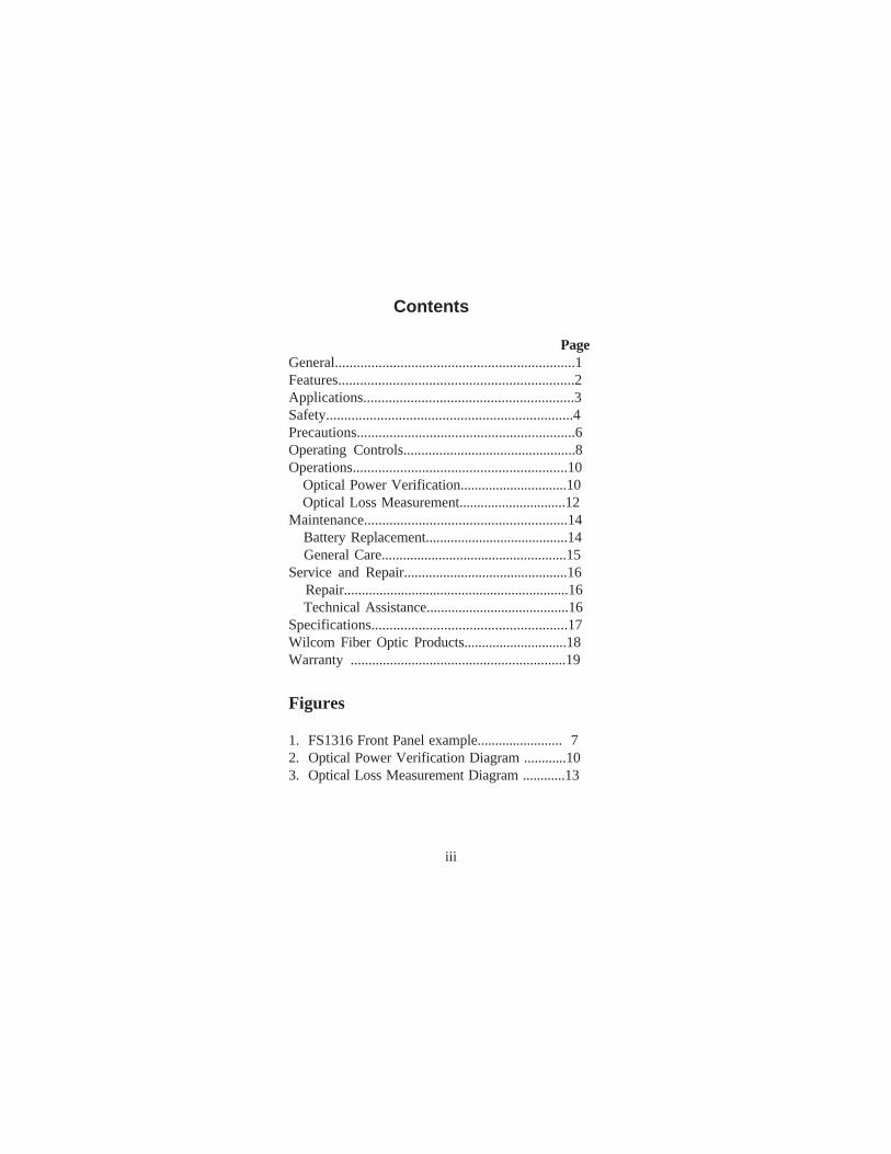
Contents
PageGeneral..................................................................1Features.................................................................2Applications..........................................................3Safety....................................................................4Precautions............................................................6Operating Controls................................................8Operations...........................................................10 Optical Power Verification..............................10 Optical Loss Measurement..............................12Maintenance........................................................14 Battery Replacement........................................14 General Care....................................................15Service and Repair..............................................16 Repair...............................................................16 Technical Assistance........................................16Specifications......................................................17Wilcom Fiber Optic Products.............................18Warranty ............................................................19
Figures
1. FS1316 Front Panel example........................ 72. Optical Power Verification Diagram ............103. Optical Loss Measurement Diagram ............13
iii
General
iv
Model FS1316
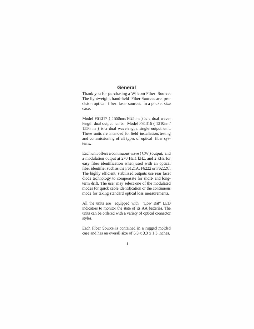
GeneralThank you for purchasing a Wilcom Fiber Source.The lightweight, hand-held Fiber Sources are pre-cision optical fiber laser sources in a pocket sizecase.
Model FS1317 ( 1550nm/1625nm ) is a dual wave-length dual output units. Model FS1316 ( 1310nm/1550nm ) is a dual wavelength, single output unit.These units are intended for field installation, testingand commissioning of all types of optical fiber sys-tems.
Each unit offers a continuous wave ( CW ) output, anda modulation output at 270 Hz,1 kHz, and 2 kHz foreasy fiber identification when used with an opticalfiber identifier such as the F6121A, F6222 or F6222C.The highly efficient, stabilized outputs use rear facetdiode technology to compensate for short- and long-term drift. The user may select one of the modulatedmodes for quick cable identification or the continuousmode for taking standard optical loss measurements.
All the units are equipped with "Low Bat" LEDindicators to monitor the state of its AA batteries. Theunits can be ordered with a variety of optical connectorstyles.
Each Fiber Source is contained in a rugged moldedcase and has an overall size of 6.3 x 3.3 x 1.3 inches.
1
• 1310 and 1550nm wavelengths ( FS1316 )( single output port )
• 1550 and 1625nm wavelengths ( FS1317 )( dual output ports )
• FC, SC or ST type optical connectors
• Output Power adjust for each wavelength
• Multimode and Singlemode operation
• Accurate and stable
• Cable identification mode
• Modulation capability( CW, 270Hz, 1KHz, and 2KHz )
• Pocket size, robust, and lightweight
• Membrane switch overlay
• Visual output indication
• Easy to use
Features
2
• Cable and link loss measurement
• Network auditing and maintenance
• Troubleshooting and repair
• Connector and coupling losses
• Field test and repair
• Bare fiber loss measurement
• Fiber identification
Applications
3
1 American National Standard for Safe Use of Lasers, Publica-tion: ANSI Z136.I-1993, American National Standards Institute,11 West 42nd Street, New York, NY 110036
Wilcom Models FS1316, and FS1317 Fiber Sources area Class I laser product under the requirements of theU.S. Center for Devices and Radiological Health andthe American Standard Institute1. As such it presents nohazard to users who view the output when using properoperating procedures. However, it is recommended thatusers should not stare directly into the beam.
Use of controls or adjustments of procedures other thanthose specified may result in hazardous LASER lightexposure.
Safety
4
NOTE: This equipment has been tested and found tocomply with the limits for a Class A digital device, pur-suant to Part 15 of the FCC Rules. These limits are de-signed to provide reasonable protection against harm-ful interference when equipment is operated in a com-mercial environment. This equipment generates, uses,and can radiate radio frequency energy, and if not in-stalled and used in accordance with the instructionmanual, may cause harmful interference to radio com-munications. Operation of this equipment in a residen-tial area is likely to cause harmful interference in whichcase the user will be required to correct the interferenceat his own expense.
Safety (cont.)
5
Use care when working with any optical transmissionequipment. It is good practice to avoid looking directlyat any optical fibers or optical sources. Each of theWilcom Fiber Sources emits laser light, and one shouldnot look directly into the connector port. It is best to referto your company's safety procedures when working withoptical systems.
It is important to keep all optical connections andsurfaces free from dirt, oils or other contamination toensure proper operation. This applies to all connectorsthat are connected to the optical port on the any one ofthe Fiber Sources, as well as the optical port itself.Scratched or contaminated connectors can reduce sys-tem performance. Refer to your company practices forcleaning optical connectors. Always replace the protec-tive dust cap after use.
Precautions
6
Wilcom
1
4
6
3
7
10
5
8
2
Operating Controls
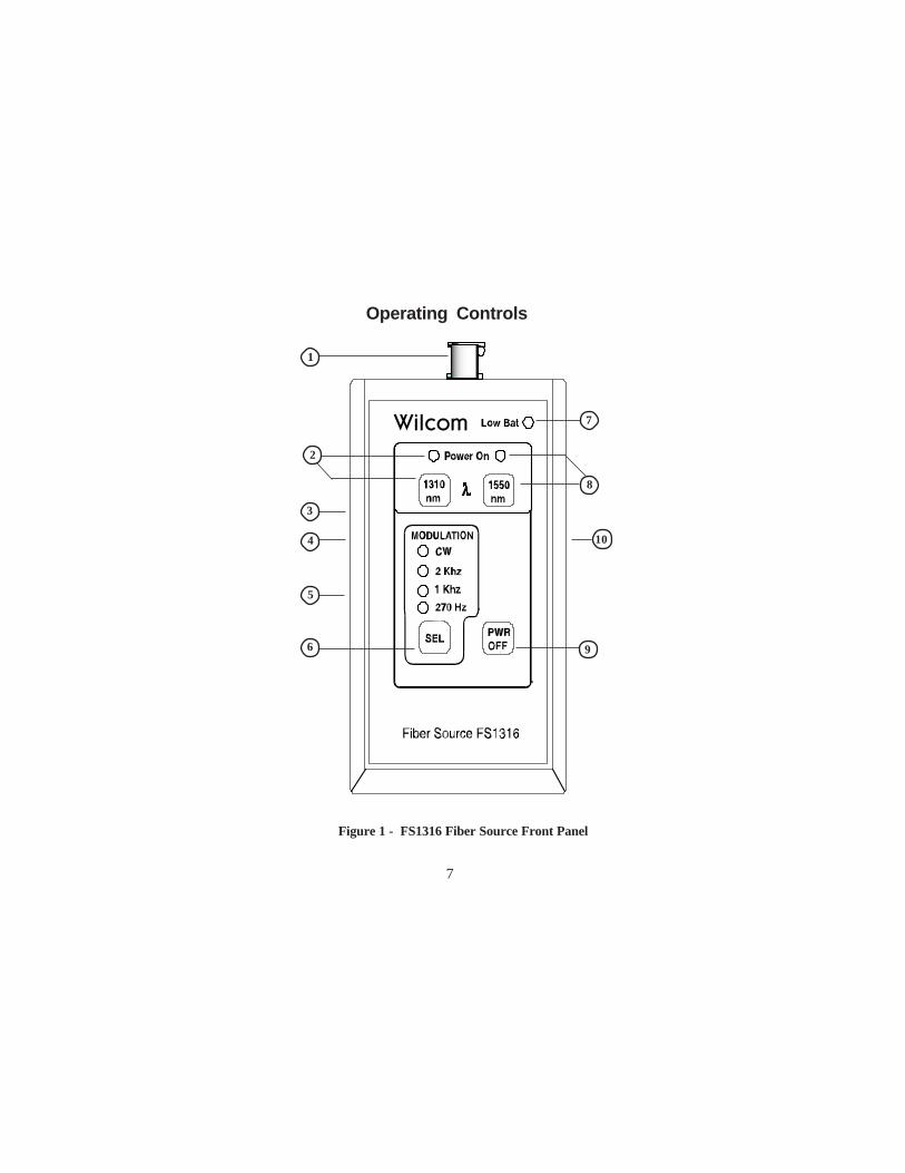
Figure 1 - FS1316 Fiber Source Front Panel
7
9
Operating Controls
1
2 8
8
3
Note: Wilcom Models FS1317, and FS1316 looksimilar except for the number of optical output portsand the wavelengths. Figure 1.0 is for referencepurposes only.
FS1317 - Standard with dual optical portsavailable with either an ST, SC, or FC connector.
FS1316 - Standard with a single optical portavailable with either an ST, SC, or FC connector.
Wavelength selection is done by depressingthe desired wavelength key. An LED illuminatesindicating the desired selection
The absolute Output Power level of the1310nm wavelength on Model FS1316 may be ad-justed by approximately ±1 dB.
1
Operating Controls (cont.)
9
5
7
9
4
6
The absolute Output Power level of the1550nm wavelength on Models FS1317 and FS1316may be adjusted by approximately ±1 dB.
Optional charger jack port used only withNiCad batteries.
The SEL key when depressed selects one offour modulations , 270, 1kHz, 2kHz or CW, and allowsthe output to be modulated at 270 Hz, 1kHz,2kHz, or continuous wave, respectively.
Low Bat LED illuminates when the batteryvoltage has dropped below a working level. Whenbattery voltage falls far enough, the Laser and its asso-ciated LED will shut off.
The PWR OFF key when depressed turns offthe Fiber Source. The battery compartment holds twoAA Alkaline or NiCad batteries.
The absolute Output Power level of the1625nm wavelength on Model FS1317 may be adjustedby approximately ±1 dB.
10
Operation
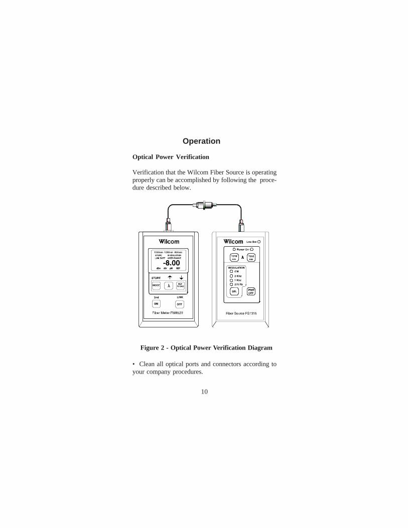
Optical Power Verification
Verification that the Wilcom Fiber Source is operatingproperly can be accomplished by following the proce-dure described below.
• Clean all optical ports and connectors according toyour company procedures.
Figure 2 - Optical Power Verification Diagram
10
Operation (cont.)
11
• Connect a patch cable to the Wilcom Laser Source.
• Connect a patch cable to a power meter such asWilcom Models FM8510, FM8515B/C, FM8520 orFM1317.
• Connect the ends of the patch cables together using acoupling device.
• Turn on the Wilcom Fiber Laser Source and set to1310nm. The unit will stabilize very quickly.
• Turn on the power meter and set the wavelength to1310nm.
• Adjust the output of the Wilcom Fiber Laser Sourceuntil the power meter reads - 08.0 dBm. (Note: Thelaunch output power of the Wilcom Laser Source is-08.0 dBm with an output adjust control of ± 1.0 dB.)
• Record the power meter reading . This measure-ment will be the reference level.
Note: An important consideration is the wavelength ofthe optical signal. Both the Fiber Laser Source and thepower meter must be set at the same wavelength toensure accurate measurements. The above exampledescribes 1310nm testing. To test 1550nm or 850nm,simply set both the Wilcom Fiber Laser Source and thepower meter to either 1550nm or 850nm.
Operation (cont.)Optical Loss Measurements
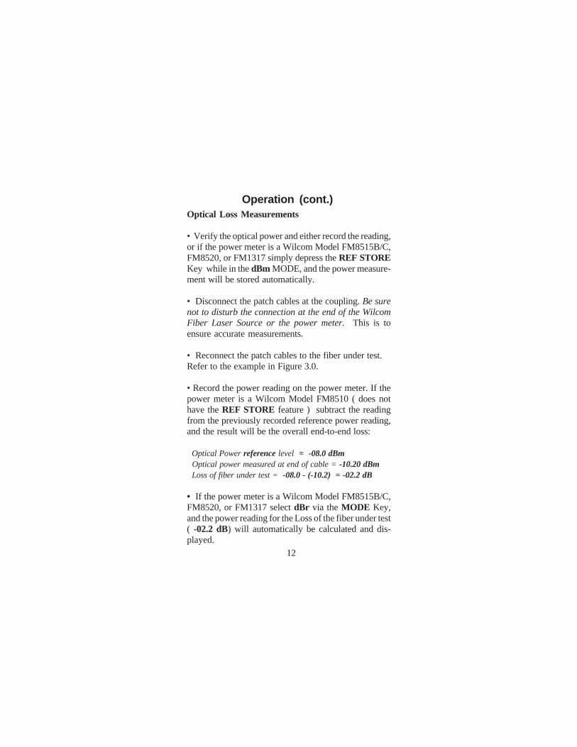
• Verify the optical power and either record the reading,or if the power meter is a Wilcom Model FM8515B/C,FM8520, or FM1317 simply depress the REF STOREKey while in the dBm MODE, and the power measure-ment will be stored automatically.
• Disconnect the patch cables at the coupling. Be surenot to disturb the connection at the end of the WilcomFiber Laser Source or the power meter. This is toensure accurate measurements.
• Reconnect the patch cables to the fiber under test.Refer to the example in Figure 3.0.
• Record the power reading on the power meter. If thepower meter is a Wilcom Model FM8510 ( does nothave the REF STORE feature ) subtract the readingfrom the previously recorded reference power reading,and the result will be the overall end-to-end loss:
Optical Power reference level = -08.0 dBm Optical power measured at end of cable = -10.20 dBm Loss of fiber under test = -08.0 - (-10.2) = -02.2 dB
• If the power meter is a Wilcom Model FM8515B/C,FM8520, or FM1317 select dBr via the MODE Key,and the power reading for the Loss of the fiber under test( -02.2 dB) will automatically be calculated and dis-played.
12
Operation (cont.)
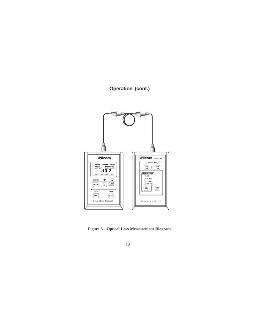
Figure 3 - Optical Loss Measurement Diagram
13
Battery ReplacementThe Fiber Sources require no periodic maintenanceother than replacing the batteries. Under normal use thetwo AA alkaline batteries should provide greater than25 hours of continuous use. To replace battery, place theunit with its back side facing up. Use a small screwdriverto remove the two screws and release battery cover.Install battery and then secure cover to unit with screws.
Optional Battery Charger
When the Fiber Sources are purchased with the optional batterycharger, they are shipped with two AA NiCd rechargeablebatteries. The batteries have been kept in the uncharged state forshipment. Therefore, be sure to fully charge it before use.
To charge the batteries, simply plug the charger's transformerinto an AC outlet and the other end into the charger jack on theFiber Source. Charge the unit overnight ( about 14 hours). Thebatteries may be charged with any battery charger with thefollowing specifications:
INPUT: AC 120V~, 60 Hz in the USA and CanadaAC 110-240 V~, 50/60 Hz in other countries
OUTPUT: 8.7-15 V AC or DC @>150mA,2.1 mm coax jack (Tip - Positive)
Important — When charging batteries in unit, pleasebe sure to use only NiCd batteries. Charging anyother type of battery will cause damage to unit.
Maintenance
14
General CareTo avoid damage to the Fiber Sources, do not use cableconnectors that are dirty or faulty. A dust cap is providedfor the optical output port, and should be in place whenthe unit is not in use to prevent foreign material fromentering the port. It is best to clean the connectors first,using cotton swabs and isopropyl alcohol.
To clean the inside of the optical connector, use only asmall diameter cotton swab lightly moistened withisopropyl alcohol.
Clean the Fiber Source's body with a damp cloth. Do notuse solvents or abrasives.
Maintenance (cont)
15
Service and Repair
16
For service or repair follow the procedure below:
1. Call Wilcom Customer Service. Support personnel willdetermine if the equipment requires service, repair or calibra-tion.
2. If the equipment must be returned to Wilcom for service,Wilcom Customer Service will issue a Return Material Autho-rization (RMA) number and the following address for return:
Wilcom 73 Daniel Webster Highway Belmont, NH 03220 TEL (800) 222-1898 (USA only) or (603) 524-2622 FAX (603) 524-3735 www.wilcominc.com
IMPORTANT
Never send any equipment back to Wilcom without aReturn Material Authorization (RMA) number.
3. Pack the equipment in its original shipping material. Be sureto include a statement or report fully detailing the defect andconditions under which it was observed. Also be sure toinclude a contact name and telephone number.
4. Return the equipment, prepaid, to the above address. Besure to write the RMA on the shipping slip. Wilcom will refuseand return any package that does not bear the RMA.
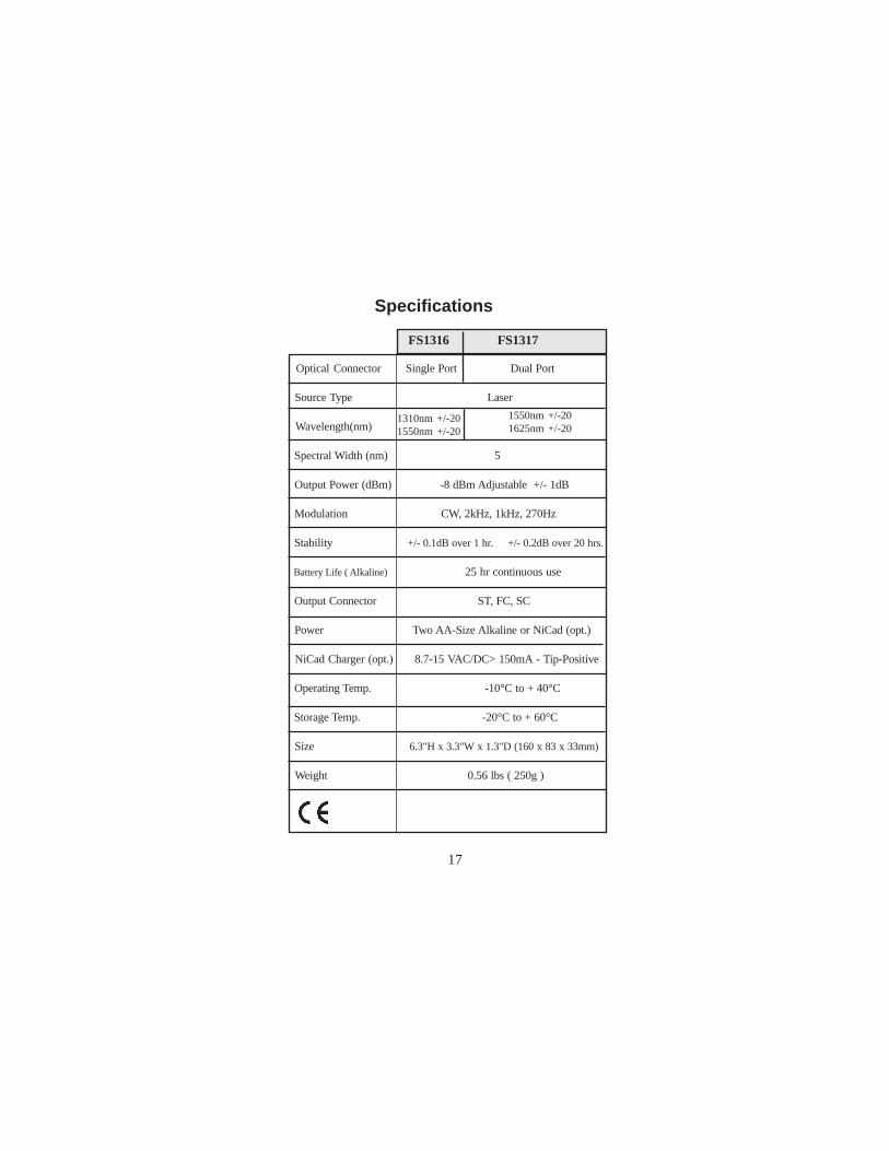
Specifications
FS1316 FS1317
1310nm +/-201550nm +/-20
1550nm +/-201625nm +/-20
17
Optical Connector Single Port Dual Port
Source Type Laser
Wavelength(nm)
Spectral Width (nm) 5
Output Power (dBm) -8 dBm Adjustable +/- 1dB
Modulation CW, 2kHz, 1kHz, 270Hz
Stability +/- 0.1dB over 1 hr. +/- 0.2dB over 20 hrs.
Battery Life ( Alkaline) 25 hr continuous use
Output Connector ST, FC, SC
Power Two AA-Size Alkaline or NiCad (opt.)
NiCad Charger (opt.) 8.7-15 VAC/DC> 150mA - Tip-Positive
Operating Temp. -10°C to + 40°C
Storage Temp. -20°C to + 60°C
Size 6.3"H x 3.3"W x 1.3"D (160 x 83 x 33mm)
Weight 0.56 lbs ( 250g )
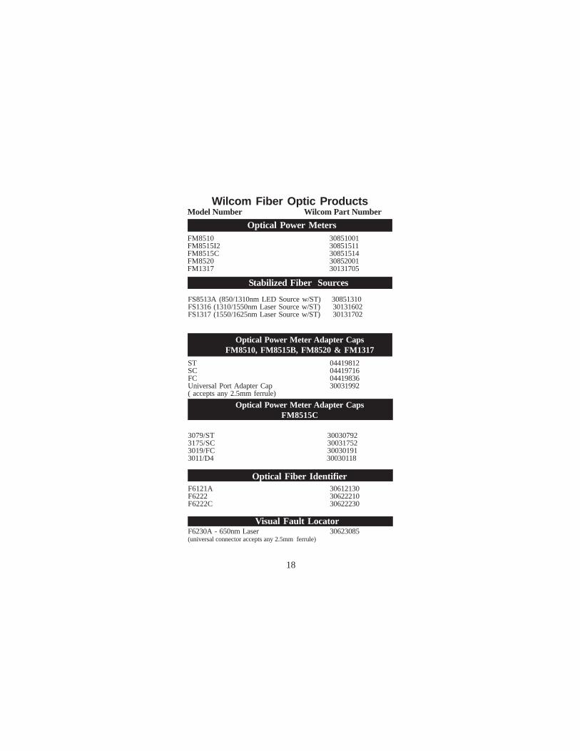
Wilcom Fiber Optic Products
FM8510 30851001FM8515I2 30851511FM8515C 30851514FM8520 30852001FM1317 30131705
ST 04419812SC 04419716FC 04419836Universal Port Adapter Cap 30031992( accepts any 2.5mm ferrule)
Stabilized Fiber Sources
Optical Power Meters
FS8513A (850/1310nm LED Source w/ST) 30851310FS1316 (1310/1550nm Laser Source w/ST) 30131602FS1317 (1550/1625nm Laser Source w/ST) 30131702
Optical Fiber IdentifierF6121A 30612130F6222 30622210F6222C 30622230
Visual Fault LocatorF6230A - 650nm Laser 30623085(universal connector accepts any 2.5mm ferrule)
Optical Power Meter Adapter CapsFM8510, FM8515B, FM8520 & FM1317
18
Model Number Wilcom Part Number
Optical Power Meter Adapter CapsFM8515C
3079/ST 300307923175/SC 300317523019/FC 300301913011/D4 30030118
WARRANTYAll products are warranted against defects in materials and workman-ship. This warranty applies for a period of two (2) years from date ofdelivery, except for Fiber Optic instrumentation and equipmentwhich have a one (1) year warranty on parts and two (2) years on labor.(The only exception in the digital testing equipment is the D550Shark, which has a warranty of one (1) year from date of delivery.)Wilcom's obligation under this warranty is limited to servicing oradjusting each instrument returned to its factory within the warrantyperiod, and to replace any components found to be defective. Ifdetermined that the defective condition is a result of misuse orabnormal operation, repairs will be billed.
LIMITATION OF WARRANTYThe foregoing warranties are the exclusive warranties provided byWilcom. Wilcom will not be liable for any special, indirect, incidentalor consequential damages whatsoever resulting from loss of use, lossof data or loss of profits arising out of or in connection with the useor performance of the product, even if Wilcom has been informed ofthe possibility of such damages in advance. All implied warranties,including without limitation warranties of merchantability and fit-ness for a particular purpose, as well as warranties arising from acourse of dealing or usage of trade are expressly disclaimed.
PROPRIETARY INFORMATIONThe information contained in this manual is the proprietary materialof Wilcom, and may not be reproduced, used for manufacturingpurposes, or disclosed to others for any use without written permis-sion from Wilcom.
19