
Wiggin and Dana llp Bruce L. McDermott One …€¦ · Bruce L. McDermott 203.498.4340 ... 24 and...
38
New Haven Stamford New York Hartford Philadelphia Bruce L. McDermott 203.498 .4340 203.782.2889 fax [email protected] Wiggin and Dana llp One Century Tower P.O. Box 1832 New Haven, Connecticut 06508-1832 www.wiggin.com VIA MESSENGER May 25, 2004 Pamela B. Katz Chairman Connecticut Siting Council Ten Franklin Square New Britain, CT 06051 Re: Docket 272 - The Connecticut Light and Power Company and The United Illuminating Company Application for a Certificate of Environmental Compatibility and Public Need for the Construction of a New 345-kV Electric Transmission Line and Associated Facilities Between Scovill Rock Switching Station in Middletown and Norwalk Substation in Norwalk, Connecticut Including the Reconstruction of Portions of Existing 115-kV and 345-kV Electric Transmission Lines, the Construction of the Beseck Switching Station in Wallingford, East Devon Substation in Milford, and Singer Substation in Bridgeport, Modifications at Scovill Rock Switching Station and Norwalk Substation and the Reconfiguration of Certain Interconnections Dear Chairman Katz: I enclose an original and twenty copies of the Pre-file Testimony of The Connecticut Light and Power Company and The United Illuminating Company regarding “Routing and Environmental Matters Concerning the Portion of the Project between Scovill Rock Switching Station and East Devon Substation (Segments 1 & 2)”. If you have any questions about this filing, please do not hesitate to contact me. Very truly yours, Bruce L. McDermott cc: Service List Enclosures 10705\1209\468638.1
Transcript of Wiggin and Dana llp Bruce L. McDermott One …€¦ · Bruce L. McDermott 203.498.4340 ... 24 and...
New Haven Stamford New York Hartford Philadelphia
Bruce L. McDermott 203.498.4340 203.782.2889 fax [email protected]
Wiggin and Dana llp One Century Tower P.O. Box 1832 New Haven, Connecticut 06508-1832 www.wiggin.com
VIA MESSENGER
May 25, 2004
Pamela B. Katz Chairman Connecticut Siting Council Ten Franklin Square New Britain, CT 06051 Re: Docket 272 - The Connecticut Light and Power Company and The United Illuminating
Company Application for a Certificate of Environmental Compatibility and Public Need for the Construction of a New 345-kV Electric Transmission Line and Associated Facilities Between Scovill Rock Switching Station in Middletown and Norwalk Substation in Norwalk, Connecticut Including the Reconstruction of Portions of Existing 115-kV and 345-kV Electric Transmission Lines, the Construction of the Beseck Switching Station in Wallingford, East Devon Substation in Milford, and Singer Substation in Bridgeport, Modifications at Scovill Rock Switching Station and Norwalk Substation and the Reconfiguration of Certain Interconnections
Dear Chairman Katz:
I enclose an original and twenty copies of the Pre-file Testimony of The Connecticut Light and Power Company and The United Illuminating Company regarding “Routing and Environmental Matters Concerning the Portion of the Project between Scovill Rock Switching Station and East Devon Substation (Segments 1 & 2)”. If you have any questions about this filing, please do not hesitate to contact me. Very truly yours,
Bruce L. McDermott
cc: Service List
Enclosures
10705\1209\468638.1
1
STATE OF CONNECTICUT
SITING COUNCIL
Re: The Connecticut Light and Power Company and The United Illuminating Company Application for a Certificate of Environmental Compatibility and Public Need for the Construction of a New 345-kV Electric Transmission Line and Associated Facilities Between Scovill Rock Switching Station in Middletown and Norwalk Substation in Norwalk, Connecticut Including the Reconstruction of Portions of Existing 115-kV and 345-kV Electric Transmission Lines, the Construction of the Beseck Switching Station in Wallingford, East Devon Substation in Milford, and Singer Substation in Bridgeport, Modifications at Scovill Rock Switching Station and Norwalk Substation and the Reconfiguration of Certain Interconnections
) ) ) ) ) ) ) ) ) ) ) ) ) ) )
Docket 272 May 25, 2004
DIRECT TESTIMONY OF ROGER ZAKLUKIEWICZ, ANNE BARTOSEWICZ, JOHN PRETE, RICHARD REED, JAMES HOGAN, CYRIL WETLER, AND
LOUISE MANGO REGARDING ROUTING AND ENVIRONMENTAL MATTERS CONCERNING THE PORTION OF THE MIDDLETOWN TO
NORWALK PROJECT BETWEEN SCOVILL ROCK SWITCHING STATION AND EAST DEVON SUBSTATION (SEGMENTS 1 & 2)_
1
EXECUTIVE SUMMARY 2
Q. Would you please identify yourself and the other members of the panel 3
who will respond to cross examination regarding environmental matters? 4
A. I am Roger Zaklukiewicz, Vice President, Transmission Projects, 5
employed by Northeast Utilities Service Company (“NUSCO”), on behalf of The 6
Connecticut Light and Power Company (“CL&P”). With me on this panel are Anne 7
Bartosewicz, NUSCO Project Director, Transmission Projects; John Prete, Project 8
2
Director for The United Illuminating Company (“UI”); Richard Reed, Vice President, UI 9
Electric System; James Hogan and Cyril Welter from the Companies’ engineering 10
consultant, Burns & McDonnell; and Louise Mango, an environmental consultant from 11
Phenix Environmental, Inc. The resumes of these panel members are attached to our 12
direct testimony that was previously filed with the Connecticut Siting Council or have 13
already been made an exhibit in this proceeding. 14
Q. Do the Companies expect to call on any other personnel to respond to 15
routing or environmental issues? 16
A. Other UI employees, NU employees, and specialized Project consultants 17
may be called upon to respond to questions relating to specific routing, engineering 18
design, or environmental topics. These include NU employees Jeffrey Borne and Donald 19
Biondi. Project consultants include Kenneth Stevens, Registered Professional Soil 20
Scientist from Soil Science and Environmental Services, Inc. (“SSES”), the firm that 21
performed wetland and amphibian studies for the Project; Michael Raber of Raber 22
Associates (“Raber”), the firm that performed cultural resource studies for the Project; 23
and Douglas Bell of Cavanaugh Tocci Associates, Inc., the firm that conducted noise 24
studies of Scovill Rock Switching Station, the proposed Beseck Switching Station, and 25
the proposed East Devon Substation. 26
Q. What is the purpose of your testimony? 27
A. The purpose of this testimony is to provide an overview of the 45-mile 28
overhead portion of the Project (Segments 1 and 2) and to summarize the routing criteria 29
relevant to the development and analysis of plans for this portion of the route, which 30
would encompass the area from the Scovill Rock Switching Station in Middletown to the 31
3
new Beseck Switching Station in Wallingford and thence to the new East Devon 32
Substation in Milford. In addition, certain of the municipalities along the proposed route 33
requested that the Companies review a routing option for the northern portion of Segment 34
1 (referred to herein as the “Northerly Route”) that would traverse between Chestnut 35
Junction and Black Pond Junction. Likewise, during the April 2004 hearings, the Siting 36
Council asked the Companies whether a new switching station could be developed at 37
Black Pond Junction (in Meriden), rather than at Beseck (Wallingford), as proposed. The 38
testimony summarizes the results of the Companies’ review of both of these suggestions. 39
The testimony also describes how the avoidance or minimization of 40
environmental effects were considered in identifying the proposed route, and will 41
continue to be important as the Project design, certification, permitting, and construction 42
proceed. Environmental matters regarding the proposed Beseck Switching Station also 43
are reviewed. 44
Eight primary topics are discussed, as listed below. The first four topics pertain to 45
routing matters, while the latter four relate principally to environmental issues. 46
Routing: 47
48
1. General location of Segments 1 and 2, including the supported route 49 change in Cheshire (identified in the Companies’ Siting Council 50 Application). 51
52 2. Summary review of routing criteria for Segments 1 and 2. 53
54 3. Discussion of the Northerly Route. 55
56 4. Discussion of Black Pond Junction as an alternative to the development of 57
a new switching station location at Beseck. 58 59
4
The “East Shore routes” are discussed in separate pre-filed testimony also filed today 60
(May 25, 2004). 61
Environmental: 62 63
5. Approach used to compile baseline environmental data. 64 65
6. Principal environmental resources along the proposed overhead route. 66 67
7. Potential environmental effects and mitigation measures. 68 69
8. Environmental matters regarding the proposed development of the Beseck 70 Switching Station. 71
72
1. LOCATION OF SEGMENTS 1 AND 2 OF THE PROJECT 73
Q. Please describe generally the location of the Segments 1 and 2 of the 74
Project. 75
A. Segments 1 and 2 are the overhead portion of the proposed transmission 76
line and would be located principally within CL&P’s existing rights of way (ROWs) 77
between Scovill Rock Switching Station and the proposed East Devon Substation. These 78
ROWs have been in existence for periods ranging from 40 to 80 years. 79
Segment 1 would extend along 12.3 miles of ROW and would traverse portions of 80
six municipalities and Segment 2 would extend along 33.4 miles of existing transmission 81
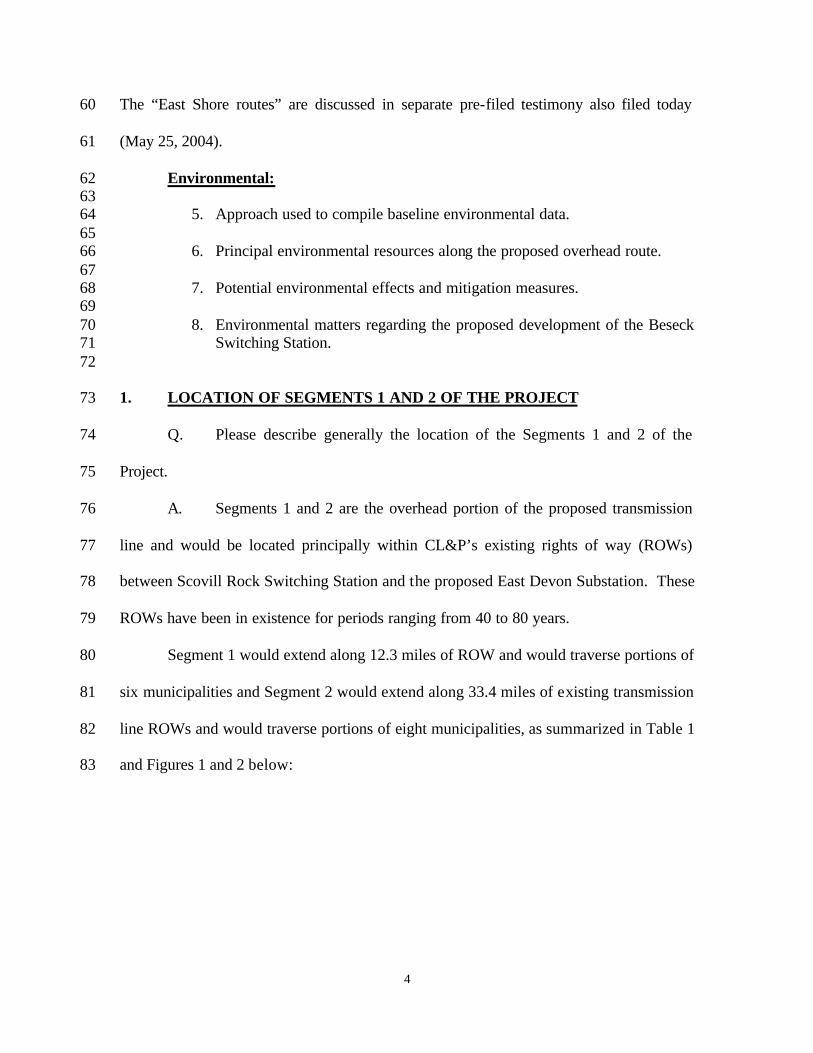
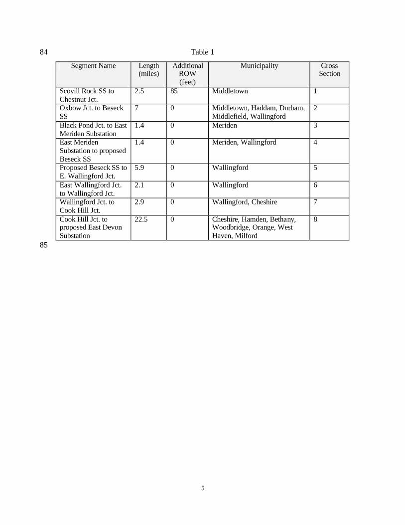
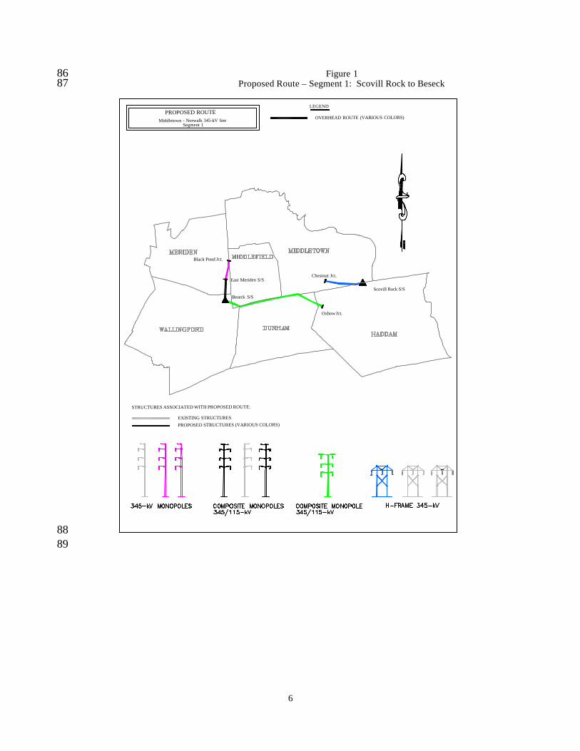
line ROWs and would traverse portions of eight municipalities, as summarized in Table 1 82
and Figures 1 and 2 below: 83
5
Table 1 84
Segment Name Length (miles)
Additional ROW (feet)
Municipality Cross Section
Scovill Rock SS to Chestnut Jct.
2.5 85 Middletown 1
Oxbow Jct. to Beseck SS
7 0 Middletown, Haddam, Durham, Middlefield, Wallingford
2
Black Pond Jct. to East Meriden Substation
1.4 0 Meriden 3
East Meriden Substation to proposed Beseck SS
1.4 0 Meriden, Wallingford 4
Proposed Beseck SS to E. Wallingford Jct.
5.9 0 Wallingford 5
East Wallingford Jct. to Wallingford Jct.
2.1 0 Wallingford 6
Wallingford Jct. to Cook Hill Jct.
2.9 0 Wallingford, Cheshire 7
Cook Hill Jct. to proposed East Devon Substation
22.5 0 Cheshire, Hamden, Bethany, Woodbridge, Orange, West Haven, Milford
8
85
6
Figure 1 86 Proposed Route – Segment 1: Scovill Rock to Beseck 87
STRUCTURES ASSOCIATED WITH PROPOSED ROUTE:
EXISTING STRUCTURES
PROPOSED STRUCTURES (VARIOUS COLORS)
East Meriden S/S
LEGEND
OVERHEAD ROUTE (VARIOUS COLORS)PROPOSED ROUTE
Middletown - Norwalk 345-kV lineSegment 1
Scovill Rock S/S
Chestnut Jct.
Oxbow Jct.
Black Pond Jct.
Beseck S/S
88 89
7
Figure 2 90 Proposed Route - Segment 2: Beseck to East Devon 91
92
Wallingford S/S
East Wallingford Jct.
Beseck S/S
Cook Hill Jct.
East Devon S/S
LEGEND
OVERHEAD ROUTE (VARIOUS COLORS)
PROPOSED ROUTEMiddletown - Norwalk 345-kV line
Segment 2
SUPPORTED CHANGE
STRUCTURES ASSOCIATED WITH PROPOSED ROUTE:
EXISTING STRUCTURES
PROPOSED STRUCTURES (VARIOUS COLORS)
93
8
94 Q. Is the Segment 1 area between Scovill Rock Switching Station and 95
Chestnut Junction the only location where additional ROW easements would have to be 96
acquired for the overhead transmission line? 97
A. Yes. Approximately 9.5 acres of new easement would have to be acquired 98
from private landowners in this area. Along the rest of the route between Scovill Rock 99
and Chestnut Junction, the additional ROW expansion would be on lands owned by 100
Northeast Utilities. 101
Q. Do the Companies support any changes to the proposed route in Segments 102
1 or 2? 103
A. Yes. The Companies have supported one change in Segment 2. This 104
change was identified during the Municipal Consultation Process for the Project and is 105
described in the Application (refer to Section I.1) and depicted on the Volume 11 Map 106
Segments (Nos. 80-83). The supported change would involve a minor modification to 107
minimize impacts to a residential subdivision in Cheshire. It would entail the removal of 108
one of the existing 115-kV overhead circuits (Circuit 1640) from the existing ROW to 109
accommodate the proposed 345-kV facilities and the remaining 115-kV line (Circuit 110
1208) on a single structure. The 115-kV line that would be removed would be rebuilt 111
underground, using cross- linked polyethylene (“XLPE”) cable. 112
Q. Where would the underground 115-kV line be located and how long 113
would it be? 114
A. The line would be approximately 4,900 feet in length, and would be 115
installed primarily within two local roads (Old Farms Road and Old Lane Road in 116
Cheshire). The beginning and end of the underground segment would be buried for short 117
9
distances within CL&P’s existing ROW. At the northern end of the supported change in 118
Cheshire, the cable would be connected to the overhead line at a location about 100 feet 119
within CL&P’s ROW; at the intersection of the ROW with Old Farm Road, the cable 120
would be aligned within the road. 121
At the southern end of the supported change, from Old Lane Road in Cheshire, 122
the cable would extend approximately 450 feet along CL&P’s existing ROW (425 feet of 123
which would be in Hamden), before reconnecting to the overhead line. 124
The supported change would eliminate the need to clear approximately 3 acres of 125
tree buffer adjacent to the residential area. 126
Q. Would the underground 115-kV XLPE cable contain any dielectric fluid? 127
A. No. The 115-kV XLPE cable would be solid dielectric. 128
Q. Would private property have to be acquired for Project modifications to 129
the Scovill Rock Switching Station or to construct the Beseck Switching Station? 130
A. No. The modifications to the Scovill Rock Switching Station would be 131
within the existing property boundaries. The Beseck Switching Station would be located 132
on approximately 5.4 acres within a 52-acre undeveloped parcel that CL&P owns in fee. 133
134
2. REVIEW OF ROUTING CRITERIA 135
Q. In your April 8, 2004, direct testimony regarding the underground portion 136
of the Project (Segments 3 and 4), you described the criteria used to evaluate routes for 137
the Project. Please review the routing criteria that were used to identify the proposed 138
route along Segments 1 and 2. 139
10
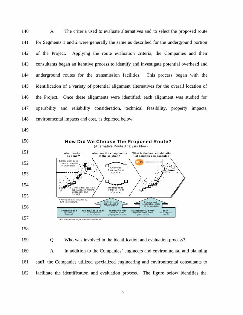
A. The criteria used to evaluate alternatives and to select the proposed route 140
for Segments 1 and 2 were generally the same as described for the underground portion 141
of the Project. Applying the route evaluation criteria, the Companies and their 142
consultants began an iterative process to identify and investigate potential overhead and 143
underground routes for the transmission facilities. This process began with the 144
identification of a variety of potential alignment alternatives for the overall location of 145
the Project. Once these alignments were identified, each alignment was studied for 146
operability and reliability consideration, technical feasibility, property impacts, 147
environmental impacts and cost, as depicted below. 148
149
150
151
152
153
154
155
156
157
158
Q. Who was involved in the identification and evaluation process? 159
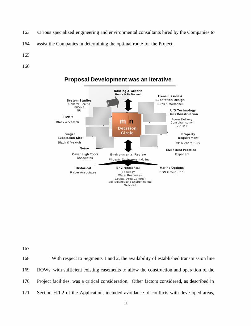
A. In addition to the Companies’ engineers and environmental and planning 160
staff, the Companies utilized specialized engineering and environmental consultants to 161
facilitate the identification and evaluation process. The figure below identifies the 162
What is the best combination of solution components?
What needs to be done?*
What are the components of the solution?
How Did We Choose The Proposed Route?
* Per regional planning led by ISO-New England.
(Alternative Route Analysis Flow)
PROPERTY IMPACTImpact on homes &
property; Visual impact
ENVIRONMENTAL IMPACTImpact on wildlife, vernal
pools, aquifers
SYSTEM BENEFITOperability†, Reliability†
TECHNICAL FEASIBILITYCan it be engineered?
Can it be built?
COSTCost to engineer
and bui ld
† Per national and regional reliability standards.
Overhead Point -to-Point
Options
Underground Point -to-Point
Options
1.Strengthen power source to a point in Wallingford
2. Connect that source to substations in Milford, Bridgeport, and Norwalk
1
1
2
22
Evaluate each option based on
these criteria
Evaluate each combination based
on these criteria
11
various specialized engineering and environmental consultants hired by the Companies to 163
assist the Companies in determining the optimal route for the Project. 164
165
166
167
With respect to Segments 1 and 2, the availability of established transmission line 168
ROWs, with sufficient existing easements to allow the construction and operation of the 169
Project facilities, was a critical consideration. Other factors considered, as described in 170
Section H.1.2 of the Application, included avoidance of conflicts with deve loped areas, 171
Routing & CriteriaBurns & McDonnell
Routing & CriteriaBurns & McDonnell
Transmission &Substation DesignBurns & McDonnell
m nDecision
Circle
m nDecision
Circle
U/G TechnologyU/G Construction
Power Delivery Consultants, Inc.
JD Hair
Property Requirement
CB Richard Ellis
EMF/ Best PracticeExponentEnvironmental Review
Phoenix Environmental, Inc.
HistoricalRaber Associates
Environmental(Topology
Water ResourcesCoastal Area Cultural)
Soil Science and Environmental Services
Marine OptionsESS Group, Inc.
General ElectricISO-NE
NU
HVDC
Black & Veatch
Singer Substation Site
Black & Veatch
Noise
Cavanaugh TocciAssociates
System Studies
Proposal Development was an Iterative ProcessProposal Development was an Iterative Process
12
consideration of visual effects, avoidance or minimization of effects to environmental 172
resources, construction feasibility constraints, and ROW accessibility for both 173
construction and maintenance purposes. 174
175
3. DISCUSSION OF THE NORTHERLY ROUTE. 176
Q. Please describe the Northerly Route. 177
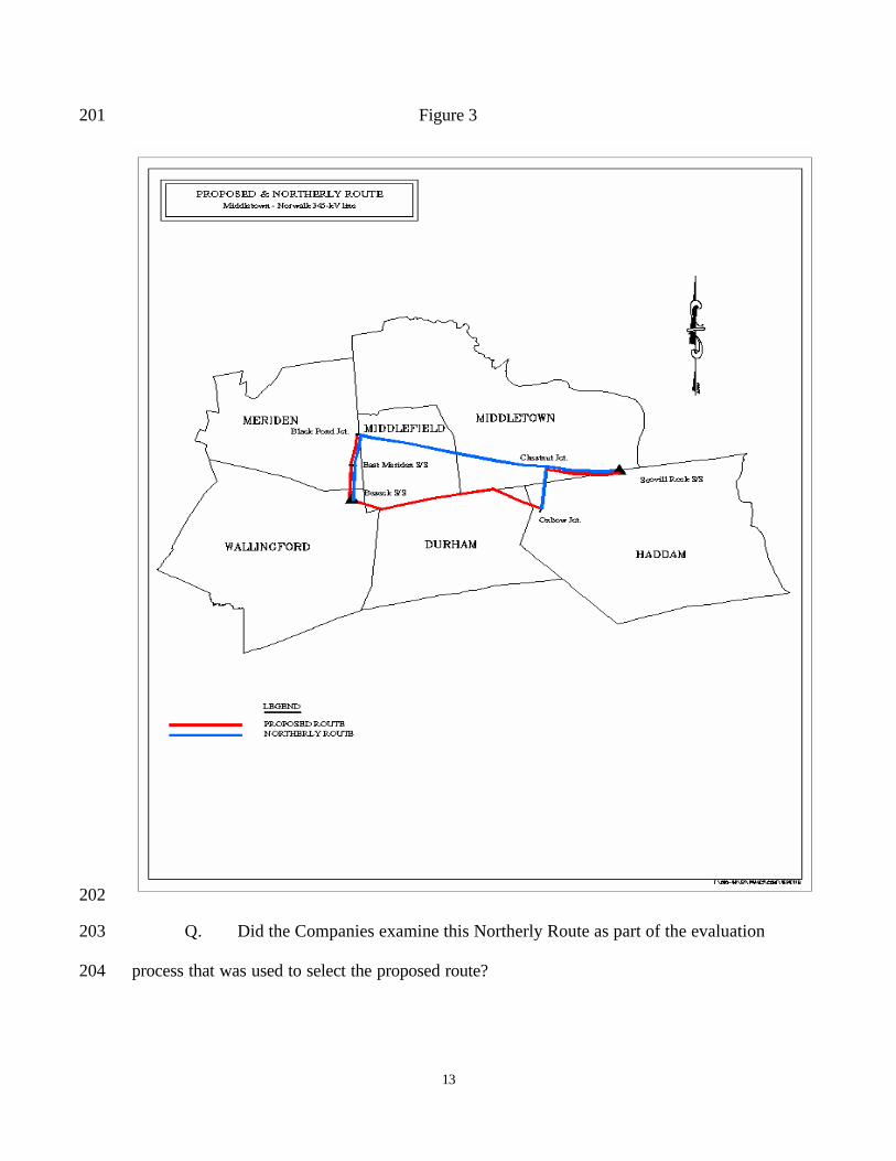
A. The Northerly Route was suggested by the Town of Durham as an 178
alternative to the use of the proposed ROW between Oxbow Junction and the proposed 179
Beseck Switching Station. With this routing option, the 345-kV line would be installed 180
along the following existing CL&P ROWs: 181
182
• Traversing west from Chestnut Junction, through Hans Brook Junction and then 183 to Black Pond Junction, the route would follow a ROW presently occupied by 184 three 345-kV transmission lines (the 387, 362, and 348 lines). From Hans Brook 185 Junction to Chestnut Junction, a 115-kV line also is located on the ROW. This 186 configuration would place four 345-kV lines on a common ROW. 187
188 • Extending south from Black Pond Junction to the proposed Beseck Switching 189
Station, the route would be aligned along the same ROW as the proposed route. 190 This ROW is presently occupied by one 345-kV transmission line (the 387 line). 191 Three additional 345-kV lines would be added to the ROW which would place 192 four 345-kV lines on a common ROW. 193
194 The Northerly Route would traverse portions of Middletown, Middlefield, Meriden, and 195
Wallingford. In comparison, the proposed route would follow existing CL&P ROWs 196
through Haddam, Durham, Middlefield, and Wallingford. Figure 3 shows the two routes. 197
198
199
200
13
Figure 3 201
202
Q. Did the Companies examine this Northerly Route as part of the evaluation 203
process that was used to select the proposed route? 204
14
A. The Companies evaluated potential routes based on system benefit, 205
technical feasibility, property impact, environmental impact, and cost. The Companies 206
eliminated this route early in the review process due to reliability concerns (system 207
benefit). This route would require approximately 11 miles of four 345-kv lines on a 208
common ROW. 209
Q. What analyses of this route did the Companies perform? 210
A. The Companies conducted a comparative analysis of the Northerly Route 211
and the portion of the proposed route that it would replace (i.e., the proposed route 212
between Oxbow Junction and the Beseck Switching Station). 213
Q. Is the proposed route preferable to the Northerly Route? 214
A. Yes. The Companies have identified system operational factors 215
(reliability issues), construction issues, and potential social impacts that make this option 216
less preferable than the proposed route. The Northerly Route would require the location 217
of four 345-kV circuits along a common ROW between Chestnut Junction and Black 218
Pond Junction, and between Black Pond Junction and the proposed Beseck Switching 219
Station, raising reliability concerns should contingencies arise. In comparison, the 220
proposed route would involve the placement of one 345-kV circuit and one 115-kV 221
circuit on a common ROW between Oxbow Junction and Beseck, where there are 222
presently no existing 345-kV lines. 223
Further, the Northerly Route would be 50% longer than the proposed route. In 224
addition, depending on structure configurations (involving trade-offs between shorter 225
structures on a wider ROW vs. taller structures on the existing ROW), the alternative 226
15
would require the expansion of the existing ROW up to 80 feet, require ROW clearing of 227
up to 62 acres and the acquisition of up to eight residences. 228
Q. What are the possible structure configurations? 229
A. With many public concerns being voiced about the aesthetic impacts of 230
overhead transmission structures, the Companies investigated expanding the existing 231
ROW and constructing the new 345-kV transmission facilities on steel H-Frame 232
structures similar in height and appearance to the wood H-Frame structures already in 233
place between Chestnut Junction and Black Pond Junction. This configuration requires 234
for the ROW to be expanded by 80 feet, would have no overall increase in the structure 235
height in the area, but would require the expansion of the ROW by approximately 62 236
acres. Much of this land is not currently owned by Northeast Utilities and would have to 237
be acquired from private, municipal, and state landowners. This is Configuration A. 238
Configuration B provides the opportunity to construct a new 345-kV transmission 239
line with less expansion of the ROW as well as preserving the existing facilities. This 240
configuration calls for constructing the new 345-kV transmission line in a vertical 241
configuration on steel monopoles typically 130 feet tall in a vertical configuration. The 242
ROW would have to be expanded by 40 feet between Chestnut Junction and Hans Brook 243
Junction; by 30 feet between Hans Brook Junction and Black Pond Junction; and by 35 244
feet between Black Pond Junction and East Meriden Substation. The total amount of 245
ROW expansion would be approximately 38 acres. Much of this property is not currently 246
owned by Northeast Utilities and would have to be acquired from private, municipal and 247
state landowners. This configuration reduces the amount of property affected; however, 248
it increases the overall structure height in the area. 249
16
The Companies examined a design configuration that would require no ROW 250
expansion. Configuration C. This design, however, calls for the complete reconstruction 251
of all of the transmission lines within the ROW from 80 foot H-frame construction to 130 252
foot steel monopoles. The complete removal of all existing structures and the erection of 253
all new structures along a longer route would triple the cost. Additionally, 18.2 circuit 254
miles of conductor will need to be replaced - further increasing the cost as compared to 255
Configurations A and B. Furthermore, the 345-kV transmission lines in this corridor 256
carry a substantial amount of power. The long-term outages necessary for the complete 257
reconstruction of all existing lines would compromise the reliability of the electric 258
system. Finally, the need to replace the capacity of the affected lines while they are out 259
of service would result in significant additional costs for electricity as the older, less 260
efficient local generation is used to supply the electricity normally carried by the affected 261
lines. 262
Any structure configurations along the Northerly Route would require higher 263
costs compared to the proposed route. The specific dollar amount of increased costs will 264
depend on the transmission line configuration and ROW requirements. The direct 265
increased cost could be as high as an incremental $47 million. Under Configuration C, 266
extended outages of all three existing 345-kV circuits would be required in order to 267
construct the Northerly Route. This would result in significant uplift charges that would 268
further increase costs. In particular, Configuration C would require several long duration 269
outages of major 345-kV transmission lines. There currently exist three 345-kV separate 270
lines within this ROW. Configuration C would call for all of them to be rebuilt on steel 271
monopoles in a vertical configuration. This would require temporary outages of these 272
17
existing transmission lines. The project schedule and the total project cost will be 273
severely affected by trying to schedule those outages if this design is utilized. As an 274
example, a recent project in this corridor to replace structures required an outage that 275
lasted four days on the 348 line between Millstone Generating Station and the 276
Southington Substation resulting in uplift costs in excess of $600,000. This type of major 277
capital expenditure seriously affects the cost of any project requiring outages of major 278
transmission lines. 279
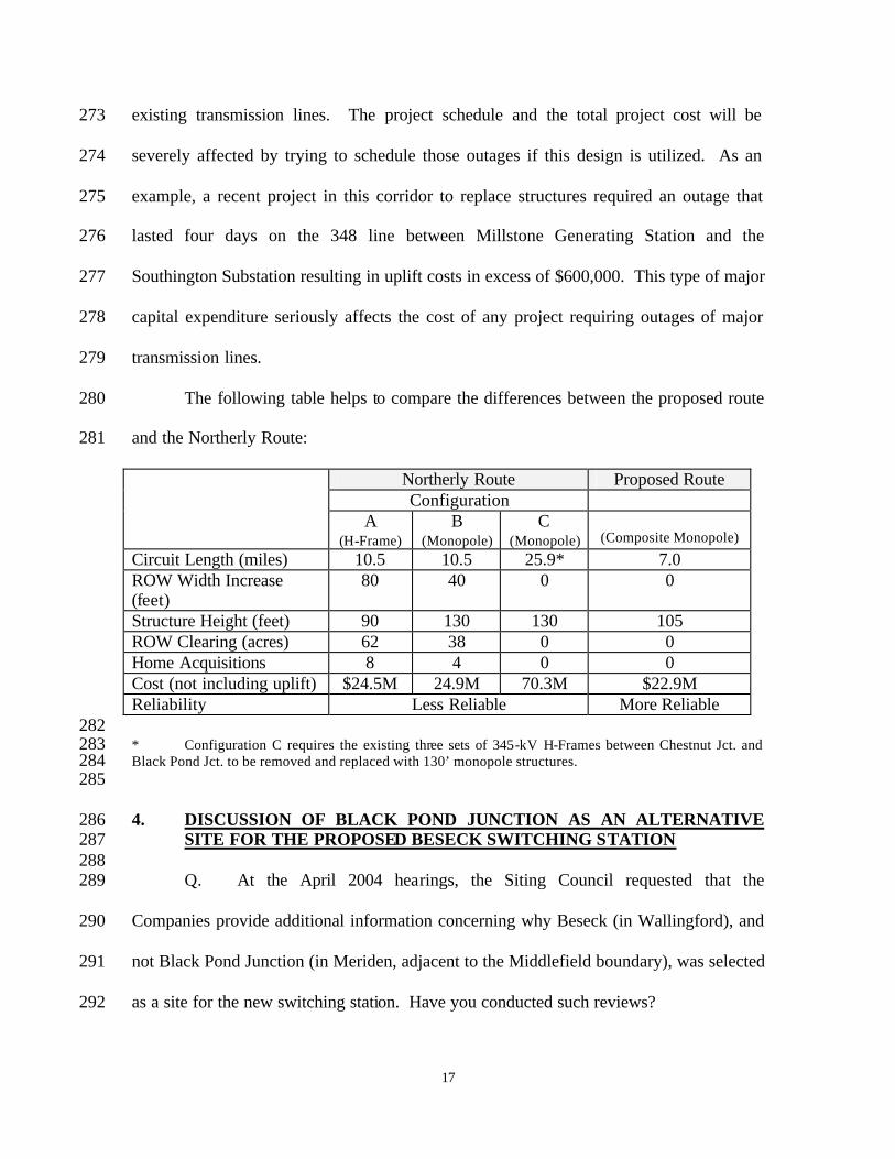
The following table helps to compare the differences between the proposed route 280
and the Northerly Route: 281
Northerly Route Proposed Route Configuration
A (H-Frame)
B (Monopole)
C (Monopole)
(Composite Monopole)
Circuit Length (miles) 10.5 10.5 25.9* 7.0 ROW Width Increase (feet)
80 40 0 0
Structure Height (feet) 90 130 130 105 ROW Clearing (acres) 62 38 0 0 Home Acquisitions 8 4 0 0 Cost (not including uplift) $24.5M 24.9M 70.3M $22.9M Reliability Less Reliable More Reliable 282 * Configuration C requires the existing three sets of 345-kV H-Frames between Chestnut Jct. and 283 Black Pond Jct. to be removed and replaced with 130’ monopole structures. 284 285
4. DISCUSSION OF BLACK POND JUNCTION AS AN ALTERNATIVE 286 SITE FOR THE PROPOSED BESECK SWITCHING STATION 287
288 Q. At the April 2004 hearings, the Siting Council requested that the 289
Companies provide additional information concerning why Beseck (in Wallingford), and 290
not Black Pond Junction (in Meriden, adjacent to the Middlefield boundary), was selected 291
as a site for the new switching station. Have you conducted such reviews? 292
18
A. Yes. The Companies selected Beseck as the preferred site for a switching 293
station because it meets the requirements for a strong source of power to serve SWCT 294
and it also meets the Companies’ site selection criteria for substations and switching 295
stations, as described in the Siting Council Application (Volume 1, Section H.6.1). 296
Q. Please elaborate on the factors that led to the selection of Beseck over 297
Black Pond Junction for the proposed switching station. 298
A. As discussed in the Siting Council Application (Volume 1, Section G.4.1), 299
the identification of the best strong source of power available for transmission to SWCT 300
was critical to the 345-kV transmission system design. Transmission system supply 301
options were evaluated from three sources outside of the SWCT region: Southington 302
Substation, Frost Bridge Substation, and the Middletown area. From among these, the 303
Middletown area was selected as the strongest source because eastern Connecticut is rich 304
in generation resources. Within the Middletown area, both Beseck and Black Pond 305
Junction are electrically equivalent and would meet the “best strong source” requirement. 306
However, the Companies prefer the Beseck site, for several reasons: 307
• Line routing: To reach Black Pond Junction, the new 345-kV line would 308
be installed along the Northerly Route. As discussed above, the 309
Companies prefer the proposed route. 310
• Land Acquisition Requirements: Because neither of the Companies owns 311
property at Black Pond Junction, land for a new switching station would 312
have to be acquired. The Beseck site is located on land that has been 313
owned by Northeast Utilities for 40 years. Only 5.4 acres of the 52 acre 314
Beseck site would be developed for the switching station. 315
19
• Terrain: Preliminary analysis suggests that extensive cut and fill 316
earthwork, including blasting, would be required to develop the site for a 317
switching station at Black Pond. The terrain at Beseck appears to be less 318
challenging. 319
• Restricted Access: Access to the Black Pond Junction site is limited by 320
Route 691 on the South and by wetlands on the East and West. 321
Accordingly, access to the site will need to come from the North, which 322
may conflict with access to the Police Academy. Ample access to the 323
Beseck site is available. 324
• Land Use: The area around Black Pond Junction is wooded and is zoned 325
for rural residential use. The Beseck site is also wooded, but is zoned for 326
industrial use. 327
• State Forest / Recreational: Black Pond Junction borders the Cockaponset 328
State Forest and is located west of and in close proximity to Mt. Higby (a 329
trap rock ridge and recreational area). The proposed switching station 330
would be visible from the Mattabassett Trail (Connecticut blue-blazed trail 331
system) located on Cockaponset State Forest property at the top of Mt. 332
Higby, and from other vista locations along the ridge top. 333
Thus, Black Pond Junction does not rate as well as Beseck under the Companies’ 334
substation / switching station site evaluation criteria (Volume 1, Section H.6.1 of the 335
Siting Council Application), including minimizing the need to acquire private lands for 336
the Project and selecting sites that are zoned for industrial use. 337
338
20
5. ENVIRONMENTAL DATA COLLECTION APPROACH 339
Q. In your April 8, 2004, direct testimony regarding the underground portion 340
of the Project (Segments 3 and 4), you described the types of data that were compiled to 341
characterize the existing environmental conditions in the Project area. Was the same 342
approach used to characterize existing environmental conditions in the overhead portion 343
of the Project area? 344
A. Yes. As discussed in Section L of the Application, the environmental data 345
compilation effort involved the collection / analysis of documents, the performance of 346
field investigations, and consultations with state, federal, and local agencies. 347
Q. Did the focus of environmental data compilation efforts differ for the 348
overhead and underground portions of the Project? 349
A. The same types of data were compiled for the Project as a whole. 350
However, because the overhead portion of the Project would involve primarily the use of 351
existing CL&P rights of way (ROW), rather than an alignment principally within public 352
road ROWs, additional effort was required to identify and characterize environmental 353
features such as biological resources, visual resources, and cultural resources. 354
Q. Please briefly describe the field studies performed for Segments 1 and 2. 355
A. Like the underground portion of the Project, field studies were performed 356
to identify and describe wetlands, watercourses, and amphibian breeding areas. Field 357
reconnaissance or studies also were conducted with respect to cultural resources, visual 358
resources, land uses, and noise. 359
Biological field surveys were performed by Soil Science and Environmental 360
Services, Inc. (“SSES”), a consulting firm that specializes in wetland and watercourse 361
21
delineations, as well as amphibian studies. Field surveys to describe and delineate 362
Connecticut regulated wetlands and watercourses were conducted in 2002 and 2003; the 363
results of these studies are summarized in the CSC Application Volume 1 (Section L.2). 364
The boundaries of Connecticut-regulated watercourses and wetlands are illustrated on the 365
Volume 9 and Volume 11 maps. A copy of the SSES Wetland and Waterways 366
Description Report is included in Volume 2 of the Application. 367
Additional wetland field studies were performed in late 2003 and in 2004. The 368
purpose of these studies was to delineate federal jurisdictional wetlands (the criteria for 369
which are slightly different than Connecticut jurisdictional wetlands), the boundaries of 370
which are needed for the Companies’ permit application to the U.S. Army Corps of 371
Engineers (“ACOE”). At the same time, SSES worked with the Companies’ personnel 372
and Burns & McDonnell to identify areas where proposed structures could be moved 373
slightly to avoid wetlands and to identify areas where wetlands or watercourses would 374
have to be crossed to provide access during construction or operation of the Project. The 375
results of these studies are discussed in more detail in Sections 4 and 5 of this testimony. 376
Amphibian breeding field studies were conducted in the spring of 2003. The 377
SSES report describing the results of these studies is presented in Volume 3 of the 378
Application. 379
Baseline noise studies were performed to characterize conditions in the vicinity of 380
the proposed Beseck Switching Station site, which is planned for location on CL&P 381
property adjacent to existing transmission line ROWs. The noise survey was performed 382
by Cavanaugh Tocci Associates, Inc. 383
22
In addition, a cultural resource study, performed by Raber Associates, was 384
completed to compile information about the history of the Project area; to identify known 385
archaeological, historic architectural, and historic engineering resources in the vicinity; 386
and to assess the potential archaeological sensitivity for discovering unrecorded sites 387
along the proposed Project route. 388
Q. Were any other specialized studies conducted of Segments 1 and 2? 389
A. Yes. In accordance with the Council’s Application Guide for Terrestrial 390
Electric Transmission Facilities (September 9, 2003, Section H.1.d), an analysis of bird 391
species that could potentially breed in the vicinity of the proposed ROW was performed 392
(refer to Volume 4 of the Application). 393
Further, the Companies conducted analyses of existing structure heights on the 394
existing CL&P ROWs and took visual resource factors into consideration in designing 395
the height of the new structures for the proposed Project (refer to Volume 1, Section 396
M.5.3 of the Application). Computer simulations were performed to portray views of the 397
proposed structures in relation to the existing landscape (including the existing 398
transmission structures) and Plan & Profiles also were developed (refer to Volumes 8 and 399
10 of the Application). 400
401
6. PRINCIPAL ENVIRONMENTAL RESOURCES ALONG THE PROPOSED 402 OVERHEAD ROUTE. 403 404
Q. What are the environmental resources that have been identified along 405
Segments 1 and 2? 406
23
A. The aerial photography based segment maps (Volumes 9 and 11 of the 407
Application) illustrate the principal vegetation types and land uses along the overhead 408
portion of the Project. Other environmental data identified on the aerial photographs or 409
in the Application are: 410
411 • Location of existing transmission line ROWs, substations, structures and 412
existing access roads; 413 414 • Vegetative community types; 415
416 • Areas of steep slopes and rock outcrops; 417 418 • Land uses; 419
420 • Municipal boundaries; 421
422 • Municipal zoning classifications; 423 424 • Wetlands; 425 426 • Watercourses and waterbodies, including streams, rivers and lakes, drainage 427
ditches and culverts; 428 429 • Floodplain boundaries as identified by the Federal Emergency Management 430
Agency; 431 432 • Public recreational, scenic, open space, and other protected areas, including 433
forests, parks, water supplies, hunting/wildlife management areas; 434 435 • Schools and community facilities; and 436
437 • Existing infrastructure, including roads, railroads, pipelines, and cable 438
crossings. 439 440
Q. Please describe the salient environmental features along the proposed 441
overhead portion of the Project. 442
A. The overhead portion of the route along existing ROWs would span 94 443
perennial and intermittent streams, including the Coginchaug River (Durham); New Dam 444
24
Pond (Meriden); Muddy River, and the Quinnipiac River (Wallingford); Mill River 445
(Hamden); West River (Bethany); Glen Dam Reservoir (Woodbridge); Indian River 446
(Orange); and Wepawaug River (Milford). The state has designated Stream Channel 447
Encroachment Lines (“SCELs”) along the Quinnipiac River. However, no Project 448
structures would be located within such SCELs. 449
The wetland field studies conducted by SSES resulted in the identification of 168 450
wetlands within the ROWs1 along the overhead portion of the Project. It should be noted 451
that 94 of these wetlands are associated with either the perennial or intermittent 452
watercourses described above. SSES’s investigations revealed that these wetlands (all of 453
which are within the existing, long-established ROWs) are generally well-vegetated and 454
dominated by shrub swamp and shallow marsh communities. In many locations, the 455
shrub-swamp and shallow marsh wetlands extend off the existing ROWs, transitioning to 456
wetlands characterized by mixed hardwood deciduous vegetation. 457
Amphibian studies, performed by SSES during the spring amphibian breeding 458
period, resulted in the identification of 10 wetlands that have high amphibian breeding 459
potential; 24 wetlands that have moderate potential for amphibian breeding; and 35 460
wetlands that have little or no potential for amphibian breeding habitat. Two of the 10 461
wetlands with high potential appear to be vernal pools; these wetlands are located in 462
Durham and Wallingford. 463
Consultations with the Connecticut Department of Environmental Protection 464
(DEP) Natural Diversity Data Base (NDDB) indicate that several state or federally 465
designated threatened or endangered species are reported in the vicinity of the overhead 466
1 Two additional small state-regulated wetlands (0.02 acre and 0.8 acre in size) are located on the proposed East Devon Substation site and would be affected by the development of this facility.
25
portion of the Project. These include the four Species of Special Concern: the wood 467
turtle (Middletown and Milford); the eastern box turtle (Middlefield); the red-shouldered 468
hawk (Woodbridge); and the blue-winged teal (Durham). In addition, the King rail, a 469
state- listed threatened species, was identified in the Durham vicinity. 470
Q. Does the overhead portion of the route cross the state-designated coastal 471
boundary? 472
A. No. 473
Q. What other environmental resources were evaluated along the proposed 474
underground route? 475
A. An ambient noise study was performed at the proposed Beseck Switching 476
Station site. The study involved ambient sound measurements at noise sensitive 477
receptors (e.g., homes) in the vicinity of the proposed switching station site, followed by 478
an estimate of sound levels projected to occur as a result of the operation of the facility. 479
The results of the study determined that existing background sound levels in the vicinity 480
of the proposed switching station are dominated by traffic noise from I-91, which is 481
located about 0.25 mile to the west. Further, this negligible equipment noise would 482
comply with both Wallingford’s noise ordinance and the DEP Noise Regulations. 483
In addition, Raber Associates identified and evaluated archaeological and historic 484
resources for the Project. The Raber studies determined that a total of 105 Native 485
American archaeological sites are known to occur within about 1 mile of the overhead 486
portion of the proposed route. Of these, only six are within 500 feet of the proposed 487
route. There are no reported historic (Euro American) archaeological sites within 600 488
feet of the overhead portion of the route. 489
26
Research also was performed to identify known significant historic structures 490
within 0.25 mile of the overhead portion of the route; the viewshed distance was selected 491
based on discussions with the State Historic Preservation Officer’s staff archaeologist. A 492
total of 14 significant above ground historic properties, including individual struc tures 493
and districts listed on or eligible for listing on the National Register of Historic Places 494
(“NRHP”) were identified. Digital topographic profiles were developed to identify areas 495
where the proposed transmission structures would be shielded from historic properties by 496
hills, forest cover, or buildings, and photographic documentation was conducted for all 497
historic architectural properties within 0.25 mile where the digital profiles indicated a 498
potential for visibility of the electric transmission facilities. 499
Q. Are there wildlife management areas (WMAs), parks, recreational, and 500
open space lands in the vicinity of Segments 1 and 2? 501
A. Yes. These areas are identified on the Volume 9 and 11 maps, and are 502
discussed in Volume 1, Sections L.3.2.2 and L.5.3. They include the Durham Meadows 503
WMA, Cockaponset State Forest, Black Pond WMA, Lyman Meadows Golf Course, 504
Sleeping Giant State Park, Naugatuck State Forest, Seven Falls Sate Park, Quinnipiac 505
River State Park, Brooksvale Recreational Area and Park, Fred P. Wolff Park, and 506
Eisenhower Park. 507
508
7. POTENTIAL ENVIRONMENTAL EFFECTS AND MITIGATION 509 MEASURES 510 511
Q. What potential environmental effects were evaluated with respect to the 512
construction and operation of the overhead portion of the Project? 513
A. The Companies considered the following potential environmental effects: 514
27
515 • Topography, geology, and soils; 516
517 • Water resources and water quality (wetlands [including vernal pools], 518
watercourses, floodplains, groundwater, and pubic water supply areas); 519 520 • Biological resources 521
• riparian and upland vegetation; 522 • wildlife (including birds); 523 • amphibians; 524 • fisheries; and 525 • threatened/endangered species. 526
527 • Land uses (including scenic and recreational resources; open space and 528
protected areas; local, state, and federal land use plans; existing and future 529 development); 530
531 • Road, railroad, and utility crossings; 532 533 • Archaeological and historic resources; and 534 535 • Air quality and noise. 536
537 Q. What potential effects would the overhead portion of the Project have on 538
topography, geology, and soil resources? 539
A. There will be negligible effects on topography, geology, and soils. All 540
activities involving soil disturbance would be performed in accordance with the 541
Companies’ best management practices and suitable soil erosion and sedimentation 542
controls would be installed, consistent with the 2002 Connecticut Guidelines for Soil 543
Erosion and Sediment Control. 544
Q. What potential effects would the overhead portion of the Project have on 545
water resources? 546
A. As described in Volume 1, Section M.2.1 of the Application, along the 547
overhead portion of the Project, structures would be located away from waterbodies 548
wherever possible and wires would span watercourses. During construction, the 549
28
Companies would adhere to specific procedures designed to minimize or avoid impacts. 550
Crossings of streams by construction equipment would be limited or avoided. Any 551
equipment crossings would be performed in accordance with the conditions of the 552
Council’s certificate and the permits from the DEP and the ACOE. Further, except along 553
existing access roads, vegetation removal along the ROW would be minimized within a 554
50-foot wide buffer around streams. This would preserve desirable vegetation for habitat, 555
shading, bank stabilization, and erosion/sedimentation control. 556
Q. What effect would the overhead portion of the Project have on wetlands? 557
A. The overhead portion of the proposed route would be within existing 558
ROWs, along which various wetlands are already spanned by existing transmission lines. 559
In some areas, existing transmission structures are located in wetlands. 560
Along the existing ROWs that the overhead portion of the Project would follow, 561
approximately 116 transmission structures are presently located in or immediately 562
adjacent to wetlands (refer to the Application, Volume 1, Table L-5). Access to all of 563
these structures exists as a result of the construction, maintenance, modification and 564
repair activities that have been performed on these transmission ROWs over the past 40 565
to 80 years. 566
The Companies would attempt to avoid the installation of structures in wetlands 567
and, where such construction cannot be avoided, would implement best management 568
practices including temporary erosion controls, surface roughening, temporary seeding, 569
and mulching to limit potential wetland impacts. Based on the structure location analyses 570
for the proposed route (refer to the Volume 9 maps) and on the wetland descriptions and 571
delineations performed by SSES, the Companies anticipate that some of the existing 572
29
structures presently located in wetlands would be removed and that fewer new structures 573
would have to be placed in wetlands. 574
In most cases, where wetlands cannot otherwise be avoided, the limited and short-575
term construction work in wetlands would consist primarily of: 576
577
• Modifications to existing access roads or establishment of new access 578 roads through certain wetlands to reach structure sites, where no upland 579 access alternatives are available; 580
581 • Activities associated with the installation of new 345-kV/115-kV 582
structures in wetlands (i.e., removal of wetland soils and vegetation in the 583 structure foundation area); and/or 584
585 • Activities associated with the removal and reconstruction of certain of the 586
existing structures that are presently located in wetlands. 587 588
When removing vegetation within 50 feet of wetlands, the Companies would 589
selectively remove trees and would maintain a brush understory in order to maintain a 590
shade canopy. 591
Q. Subsequent to the submission of the Application to the Council, have the 592
Companies conducted any additional studies to minimize impacts to wetlands? 593
A. Yes. The Companies have conducted additional field studies and worked 594
with Project engineers and Burns & McDonnell to make preliminary technically feasible 595
design adjustments in order to locate proposed structures in upland areas, thereby 596
minimizing potential impacts to wetlands, where possible. As a result of this effort, 597
approximately 28 structures that were identified as within wetlands on the Application 598
maps (Volumes 9 and 11) would be moved so as to be placed outside of regulated 599
wetland boundaries. 600
30
Q. Have the Companies quantified the potential impacts to wetlands as a 601
result of the Project construction and operation? 602
A. Yes. Along Segments 1 and 2, the Companies estimate that approximately 603
5 acres of state-regulated wetlands would be temporarily affected during construction as a 604
result of the need for access through wetlands or for the placement of temporary work 605
pads in wetlands in order to install new structures or remove existing structures. An 606
additional 3 acres of wetlands would be permanently affected by the placement of 607
structure foundations in wetlands that could not otherwise be avoided, and the 608
development of access road extensions (that must be in wetlands in select areas) to reach 609
new structures. After the completion of construction work in a wetland, any temporary 610
work pads or temporary access would be removed and the wetland would be restored. 611
Thus, after the completion of construction, the 5 acres of temporarily affected wetlands 612
would retain wetland functions and values. The 3 acres of wetlands within which new 613
structures or access roads must be placed would be converted to non-wetland uses. 614
Q. What effect would the Project have on the two vernal pools identified 615
along the existing ROW? 616
A. The project would have no direct impact on these vernal pools. Structures 617
have been located to avoid both of these areas. Construction near these areas would be 618
timed so as not to interfere with amphibian breeding periods or other mitigation measures 619
would be implemented, as appropriate based on consultation with the DEP and the Siting 620
Council. 621
Q. Will the construction and operation of the overhead portion of the Project 622
result in adverse impacts to vegetation or wildlife resources? 623
31
A. Because Segments 1 and 2 would be along existing ROWs, effects on 624
vegetation and wildlife resources would be minimized. Some vegetation would have to 625
be removed to safely accommodate construction and operation of the transmission 626
facilities. However, the vegetation types found along the route are common in the region 627
and vegetation removal would represent a negligible overall impact on wildlife habitats 628
and populations. 629
The creation of additional shrubland habitat (and the preservation of such existing 630
habitat) along the maintained ROWs would represent a long-term positive effect because 631
shrubland habitat (like any other early successional habitat) is otherwise declining in New 632
England as a result of various factors (e.g., development, ecological succession, absence 633
of fire). In Connecticut, transmission line ROWs are considered a major source of 634
shrubland habitat. 635
The Project would result in the disturbance of a maximum of approximately 98 636
acres of primarily forested vegetation, which would be converted to shrubland habitat. In 637
areas where forest lands presently exist, the conversion to shrubland would represent a 638
long-term, but not an adverse, effect. 639
Q. Would the overhead portion of the Project affect amphibians or amphibian 640
habitat or species listed by the federal or state governments as threatened, endangered or 641
of concern? 642
A. To the extent possible, new structures would be located outside of 643
wetlands that provide high or moderate potential for productive amphibian breeding. 644
However, because several of the potential breeding areas are large wetlands that presently 645
32
contain a number of structures; it might not be possible to avoid such areas entirely. As a 646
result, some new structures would have to be placed in such wetlands. 647
To minimize adverse effects on amphibians, the Companies would schedule 648
construction activities in and near the amphibian breeding areas to avoid impacts during 649
critical periods in these species’ life cycles. The Companies would consult with the DEP 650
to identify appropriate time periods during which construction could be performed so as 651
to minimize such effects. 652
Q. Would the overhead portion of the Project affect species listed by the 653
federal or state governments as threatened, endangered or of concern? 654
A. Potential effects on the listed species of turtles and birds identified in the 655
vicinity of the overhead portion of the Project are primarily temporary and would be 656
avoided by restricting construction activities in the vicinity of the species known habitats. 657
To avoid critical periods in these species’ lifecycles, the DEP has recommended that 658
construction in the vicinity of the species’ reported habitats be conducted in accordance 659
with specified schedules. The Siting Council Application, Volume 1, Section M, Table 660
M-4 (DEP-Recommended Construction Windows for Threatened, Endangered and 661
Special Species of Concern) identifies the timing restrictions that have been 662
recommended by DEP to date. 663
The Companies expect to continue to consult with the involved resource agencies 664
during the certification and permitting phases of the Project and to assess the need, if any, 665
for further field studies to document the presence/absence of these species in the Project 666
area. The Companies anticipate that issues regarding potential threatened or endangered 667
33
species in the Project vicinity may be addressed by avoiding construction during critical 668
periods in these species’ lifecycles. 669
Q. Have you reviewed local, state, and federal land use plans, particularly 670
with respect to existing and future development, for the areas along the overhead portion 671
of the Project? 672
A. Yes. 673
Q. Will the proposed overhead portion of the Project be consistent with the 674
land uses and policies presented in these plans? 675
A. Yes. The proposed Project transmission facilities would be installed 676
within existing, long-established electric transmission ROWs, which have been dedicated 677
to utility use for 40 to 80 years. 678
Q. What effects would the overhead portion of the Project have on visual 679
resources? 680
A. Given public concerns regarding the visibility of overhead transmission 681
structures, the Companies have attempted to minimize the height of the proposed 682
structures to the extent possible. For example, from Cook Hill Junction to East Devon 683
the companies have proposed the use of 345-kV compact delta structures and have 684
designed the structures with the shield wires placed on the side of the structures and have 685
increased the tension of the conductors. This design allows the structures to be only 85 686
feet high. Without these design features, the structures would be at least 105 feet high. 687
Further, the Companies have sought to lessen the impact of the new structures on visual 688
resources because the proposed Project would be aligned entirely along existing corridors 689
(where transmission lines have been established for 40 to 80 years) and because – for the 690
34
most part – the new structures are expected to be in the same general locations as the 691
existing structures. 692
The long-term effect on visual resources in any particular area also would depend 693
on various factors, such as: 694
695
• The appearance (type and height) of the transmission structures that 696 presently occupy the ROW; 697
698 • The appearance (type and height) of the transmission structures proposed 699
for the ROW; 700 701 • The extent to which vegetation presently screens the ROW and existing 702
structures from view; 703 704 • The amount of vegetation clearing that would be required to accommodate 705
the new 345-kV facilities (and in certain areas, the rebuilt 115-kV 706 facilities); 707
708 • The extent to which topographic conditions limit views of the ROW; 709 710 • The land uses adjacent to and near the ROW; and 711 712 • Individual public perceptions concerning views of the transmission line 713
ROW and structures. 714 715
• Removal of many existing structures. 716 717
Q. What effect will the construction and operation of the overhead Project 718
have on transportation and traffic patterns? 719
A. The construction of Segments 1 and 2 would result in limited and 720
localized effects on transportation patterns, whereas the operation of the Project would 721
have no effect. 722
The well-established public road network in the Project area would afford ready 723
access to most work sites for construction vehicles and equipment. During the 724
35
construction period, construction workers traveling to work sites, as well as the 725
movement of construction equipment, may cause temporary localized increases in traffic 726
volumes on local roads near the proposed route. The Companies would employ police 727
personnel to direct traffic at construction work sites along roads, as needed, and would 728
erect appropriate traffic signs to indicate the presence of construction work zones. 729
The ROW access roads that are present along the existing transmission lines are 730
expected to be used for most construction activities. These existing access roads are 731
depicted in the aerial photographs in Volume 9, and are identified in Volume 1, Table K-732
1. The overhead portion of the Project also would cross various roads, railroads, and 733
pipelines. All such crossings would be overhead and would result in no adverse effects. 734
735
8. ENVIRONMENTAL MATTERS REGARDING THE BESECK 736
SWITCHING STATION 737
Q. What environmental effects would occur as a result of the development of 738
the Beseck Switching Station? 739
A. The Beseck Switching Station is proposed for location on a 5.4-acre 740
portion of a 52-acre undeveloped, forested property that is owned by CL&P in 741
Wallingford. The 5.4-acre site would be cleared of vegetation, and then graded and filled 742
to create a level area for the switching station facilities. The site is located at the junction 743
of existing transmission ROW, and is within an industrially zoned area. The station 744
would be consistent with the existing industrial use designation and would be compatible 745
with the other industrial uses located to the west and south. 746
The operation of the Beseck Switching Station would result in a long-term change 747
in the land use of the site, creating long-term but minor changes to topography, soils, 748
36
vegetation and wildlife, visual resources, and noise. However, these changes would be 749
localized. 750
Q. Would the development of the switching station affect water resources? 751
A. No. The construction of the proposed Beseck Switching Station, which is 752
not located within any 100-year floodplain boundary, would not directly affect any water 753
resources or wetlands. Although a wetland is located east and down-slope of the 754
proposed site, adjacent to the existing transmission line, appropriate temporary erosion 755
and sedimentation controls would be installed around disturbed areas within the station. 756
Similarly, although the site is within a large area designated by Wallingford for 757
watershed protection, neither the construction nor the operation of the switching station is 758
expected to affect Wallingford’s watershed protection area. Appropriate spill prevention, 759
control and countermeasure procedures would be implemented during the construction 760
and during operation of the facility. 761
Q. How would the development of the switching station affect visual 762
resources? 763
A. The construction and operation of the station would alter the visual 764
characteristics of the site, resulting in a long-term change. However, this development 765
would be consistent with the property’s industrial zoning, as well as with the character of 766
the facilities in the industrial park along Carpenter Road and Technology Drive. Further, 767
the Companies have mitigated the potential adverse visual impacts associated with views 768
of the switching station from nearby residential areas by proposing to locate the station 769
on the west side of the existing CL&P transmission corridor, thereby separating the 770
station site from the residential areas by approximately 600 - 1,000 feet. The property 771
37
between the existing transmission corridor and High Hill Road is owned by CL&P and 772
consists of undeveloped mature forestland, which would serve as a visual screen. The 773
Companies would plant additional vegetative screening around the station. 774
Q. Does this conclude your testimony? 775
A. Yes. 776
777
778
\10705\1209\468116.3 779
780
781