WIFI Alarm Control Panel User Manual · message for the users.It is very safe and easy. Remote...
44
P/N:20161208B01 WIFI Alarm Control Panel User Manual Ver:1.0
Transcript of WIFI Alarm Control Panel User Manual · message for the users.It is very safe and easy. Remote...
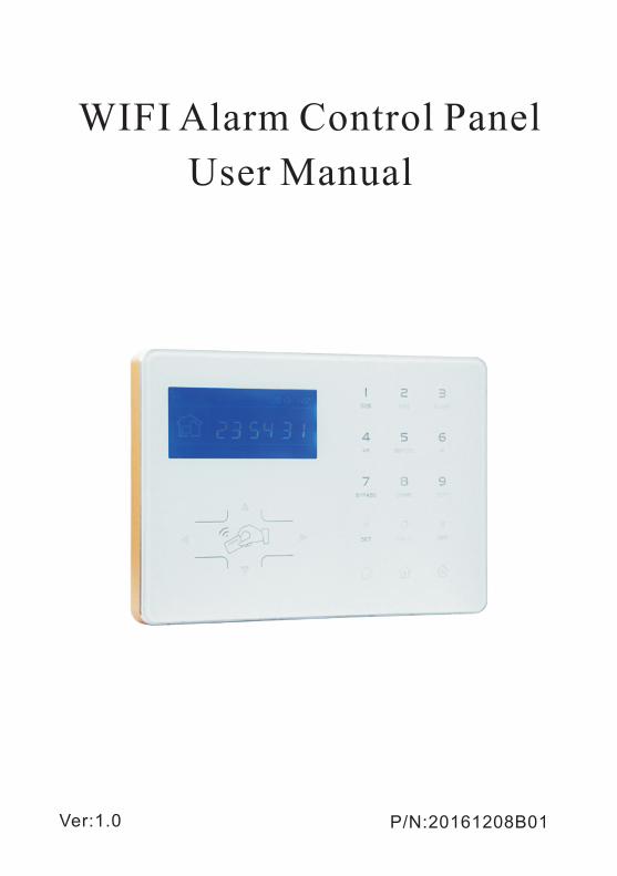
P/N:20161208B01
WIFI Alarm Control Panel
User Manual
Ver:1.0

Brief Thank you for purchasing the “smart home”products of our
company,thank you again,we hope our products can bring
convenience and protection for your safety!
The”smart home” system uses the most advanced digital
sensing and control technology,it is a set of smart alarm
control system of anti-theft,anti-fire, and anti-gas leak. The
use of dual-core CPU makes the product more efficient for
operation, energy-efficient and longer life. "Smart home"
products connect mobile phone APP and platform through
wireless WIFI and adopt wireless alarm way to push the
message for the users.It is very safe and easy. Remote
control can be achieved at any time to grasp the surrounding
environment news. It is the best choice of modern security
alarm products for users.This product is easy to operate
and easy to learn with voice indication all around the
operation,complicated orders are not needed.
The “smart home” system recommends the most advanced
multirandom vault technology in safety and reliability,which
effectively solves the problem of interference ,false positives,
false negatives that cannot be solved by similar system at
present.”Smart home” system supports international and
universal SIA-2013 of Internet GPRS, and Contact ID Protocol
of GSM,which makes application of this series of products
wider and compatibility stronger.The system can be widely
used in family,community,villas,shops,units and so on.
We recommend that you carefully read the instruction to
facilitate you for a skilled operation and use to the product,so
the product can better serve for you.
We will not notice if there is a change of product performance,
if you want to know the latest features,please contact with the
relevant business.
User manual
User manual
Chapter I Introduction
Chapter II Installation and Connection
2.1 Installation
2.2 Phone card inserted
2.3 Install wireless detector
Chapter III Key Description and Basic Operation
3.1 Key description
3.2 Basic operation
3.3 LCD Icon
3.4 System arm and disarm
3.5 Alarm procedure
Chapter IV Voice Alarm Receiving and GSM control
4.1 Remote phone control
4.2 Alarm receiving phone operation
4.3 GSM remote operation
4.4 GSM alarm receiving
4.5 GSM control via SMS
Chapter V System Settings
5.1 Set password
5.1.1 Set admin password
5.1.2 Set user password
5.2 Set CMS
5.3 Set voice phone
5.4 Set system options
5.4.1 Set system clock
5.4.2 Set entry delay
5.4.3 Set exit delay
5.4.4 Set detector loss inspection
5.4.5 Set arm/disarm tone
5.4.6 Set AC off delay
5.4.7 Set force arm
5.4.8 Set magnetic contact inspection
Content
1
4
4
4
4
5
5
6
7
8
9
10
10
10
11
11
11
12
12
13
13
13
14
15
15
16
16
16
17
17
17
18
User manual
5.4.9 Set emergency alarm siren type
5.5 Manage wireless device
5.5.1 Enroll wirless device
5.5.1.1 Enroll wireless remote controll
5.5.1.2 Enroll wireless detector
5.5.1.3 Enroll wirless siren
5.5.2 Delete wireless device
5.5.2.1 Delete wireless remote controll
5.5.2.2 Delete wireless detector
5.5.2.3 Delete wireless siren
5.5.3 Enroll RFID
5.5.4 Delete RFID
5.6 Set zone
5.6.1 Set zone attribution
5.6.2 Set related zone
5.7 System maintenance
5.7.1 Set timing arm/disarm
5.7.2 Recording
5.7.3 Play recording
5.7.4 Delete system events
5.7.5 Restore to factory default
5.8 Advanced setting options
Chapter VI APP Setting
6.1 Install APP
6.2 Set WIFI
6.3 Log in APP
6.3.1 Create local IP account
6.3.2 Other ways to create account
Chapter VII Set Web IE Interface
7.1 Host status
7.2 WIFI hotspot
7.2.1 Add hotspot
7.2.2 Delete WIFI hotspot
7.3 Log connection in WEB IE
18
18
18
19
19
20
20
21
21
21
21
22
22
23
23
24
24
25
25
25
25
26
27
27
27
28
28
29
31
31
32
32
32
32
User manual
33
33
33
34
34
34
34
35
35
35
36
37
37
7.4 IP configuration
7.4.1 Site mode IP configuration
7.4.2 Hotspot mode IP configuration
7.5 Set Host CMS
7.5.1 Set Network CMS Platform
7.5.2 Set mobile control platform
7.5.3 Set Telephone Alarm Receiving Center
7.5.4 Set Personal voice phone
7.5.5 Set email
7.5.6 Set GPRS APN
Chapter VIII Technical specification
Chapter IX Maintenance
Chapter X Limitation of the products

1
1. Alarm mode:with Internet Network and GSM Network alarm,GSM
Network with GPRS function,remote arm and disarm panel through
CMS or SMS. CID protocol and SMS notification.
2. With a new large-screen,full-touch buttons,LCD graphic display
steps,work status,Alarm process and intuitive.
3. The full English voice prompting operation: all local or remote
operation,alarm information,event log view.
4. GSM-hook and voice telephone with intercom function.
5. All alarm information can be programmed by 16 ways.Please refer
to page26.
6. Enable enroll total 8 wireless remote,32 wireless intelligent
switches,2 wireless two way siren,unlimited for quantities of one
way wireless siren,and 16 RFID tags.
7. Alarm panel under idle status is equivalent to a cellphone,you can
call through the GSM network for balance inquiries.
8. The associated zone: 8 groups of associated zones, which can
effectively reduce false alarm or for other functions.
9. Sleep mode: Under sleep mode,all the lights,backlight,voice and
remind tone are disabled.
10. Remote phone operation:dialing by telephone offsite,after password
verification,you can arm,disarm,listen-in premise,system status
query and electrical switches controls and other operations.
11. Voice alarm: When panel alarm,it will automatically dial the preset
user phone numbers to report alarm information.
12. 64 wireless zones,each wireless zone can automatically learn the
codes or be coded manually via the keyboard.
13. 1 CMS platform, support many devices to log in,while network
monitoring.
14. Follow me phone#,two for CMS,four for private alarm receiving.
15. Status inspection function: Enable record and inquiry 512 alarm
event messages.Like the time when happens anti-tam per alarm,
Chapter I Product Introduction
User manual
2
User manual
detector alarm,tel-line off,arm,disarm,system setting,battery low
voltage etc. And also can inquiry the zone number and alarm type.
16. Timing arm and disarm: 4 sets of timing arm and disarm time.
17. Electrical switches control: User can remote switch on/off via
SMS or APP.
18. Zone programmable: factory preset for each zone type.Users can
modify all the zone type according to the actual needs.
19. Panel has the memory function of time power-off, but must be
registered in the GSM network to set the correct time for the panel,
can also be manually set by the mobile phone APP.
20. Password access management: the panel has 1 administrator
password and 16 user passwords.The administrator password
primarily for system administrators to set up the alarm system;
The user passwords for users in the day-to-day use such arm/
disarm,remote operation.The administrator password,user
password can be freely modified.
21. For CMS networking alarm,depending on the number of users,the
user can set four user codes(account number).
22. Zone type identification: After an alarm is triggered,the alarm zone
number displayed on the LCD screen of the panel,also can send the
detailed report to CMS , which includes alarm locations and zone
types.
23. Alarm mode options: stand-alone for single-family use by the
ordinary phone alarm; can also be connected with the CMS.CMS
and the ordinary phone alarm automatically with identification and
compatibility.
24. CMS communication test: The panel will send a message to CMS
at the preset time interval to inspect the communication if normal.
25. Siren options: Built-in siren,external wired siren,wireless siren.All
sirens can be programmed as enabled/disabled when alarms.
3
26. The voice speaker volume adjustment: total 8 level, adjust the
volume by a panel arrow keys.
27. Wireless repeater function: can extend the distance between the
detector and the panel by adding a wireless repeater of our company.
28. The wireless detector low battery prompted: Detectors will send
status report to the panel every 1-3 hours,the corresponding zone
number and the battery voltage symbol will be displayed on the LCD
screen and also will report to CMS.
User manual
4
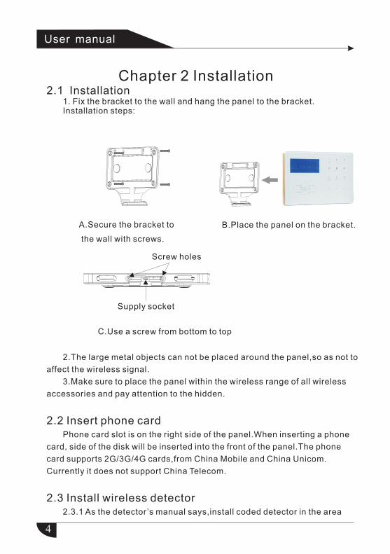
A.Secure the bracket to
the wall with screws.
C.Use a screw from bottom to top
Screw holes
Supply socket
B.Place the panel on the bracket.
2.1 Installation 1. Fix the bracket to the wall and hang the panel to the bracket. Installation steps:
Chapter 2 Installation
User manual
2.The large metal objects can not be placed around the panel,so as not to
affect the wireless signal.
3.Make sure to place the panel within the wireless range of all wireless
accessories and pay attention to the hidden.
2.2 Insert phone cardPhone card slot is on the right side of the panel.When inserting a phone
card, side of the disk will be inserted into the front of the panel.The phone
card supports 2G/3G/4G cards,from China Mobile and China Unicom.
Currently it does not support China Telecom.
2.3 Install wireless detector 2.3.1 As the detector’s manual says,install coded detector in the area
5
#
150m from the control panel.Please test and make sure detector can work
with control panel normally.
2.3.2 Wireless repeater function: when wireless detector is too far from
the panel or some occluders between panel and detector which disable the
panel recerve the signal from wireless detector.Now you can choose our
made wireless repeater to achieve wireless signal relay transmitting.
User manual
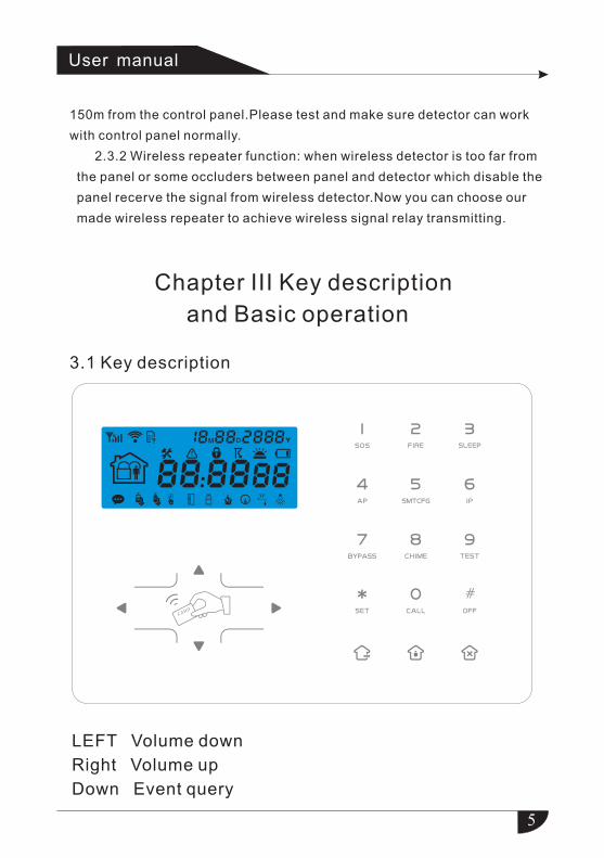
Chapter III Key description
and Basic operation
3.1 Key description
LEFT Volume down
Right Volume up
Down Event query
6
*
#
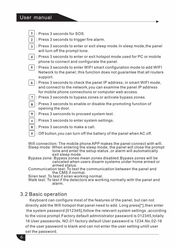
: Press 3 seconds to enter or exit sleep mode.In sleep mode,the panel
will turn off the prompt tone.
User manual
Wifi connection: The mobile phone APP makes the panel connect with wifi.Sleep mode: When entering the sleep mode, the panel will close the prompt tone and enter the setup status ,or alarm will automatically exit sleep mode.Bypass zone: Bypass zones mean zones disabled.Bypass zones will be canceled when users disarm systems under home armed or armed status.Communication test: To test the communication between the panel and the CMS if normal.Siren test: To test if siren working normal.Walk test: To test if the detectors are working normally with the panel and alarm.
: Press 3 seconds for SOS.
: Press 3 seconds to trigger fire alarm.
: Press 3 seconds to enter or exit hotspot mode used for PC or mobile
phone to connect and configurate the panel.
: Press 3 seconds to enter WIFI smart configuration mode to add WIFI
Network to the panel; this function does not guarantee that all routers
support.
: Press 3 seconds to check the panel IP address, in smart WIFI mode,
and connect to the network,you can examine the panel IP address
for mobile phone connections or computer web access.
: Press 3 seconds to bypass zones or activate bypass zones.
: Press 3 senconds to proceed system test.
: Press 3 seconds to enter system settings.
: Press 3 seconds to make a call.
: Off button,you can turn off the battery of the panel when AC off.
: Press 3 seconds to enable or disable the promoting function of opening the door.
3.2 Basic operation Keyboard can configure most of the features of the panel, but can not
directly add the Wifi hotspot that panel need to add. Long press[*],then enter
the system password [012345],follow the relevant system settings ,according
to the voice prompt.Factory default administrator password is 012345,totally
16 User passwords, NO.01 factory default User password is 1234.No.02-16
of the user password is blank and can not enter the user setting untill user
set the password.
7
Disarm: User password[1234]+DISARM Home arm: Home arm key Arm: Arm key Event log: inquiry key
User manual
Enter system setting: press and hold for more than 3 seconds+
administrator password[012345]+
Enter user setting: press and hold for more than 3 seconds+
user NO.(01)+user password(1234)+
#
#
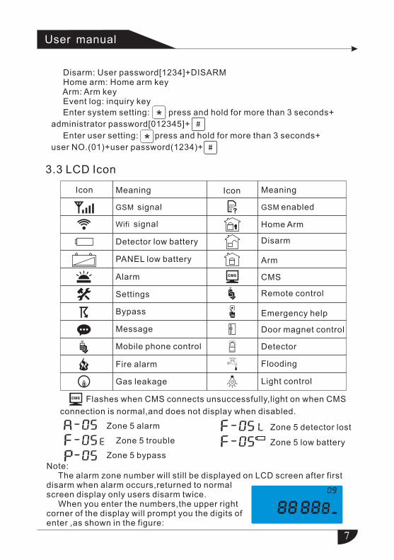
3.3 LCD Icon
Icon Meaning
Detector low battery
PANEL low battery
Alarm
Icon Meaning
+ _
GSM signal
Wifi signal
Settings
Bypass
Message
Mobile phone control
Remote control
Emergency help
Door magnet control
Detector
Flooding
Light control
Fire alarm
Gas leakage
GSM enabled
Home Arm
Disarm
Arm
CMS
Flashes when CMS connects unsuccessfully,light on when CMS
connection is normal,and does not display when disabled.
Zone 5 detector lost
Zone 5 low battery
Zone 5 alarm
Zone 5 trouble
Zone 5 bypass
Note: The alarm zone number will still be displayed on LCD screen after first disarm when alarm occurs,returned to normal screen display only users disarm twice.
When you enter the numbers,the upper right corner of the display will prompt you the digits of enter ,as shown in the figure:
1
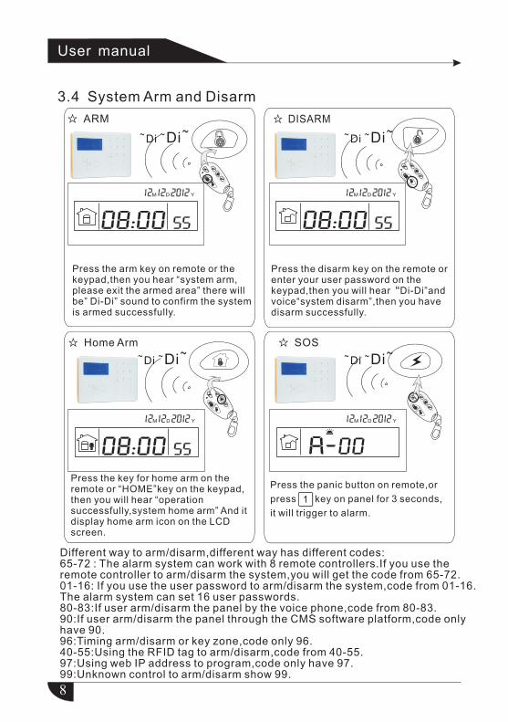
3.4 System Arm and Disarm
☆ ARM
~ ~ ~Di Di
☆ DISARM
☆ SOS☆ Home Arm
YDM YDM
YDM YDM
8
~ ~ ~Di Di
~ ~ ~Di Di~ ~ ~Di Di
Press the arm key on remote or the keypad,then you hear “system arm,please exit the armed area” there will be” Di-Di” sound to confirm the system is armed successfully.
Press the disarm key on the remote or enter your user password on the keypad,then you will hear“Di-Di”and voice system disarm”,then you have disarm successfully.
“
Different way to arm/disarm,different way has different codes:65-72 : The alarm system can work with 8 remote controllers.If you use the remote controller to arm/disarm the system,you will get the code from 65-72.01-16: If you use the user password to arm/disarm the system,code from 01-16.The alarm system can set 16 user passwords.80-83:If user arm/disarm the panel by the voice phone,code from 80-83.90:If user arm/disarm the panel through the CMS software platform,code only have 90.96:Timing arm/disarm or key zone,code only 96.40-55:Using the RFID tag to arm/disarm,code from 40-55.97:Using web IP address to program,code only have 97.99:Unknown control to arm/disarm show 99.
Press the key for home arm on theremote or “HOME”key on the keypad,then you will hear “operation successfully,system home arm” And it display home arm icon on the LCD screen.
Press the panic button on remote,or
press key on panel for 3 seconds,
it will trigger to alarm.
User manual
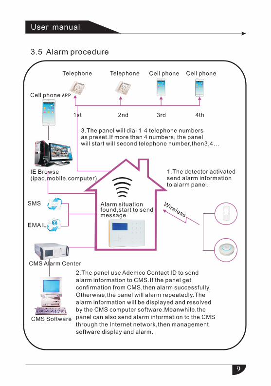
3.5 Alarm procedure
9
Telephone
1st 2nd 3rd 4th
Wireless
Cell phone Cell phone
CMS Software
IE Browse(ipad,mobile,computer)
SMS
Cell phone APP
CMS Alarm Center
User manual
Telephone
2.The panel use Ademco Contact ID to send
alarm information to CMS.If the panel get
confirmation from CMS,then alarm successfully.
Otherwise,the panel will alarm repeatedly.The
alarm information will be displayed and resolved
by the CMS computer software.Meanwhile,the
panel can also send alarm information to the CMS
through the Internet network,then management
software display and alarm.
3.The panel will dial 1-4 telephone numbers as preset.If more than 4 numbers, the panel will start will second telephone number,then3,4…
1.The detector activated send alarm information to alarm panel.
Alarm situation found,start to send message
Dial the GSM No. of the alarm control panel.
The panel will off-hook automatically.
Then enter user password according to voice prompting(the factory default user password is 1234)
1 11 1
The panel will dial the preset voice phone number when alarm occurs
10
Chapter IV Voice alarm receiving and GSM control
The user pick up the call
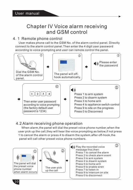
4.1
Remote phone controlUser makes phone call to the GSM No. of the alarm control panel. Directly
connect to the alarm control panel.Then enter the 4 digit user password
according to voice prompting and user can remote control the panel.
User manual
Please enter the password
4.2 Alarm receiving phone operation When alarm,the panel will dial the preset voice phone number,when the
user pick up the call,they will hear the voice prompting as below,if not press
1 to cancel the alarm or press 4 to disarm the system,after off-hook,the
panel will call other preset voice phone numbers.
Press 1 to arm systemPress 2 to disarm systemPress 3 to home arm Press 4 to appliance switch controlPress 9 to site on the progressPress 0 to Disconnect
Play the recorded voice message first,then:Press 1 to cancel the alarmPress 2 to check alarm eventPress 3 to arm systemPress 4 to disarm systemPress 5 to home armPress 6 to enable sirenPress 7 to listen-inPress 9 to intercom on sitePress 0 to disconnect
11
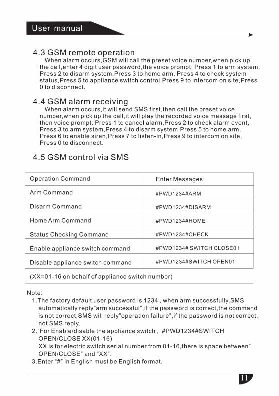
Operation Command Enter Messages
Arm Command
Disarm Command
Home Arm Command
Status Checking Command
Enable appliance switch command
Disable appliance switch command
(XX=01-16 on behalf of appliance switch number)
#PWD1234#ARM
#PWD1234#DISARM
#PWD1234#HOME
#PWD1234#CHECK
#PWD1234# SWITCH CLOSE01
#PWD1234#SWITCH OPEN01
User manual
4.3 GSM remote operation When alarm occurs,GSM will call the preset voice number,when pick up the call,enter 4 digit user password,the voice prompt: Press 1 to arm system,
Press 2 to disarm system,Press 3 to home arm, Press 4 to check system status,Press 5 to appliance switch control,Press 9 to intercom on site,Press 0 to disconnect.
4.4 GSM alarm receiving When alarm occurs,it will send SMS first,then call the preset voice
number,when pick up the call,it will play the recorded voice message first,then voice prompt: Press 1 to cancel alarm,Press 2 to check alarm event,Press 3 to arm system,Press 4 to disarm system,Press 5 to home arm,Press 6 to enable siren,Press 7 to listen-in,Press 9 to intercom on site,Press 0 to disconnect.
4.5 GSM control via SMS
Note:
1.The factory default user password is 1234 , when arm successfully,SMS
automatically reply”arm successful”,if the password is correct,the command
is not correct,SMS will reply”operation failure”,if the password is not correct,
not SMS reply.
2.“For Enable/disable the appliance switch , #PWD1234#SWITCH
OPEN/CLOSE XX(01-16)
XX is for electric switch serial number from 01-16,there is space between”
OPEN/CLOSE” and “XX”.
3.Enter “#” in English must be English format.
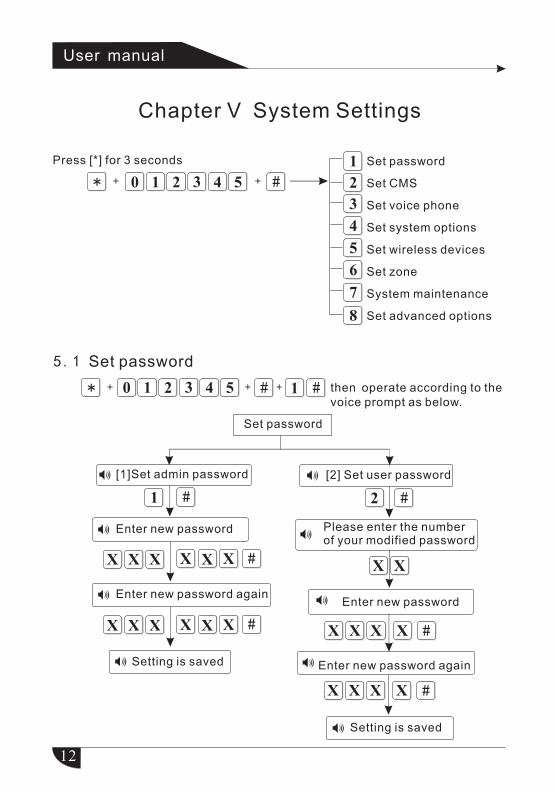
Chapter V System Settings
12
* + #+
Set password
Set CMS
Set voice phone
Set system options
Set wireless devices
Set zone
System maintenance
Set advanced options
Press [*] for 3 seconds
5.1 Set password
2 ##
#
* #+ + + 1 # then operate according to the voice prompt as below.
#
#
#
X X X X X X
X X X X X X
X X
X X X X
X X X X
User manual
Set password
[1]Set admin password
Enter new password
Enter new password again
Setting is saved
[2] Set user password
Please enter the number of your modified password
Enter new password
Enter new password again
Setting is saved
13
1 6 ++ #
* # 1 2# #
#
+ + + +
+
+ 000 1
321 40 5
#++ 000 1
#* #+ + +
* # #
#
+ + +
++
321 40 5
#++
#+
User manual
Press [*] for 3 seconds
Enter password
Enter new passwordEnter new pass-word again
Setting is saved
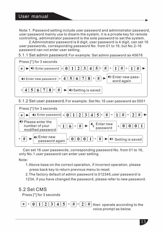
Note:1. Password setting include user password and administrator password, user password mainly use to disarm the system, it is a private key for remote controlling, administrator password is the sole password to set the system. 2.Administrator password is 6 digit, user password is 4 digit, can set 16 user passwords, corresponding password No. from 01 to 16, but No.2-16 password can not enter user setting.
5.1.1 Set admin password.For example: Set admin password as 45678
5.1.2 Set user password.For example: Set No.16 user password as 0001
Press [*] for 3 seconds
Enter password
Setting is savedEnter new password again
Please enter the number of your modified password
Enter new password
Can set 16 user passwords, corresponding password No. from 01 to 16, only No.1 user password can enter user setting.
Note:
1.Above base on the correct operation, if incorrect operation, please
press back key to return previous menu to reset.
2.The factory default of admin password is 012345,user password is
1234, if you have changed the password, please refer to new password.
5.2 Set CMSPress [*] for 3 seconds
then operate according to the voice prompt as below.
14
# # # # #
XX #X
#* #+ + +
XX #X XX #X XX #X
#
User manual
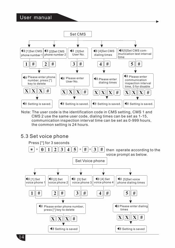
then operate according to the voice prompt as below.
Set CMS
[1]Set CMS
phone number 1
[2]Set CMS phone number 2
[3]Set User No.
[4]Set CMS
dialing times
[5]Set CMS com-munication test interval time
Please enter phone number, press [*] key to delete
Please enter User No.
Please enter dialing times
Please enter communication inspection interval time, 0 for disable
Setting is saved. Setting is saved. Setting is saved. Setting is saved.
Note: The user code is the identification code in CMS setting, CMS 1 and CMS 2 use the same user code, dialing times can be set as 1-15,
communication inspection interval time can be set as 0-999 hours, the common setting is 24 hours.
5.3 Set voice phone Press [*] for 3 seconds
Set Voice phone
[1] Set voice phone 1
[2] Set voice phone 2
[3] Set voice phone 3
[4] Set voice phone 4
[5]Set voice phone dialing times
Please enter phone number, press [*] key to delete
Please enter dialing times
Setting is saved Setting is saved
15
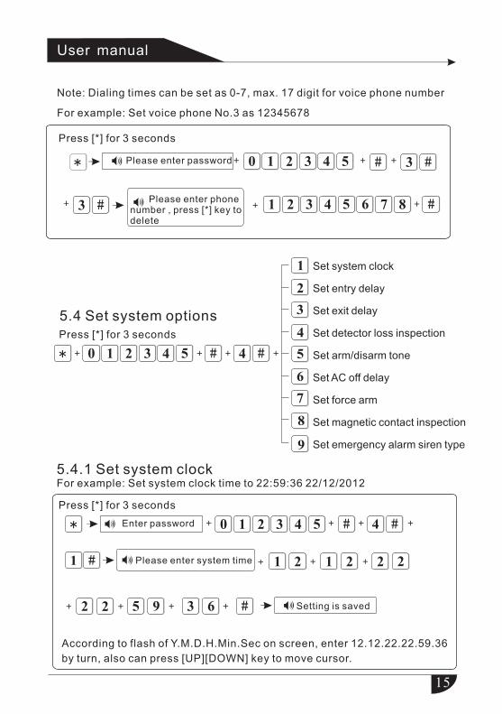
Note: Dialing times can be set as 0-7, max. 17 digit for voice phone number
For example: Set voice phone No.3 as 12345678
* # #+ + +
#+ + #+
* ##+ + +
5.4.1 Set system clockFor example: Set system clock time to 22:59:36 22/12/2012
* # #
#
#
+ + +
+ +
+
+
+
3210 54
User manual
Set system clock
Set entry delay
Set exit delay
Set detector loss inspection
Set arm/disarm tone
Set AC off delay
Set force arm
Set magnetic contact inspection
Set emergency alarm siren type
Press [*] for 3 seconds
Please enter password
Please enter phone number , press [*] key to delete
5.4 Set system optionsPress [*] for 3 seconds
Enter password
Please enter system time
Setting is saved
According to flash of Y.M.D.H.Min.Sec on screen, enter 12.12.22.22.59.36
by turn, also can press [UP][DOWN] key to move cursor.
Press [*] for 3 seconds
16
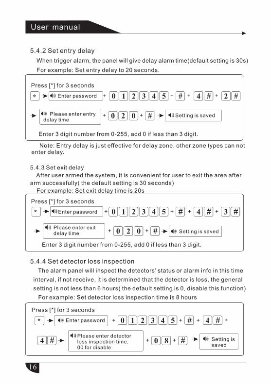
5.4.2 Set entry delay
When trigger alarm, the panel will give delay alarm time(default setting is 30s)
For example: Set entry delay to 20 seconds.
Note: Entry delay is just effective for delay zone, other zone types can not enter delay.
5.4.3 Set exit delay
After user armed the system, it is convenient for user to exit the area after
arm successfully( the default setting is 30 seconds)
For example: Set exit delay time is 20s
5.4.4 Set detector loss inspection
The alarm panel will inspect the detectors’ status or alarm info in this time
interval, if not receive, it is determined that the detector is loss, the general
setting is not less than 6 hours( the default setting is 0, disable this function)
For example: Set detector loss inspection time is 8 hours
*
Press [*] for 3 seconds
# 4 # 2 #
Please enter entry delay time
0
3210 54
2 0 + #
Enter 3 digit number from 0-255, add 0 if less than 3 digit.
Enter password + ++ +
+ Setting is saved
* # 4 # 3 #
Please enter exit delay time 0
3210 54
2 0 + #
Enter 3 digit number from 0-255, add 0 if less than 3 digit.
+ ++ +
+
# 4 #
4 #
3210 54
0 8 + #
*
+
+ + + +
Press [*] for 3 seconds
Please enter detector loss inspection time, 00 for disable
Press [*] for 3 seconds
Enter password
Setting is saved
Enter password
Setting is saved
User manual
17
# 4 #
5 #Please choose1. Disable 2. Short sound
3210 54
2 + #
Press [*] for 3 seconds
Enter password*
+
+ + ++
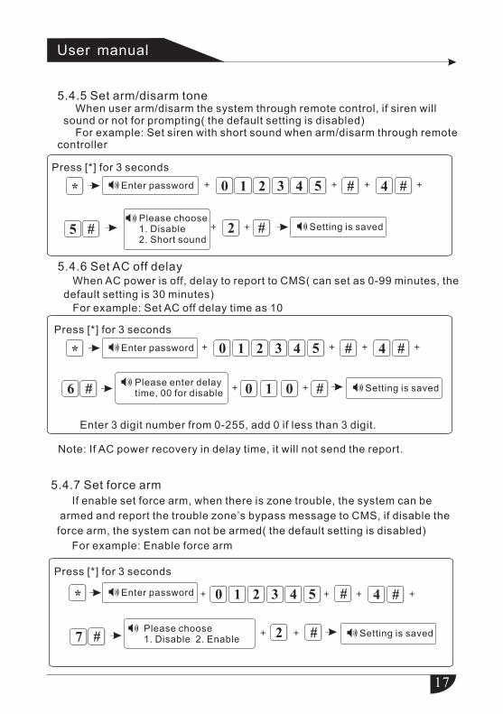
5.4.6 Set AC off delay When AC power is off, delay to report to CMS( can set as 0-99 minutes, the
default setting is 30 minutes)
For example: Set AC off delay time as 10
# 4 #
6 #Please enter delaytime, 00 for disable
3210 54
0 + #
Press [*] for 3 seconds
Enter password*
+
+ + ++
Enter 3 digit number from 0-255, add 0 if less than 3 digit.
0 1
5.4.7 Set force arm
If enable set force arm, when there is zone trouble, the system can be
armed and report the trouble zone’s bypass message to CMS, if disable the
force arm, the system can not be armed( the default setting is disabled)
For example: Enable force arm
# 4 #
7 # 2 #
3210 54* + + + +
+ +
Note: If AC power recovery in delay time, it will not send the report.
5.4.5 Set arm/disarm tone When user arm/disarm the system through remote control, if siren will sound or not for prompting( the default setting is disabled) For example: Set siren with short sound when arm/disarm through remote controller
Setting is saved
User manual
Setting is saved
Please choose 1. Disable 2. Enable
Press [*] for 3 seconds
Enter password
Setting is saved

18
5.4.8 Magnetic contact inspection: Set if the alarm panel show zone trouble on LCD screen or not when separate the magnetic strip from transmitter( factory default: disable) For example: Set enable/disable magnetic contact inspection
# 4 #
8 # 1 #Please choose: 1.disable 2.enable magnetic contact inspection
3210 54
Press[*] for 3 seconds
Enter password* + + +
+ +
+
# 4 #
9 # 2Please choose:1.Mute 2.pedal point
310 542 + +* +
+
+
+ #
5.4.9 Set emergency alarm siren type(default: mute) For example: Set emergency alarm siren type to pedal point
5.5 Manage wireless device
* # 5 #3210 54
1
2
4
+ ++
5.5.1 Enroll wireless device
* # 5 #3210 54
1
2
3
1 #+ + ++
3
Enroll remote controller
Enroll wireless detector
Enroll wireless siren
Setting is saved
Press[*] for 3 seconds
Enter password
Setting is saved
User manual
Press[*] for 3 seconds Enroll wireless device
Delete wireless device
Enroll RFID
Delete RFID
Press[*] for 3 seconds
19
1 #
#
+ +
+
# 5 # 1 #3210 54
Press [*] for 3 seconds
Enter password* + + + +
211 11 13
41 #+LCD screen display the code of this remote control
1 #
Add successfully, please press confirm key to add the next device, press back to exit
#
+
+
# 5 # 1 #3210 54
Press [*] for 3 seconds
Enter password* + + + +
#+LCD screen display the code of this remote control
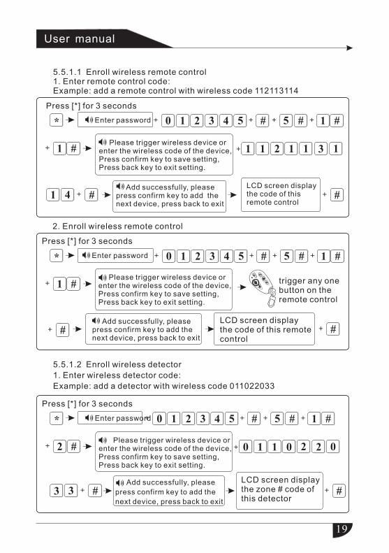
2. Enroll wireless remote control
trigger any one button on the remote control
Please trigger wireless device or enter the wireless code of the device, Press confirm key to save setting,Press back key to exit setting.
Add successfully, please press confirm key to add the next device, press back to exit
5.5.1.1 Enroll wireless remote control1. Enter remote control code:Example: add a remote control with wireless code 112113114
User manual
Please trigger wireless device or enter the wireless code of the device, Press confirm key to save setting,Press back key to exit setting.
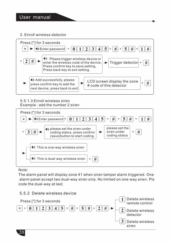
5.5.1.2 Enroll wireless detector
1. Enter wireless detector code:
Example: add a detector with wireless code 011022033
2 #
#
+ +
+
# 5 # 1 #3210 54
Press [*] for 3 seconds
Enter password* + + + +
110 20 02
33 #+
LCD screen display the zone # code of this detector
Please trigger wireless device or enter the wireless code of the device, Press confirm key to save setting,Press back key to exit setting.
Add successfully, please
press confirm key to add the
next device, press back to exit
20
2 #
#
+
+
# 5 # 1 #3210 54* + + + +
#+
LCD screen display the zone # code of this detector
Trigger detector
Note:
The alarm panel will display zone 41 when siren tamper alarm triggered. One
alarm panel accept two dual-way siren only. No limited on one-way siren. Pls
code the dual-way at last.
# 5 # 1 #
please set the siren under coding status, press confirm (save)button to start coding.
3210 54
3 #please set the siren under coding status
#
#
* + + + +
+ +
+
This is one-way wireless siren
This is dual-way wireless siren
5.5.2 Delete wireless device
* # 5 #3210 54
1
2
3
Delete wireless detector
2 #+ + ++
2. Enroll wireless detector
User manual
Press [*] for 3 seconds
Enter password
Please trigger wireless device or enter the wireless code of the device, Press confirm key to save setting,Press back key to exit setting.
Add successfully, please
press confirm key to add the
next device, press back to exit
5.5.1.3 Enroll wireless sirenExample : add the number 2 siren
Press [*] for 3 seconds
Enter password
Press [*] for 3 secondsDelete wireless remote control
Delete wireless siren
21
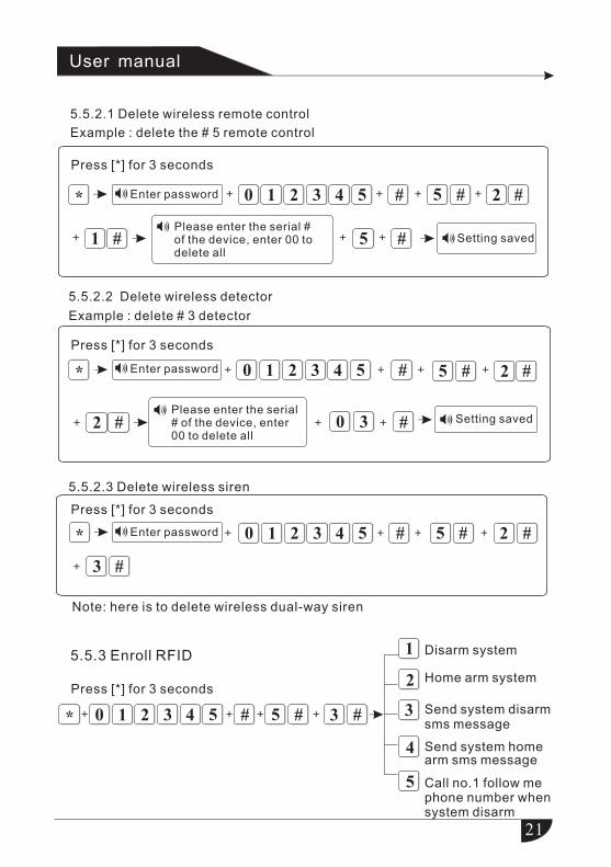
5.5.2.1 Delete wireless remote control
Example : delete the # 5 remote control
# 5 # 2 #
#Please enter the serial # of the device, enter 00 to delete all
3210 54
1 # 5
*
+ +
+ + + +
+ Setting saved
5.5.2.2 Delete wireless detector
Example : delete # 3 detector
# 5 # 2 #3210 54
2 # 0 3 #
* + + +
+ + +
+
# 5 # 2 #3210 54
3 #
Note: here is to delete wireless dual-way siren
* + + + +
+
Please enter the serial # of the device, enter 00 to delete all
5.5.3 Enroll RFID
* # 5 #3210 54
1
2
3 #+ ++ +
Disarm system
Home arm system
3
4
5
User manual
Press [*] for 3 seconds
Enter password
Press [*] for 3 seconds
Enter password
Setting saved
5.5.2.3 Delete wireless siren
Press [*] for 3 seconds
Enter password
Press [*] for 3 seconds
Call no.1 follow me phone number when system disarm
Send system disarm sms message
Send system home arm sms message
22
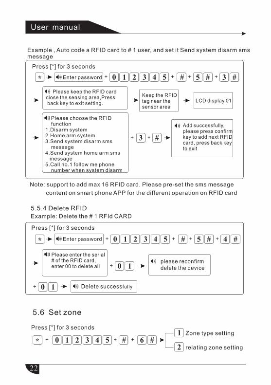
Example , Auto code a RFID card to # 1 user, and set it Send system disarm sms message
# 5 # 3 #3210 54
#
Please keep the RFID card close the sensing area,Press back key to exit setting.
3
* ++ + +
+ +
Note: support to add max 16 RFID card. Please pre-set the sms message
content on smart phone APP for the different operation on RFID card
Add successfully, please press confirm key to add next RFID card, press back keyto exit
Keep the RFID tag near the sensor area
LCD display 01
5.5.4 Delete RFID
Example: Delete the # 1 RFId CARD
# 5 # 4 #3210 54
Please enter the serial # of the RFID card, enter 00 to delete all
please reconfirm delete the device
* ++ + +
Delete successfully
10+
10+
* # 6 #3210 541
2
Zone type setting
relating zone setting
++ +
5.6 Set zone
User manual
Press [*] for 3 seconds
Enter password
Please choose the RFID function1.Disarm system2.Home arm system3.Send system disarm sms message4.Send system home arm sms message5.Call no.1 follow me phone number when system disarm
Enter password
Press [*] for 3 seconds
Press [*] for 3 seconds
23
5.6.1 Set zone attribution
1.Zone attribution is the alarm type of the zone display on the alarm panel’
s LCD screen when the zone is triggered. When set the zone attribution as
0 is to disable the zone. The alarm panel will not make alarm when trigger
this zone.
2.interior zone only trigger alarm when the zone is triggered under system at
armed status.
3.delay and perimeter zone trigger alarm when the zone is triggered under
system at armed or home arm status.
4.emergency zone, 24 hours zone, fire zone will trigger alarm when system
at any status.
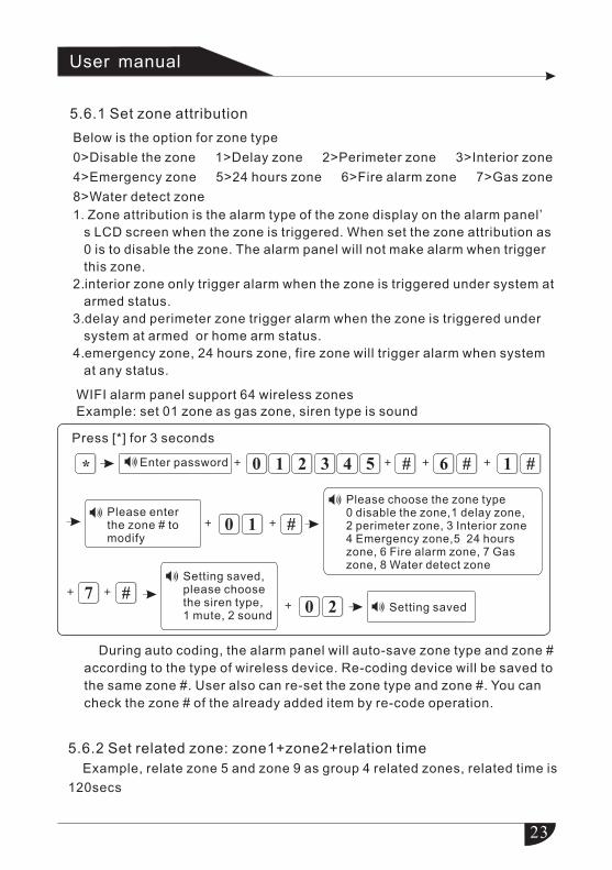
WIFI alarm panel support 64 wireless zones
Example: set 01 zone as gas zone, siren type is sound
# 6 # 1 #3210 54
Please enter the zone # to modify
0 #1
Please choose the zone type0 disable the zone,1 delay zone, 2 perimeter zone, 3 Interior zone4 Emergency zone,5 24 hours zone, 6 Fire alarm zone, 7 Gas zone, 8 Water detect zone
* + + +
+ +
+
7 #+ +
Setting saved, please choosethe siren type, 1 mute, 2 sound
Setting saved
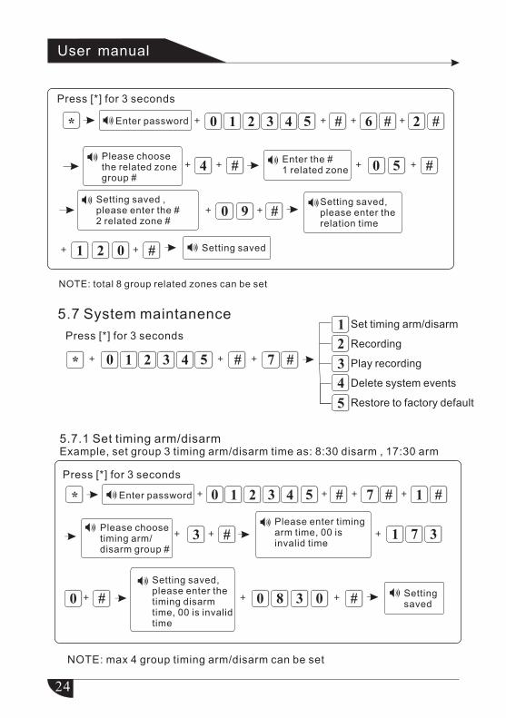
5.6.2 Set related zone: zone1+zone2+relation time
Example, relate zone 5 and zone 9 as group 4 related zones, related time is
120secs
During auto coding, the alarm panel will auto-save zone type and zone #
according to the type of wireless device. Re-coding device will be saved to
the same zone #. User also can re-set the zone type and zone #. You can
check the zone # of the already added item by re-code operation.
0 2+
User manual
Below is the option for zone type
0>Disable the zone 1>Delay zone 2>Perimeter zone 3>Interior zone
4>Emergency zone 5>24 hours zone 6>Fire alarm zone 7>Gas zone
8>Water detect zone
Press [*] for 3 seconds
Enter password
24
# 6 # 2 #3210 54
#Please choose the related zone group #
4 #Enter the # 1 related zone 5
Setting saved ,please enter the # 2 related zone #
#0
NOTE: total 8 group related zones can be set
* + + +
+ +
+ +
+
0 +
9Setting saved, please enter the relation time
#2+ +0 Setting saved1
+
# 7 # 1 #3210 54
Please enter timing arm time, 00 is invalid time
1
#
7
Setting saved,please enter the timing disarm time, 00 is invalid time
0
* + + +
+
+ +
+
3
0 8 3 0 #
Please choose timing arm/disarm group #
#+3+
+
NOTE: max 4 group timing arm/disarm can be set
5.7 System maintanence
Press [*] for 3 seconds
* # 7 #3210 54
1
2
3
4
5
+ ++
Setting saved
User manual
Press [*] for 3 seconds
Press [*] for 3 seconds
Enter password
Enter password
Set timing arm/disarm
Recording
Play recording
Delete system events
Restore to factory default
5.7.1 Set timing arm/disarmExample, set group 3 timing arm/disarm time as: 8:30 disarm , 17:30 arm
25
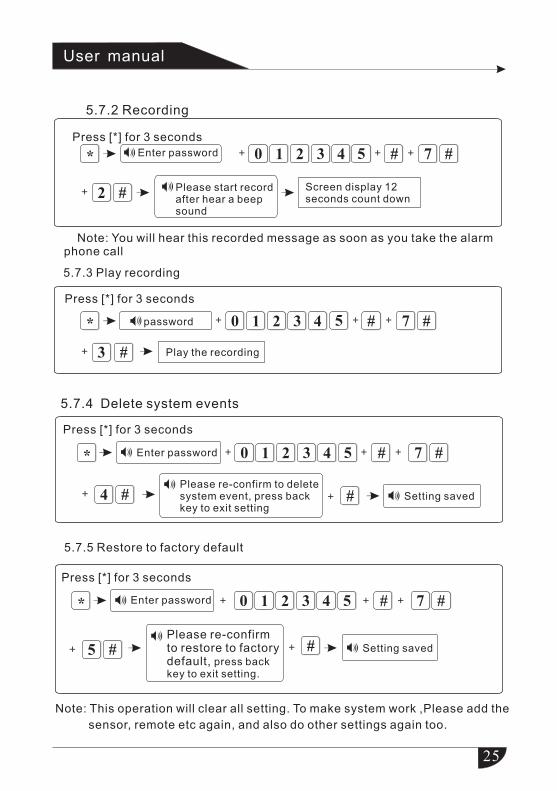
5.7.2 Recording
5.7.3 Play recording
# 7 #
2 #
3210 54* + +
+
+
Please start record after hear a beep sound
Note: You will hear this recorded message as soon as you take the alarm phone call
# 7 #
3 #
3210 54
Press [*] for 3 seconds
password* + +
+
+
Play the recording
Screen display 12 seconds count down
Note: This operation will clear all setting. To make system work ,Please add the
sensor, remote etc again, and also do other settings again too.
*
Press [*] for 3 seconds
# 7 #
4 #
3210 54
Please re-confirm to delete system event, press back key to exit setting
#
Enter password + +
+
+
+
5.7.5 Restore to factory default
*
Press [*] for 3 seconds
# 7 #
5 #
3210 54
Please re-confirm to restore to factory default, press back key to exit setting.
#
Enter password +
+
+ +
+
5.7.4 Delete system events
Setting saved
Setting saved
User manual
Enter password
Press [*] for 3 seconds
26
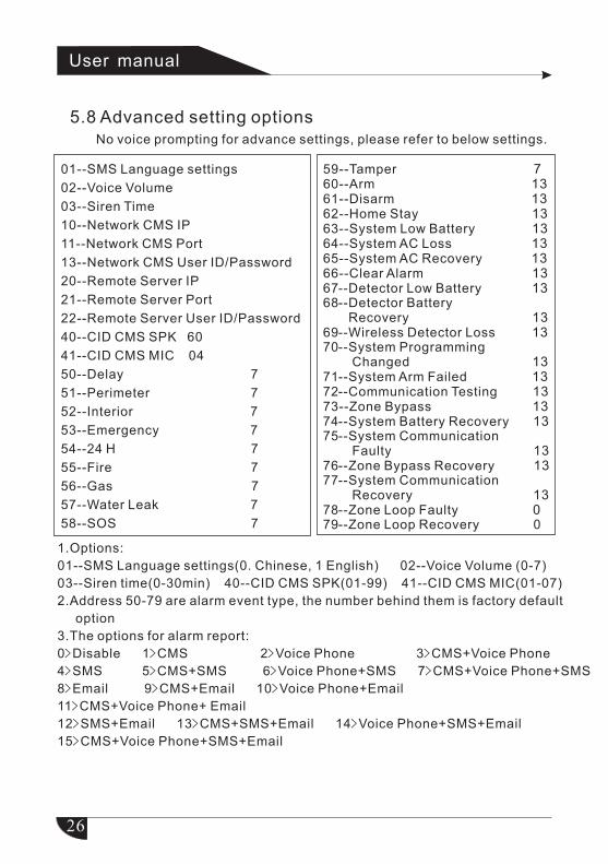
5.8 Advanced setting optionsNo voice prompting for advance settings, please refer to below settings.
User manual
01--SMS Language settings
02--Voice Volume
03--Siren Time
10--Network CMS IP
11--Network CMS Port
13--Network CMS User ID/Password
20--Remote Server IP
21--Remote Server Port
22--Remote Server User ID/Password
40--CID CMS SPK 60
41--CID CMS MIC 04
50--Delay
51--Perimeter
52--Interior
53--Emergency
54--24 H
55--Fire
56--Gas
57--Water Leak
58--SOS
7
7
7
7
7
7
7
7
7
59--Tamper 7 60--Arm 1361--Disarm 13 62--Home Stay 1363--System Low Battery 1364--System AC Loss 1365--System AC Recovery 1366--Clear Alarm 1367--Detector Low Battery 1368--Detector Battery Recovery 1369--Wireless Detector Loss 1370--System Programming Changed 1371--System Arm Failed 1372--Communication Testing 1373--Zone Bypass 1374--System Battery Recovery 1375--System Communication Faulty 1376--Zone Bypass Recovery 1377--System Communication Recovery 1378--Zone Loop Faulty 079--Zone Loop Recovery 0
1.Options:
01--SMS Language settings(0. Chinese, 1 English) 02--Voice Volume (0-7)
03--Siren time(0-30min) 40--CID CMS SPK(01-99) 41--CID CMS MIC(01-07)
2.Address 50-79 are alarm event type, the number behind them is factory default
option
3.The options for alarm report:
0>Disable 1>CMS 2>Voice Phone 3>CMS+Voice Phone
4>SMS 5>CMS+SMS 6>Voice Phone+SMS 7>CMS+Voice Phone+SMS
8>Email 9>CMS+Email 10>Voice Phone+Email
11>CMS+Voice Phone+ Email
12>SMS+Email 13>CMS+SMS+Email 14>Voice Phone+SMS+Email
15>CMS+Voice Phone+SMS+Email
27
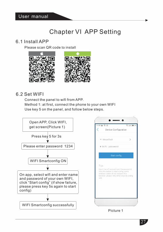
Chapter VI APP Setting
6.1 Install APP Please scan QR code to install
Press key 5 for 3s
Please enter password 1234
WIFI Smartconfig ON
On app, select wifi and enter name and password of your own WIFI, click “Start config” (if show failure, please press key 5s again to start config)
WIFI Smartconfig successfully
Open APP, Click WIFI,
get screen(Picture 1)
User manual
6.2 Set WIFI Connect the panel to wifi from APP.
Method 1: at first, connect the phone to your own WIFI
Use key 5 on the panel, and follow below steps.
Picture 1
28
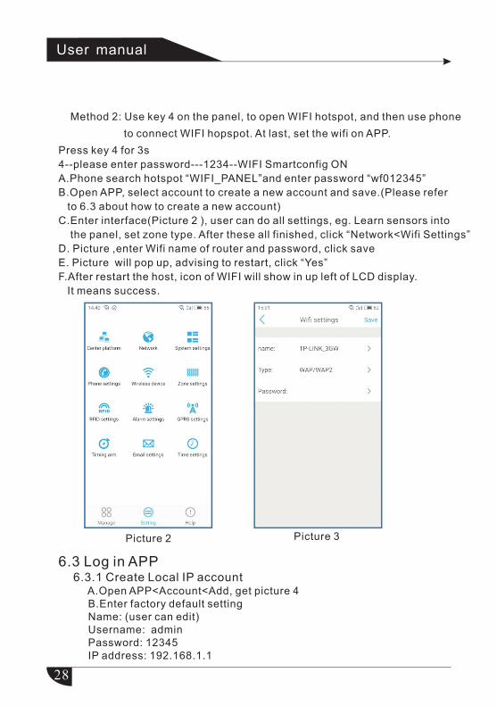
Method 2: Use key 4 on the panel, to open WIFI hotspot, and then use phone
to connect WIFI hopspot. At last, set the wifi on APP.
User manual
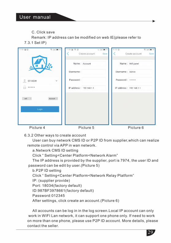
6.3 Log in APP 6.3.1 Create Local IP account
A.Open APP<Account<Add, get picture 4B.Enter factory default settingName: (user can edit)Username: adminPassword: 12345IP address: 192.168.1.1
Press key 4 for 3s
4--please enter password---1234--WIFI Smartconfig ON
A.Phone search hotspot “WIFI_PANEL”and enter password “wf012345”
B.Open APP, select account to create a new account and save.(Please refer
to 6.3 about how to create a new account)
C.Enter interface(Picture 2 ), user can do all settings, eg. Learn sensors into
the panel, set zone type. After these all finished, click “Network<Wifi Settings”
D. Picture ,enter Wifi name of router and password, click save
E. Picture will pop up, advising to restart, click “Yes”
F.After restart the host, icon of WIFI will show in up left of LCD display.
It means success.
Picture 2 Picture 3
29
C. Click save
Remark: IP address can be modified on web IE(please refer to
7.3.1 Set IP)
User manual
6.3.2 Other ways to create account
User can buy network CMS ID or P2P ID from supplier,which can realize
remote control via APP in wan network.
a.Network CMS ID setting
Click “ Setting<Center Platform<Network Alarm”
The IP address is provided by the supplier, port is 7974, the user ID and
password can be edit by user.(Picture 5)
b.P2P ID setting
Click “ Setting<Center Platform<Network Relay Platform”
IP: (supplier provide)
Port: 18034(factory default)
ID:987BF3978661(factory default)
Password:012345
After settings, click create an account.(Picture 6)
All accounts can be log in in the log screen.Local IP account can only
work in WIFI Lan network, it can support one phone only. If need to work
on more than one phone, please use P2P ID account. More details, please
contact the seller.
Picture 4 Picture 5 Picture 6
30
Remark:
1.Device IP address: DHCP function is open in factory default. The IP
is dynamic, if APP fails to connect network with local IP account, please
check if the IP is changed. If use P2P ID account to log in APP, it will work
both in wan and lan network.
2. After configuration, please restart the alarm host in order to make
them valid.
User manual
31
Chapter VII Set Web IE Interface
User manual
1.Long press key 6 for 3s, and later press down key▼to get 12 digits IP.
2.Enter the IP into web IE, the factory default ID: admin, password: 12345,
enter IE interface.
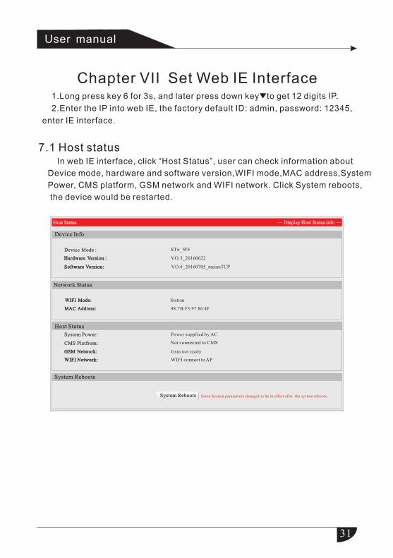
7.1 Host status In web IE interface, click “Host Status”, user can check information about
Device mode, hardware and software version,WIFI mode,MAC address,System
Power, CMS platform, GSM network and WIFI network. Click System reboots,
the device would be restarted.
ST6_WF
Hardware Version : Hardware Version : VO.3_20160622
Software Version: Software Version: VO.4_20160705_meianTCP
WIFI Mode: WIFI Mode: Station
MAC Address: MAC Address: 98:7B:F3:97:86:4F
Some System parameters changed,to be in effect after the system reboots.System RebootsSystem Reboots
Host StatusHost Status
Device InfoDevice Info
Device Mode :Device Mode :
Network StatusNetwork Status
Display Host Status infoDisplay Host Status info
Host StatusHost Status
Power supplied by AC
CMS Platfrom: CMS Platfrom:
GSM Network: GSM Network: Gsm not ready
WIFI Network: WIFI Network: WIFI connect to AP
System RebootsSystem Reboots
Not connected to CMS
System Power:System Power:
32
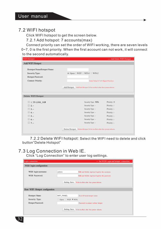
7.3 Log Connection in Web IE. Click “Log Connection” to enter user log settings.
7.2.2 Delete WIFI hotspot: Select the WIFI need to delete and click button”Delete Hotspot”
User manual
Security Type: Security Type: Open WEP WPA1 WPA2
Add New Hotspot,To be in effect after the system reboots.
Delete Hotspot,To be in effect after the system reboots.
1. TP-LINK_3GW
2. –
3. –
4. –
5. –
6. –
7. –
2. –
3. –
4. –
5. –
6. –
7. –
2. –
3. –
4. –
5. –
6. –
7. –
1. TP-LINK_3GW
Enter Value 0-7 (0=Higest Priority)
WPASecurity Type:
Security Type: -
Security Type: -
Security Type: -
Security Type: -
Security Type: -
Security Type: -
WPA
WIFI Hotspot Add Delete WIFI Hotspot
Delete Hotspot
Add WIFI HotspotAdd WIFI Hotspot
Hotstpot NameHotspot Name:Hotstpot NameHotspot Name:
Hotspot Pasword:Hotspot Pasword:
Connect Priority: Connect Priority:
Delete WIFI HotspotDelete WIFI Hotspot
Add Hotspot
Prioity :0
Prioity :-
Prioity :-
Prioity :-
Prioity :-
Prioity :-
Prioity :-
WEB login username:WEB login username:
To be in effect after the system reboots.
Hotstpot Name: Hotstpot Name:
Open WEP WPA
Password to connect to Host hotspot
To be in effect after the system reboots.
WEB Password:WEB Password:
Host AP mode hotspot name
Hotspot Password: Hotspot Password:
Setting Save
Setting Save
WEB login configuration WEB login configuration
and Mobile App local login by this username.WEB
Host WIFI Hotspot configurationHost WIFI Hotspot configuration
admin
WIFI_PANEL
and Mobile App local login by this password.WEB
Security Type:Security Type:
Login connection Set WEB Login and hotspot connection
7.2 WIFI hotspotClick WIFI hotspot to get the screen below.
7.2.1 Add hotspot: 7 accounts(max)Connect priority can set the order of WIFI working, there are seven levels
0~7, 0 is the first priority. When the first account can not work, it will connect
to the second automatically.
33
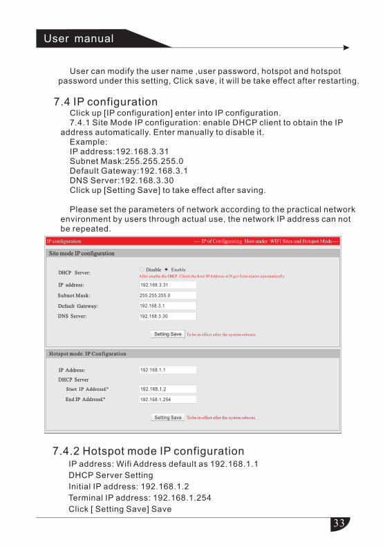
User can modify the user name ,user password, hotspot and hotspot password under this setting, Click save, it will be take effect after restarting.
7.4 IP configuration Click up [IP configuration] enter into IP configuration. 7.4.1 Site Mode IP configuration: enable DHCP client to obtain the IP address automatically. Enter manually to disable it. Example: IP address:192.168.3.31 Subnet Mask:255.255.255.0 Default Gateway:192.168.3.1 DNS Server:192.168.3.30 Click up [Setting Save] to take effect after saving.
Please set the parameters of network according to the practical network environment by users through actual use, the network IP address can not be repeated.
7.4.2 Hotspot mode IP configuration IP address: Wifi Address default as 192.168.1.1
DHCP Server Setting
Initial IP address: 192.168.1.2
Terminal IP address: 192.168.1.254
Click [ Setting Save] Save
User manual
IP of Configurating Host under WIFI Sites and Hotspot Mode
After enable the DHCP Client the host IP Address will get from router automatically
IP address:IP address:
Default Gateway:Default Gateway:
DNS Server:DNS Server:
To be in effect after the system reboots.
DHCP Server:DHCP Server:
Subnet Mask:Subnet Mask:
Disable Enable
255.255.255.0
192.168.3.31
192.168.3.1
192.168.3.30
Setting Save
IP configuration
Site mode IP configurationSite mode IP configuration
DHCP ServerDHCP Server
Start IP Address£°Start IP Address£°
End IP Address£°End IP Address£°
To be in effect after the system reboots.
IP Address:IP Address: 192.168.1.1
192.168.1.2
192.168.1.254
Setting Save
Hotspot mode IP ConfigurationHotspot mode IP Configuration
34
Phone Number 2:Phone Number 2:
Dial Tiems 1-15,default is 5 tims.
Setting Save
Setting Save
---Set Host CMS platform---
Server IP Address: Server IP Address:
Server Account:Server Account:
Server Password:Server Password:
Platform Addres can be IP or Domain name.
Setting Save
Host Setting
Network CMS platform settingsNetwork CMS platform settings
Server Address:Server Address: 0.0.0.0
Server Port: Server Port: 18034
Login Account:Login Account: 987BF397864F
Login Password:Login Password: 012345
Server Port:Server Port: 7974
User Account :User Account : 0000
Dial Times:Dial Times: 5
Phone CMS SettingPhone CMS Setting
Phone Number 1:Phone Number 1:
Mobile APP SettingMobile APP Setting
User manual
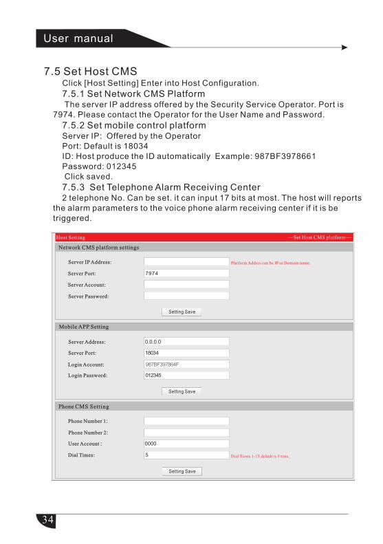
7.5 Set Host CMS Click [Host Setting] Enter into Host Configuration.
7.5.1 Set Network CMS Platform The server IP address offered by the Security Service Operator. Port is 7974. Please contact the Operator for the User Name and Password.
7.5.2 Set mobile control platform Server IP: Offered by the Operator Port: Default is 18034 ID: Host produce the ID automatically Example: 987BF3978661 Password: 012345 Click saved.
7.5.3 Set Telephone Alarm Receiving Center 2 telephone No. Can be set. it can input 17 bits at most. The host will reports the alarm parameters to the voice phone alarm receiving center if it is be triggered.
35
Follow me phone number SettingFollow me phone number Setting
Phone Number 1:Phone Number 1:
Dial Tiems 1-15, default is 5 tims.
Phone Number 2:Phone Number 2:
Phone Number 3:Phone Number 3:
SSL Encryption
Access Point (APN):Access Point (APN):
User Name:User Name:
User Password:User Password:
Setting Save
Setting Save
Setting Save
Email Set t ingEmail Set t ing
GPRS APN Setting GPRS APN Setting
SMTP Server:SMTP Server:
SMTP Port:SMTP Port:
Email Login Username :Email Login Username :
Email Login Password:Email Login Password:
Outbox Address:Outbox Address:
Inbox Address:Inbox Address:
25
Dial Times:Dial Times: 5
Phone Number 4:Phone Number 4:
User manual
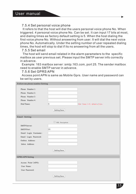
7.5.4 Set personal voice phone It refers to that the host will dial the users personal voice phone No. When triggered. 4 personal voice phone No. Can be set. It can input 17 bits at most,
and dialing times as factory default setting is 5. When the host dialing the first voice phone No. Without answering from user. It will dial the next voice phone No. Automatically. Under the setting number of user repeated dialing times, the host will stop to dial if its no answering from all the users.
7.5.5 Set email The host will send email related in the alarm parameters to the specific
mailbox as user previous set. Please input the SMTP server info correctly in advance.Example: 163 mailbox server :smtp.163.com, port 25. The sender mailbox
need to enable SMTP server in advance.
7.5.6 Set GPRS APNAccess point APN is same as Mobile Gprs. User name and password can
be set by users.
36
User manual
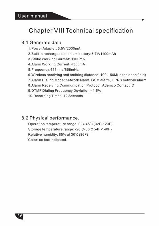
Chapter VIII Technical specification
8.1 Generate data
<
<
<
1.Power Adapter: 5.5V/2000mA
2.Built in rechargeable lithium battery:3.7V/1100mAh
3.Static Working Current: 100mA
4.Alarm Working Current: 300mA
5.Frequency:433mhz/868mHz
6.Wireless receiving and emitting distance: 100-150M(in the open field)
7.Alarm Dialing Mode: network alarm, GSM alarm, GPRS network alarm
8.Alarm Receiving Communication Protocol: Ademco Contact ID
9.DTMF Dialing Frequency Deviation: 1.5%
10.Recording Times: 12 Seconds
8.2 Physical performance.Operation temperature range: 0℃ -45℃ (32F-120F)
Storage temperature range: -20℃ -60℃ (-4F-140F)
Relative humidity: 85% at 30℃ (86F)
Color: as box indicated.
37
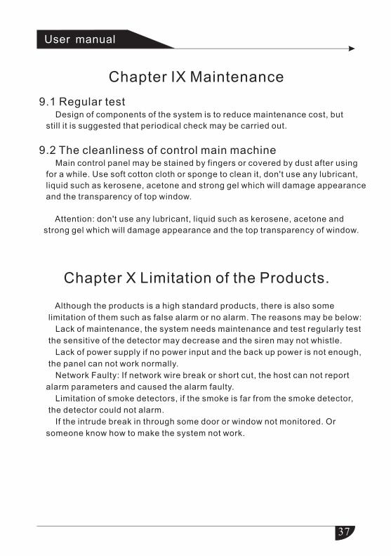
Chapter IX Maintenance
Chapter X Limitation of the Products.
User manual
Although the products is a high standard products, there is also some
limitation of them such as false alarm or no alarm. The reasons may be below:
Lack of maintenance, the system needs maintenance and test regularly test
the sensitive of the detector may decrease and the siren may not whistle.
Lack of power supply if no power input and the back up power is not enough,
the panel can not work normally.
Network Faulty: If network wire break or short cut, the host can not report
alarm parameters and caused the alarm faulty.
Limitation of smoke detectors, if the smoke is far from the smoke detector,
the detector could not alarm.
If the intrude break in through some door or window not monitored. Or
someone know how to make the system not work.
9.1 Regular test Design of components of the system is to reduce maintenance cost, but
still it is suggested that periodical check may be carried out.
9.2 The cleanliness of control main machineMain control panel may be stained by fingers or covered by dust after using
for a while. Use soft cotton cloth or sponge to clean it, don't use any lubricant,
liquid such as kerosene, acetone and strong gel which will damage appearance
and the transparency of top window.
Attention: don't use any lubricant, liquid such as kerosene, acetone and
strong gel which will damage appearance and the top transparency of window.