Wideband Rectangular Microstrip Patch Antenna Using … · RADIOENGINEERING, VOL. 16, NO. 3,...
5
RADIOENGINEERING, VOL. 16, NO. 3, SEPTEMBER 2007 37 Wideband Rectangular Microstrip Patch Antenna Using L-Probe Feeding System Pavel HAZDRA, Miloš MAZÁNEK, Jiří ČERMÁK Dept. of Electromagnetic Field, Czech Technical University, Technická 2, 166 27 Praha, Czech Republic [email protected] Abstract. Paper focuses on so-called L-probe feeding technique suitable for wideband (>30% relative band- width) driving of microstrip patch antennas. Physical ex- planation, simulation and measurement are presented. Further modification for improvement of radiation cha- racteristic is also proposed. Keywords Microstrip patch antenna, L-probe, wideband anten- nas, proximity coupling. 1. Introduction Microstrip patch antennas are usually designed to have small relative bandwidth (BW), 3-10%. Usually the feeding system is a major bandwidth limitation. L-probe [1] driving technique is able to increase relative BW more than 30% while keeping reasonable radiation properties. 2. Principle of Operation First let’s have a look to the sketch of the patch an- tenna with the L-probe feed (Fig. 1). Fig. 1. Rectangular patch antenna with the L-probe feed. Basically, the structure could be seen as a patch antenna electromagnetically coupled to the L-shaped capacitively loaded monopole. Both the monopole and patch have its own resonances which, if properly combined, give rise to a broadband behavior. Moreover, L-shaped monopole near field (Fig. 3) coincides with the eigen-field of the TM 01 patch mode thus effective coupling patch-probe is possible. Fig. 2. Parametric analysis on bandwidth. Fig. 3. E field distribution of the L-probe only. Fig. 4. E field distribution of the L-probe with the patch. A result of an extensive bandwidth-related parametric study of sample structure with L = 56 mm, W = 37 mm, H = 23 mm and D = 0 is shown in Fig. 2. It can be clearly
Transcript of Wideband Rectangular Microstrip Patch Antenna Using … · RADIOENGINEERING, VOL. 16, NO. 3,...
RADIOENGINEERING, VOL. 16, NO. 3, SEPTEMBER 2007 37
Wideband Rectangular Microstrip Patch Antenna Using L-Probe Feeding System
Pavel HAZDRA, Miloš MAZÁNEK, Jiří ČERMÁK
Dept. of Electromagnetic Field, Czech Technical University, Technická 2, 166 27 Praha, Czech Republic
Abstract. Paper focuses on so-called L-probe feeding technique suitable for wideband (>30% relative band-width) driving of microstrip patch antennas. Physical ex-planation, simulation and measurement are presented. Further modification for improvement of radiation cha-racteristic is also proposed.
Keywords Microstrip patch antenna, L-probe, wideband anten-nas, proximity coupling.
1. Introduction Microstrip patch antennas are usually designed to
have small relative bandwidth (BW), 3-10%. Usually the feeding system is a major bandwidth limitation. L-probe [1] driving technique is able to increase relative BW more than 30% while keeping reasonable radiation properties.
2. Principle of Operation First let’s have a look to the sketch of the patch an-
tenna with the L-probe feed (Fig. 1).
Fig. 1. Rectangular patch antenna with the L-probe feed.
Basically, the structure could be seen as a patch antenna electromagnetically coupled to the L-shaped capacitively loaded monopole. Both the monopole and patch have its
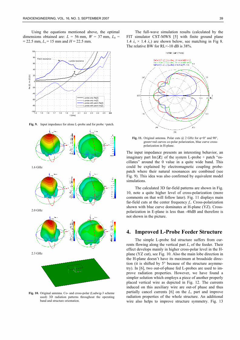
own resonances which, if properly combined, give rise to a broadband behavior. Moreover, L-shaped monopole near field (Fig. 3) coincides with the eigen-field of the TM01 patch mode thus effective coupling patch-probe is possible.
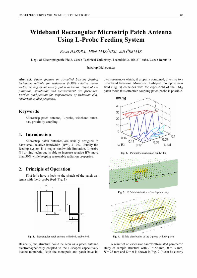
Fig. 2. Parametric analysis on bandwidth.
Fig. 3. E field distribution of the L-probe only.
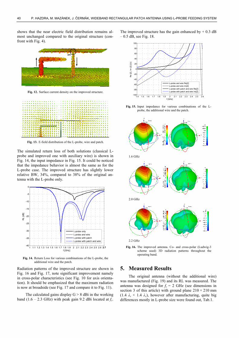
Fig. 4. E field distribution of the L-probe with the patch.
A result of an extensive bandwidth-related parametric study of sample structure with L = 56 mm, W = 37 mm, H = 23 mm and D = 0 is shown in Fig. 2. It can be clearly

38 P. HAZDRA, M. MAZÁNEK, J. ČERMÁK, WIDEBAND RECTANGULAR PATCH ANTENNA USING L-PROBE FEEDING SYSTEM
distinguished how the bandwidth is influenced by a vari-ation of Lv and Lh (described in Fig. 1); the result is shown in Fig. 2. Dielectric used in simulations was air.
From the analysis, we can observed that the biggest relative bandwidth (referred to condition RL<-10dB) is obtained for Lh between 0.14 – 0.19 λc and Lv between 0.08 and 0.11 λc. Deeper study gives the best values Lh = 0.15 λc and Lv = 0.1 λs. So, the complete length of the feeder is equal to the “monopole” length λc/4 (see Fig. 3) at the de-sign frequency fc (will be discussed later). Consequently, the L-probe system could be viewed as a capacitively loaded monopole electromagnetically coupled to the TM01 field under the patch (Fig. 4).
Fig. 5. Equivalent circuit model for the L-probe and the patch.
In order to physically explain the structure behavior, we have proposed the following equivalent circuit (Fig. 5).
Fig. 6. Parasitic components appearing in the equivalent circuit
(some capacitors were merged for clearness).
The patch antenna is modeled as parallel RLC circuit (al-ternatively it could be represented using a transmission line model [2]) and the L-probe as a stub consisting of 2 ideal lines. Interaction between the patch and the horizontal arm of the feeder is accounted through coupled lines (MACLIN component). Other elements model parasitic components.
RL [dB]
Fig. 7. Return Loss - Equivalent circuit modeling and IE3D full-
wave simulation.
Comparison of IE3D [3] full-wave MoM simulation and the equivalent circuit (transmission line and RLC model [2] of the patch) modeling of the RL is shown in Fig. 7.
2.1 Design Guidelines Based on number of parametric simulations we are
able to point out two fundamental steps for the design of the proposed broadband (relative BW~38%) patch antenna with the center frequency fc. Let us consider dielectric to be air, thus λc=c0/fc.
• The design of the rectangular L × W patch: The resonant length of the patch L is obtained by the following equation:
830
cfc
L = . (1)
The above equation takes into account both the frin-ging field effect and the fact that the patch resonance has to be shifted below the fc frequency by roughly 10% in order to obtain broadband behavior. The width of the patch W isn’t a crucial design pa-rameter, however we have determined its optimal value in terms of radiation characteristics to be W=2/3L, see also [4].
• The L-probe design: The optimal BW performance has been obtained for: Lh = 0.15 λc, Lv = 0.10 λc, H = 0.15 λc. (Note that Lh+Lv = 0.25 λc.)
To verify the proposed design strategy, several antennas (with different center frequencies fc) were successfully simulated using relations described above.
3. Results The example of the L-probe fed patch for fc = 2GHz:
1 1.1 1.2 1.3 1.4 1.5 1.6 1.7 1.8 1.9 2 2.1 2.2 2.3 2.4 2.5 2.6-40
-35
-30
-25
-20
-15
-10
-5
0
f [GHz]
RL
[dB
]
L-probe onlyL-probe with patch
Fig. 8. Calculated Return Loss for alone L-probe and L-probe
together with the patch.
RADIOENGINEERING, VOL. 16, NO. 3, SEPTEMBER 2007 39
Using the equations mentioned above, the optimal dimensions obtained are: L = 56 mm, W = 37 mm, Lh = = 22.5 mm, Lv = 15 mm and H = 22.5 mm.
1.4 1.5 1.6 1.7 1.8 1.9 2 2.1 2.2 2.3 2.4 2.5 2.62.6-100
-80
-60
-40
-20
0
20
40
60
80
100
f [GHz]
Re
{Z},
Im {Z
} [Ω
]
L-probe only Re[Z]L-probe only Im[Z]L-probe with patch Re[Z]L-probe with patch Im[Z]
Patch resonanceL-probe resonance
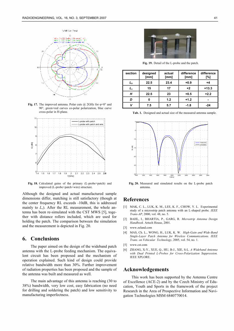
Fig. 9. Input impedance for alone L-probe and for probe +patch.
1.6 GHz
2.0 GHz
2.3 GHz
Fig. 10. Original antenna. Co- and cross-polar (Ludwig-3 scheme
used) 3D radiation patterns throughout the operating band and structure orientation.
The full-wave simulation results (calculated by the FIT simulator CST-MWS [5] with finite ground plane 1.4 λc × 1.4 λc) are shown below, see matching in Fig 8. The relative BW for RL<-10 dB is 38%.
Fig. 11. Original antenna. Polar cuts @ 2 GHz for φ=0° and 90°,
green+red curves co-polar polarization, blue curve cross-polarization in H-plane.
The input impedance presents an interesting behavior, an imaginary part Im{Z} of the system L-probe + patch “os-cillates” around the 0 value in a quite wide band. This could be explained by electromagnetic coupling probe-patch where their natural resonances are combined (see Fig. 9). This idea was also confirmed by equivalent model simulations.
The calculated 3D far-field patterns are shown in Fig. 10, note a quite higher level of cross-polarization (more comments on that will follow later). Fig. 11 displays main far-field cuts at the center frequency fc. Cross-polarization shown with blue curve dominates at H-plane (YZ). Cross-polarization in E-plane is less than -40dB and therefore is not shown in the picture.
4. Improved L-Probe Feeder Structure The simple L-probe fed structure suffers from cur-
rents flowing along the vertical part Lv of the feeder. Their effect develops mainly in higher cross-polar level in the H-plane (YZ cut), see Fig. 10. Also the main lobe direction in the H-plane doesn’t have its maximum at broadside direc-tion (it is shifted by 5° because of the structure asymme-try). In [6], two out-of-phase fed L-probes are used to im-prove radiation properties. However, we have found a simpler solution which employs a piece of another properly placed vertical wire as depicted in Fig. 12. The currents induced on this auxiliary wire are out-of phase and thus partially cancel currents [6] on the Lv part and improve radiation properties of the whole structure. An additional wire also helps to improve structure symmetry. Fig. 13
40 P. HAZDRA, M. MAZÁNEK, J. ČERMÁK, WIDEBAND RECTANGULAR PATCH ANTENNA USING L-PROBE FEEDING SYSTEM
shows that the near electric field distribution remains al-most unchanged compared to the original structure (con-front with Fig. 4).
gap
Fig. 12. Surface current density on the improved structure.
Fig. 13. E-field distribution of the L-probe, wire and patch.
The simulated return loss of both solutions (classical L-probe and improved one with auxiliary wire) is shown in Fig. 14, the input impedance in Fig. 15. It could be noticed that the impedance behavior is almost the same as for the L-probe case. The improved structure has slightly lower relative BW, 34%, compared to 38% of the original an-tenna with the L-probe only.
1 1.1 1.2 1.3 1.4 1.5 1.6 1.7 1.8 1.9 2 2.1 2.2 2.3 2.4 2.5 2.6 2.72.7-40
-35
-30
-25
-20
-15
-10
-5
0
f [GHz]
RL
[dB
]
L-probe onlyL-probe and wireL-probe with patchL-probe with patch and wire
Fig. 14. Return Loss for various combinations of the L-probe, the
additional wire and the patch.
Radiation patterns of the improved structure are shown in Fig. 16 and Fig. 17, note significant improvement namely in cross-polar characteristics (see Fig. 10 for axis orienta-tion). It should be emphasized that the maximum radiation is now at broadside (see Fig. 17 and compare it to Fig. 11).
The calculated gains display G > 8 dBi in the working band (1.6 – 2.3 GHz) with peak gain 9.2 dBi located at fc.
The improved structure has the gain enhanced by + 0.3 dB – 0.5 dB, see Fig. 18.
1.4 1.5 1.6 1.7 1.8 1.9 2 2.1 2.2 2.3 2.4 2.5 2.6-100
-80
-60
-40
-20
0
20
40
60
80
100
f [GHz]
Re
{Z},
Im {Z
} [Ω
]
L-probe and wire Re[Z]L-probe and wire Im[Z]L-probe with patch and wire Re[Z]L-probe with patch and wire Im[Z]
Fig. 15. Input impedance for various combinations of the L-
probe, the additional wire and the patch.
1.6 GHz
2.0 GHz
2.2 GHz
Fig. 16. The improved antenna. Co- and cross-polar (Ludwig-3 scheme used) 3D radiation patterns throughout the operating band.
5. Measured Results The original antenna (without the additional wire)
was manufactured (Fig. 19) and its RL was measured. The antenna was designed for fc = 2 GHz (see dimensions in section 3 of this article) with ground plane 210 × 210 mm (1.4 λc × 1.4 λc), however after manufacturing, quite big differences mostly in L-probe size were found out, Tab.1.
RADIOENGINEERING, VOL. 16, NO. 3, SEPTEMBER 2007 41
Fig. 17. The improved antenna. Polar cuts @ 2GHz for φ=0° and
90°, green+red curves co-polar polarization, blue curve cross-polar in H-plane.
1.4 1.5 1.6 1.7 1.8 1.9 2 2.1 2.2 2.3 2.4 2.5 2.62.65
6
7
8
9
10
11
f [GHz]
G [d
Bi]
L-probe with patchL-probe with patch and wire
Fig. 18. Calculated gains of the primary (L-probe+patch) and
improved (L-probe+patch+wire) structure.
Although the designed and actual manufactured sample dimensions differ, matching is still satisfactory (though at the center frequency RL exceeds -10dB, this is addressed mainly to Lv). After the RL measurement, the whole an-tenna has been re-simulated with the CST MWS [5], toge-ther with distance rollers included, which are used for holding the patch. The comparison between the simulation and the measurement is depicted in Fig. 20.
6. Conclusions The paper aimed on the design of the wideband patch
antenna with the L-probe feeding mechanism. The equiva-lent circuit has been proposed and the mechanism of operation explained. Such kind of design could provide relative bandwidth more than 30%. Further improvement of radiation properties has been proposed and the sample of the antenna was built and measured as well.
The main advantage of this antenna is reaching (30 to 38%) bandwidth, very low cost, easy fabrication (no need for drilling and soldering the patch) and low sensitivity to manufacturing imperfectness.
Fig. 19. Detail of the L-probe and the patch.
section designed [mm]
actual [mm]
difference [mm]
difference [%]
Lh 22.5 23.4 +0.9 +4
Lv 15 17 +2 +13.3
H 22.5 23 +0.5 +2.2
D 0 1.2 +1.2 -
V 7.5 5.7 -1.8 -24
Tab. 1. Designed and actual size of the measured antenna sample.
1000 1200 1400 1600 1800 2000 2200 2400 2600 2800 3000-30
-25
-20
-15
-10
-5
0
f [MHz]
RL
[dB
]
measuredsimulated
Fig. 20. Measured and simulated results on the L-probe patch
antenna.
References [1] MAK, C. L., LUK, K. M., LEE, K. F., CHOW, Y. L. Experimental
study of a microstrip patch antenna with an L-shaped probe. IEEE Trans-AP, 2000, vol. 48, no. 5.
[2] BAHL, I., BHARTIA, P., GARG, R. Microstrip Antenna Design Handbook. Artech House, 2001.
[3] www.zeland.com [4] MAS, Ch. L., WONG, H., LUK, K. W. High-Gain and Wide-Band
Single-Layer Patch Antenna for Wireless Communications. IEEE Trans. on Vehicular Technology, 2005, vol. 54, no. 1.
[5] www.cst.com [6] ZHANG, X-Y., XUE, Q., HU, B-J., XIE, S-L. A Wideband Antenna
with Dual Printed L-Probes for Cross-Polarization Suppression. IEEE XPLORE.
Acknowledgements This work has been supported by the Antenna Centre
of Excellence (ACE-2) and by the Czech Ministry of Edu-cation, Youth and Sports in the framework of the project Research in the Area of Prospective Information and Navi-gation Technologies MSM 6840770014.