
Wide-field Infra-red Survey Explorer - launched Dec 2009 1 ...
10
Wide-field Infra-red Survey Explorer - launched Dec 2009 1:24 scale • WISE will scan the entire sky at infrared wavelengths, creating the most comprehensive catalog yet of dark and dim objects in the cosmos: vast dust clouds, brown dwarf stars, asteroids -- even large, nearby asteroids that might pose a threat to Earth. Surveys of nearby asteroids based on visible-light telescopes could be skewed toward asteroids with more-reflective surfaces. The full-sky infrared map produced by WISE will reveal even these darker asteroids, mapping the locations and sizes of roughly 200,000 asteroids and giving scientists a clearer idea of how many large and potentially dangerous asteroids are nearby. WISE will also help answer questions about the formation of stars and the evolution and structure of galaxies, including our own Milky Way galaxy. • To achieve its unprecedented sensitivity to infrared radiation (heat), WISE will cool its components to about 15 degrees Celsius above absolute zero (minus 258 degrees Celsius, or minus 433 degrees Fahrenheit) using a block of solid hydrogen. Scientists chose solid hydrogen over liquid helium, which is often used in research for cooling materials to near absolute zero, because a smaller volume of solid hydrogen can do the job. • After launch, WISE will spend six months mapping the sky. Analyzing that data should give scientists some new insights into the cosmos. WISE will be able to detect infrared emissions from the most active star-forming regions. This will help scientists know how rapidly stars are formed during galactic collisions, which could indicate how many of the universe's stars were formed this way. WISE will also target dim "failed stars" called brown dwarfs that outnumber ordinary stars by a wide margin. Mapping brown dwarfs in the Milky Way may reveal much about the structure and evolution of our own galaxy. Panoramic view of the entire near-infrared sky reveals the distribution of galaxies beyond the Milky Way.
Transcript of Wide-field Infra-red Survey Explorer - launched Dec 2009 1 ...

Wide-field Infra-red Survey Explorer - launched Dec 2009 1:24 scale
• WISE will scan the entire sky at infrared wavelengths, creating the most comprehensive catalog yet of dark and dim objects in the cosmos: vast dust clouds, brown dwarf stars, asteroids -- even large, nearby asteroids that might pose a threat to Earth.Surveys of nearby asteroids based on visible-light telescopes could be skewed toward asteroids with more-reflective surfaces. The full-sky infrared map produced by WISE will reveal even these darker asteroids, mapping the locations and sizes of roughly 200,000 asteroids and giving scientists a clearer idea of how many large and potentially dangerous asteroids are nearby. WISE will also help answer questions about the formation of stars and the evolution and structure of galaxies, including our own Milky Way galaxy.
• To achieve its unprecedented sensitivity to infrared radiation (heat), WISE will cool its components to about 15 degrees Celsiusabove absolute zero (minus 258 degrees Celsius, or minus 433 degrees Fahrenheit) using a block of solid hydrogen. Scientists chose solid hydrogen over liquid helium, which is often used in research for cooling materials to near absolute zero, because a smaller volume of solid hydrogen can do the job.
• After launch, WISE will spend six months mapping the sky. Analyzing that data should give scientists some new insights into the cosmos. WISE will be able to detect infrared emissions from the most active star-forming regions. This will help scientists know how rapidly stars are formed during galactic collisions, which could indicate how many of the universe's stars were formed this way. WISE will also target dim "failed stars" called brown dwarfs that outnumber ordinary stars by a wide margin. Mapping brown dwarfs in the Milky Way may reveal much about the structure and evolution of our own galaxy.
Panoramic view of the entire near-infrared sky reveals the distribution of galaxies beyond the Milky Way.

• Score all fold lines before cutting out parts. Study the diagrams and photos before starting. Note the blue and red stars for alignment.• Cryostat
– Cut our the upper rim (part 1), curve and glue into a shallow conic. Cut out the cryostat body (2), roll into a cylinder and glue using the tab on the end. Bend the teeth at the top of the body inward slightly, apply glue, and attach the upper rim (1) to the top of the body (2). Cut out the lower rim and bottom (3 & 4), curve and glue the lower rim into a shallow conic. Bend the teeth at the bottom of the body assembly inward, apply glue, and attach the lower rim. When dry, bend the teeth on the inner edge of the lower rim inward, apply glue, and attach the bottom.
– Optional optics. If you intend to build the optical barrel use parts 5-9. If not, cut out the alternate upper rim (5a), fold the tabs at the top of the cryostat assembly inward, apply glue, and attach the alternate upper rim.
• To build a more detailed model, cut out parts 5-9. Roll the inner optical barrel (6) into a cylinder with the printed side inward and glue using the tab at the edge. Bend the tabs at the bottom of the barrel inward. Apply glue and insert the primary mirror (7), printed side up, into the top of the barrel, push it down inside and press it down onto the tabs to secure.
• Cut out the two parts for the secondary mirror support (8). Score the gray lines and cut on the red lines. Fold each part lengthwise, then fold the long legs outward to make a “T” – it should look like the depiction under the parts on the parts sheet. Glue only the doubled section. When both parts are prepared, glue together the open legs of each “T” to make a cross (make sure the tabs at the ends do not get glued together, you’ll need them open to attach the support to the barrel). Glue the two sides of the secondary mirror (9) together (printed sides out), then glue the black side to the center of the mirror support.
• Bend open the tabs at the ends of the mirror support and position the assembly (yellow side of the secondary mirror goes down/toward the primary mirror) into the top of the optical barrel (about ¼ inch/5 mm below the top edge) and glue in place.
• Bend the tabs on the top of the optical barrel assembly outward, apply glue, and attach the inner ring for the upper rim (5). When dry, bend the tabs on the upper rim of the cryostat assembly inward, apply glue, and attach the upper ring/optical barrel assembly.
– Light shade. Cut out the sun shade (10 & 11), curve part 10 – printed side outward – into a conic and secure using the tab at the edge. Curve part 11 – printed side inward – and position it inside part 10 to determine its final size. Trim the end of part 11 to fit and secure inside part 10. Apply glue to the bottom edge (smaller end) of the light shade and glue to the top of the cryostat assembly with the outer seam on the light shade on the opposite side of the two vertical gray lines on the cryostat body (see picture, you will eventually cut the upper edge of the shade at an angle marked by the light gray line on the outer shade – the low spot should be aligned with the double manifold by the blue star on the parts sheet).
– Manifolds. Cut out the manifolds (12) and glue to thick card. When dry, slightly curve the manifolds and glue them to the cryostat upper rim, positioned as shown on the parts sheet and diagrams. Cut out parts 13 and fold the lower section into a box, then glue. You should end up with a box on top of a long, flat section. Attach the flat section to the rectangular outlines on lower the cryostat body as shown; the boxes hang below the cryostat.
– Support struts. Cut out the 8 support struts (14), roll into long cylinders and glue. Cut out the four upper brackets (15). Cut the mounting tabs free (short red line). Fold the sides up to make a u-channel with doubled side parts and glue. Then, fold the mounting tabs on the bottom of the brackets inward. Bend the small tab at the top of each strut inward and glue it to the underside of the bracket tab (printed face to printed face). Glue the brackets to the cryostat – the lower tabs on each strut will be attached to the spacecraft bus later. Refer to pictures of completed model for reference.
Wide-field Infra-red Survey Explorer 1:24 scale
Copyright 2009 – John Jogerst. Not for commercial use; for personal or educational use only.

• Photovoltaic Assembly (PVA). Cut out the low gain antenna (23, 24). Fold the antenna face as indicated and glue. Fold the LGA mount into a box and glue. Cut out the PVA and its mounting (25, 26). Fold down the sides and tabs of the PVA (25) to form a flat, box-like part. Glue the corner tabs first to form the sides. Then, with the PVA face down on a flat surface (to ensure it stays flat), carefully fold in the remaining tabs and glue down the back (gray side) of the PVA. Glue the LGA mount to the top, center of the PVA, between the dotted lines, making sure the gray and charcoal faces match. Glue the oval LGA (23) to the mount on the front face of the assembly. Roll the PVA mount (26) into a cylinder and glue using the tab at the end. Fold in the tabs on the end of the mount with the short lines, apply glue and attach to the PVA over the dotted circle on the back.
• High Gain Antenna (HGA). Cut out the parts (19, 20, 21). Roll the rim (21) into a ring and secure. Bend the tabs inward and glue the front (19) and back (20) faces of the HGA to the rim. Cut out the HGA mounting posts (22), roll into short cylinders and glue. Attach the mounting posts to the back face of the HGA over the small printed circles. Cut out the associated LGA (16, 17, 18). Fold the antenna face (16) and mounting arm (17) in half and glue. Roll the mounting post (18) into a cylinder and secure. Bend the light colored tab on the mounting arm down 90 degrees (best done before the glue sets), then glue the mounting post (18) to the narrow end of the mounting arm (dotted circle). The antenna face (16) will be glued centered on the mounting post, though it is best to do this after the HGA is mounted to the bus.
• Spacecraft bus. Cut out the spacecraft bus parts (27-31). Fold the tabs on the side panels of the main body (27) inward. Glue up the side panels to make an 8-sided box, then fold down the bottom (light gray side) and glue to the tabs to close the box. Roll the payload mounting ring (29) into a circle and glue, then bend the tabs inward. Glue the base (28) to the inside of the ring, matching the unprinted side of the base with the unprinted side of the tabs. Roll the lower conic (30) into a shallow cone and glue. Glue the wide end of part 30 to the rim of the unprinted side of part 31. Fold the tabs of the completed assembly inward and glue the base (28+29) in place. Glue the main body to the top of the lower assembly as noted on the parts (red stars indicate alignment – blue marking on base aligns with panel having a single star tracker).
– Cut out the two star trackers (34, 35, 37) and brackets (36). Roll the body (35) into a cylinder and glue, then fold the tabs inward and glue on the top (34). Color the back of the shade (37) black, roll into a cone and glue, then attach to the top of the body. Fold the brackets (36) to form triangular prisms and glue. Glue the brackets to the bus (rectangles marked ST), then glue the trackers to the brackets (refer to pictures for alignment). Cut out the magnetometer (32) and bracket (33). Fold the magnetometer into a small box and glue. Fold the bracket into a long, triangular prism and glue. Attach the magnetometer to the bracket over the red rectangle, then glue the asembly to the bus (rectangle marked M).
• Assembly: glue the cryostat assembly to the main bus, locating the small tab on the bottom of each strut over the dots on the corners of the bus. Use the blue stars for alignment – the two gray vertical lines (manifold side) on the cryostat should be aligned with the white panel with four circles on the bus. Start by gluing one strut in place, then work around sequentially. The strut mounts will bend slightly into alignment, producing a strong assembly when the last strut is attached.
– LGA/HGA – glue the tab on the LGA mounting arm (17) to the “shelf” below the HGA panel (white panel with four circles). Apply glueto the ends of the four HGA mounting posts and glue the HGA in position on the white panel with four circles. Glue the LGA face (16) to the mounting post and position as shown in the pictures.
Wide-field Infra-red Survey Explorer 1:24 scale
Copyright 2009 – John Jogerst. Not for commercial use; for personal or educational use only.

• Assembly:– PVA – fold the tabs on the PVA mount inward and glue to the circle marked PVA on the bus. Make sure the PVA sits level.– Trim the top of the light shade using the dotted line for reference to angle the top edge. The low spot will be on the side with the HGA
and the manifolds (two vertical gray lines) on the cryostat.• You can do several things to add detail to the model.
– Mirror – IR telescopes have gold coated mirrors. Try covering the yellow printed mirror surfaces with gold foil/wrapping paper.– Manifolds and piping – you can add the hydrogen cooling manifolds and piping using thick card to build up the manifolds and thin
strips of card, paper cylinders, or soft wire for piping. Refer to the diagrams and pictures for more detail.– Magnetic torque rods – the blue lines on the sides of the bus are magnetic torque rods the react against the earth’s magnetic field to
position the spacecraft. You can model these with short rods (card, paper tube, toothpicks) glued to the spacecraft’s sides.– There are alternate struts and brackets provided that are useful for building a smaller scale model. Instead of rolling tubes for the
struts, simply glue the alternate struts to thick card and use in place of the original struts and brackets.
Wide-field Infra-red Survey Explorer 1:24 scale
Copyright 2009 – John Jogerst. Not for commercial use; for personal or educational use only.
SECONARY MIRROR SUPPORT OPTICS
STRUTSANDBRACKETS
LOWER PHOTO-VOLTAIC ASSY (PVA) BUSCONIC BASE

STAR TRACKERS
MAGNETOMETER ASSEMBLY
SHADEOPTICS
CRYOSTAT
BASE
HGA
PVA(BACK)
CRYOSTAT
BUS
BUS
PVA
STRUTASSEMBLIES
HGA (BACK)


Wide-field Infra-red Survey Explorer 1:24 scaleCryostat
Lower rimBottom
Upper rim
Upper bracket
Secondary mirror support
Primary mirror
Sun shade – inner, outerTrim after assembly forslanted upper edge.
Roll color inside
Roll color outside. Cut to dottedline after assembly to make angled sunshade.
Glue to card
Inner ringupper rim
TOPStruts
Piping manifolds
1
2
3 4
5
7
8
9
10
11
1213
14
15
Attach manifolds to upper rim after assembly
Copyright 2009 – John Jogerst. Not for commercial use; for personal or educational use only.
FOLD
13
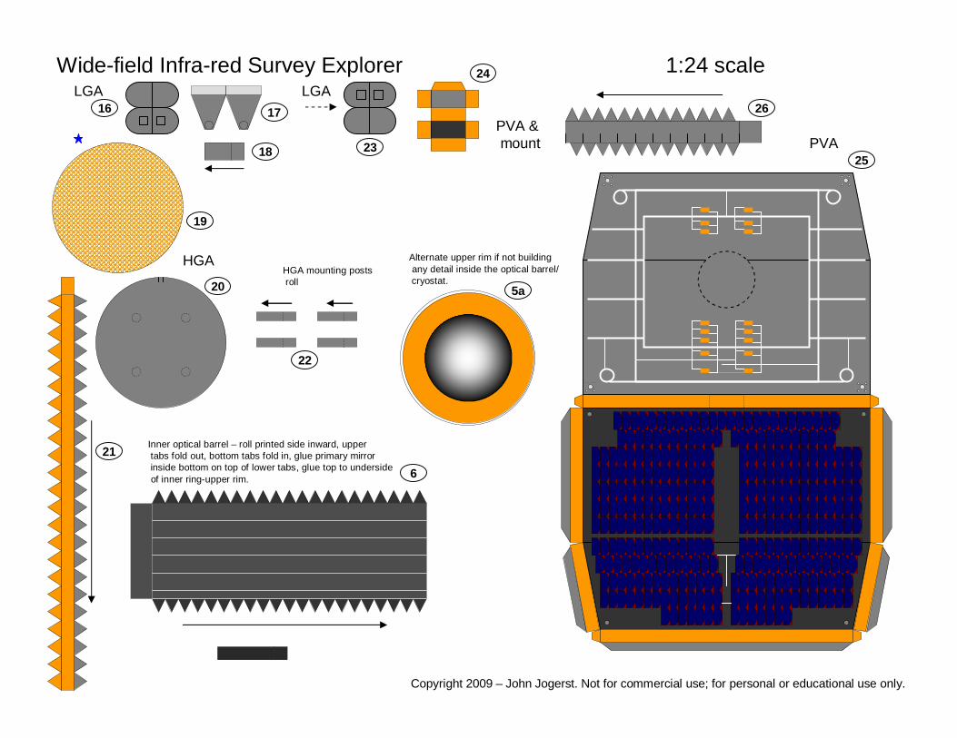
Wide-field Infra-red Survey Explorer 1:24 scale
HGA
PVA
LGA
PVA &mount
Inner optical barrel – roll printed side inward, uppertabs fold out, bottom tabs fold in, glue primary mirrorinside bottom on top of lower tabs, glue top to undersideof inner ring-upper rim.
HGA mounting postsroll
Alternate upper rim if not building any detail inside the optical barrel/cryostat.
LGA
5a
6
16 17
18
19
20
21
22
23
24
25
26
Copyright 2009 – John Jogerst. Not for commercial use; for personal or educational use only.

Wide-field Infra-red Survey Explorer 1:24 scaleSpacecraft bus
Magnetometer & bracket
Star trackers
MOUNT BUSON TOP
GLUE TO WIDE ENDOF LOWER CONIC
Base
Lower conic
Payl
oad
mou
ntin
g rin
g
Alternate struts-glue to card
14a
15a
27
28
29
30
31
32
33
34 35
3637
37
Copyright 2009 – John Jogerst. Not for commercial use; for personal or educational use only.
PVA
M ST ST