Wicker Inferno Patio Heater Model # SRPH80 - … maintenance instructions thoroughly before...
20
Owner’s Manual Questions, problems, missing / replacement parts? Before returning to your retailer, call our customer service department at 1-866-814-0585, 8 a.m.-8 p.m., EST, Monday-Friday. If you smell gas: 1. Shut off gas to the appliance. 2. Extinguish any open flame. 3. If odor continues, keep away from the appliance and immediately call your gas supplier or fire department. Do not store or use gasoline or other flammable vapors and liquids in the vicinity of this or any other appliance. An LP-cylinder not connected for use shall not be stored in the vicinity of this or any other appliance. DANGER WARNING WARNING For Outdoor Use Only. CAUTION: Installer: Leave the manual instructions to the user for future use. Consumer: Please keep this manual for future reference. Read the instructions before use. This appliance must be installed in accordance with such regulations as are in force. Wicker Inferno Patio Heater Model # SRPH80 TM
-
Upload
dangnguyet -
Category
Documents
-
view
218 -
download
0
Transcript of Wicker Inferno Patio Heater Model # SRPH80 - … maintenance instructions thoroughly before...

Owner’s Manual
Questions, problems, missing / replacement parts? Before returning to your retailer,call our customer service department at 1-866-814-0585, 8 a.m.-8 p.m., EST,Monday-Friday.
If you smell gas:1. Shut off gas to the appliance.2. Extinguish any open flame.3. If odor continues, keep away from the appliance and immediately call your gas supplier or fire department.
Do not store or use gasoline or other flammable vapors and liquids in the vicinity of this or any other appliance.An LP-cylinder not connected foruse shall not be stored in the vicinityof this or any other appliance.
DANGER
WARNING
WARNINGFor Outdoor Use Only.
CAUTION:Installer: Leave the manual instructions to the user for future use. Consumer: Please keep this manual for future reference.
Read the instructions before use. This appliance must be installed in accordance with such regulations as are in force.
Wicker Inferno Patio HeaterModel # SRPH80
TM
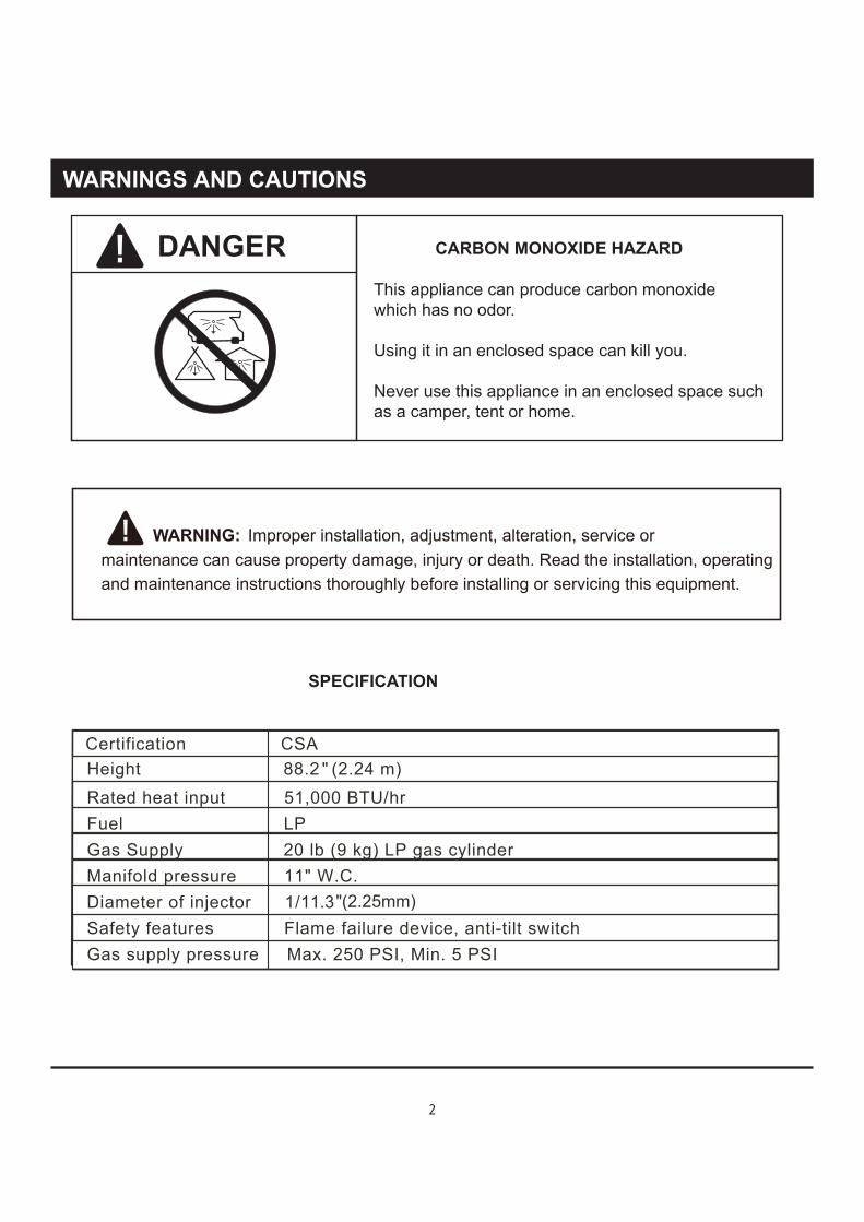
This appliance can produce carbon monoxidewhich has no odor.
Using it in an enclosed space can kill you.
Never use this appliance in an enclosed space suchas a camper, tent or home.
DANGER CARBON MONOXIDE HAZARD
WARNINGS AND CAUTIONS
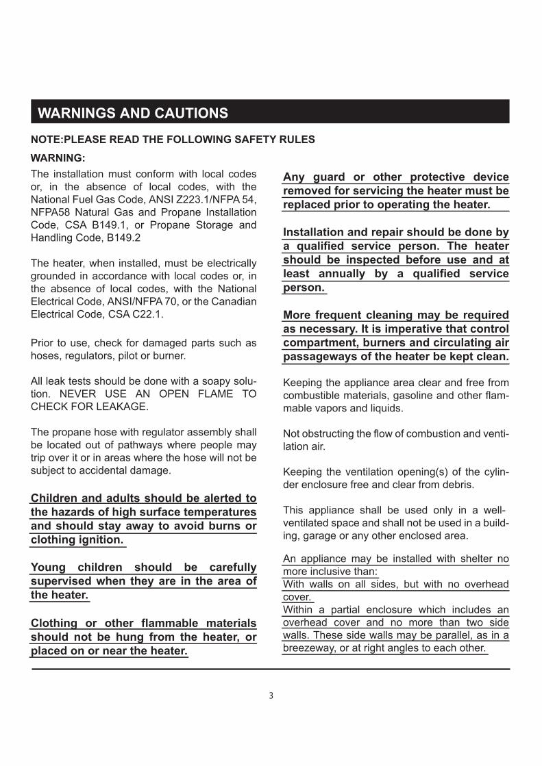
SPECIFICATION
Certification CSAHeight 88.2 "
(2.24 m)
Rated heat input 51,000 BTU/hrFuel LPGas Supply 20 lb (9 kg) LP gas cylinderManifold pressure 11" W.C.Diameter of injector 1/11.3 Safety features Flame failure device, anti-tilt switchGas supply pressure Max. 250 PSI, Min. 5 PSI
WARNING: Improper installation, adjustment, alteration, service or maintenance can cause property damage, injury or death. Read the installation, operating and maintenance instructions thoroughly before installing or servicing this equipment.
2
"(2.25mm)
The installation must conform with local codesor, in the absence of local codes, with theNational Fuel Gas Code, ANSI Z223.1/NFPA 54,NFPA58 Natural Gas and Propane InstallationCode, CSA B149.1, or Propane Storage andHandling Code, B149.2
The heater, when installed, must be electricallygrounded in accordance with local codes or, inthe absence of local codes, with the NationalElectrical Code, ANSI/NFPA 70, or the CanadianElectrical Code, CSA C22.1.
Children and adults should be alerted tothe hazards of high surface temperaturesand should stay away to avoid burns orclothing ignition.
Young children should be carefullysupervised when they are in the area ofthe heater.
Clothing or other flammable materialsshould not be hung from the heater, orplaced on or near the heater.
Prior to use, check for damaged parts such ashoses, regulators, pilot or burner.
All leak tests should be done with a soapy solu-tion. NEVER USE AN OPEN FLAME TOCHECK FOR LEAKAGE.
The propane hose with regulator assembly shallbe located out of pathways where people maytrip over it or in areas where the hose will not besubject to accidental damage.
Any guard or other protective deviceremoved for servicing the heater must be replaced prior to operating the heater.
Installation and repair should be done bya qualified service person. The heatershould be inspected before use and atleast annually by a qualified serviceperson.
More frequent cleaning may be requiredas necessary. It is imperative that controlcompartment, burners and circulating airpassageways of the heater be kept clean.
Keeping the appliance area clear and free fromcombustible materials, gasoline and other flam-mable vapors and liquids.
Not obstructing the flow of combustion and venti-lation air.
Keeping the ventilation opening(s) of the cylin-der enclosure free and clear from debris.
This appliance shall be used only in a well-ventilated space and shall not be used in a build-ing, garage or any other enclosed area.
An appliance may be installed with shelter nomore inclusive than:With walls on all sides, but with no overheadcover.Within a partial enclosure which includes anoverhead cover and no more than two sidewalls. These side walls may be parallel, as in abreezeway, or at right angles to each other.
NOTE:PLEASE READ THE FOLLOWING SAFETY RULES
WARNING:
WARNINGS AND CAUTIONS
3
WARNINGS AND CAUTIONS
The pressure regulator and hose assembly sup-plied with the appliance must be used, replace-ment pressure regulators and hose assemblies must be those specified by the appliance manu-facturer.
Do not store a spare LP-gas cylinder under or near this appliance;
Never fill the cylinder beyond 80 percent full;
Do not clean the heater with cleaners that are combustible or corrosive.
NOTE:PLEASE READ THE FOLLOWING SAFETY RULES
Place the dust cap on the cylinder valve outlet whenever the cylinder is not in use. Only install the type of dust cap on the cylinder valve that is provided with the cylinder valve. Other types of caps or plugs may result in leakage of propane.
Within a partial enclosure which includes an overhead cover and three side walls, as long as 30 percent or more of the horizontal periphery of the enclosure is permanently open.
This appliance requires 9kg(20lb) LP-gas supply cylinder.
The LP-gas supply cylinder to be used must be:Constructed and marked in accordance with the Specifications for LP-gas cylinders of the U.S.Department of Transportation (DOT); or the Standard for Cylinders, Spheres and Tubes for Transportation of Dangerous Goods and Com-mission, CAN/CSA-B339, as applicable;
Provided with a listed overfilling prevention device; and provided with a cylinder connection device compatible with the connection for the appliance.
The cylinder be disconnected when the appli-ance is not in use.
Storage of an appliance indoors is permissible only if the cylinder is disconnected and removed from the appliance.
A cylinder must be stored outdoors in a well-ventilated area out of the reach of children. A disconnected cylinder must have dust caps tightly installed and must not be stored in a build-ing, garage or any other enclosed area.
WARNING:
Certain materials or items, when stored under the heater, will be subjected to radiant heat and could be seriously damaged.
Inspect the visible portion of the hose before each use of the appliance and inspect the entire hose assembly at lease annually.
The cylinder used must include a collar to protect the cylinder valve.
4
This product can expose you to chemicals including lead, which is known to the State of
California to cause cancer, and carbon monoxide, which is known to the State of California to cause birth defects or other reproductive harm. For more information,
go to: www.P65Warnings.ca.gov.
WARNING

This heater is designed to operate with a standard 20 Ib propane cylinder with Approved Cylinder Connection.
NOTE: PLEASE READ THE FOLLOWING SAFETY RULES:
PREPARATION
Before beginning assembly of product, make sure all parts are present. If any part is missing or damaged, do not attempt to assemble the product. Contact customer service for replacement parts.
Perform a leak test with a soapy solution: 1. To check gas connections. 2. After connecting a new cylinder. 3. Upon re-assembly after disassembly.
WARNINGS AND CAUTIONS
Adjustable open end wrench
TOOLS NEEDED: (NOT INCLUDED)
Estimated time for assembly: 20 minutes.
Philips screwdriver
Please wear protective gloves when assembling this product.
5

EXPLODED VIEW
Please check the contents of the packaging as to whether anything is missing!
1
2
3
4
DD
BBEE
CC
BB
AA
FF
AA Battery(1.5V)(not included)
HHGG
5
6

PARTS & HARDWARE
Part #
1 Center Reflector Cap
Reflector Shields
Heater Body
Wheel
Control knob
2
3
4
5
1
4
1
1
1
Description Qty
M6 x 10 Screw
6mm Washer
M6 Nut
M6 x 70 Double Pointed Bolt
M6 x 20 Bolt
6mm Spring Washer
M6 x 35 Thumb Screw
M6 x 12 Thumb Screw
AA
BB
CC
DD
EE
FF
GG
HH
12
20
15
3
2
2
1
1
Hardware# Picture QtyDescription
7

ASSEMBLY INSTRUCTIONS
Step 1
Step 2
Step1:
Step 2: Attach the wheel (4) to the heater body (3) with (2) M6 x 20 bolts (EE), (2)6mm washers (BB) and (2) 6mm spring washers (FF).
Warning:This appliance requires installationby a competent person. Proper assembly isthe responsibility of the installer.
Fan open the reflector shields (2) and align holes to attach the center reflector cap (1) on the top of the four reflector shields (2) with (12) M6 x 10 screws (AA), (12) 6mm washers (BB) and (12) M6 nuts (CC).
1
2
CC
BB
BB
EE
FF
AA
12
3
4
2
2
AA M6 x 10 Screw
BB 6mm Washer
CC M6 Nut
12
12
12
Hardware Used
BB 6mm Washer
EE M6 x 20 Bolt
FF 6mm Spring Washer
2
2
2
Hardware Used
8

ASSEMBLY INSTRUCTIONS
Step 4Step4: Partially open gas chamber door. Carefully lift safety guard until entire heat exchange tube is exposed.Note: It is recommended that two people perform this step using extra caution.
competent person. Proper assembly is the responsibility of the installer.
Step 3Step3: Thread (3) 6mm washers (BB) and (3) M6 x 70 double pointed bolts (DD) into the burner head.Place the reflector assembly onto the top of the burner head and tighten with (3) 6mm washers (BB) and (3) M6 nuts (CC).
Warning:This appliance requires installation by a
BB 6mm WasherCC M6 NutDD M6 x 70 Double Pointed Bolt
633
Hardware Used
CC
BB
DD
9

ASSEMBLY INSTRUCTIONS
competent person. Proper assembly is the responsibility of the installer.
Step 5Step5:
Warning:This appliance requires installation by a
After heat exchange tube is fully extended, rotate counter-clockwise until stopped.
10
ASSEMBLY INSTRUCTIONS
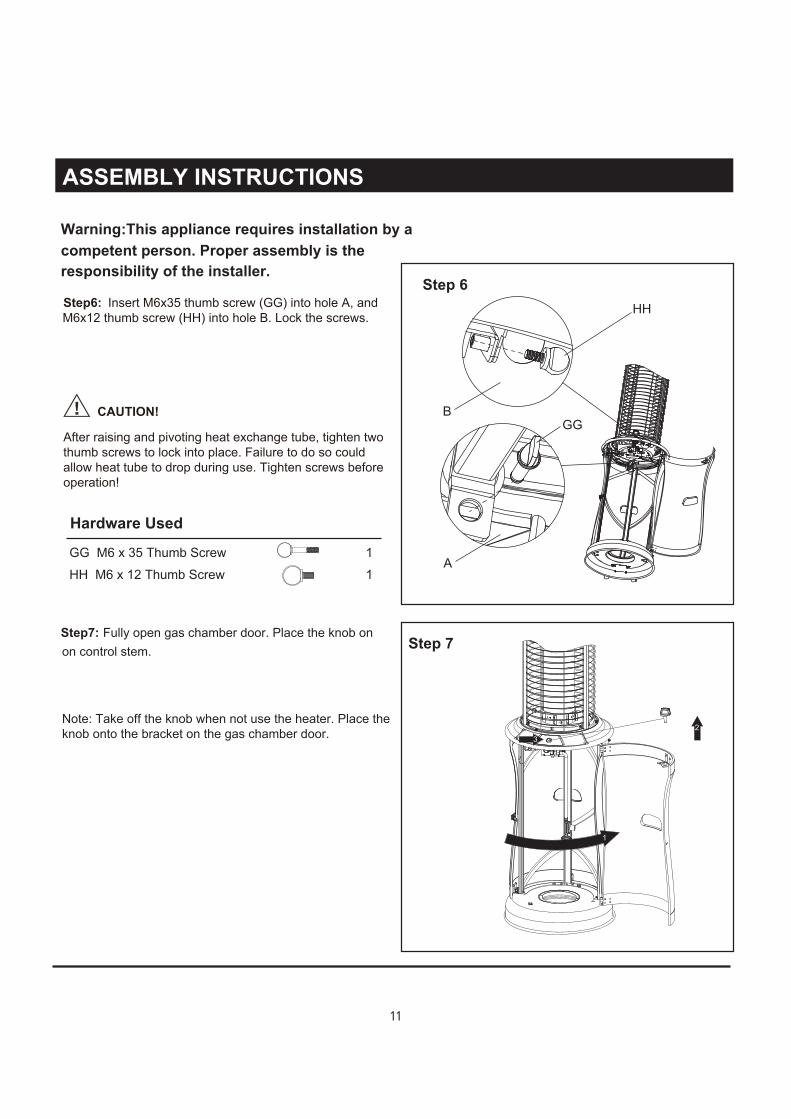
Step 7Step7: Fully open gas chamber door. Place the knob onon control stem.
Note: Take off the knob when not use the heater. Place theknob onto the bracket on the gas chamber door.
competent person. Proper assembly is the responsibility of the installer.
Step 6Step6:
CAUTION!
Insert M6x35 thumb screw (GG) into hole A, and M6x12 thumb screw (HH) into hole B. Lock the screws.
After raising and pivoting heat exchange tube, tighten two thumb screws to lock into place. Failure to do so could allow heat tube to drop during use. Tighten screws before operation!
Warning:This appliance requires installation by a
HH
GGB
AGG M6 x 35 Thumb ScrewHH M6 x 12 Thumb Screw
11
Hardware Used
23
1
11

ASSEMBLY INSTRUCTIONS
Step 8
Step 9
Step8: Place AA battery(1.5V) (not included) in compartment below control panel.
Warning:This appliance requires installationby a competent person. Proper assembly isthe responsibility of the installer.
Step9: Place the gas cylinder (not included) into the base assembly , and fix it with fixing chain. Attach the regulator to the cylinder, turn clockwise to tighten it securely, and then close the door.Note: Make sure to check for leaks once the cylinder has been replaced. (Refer to the “check for leaks” section on page 13)
Tighten
+-
12

SAFETY CHECK WARNING : ONLY AN AUTHORIZED GAS TECHNICIAN SHOULD INSTALL THIS PRODUCT.
Check for leaksAll connections on the patio heater have beenchecked for leakage at the factory. In transportation and handling some connectionsmay have loosened. Follow these steps to check the gas hose/regulator/cylinder connections:
2) Spoon or brush several drops (or use squirt bottle) of the solution onto hose connection, regulator & cylinder connection.
3) Turn on gas cylinder valve. Inspect the connections and look for bubbles.
4) If no bubbles appear, the connection is safe.
5) If bubbles appear, there is leakage. Loosen and re-tighten this connection. If connection still leaks, please call customer service: 1-866-814-0585.
Note:1) The cylinder supply system must be arranged for vapor withdrawal;
2) The cylinder used must include a collar to protect the cylinder valve.
The hose assembly must be replaced prior to the appliance being put into operation if there is evidence of excessive abrasion or wear, or if the hose is damaged.
At least once a year, a complete inspection of the entire gas path components should be performed. If there is need to replace parts, proceed to leak test after reassembly (These procedures should be performed by a professional technician).
regulator & cylinderconnection
1) Make leakage solution by mixing 1 part liquid dish soap and 3 parts water.
13
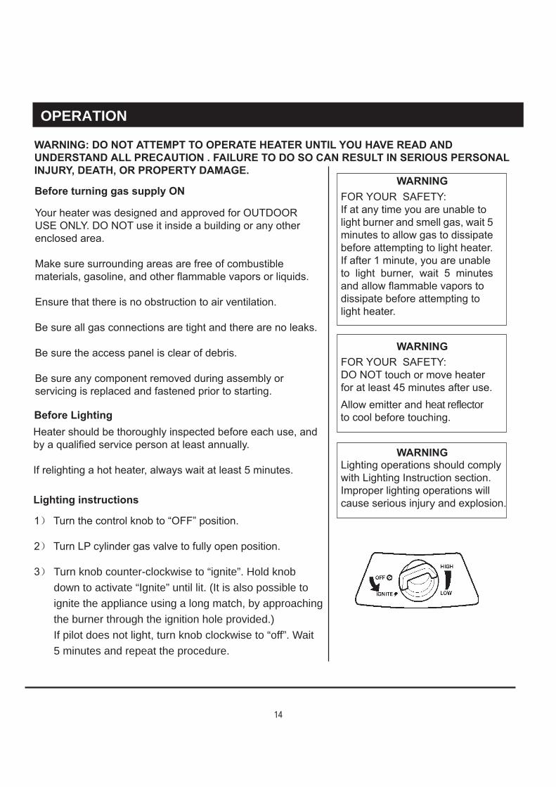
OPERATION
Turn knob counter-clockwise to “ignite”. Hold knobdown to activate “Ignite” until lit. (It is also possible to ignite the appliance using a long match, by approaching the burner through the ignition hole provided.)If pilot does not light, turn knob clockwise to “off”. Wait5 minutes and repeat the procedure.
y
heat reflector
14

OPERATION
4) When the pilot is lit keep knob pressed for up to 20 seconds to heat the thermocouple flame sensor, then release it (first ignition generally takes more time, because the gas circuit is full of air).5) If the pilot does not stay lit, repeat steps 3 and 4.6) Turn knob to “LOW “ position.7) Adjust the heat input by turning the knob from the “low “ position, to the “HIGH” position, as required.8) After lighting, turn knob from “LOW “ to “HIGH”, position and back, to check flame stability.9) In case of accidental break down of the flame (due to wind or other reasons), a Flame Safely Device (FSD) will automatically shut-off gas supply within 90 seconds.
If you experience any ignition problem consult the following “Troubleshooting”.These lighting instructions must be followed. An unsafe condition can occur if they are not followed correctly.
If black spot is accumulating on the emitter grid or reflector,the heater should be turned off immediately. The heater should not be operated again until the unit is serviced and or repaired.
Thermocouple Pilot Assembly
15

OPERATION
Emitter grid will become bright red due to intense heat. The color is more visible at night. Burner will display tongues of blue flame. These flames should not produce thick black smoke, indicating an obstruction of airflow through the burners.
16

LOCATING HEATER FOR USE
CAUTION: WHEN CERTAIN MATERIALS OR ITEMS ARE LEFT, ABOVE, BESIDE OR UNDERTHIS HEATER WHILE IN USE, THEY WILL BE SUBJECT TO RADIANT HEAT AND COULD BESERIOUSLY DAMAGED.
This heater is primarily used for the heating ofoutdoor patios, decks, spas, pools and openworking areas.
Always make sure that adequate fresh airventilation is provided. Follow the spacingtolerances shown in the following figure right atall times.
This heater must be placed on level, firm ground.
Never operate in an explosive atmosphere.Keep away from areas where gasoline or otherflammable liquids or vapors are stored or used.
17

MAINTENANCE/STORAGE
DO NOT touch or move heater forat least 45 minutes after use. Allowall burner elements to cool beforetouching.
FOR YOUR SAFETY ; WARNING:
NOTE:In a salt-air environment (such as near an ocean). corrosion occurs more quickly than normal. Frequently check for corroded areas and repair them promptly.
NOTE:wait until heater is cool before covering.
CLEANING AND MAINTENANCE : To enjoy years of outstanding performance from yourheater make sure you perform the following maintenanceactivities on a regular basis:
Keep exterior surfaces clean.Use warm soapy water for cleaning. Never useflammable of corrosive cleaning agents.While washing your unit, be sure to keep the areaaround the burner and pilot assembly dry at all times. Ifthe gas control is exposed to water in any way, do NOTtry to use it. It must be replaced.Keep the appliance area free and clean from combustiblematerials, gasoline and other flammable vapors andliquids; not obstructing the flow of combustion andventilation air; keeping the ventilation opening(s) of thecylinder enclosure free and clear from debris.
Gas odor with extreme yellow tipping of flame. Heater does NOT reach the desired temperature. Heater glow is excessively uneven. Heater makes popping noises.
Visually check burner flames.
Check if there are cracks or worn sections on hose. If yes, please call our customer service to replace hose.At least once a year, the unit should be inspected forthe presence of spiders, spider webs or other insects.Air flow must be unobstructed. Keep controls, burner,and circulating air passageways clean. Signs of possibleblockage include:
Check the cracks or worn sections
18

MAINTENANCE/STORAGE
NOTE:wait until heater is cool before covering.
Turn the control knob to "OFF" position.Turn LP cylinder to "OFF" position.Store heater upright in an area sheltered from directcontact with inclement weather (such as rain, sleet, hail, snow, dust and debris).If desired, cover heater to protect exterior surfaces and to help prevent build up in air passages.
Spiders and insects can nest in burner or orifices. This dangerous condition can damage heater and render it unsafe for use. Clean burner holes by using a heavy-dutypipe cleaner. Compressed air may help clear awaysmaller particles.Carbon deposits may create a fire hazard. Clean heat
STORAGE:Between uses:
During periods of extended inactivity or whentransporting;
Turn LP cylinder to "OFF" positionUnhook fixing chain.Disconnect the regulator from the LP Cylinder by turning counter-clockwise and move LP cylinder to a secure, well-ventilated
Remove 2pcs thumb screws. Remove knob from control panel and store in door. Keep gas chamber door partially open. Turn heat exchange tube clockwise. Slowly descend heat exchange tube.
Always remove the battery from the patio heater if not being used for long periods of time as battery leakage can cause corrosion in the battery ignition housing.
location outdoors. DO NOT store in a location that will exceed 125 degrees F.
Store heater upright in an area sheltered from directcontact with inclement weather (such as rain, sleet, hail, snow, dust and debris).
If desired, cover heater to protect exterior surfaces and to help prevent build up in air passages.
WARNING:Do NOT keep the heater fully extended and the heat exchange tube must be lowered down to position during transportation!
.
reflector and heat exchange tube with warm soapy water if any carbon deposits develop.
19

TROUBLESHOOTING
Fuel tank empty
The appliance has been manufactured under the highest standards of quality and workmanship. Wewarrant to the original consumer purchaser that all aspects of this product will be free of defects inmaterial and workmanship for one (1) year from the date of purchase. A replacement for any defectivepart will be supplied free of charge for installation by the consumer. Defects or damage caused by theuse of other than genuine parts are not covered by this warranty. This warranty shall be effective fromthe date of purchase as shown in the purchaser’s receipt.
ONE-YEAR LIMITED WARRANTY
This warranty is valid for the original consumer purchaser only and excludes product damage due toshipment or failure which results from alteration, product abuse, or product misuse, whether performedby a contractor, service company, or consumer. We will not be responsible for labor charges and/ordamage incurred in installation, repair or replacement, nor for incidental or consequential damage.
SHINERICH INDUSTRIAL LTD.Toll free No.:1-866-814-0585Addr.:8/F, Noble Center, 1006 Fuzhong 3rd. Rd,Futian District, Shenzhen, China
20