Wi n t r i s s Co n t r o l s Gr o u p , L L C 100 ... SFI_Manual.pdf · Changes for Revision E of...
77
Indramat Wintriss SFI ® ServoFeed Interface for: SmartPAC SmartPAC 2 ProCam 1500 DiPro 1500 1104500 Rev. E December 2014 Tech Support Hotline 800-586-8324 8-5 EST www.wintriss.com ® ® ® ® ® Wintriss Controls Group, LLC 100 Discovery Way Unit 110 Acton MA 01720 USA Phone (800) 586-8324 Fax (978) 263-2048 PRINTED IN USA DA46048
Transcript of Wi n t r i s s Co n t r o l s Gr o u p , L L C 100 ... SFI_Manual.pdf · Changes for Revision E of...
Indramat Wintriss SFI
®ServoFeed Interface for:
SmartPACSmartPAC 2ProCam 1500DiPro 1500
1104500Rev. E December 2014
Tech Support Hotline 800-586-8324 8-5 EST
www.wintriss.com
®
®
®
®
®
Wintriss Controls Group, LLC100 Discovery WayUnit 110Acton MA 01720 USAPhone (800) 586-8324Fax (978) 263-2048
PRINTED IN USA DA46048

Changes for Revision E of the
Indramat Wintriss SFI User Manual (1104500)
Revision E of the Indramat Wintriss SFI User Manual covers all Indramat SFI software versions.
The changes for Revision E include:
Added to the cover of the installation manual the URL and QR code user needs to download
the user manual
PROVIDE IMPORTANT INFO
DURING TROUBLESHOOTING WITH WINTRISS TECH SUPPORT!
Whenever you need to contact Wintriss Tech Support for technical assistance, be ready to provide some important information to help solve the problem. Please supply: product name (e.g. SmartPAC standard); installed options (e.g. SFI, etc.); and firmware version number (e.g. Vs. 2.00). You can determine the last two items by going into “Installed Options” in Initialization mode. You can also determine firmware version number from the labeled chip on the firmware board (see Figure 2-1, page 9, for location).

Thank you for purchasing a Wintriss Product. We appreciate your business and want to do whatever we can to ensure your satisfaction. Wintriss products are built to stay on the job day after day, and are backed by an ironclad guarantee, international standards approvals, and unbeatable support. Whenever you need assistance or service, we back all our products with excellent spare parts inventories, training programs, and prompt repair service. We would like to share with you a list of service options–probably the largest number of service options offered in the industry.
• Technical Assistance
We offer a toll-free line for technical assistance. Call our Wintriss Technical Support Hotline at 1-800-586-TECH (8324) should you have any questions about your equipment. Our technical staff is ready to assist you Monday through Friday, 8 a.m. to 5 p.m. EST. In many cases our experienced technical staff can resolve your inquiry right over the phone.
• Return Authorization
Please call our “800” number for a return authorization (RMA) number to return a product for repair. Returned goods must arrive freight prepaid. In order to process your return quickly, we ask that you provide us with the following pertinent information when you call: purchase order number, shipping address, contact name and telephone number, and product type. The assigned RMA number should appear on all packages returned to Wintriss Controls Group to ensure prompt service.
At the time of requesting an RMA, you will be quoted a flat-rate repair price for the product you are returning. We ask that you either fax us a PO for that amount or enclose the PO with the returned item. This will enable us to ship the item back to you as soon as the repair has been completed. If the item cannot be repaired or there are additional charges, you will be contacted for approval.
Please be sure to carefully pack all returned items and ship to our Acton, MA location.
• Expedited Repair Program
Rush service providing 48 hour turnaround is available for most products upon request. An Expedite Fee will be applied to our standard repair rate.
• Board Exchange Program
If your needs are urgent, you can take advantage of out Board Exchange (EX) program. Call our “800” number between 8 a.m. to 5 p.m. EST and we will send a replacement to you overnight. A fee does apply to this service. Contact Wintriss Technical Support at 800-586-8324 for details.
• Service Center
Our Service Center for product service is located at our headquarters in Acton, MA. If your equipment requires repair, please contact us at 800-586-8324 to obtain a return authorization number.
Nationwide field service is also available. Contact the Wintriss Technical Support group at 800-586-8324.
• Product Training
We also offer both product training and maintenance/troubleshooting courses at our Acton, MA and Chicago-area facilities. On-site training is available from the factory or through your local Wintriss representative.
• Restocking Charge
Returned goods are subject to a 20% restocking charge if returned for credit. The minimum charge is $50, not to exceed $250 per item.
Whatever the product, we are committed to satisfying you with innovative engineering, quality construction, reliable performance, and ongoing, helpful support. Call us whenever you need assistance.
Indramat Wintriss SFI User Manual 1104500 Table of Contents Page i
Table of Contents
Chapter 1 Indramat ServoFeed Interface (SFI) ...................................................... 1
About Wintriss ServoFeed Interfaces ................................................................................................................1 Indramat ServoFeed Interface............................................................................................................................2 Indramat SFI Operation .....................................................................................................................................3 Indramat SFI Features .......................................................................................................................................3 SmartPAC 2 and Original SmartPAC................................................................................................................4
Chapter 2 Indramat SFI Installation........................................................................ 7
Installing Indramat SFI in SmartPAC................................................................................................................8 Installing Indramat SFI Firmware in SmartPAC...........................................................................................8 Wiring the Indramat Feed Controller to SmartPAC....................................................................................10
Installing Indramat SFI in a 1500 Series Control ............................................................................................13 Installing Indramat SFI Firmware in a 1500 Series Control .......................................................................13 Wiring the Indramat Feed Controller to a 1500 Series Control ..................................................................17
Setting Communications Parameters at Indramat............................................................................................19 Setting Parameters on Indramat CLM Direct Connect Controls.................................................................19 Setting Parameters on Indramat CLM SOT “Old Style” Controls..............................................................20 Setting Parameters on Indramat CLM SOT “New Style” Controls ............................................................21 Setting Parameters on Indramat DKS Controls...........................................................................................21 Setting Parameters on Indramat ECO BTV04 and BTV06 Controls ..........................................................22 Setting Parameters on Indramat RFX Controls with VCP08 Displays .......................................................23
Chapter 3 Indramat SFI Initialization Mode.......................................................... 25
Initializing Indramat SFI in SmartPAC ...........................................................................................................25 Initialization Menu......................................................................................................................................26 Initializing Feed Control Parameters...........................................................................................................26 Security Access ...........................................................................................................................................28 Viewing Communications with the POSITION SENSOR Item .................................................................29
Initializing Indramat SFI in a 1500 Series Control ..........................................................................................31 Initialization Menu......................................................................................................................................31 Initializing Feed Control Parameters...........................................................................................................32 Security Access ...........................................................................................................................................33
Chapter 4 Indramat SFI Program Mode................................................................ 39
Using Indramat SFI Program Mode in SmartPAC ..........................................................................................39 About Tool Number ....................................................................................................................................39 Program Menu ............................................................................................................................................39 Feed Settings...............................................................................................................................................41 Feed Advisor...............................................................................................................................................41 Loading by Tool Number............................................................................................................................44

1104500 Indramat Wintriss SFI User Manual
Page ii Table of Contents
Using Indramat SFI Program Mode in a 1500 Series Control .........................................................................45 About Tool Number ....................................................................................................................................45 Program Menu.............................................................................................................................................45 Feed Settings ...............................................................................................................................................46 Feed Advisor ...............................................................................................................................................47 Loading by Tool Number............................................................................................................................49
Chapter 5 Indramat SFI Run Mode........................................................................51
Using Indramat SFI Run Mode in SmartPAC .................................................................................................51 About Tool Numbers...................................................................................................................................51 Run Menu....................................................................................................................................................52
Using Indramat SFI Run Mode in a 1500 Series Control ......................................................................................53 About Tool Numbers...................................................................................................................................53 Run Menu....................................................................................................................................................53
Chapter 6 Indramat SFI Troubleshooting.............................................................55
Troubleshooting in SmartPAC.........................................................................................................................55 Troubleshooting in a 1500 Series Control .......................................................................................................56
Index........................................................................................................................57
Wintriss User Manuals
Wiring Diagrams at End of Manual
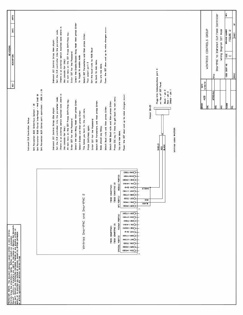
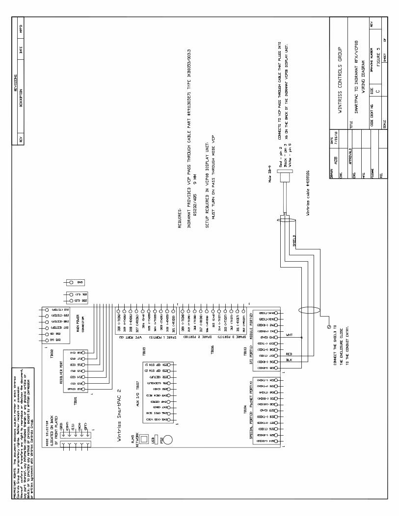
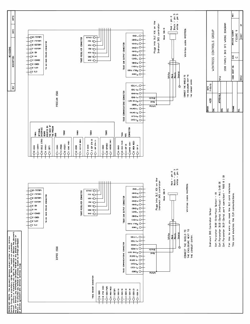
Figure 1 SmartPAC to Indramat CLM Feed Controller Direct Connect Mode Figure 2 SmartPAC to Indramat CLM Feed Controller SOT Mode Figure 3 SmartPAC to Indramat DKS Feed Controller Direct Connect Mode Figure 4 SmartPAC to Indramat ECO DB-15 Feed Controller Figure 5 SmartPAC to Indramat RFX/VCP08 Wiring Diagram Figure 6 SmartPAC Loopback Wiring Connections Figure 7 1500 Series Controls to CLM Feed Controller Direct Connect Mode Figure 8 1500 Series Controls to CLM Feed Controller SOT Mode Figure 9 1500 Series Controls to DKS Feed Controller Direct Connect Mode
List of Figures
Figure 1-1. Panel Displays, SmartPAC 2 and Original SmartPAC .......................................................................4 Figure 2-1. SmartPAC Processor Board: Location of Important Components......................................................9 Figure 2-2. Attaching Wires to a Phoenix Connector (6-Pin Connector Shown) ................................................12 Figure 2-3. ProCam 1500 Processor Board: Location of Important Components ...............................................14 Figure 2-4. DiPro 1500 Processor Board: Location of Important Components...................................................15 Figure 3-1. SmartPAC Main Initialization Menu with “FEED CONTROL” Selected ..........................................26 Figure 3-2. Feed Control Initialization Parameters Screen with “CONNECTION TYPE” Selected ..................27 Figure 3-3. SmartPAC Security Access Menu with Feed Adjustment Set for both Program and Run Modes ...............................................................................................................................................28 Figure 3-4. SmartPAC Security Access Menu with Feed Adjustment Set for Program Mode Only...................29

Indramat Wintriss SFI User Manual 1104500
Table of Contents Page iii
Figure 3-5. SmartPAC “Position Sensor” Display in Initialization Mode...........................................................29 Figure 3-6. SmartPAC Communication Data Viewer Screen..............................................................................30 Figure 3-7. SmartPAC Communication Transmit/Receive Screen .....................................................................30 Figure 3-8. 1500 Series Initialization Menu with “FEED PARAMETERS” Selected.............................................31 Figure 3-9. 1500 Series Feed Control Initialization Parameters Screen with “CONNECTION TYPE” Selected.............................................................................................................................................32 Figure 3-10. 1500 Series Security Access Menu with Feed Adjustment Set for both Program and Run Modes..............................................................................................................................................33 Figure 3-11. 1500 Series Security Access Menu with Feed Adjustment Set for Program Mode Only ...............34 Figure 3-12. DiPro 1500 Initialization Menu with “FEED PARAMETERS 2” Selected ...................................34 Figure 3-13. DiPro 1500 Feed Parameters 2 Initialization Screen with Feed Adjustment Set for both Program and Run Modes.................................................................................................................35 Figure 3-14. DiPro 1500 Feed Parameters 2 Initialization Screen with “ADV. CONST. CH 1” Selected. ........37 Figure 4-1. SmartPAC Main Programming Menu with “FEED CONTROL” Selected......................................40 Figure 4-2. SmartPAC Servo Feed Parameters Screen with Change Parameters Window .................................41 Figure 4-3. SmartPAC Servo Feed Advisor Screen with “FEED LENGTH” Selected.......................................42 Figure 4-4. SmartPAC Servo Feed Advisor Screen with “CALCULATE” Selected..........................................43 Figure 4-5. 1500 Series Program Menu with “SET FEED” Selected..................................................................45 Figure 4-6. 1500 Series Servo Feed Parameters Screen with “FEED LENGTH” Selected ................................46 Figure 4-7. 1500 Series Feed Length Screen.......................................................................................................46 Figure 4-8. 1500 Series Servo Feed Advisor Screen with “FEED LENGTH” Selected .....................................47 Figure 4-9. 1500 Series Servo Feed Advisor Screen with “CALCULATE” Selected ......................................48 Figure 5-1. SmartPAC Run Menu with “FEED CONTROL” Selected ..............................................................52 Figure 5-2. SmartPAC Feed Control Screen with “FEED LENGTH” Selected..................................................52 Figure 5-3. 1500 Series Run Menu with “ADJUST FEED” Selected .................................................................53 Figure 5-4. 1500 Series Adjust Feed Screen with “FEED LENGTH” Selected..................................................54 Figure 6-1. SmartPAC Communications Fault Message.....................................................................................55 Figure 6-2. 1500 Series Communications Fault Message ...................................................................................56
List of Tables
Table 2-1. Cable Specifications for Indramat Servofeeds ...................................................................................11 Table 2-2. Location of RS-232 Connector on Indramat Servofeed Controllers ..................................................11 Table 2-3. Cable Specifications for Indramat Servofeeds ...................................................................................17 Table 2-4. Location of RS-232 Connector on Indramat Servofeed Controllers ..................................................18 Table 2-5. Indramat CLM Direct Connect Communications Settings.................................................................19 Table 2-6. Indramat CLM SOT Communications Settings .................................................................................20 Table 2-7. Indramat DKS Communications Settings ..........................................................................................21 Table 2-8. Indramat ECO BTV04 Communications Settings .............................................................................22 Table 2-9. Indramat ECO BTV06 Communications Settings .............................................................................23
1104500 Indramat Wintriss SFI User Manual
Page iv Table of Contents
How To Use This Manual
This manual shows you how to install and operate the Indramat ServoFeed Interface (SFI) on SmartPAC and Wintriss 1500 series controls. The following Indramat servofeeds are documented:
• CLM Direct Connect • CLM SOT • DKS • ECO with BTV04 and BTV06 terminals • RFX with VCP08 terminal (SmartPAC 2 only)
NOTICE FOLLOW INSTRUCTIONS FOR YOUR SPECIFIC INDRAMAT MODEL
Instructions in this manual may pertain to a single Indramat servofeed model or to multiple servofeed models. Make sure to follow the directions that pertain to your specific Indramat unit.
Chapter 1 introduces you to the Indramat ServoFeed Interface (SFI). It provides an overview of Wintriss SFIs in general and the Indramat SFI in particular and describes briefly Indramat SFI operation and features.
Chapter 2 shows you how to install Indramat SFI on SmartPAC and Wintriss 1500 series controls. The chapter covers installation of SFI firmware, wiring of Indramat feed controllers to the appropriate Wintriss product, and setting of communications parameters at the Indramat controller. Wiring diagrams for each Indramat model are provided at the back of the manual.
Chapters 3 through 5 show you how to use Indramat SFI in all three SmartPAC and 1500 series operating modes – Initialization (covered in Chapter 3), Program (Chapter 4), and Run (Chapter 5). If you need more detail about Indramat SFI operation than is provided in these chapters, refer to your Indramat servofeed manual.
Chapter 6 shows you how to troubleshoot communications interruptions between your Indramat servofeed and the applicable Wintriss control. For Indramat error conditions specific to the feed controller, consult your Indramat servofeed user manual.
NOTICE INDRAMAT SFI AND SMARTPAC 2
You can use Indramat SFI with SmartPAC 2 as well as with the original SmartPAC. Instructions provided in this manual that are specific to SmartPAC pertain to both SmartPAC 1 and SmartPAC 2 (refer to “SmartPAC 2 and Original SmartPAC,” page 4, for more information). Wiring diagrams at the back of the manual show pin connections for both SmartPACs.

Indramat Wintriss SFI User Manual 1104500
Table of Contents Page v
Warranty
Wintriss Controls warrants that Wintriss electronic controls are free from defects in
material and workmanship under normal use and service for a period of one year (two
years for Shadow light curtains) from date of shipment. All software products
(LETS/SFC and SBR), electro-mechanical assemblies, and sensors are warranted to be
free from defects in material and workmanship under normal use and service for a period
of 90 days from date of shipment. Wintriss’s obligations under this warranty are limited
to repairing or replacing, at its discretion and at its factory or facility, any products which
shall, within the applicable period after shipment, be returned to Wintriss Controls
freight prepaid, and which are, after examination, disclosed to the satisfaction of
Wintriss to be defective. This warranty shall not apply to any equipment which has
been subjected to improper installation, misuse, misapplication, negligence, accident,
or unauthorized modification. The provisions of this warranty do not extend the
original warranty of any product which has either been repaired or replaced by
Wintriss Controls. No other warranty is expressed or implied. Wintriss accepts no
liability for damages, including any anticipated or lost profits, incidental damages,
consequential damages, costs, time charges, or other losses incurred in connection
with the purchase, installation, repair or operation of our products, or any part thereof.
Please note:
It is solely the user’s responsibility to properly install and maintain Wintriss controls
and equipment. Wintriss Controls manufactures its products to meet stringent
specifications and cannot assume responsibility for consequences arising from their
misuse.
Wintriss Controls Group, LLC INDRAMAT WINTRISS SFI 100 Discovery Way USER MANUAL Unit 110 1104500 Acton, MA 01720 ©2014 Wintriss Controls Group, LLC Telephone: (800) 586-TECH (8324) (978) 268-2700 Fax: (978) 263-2048 Internet: http://www.wintriss.com

1104500 Indramat Wintriss SFI User Manual
Page vi Table of Contents

Indramat Wintriss SFI User Manual 1104500 Introduction Chapter 1 Page 1
Chapter 1 Indramat ServoFeed Interface (SFI)
About Wintriss ServoFeed Interfaces
ServoFeed Interface (SFI) is an option available with the following Wintriss products – SmartPAC 1, SmartPAC 2, ProCam 1500, and DiPro 1500 with Cam – allowing these controls to be interfaced with most servo-driven feeds.
Composed of both hardware and software, SFI can be integrated with an existing system or ordered with a new one. SFI enables the microprocessor-based Wintriss product to be “interfaced” with the servofeed controller, allowing feed settings for the tool to be stored in tool number memory at the Wintriss control. The Wintriss control will automatically transmit the settings to the servofeed every time a tool is changed. Typically, there is only one operator interface, or control panel, to use and only one tool number to load when setting a die. With some feeds, the Wintriss product becomes the feed’s panel. With other feeds, the feed panel remains functional but may be rarely, if ever, used.
Although SFI is similar from one feed to the next, there are differences that are feed-manufacturer- or feed-controller-specific. Some feeds will not accept certain information via a communications port; in others the controller only communicates during certain modes. This may be a controller issue, or a decision on the part of the feed manufacturer. SFI cannot change the way in which the feed controller operates but can only “talk/work” within the controller’s communications capabilities or as requested by the feed manufacturer. Nevertheless, SFI works like the Wintriss product within which it is installed, using similar menus and expected key strokes to program, adjust, and load feed settings.
To use the ServoFeed Interface, you must install the appropriate firmware chip in your Wintriss control. Then you simply connect the unit to your servofeed, using a cable that plugs into your servofeed’s RS-232 port. See Chapter 2 for installation instructions for the appropriate product.

1104500 Indramat Wintriss SFI User Manual
Page 2 Chapter 1 Introduction
Indramat ServoFeed Interface
The Indramat ServoFeed Interface allows several user-defined choices as well as feed adjustments while running. It also includes “Feed Advisor,” a program that helps you determine the optimum, or slowest, feed speed for your feed setup. You program the parameters (press speed, feed arc/degrees available to feed, and length), and Feed Advisor calculates the feed speed. If a feed speed cannot be calculated from the values you supply, Feed Advisor will offer a suggested solution.
With Indramat SFI, the feed is set and its parameters stored at the Wintriss control. There are three modes: Initialization, Program, and Run/Adjust. Depending on the Wintriss control and specific SFI, screen headings within these modes may vary slightly. However, the features are similar.
In Initialization mode, you set the major servofeed parameters, configuring how the SFI works. In Initialization mode, you set the connection type, determine the system’s security, verify communications between the Indramat control and your Wintriss product, and configure cam “auto advance” parameters. See Chapter 3 for more information about Initialization mode.
In Program mode, you program a tool number, make major changes to a setup, and load the tool number that you want to run. You can also use the Feed Advisor. See Chapter 4 for more information about Program mode.
In Run or Adjust mode, you can load a tool number and fine-tune the parameters set for it – if allowed by your security settings (Initialization Mode). See Chapter 5 for more information about Run mode.
NOTICE REFER TO THE APPROPRIATE WINTRISS USER MANUAL
If you need additional help with any of the Wintriss products documented here, consult the appropriate Wintriss user manual, which explains in detail how to use all of the operating modes mentioned above as well as use of the keypad:
SmartPAC: #1100500 SmartPAC with WPC: #1101000 SmartPAC 2: #1126700 SmartPAC 2 with WPC: #1126800 SmartPAC 2 with WPC 2000: #1128600 ProCam 1500: 1095000 DiPro 1500: 1092000
Indramat Wintriss SFI User Manual 1104500
Introduction Chapter 1 Page 3
Indramat SFI Operation
Your Indramat Servofeed Interface (SFI) is actually an RS-232 interface, which consists not only of cable and connectors but also of specific circuit requirements and software instructions to transmit signals and data between your servofeed and the appropriate Wintriss control. Transmission of data is handled by software in the Wintriss product and by the software built into your servofeed. Your servofeed came with all the RS-232 circuitry and software already in place.
Wintriss worked with your servofeed manufacturer to design the proper hardware and software to automatically interface with your Indramat servofeed. As a result, all you have to do is install the firmware chip and connect a cable from the Wintriss control to your servofeed’s RS-232 port. Everything else is automatic. You can then make SFI settings at the keypad on the Wintriss product just as you would if you were using the interface on the servofeed itself.
Indramat SFI Features
NOTICE Features vary on different model Indramat feed controllers.
Using the Wintriss control menus in Indramat SFI, you can:
• Set various feed parameters (e.g., feed length, feed rate %) for your servofeed • Save feed settings under a specified tool number and recall them automatically when
you load setups by tool number • Modify or change setups • Use Feed Advisor to check your settings. If you key in feed angle and press speed,
Feed Advisor informs you if your settings are right for that job. • Adjust feed length and feed rate % while the press is running • Lock SFI settings in Adjust Mode to prevent unauthorized tampering
NOTICE REFER TO YOUR INDRAMAT SERVOFEED USER MANUAL!
For more detailed information about your Indramat servofeed controller, refer to the Indramat servofeed user manual.

1104500 Indramat Wintriss SFI User Manual
Page 4 Chapter 1 Introduction
SmartPAC 2 and Original SmartPAC
Your Indramat Servofeed Interface (SFI) can be used with either the original SmartPAC or SmartPAC 2. This manual covers Indramat SFI installation and operation for SmartPAC 1, but you can also use the manual to install and operate Indramat SFI on SmartPAC 2.
To install Indramat SFI on SmartPAC 2, follow the instructions in Chapter 2, referring to the appropriate wiring diagrams at the end of the manual. (Wiring diagrams show connections for both SmartPAC 1 and SmartPAC 2.) For Indramat SFI operation with SmartPAC 2, follow the instructions in chapters 3-6.
Indramat SFI menu organization in SmartPAC 2 is similar to that in SmartPAC 1, and Indramat SFI screens are virtually the same in both SmartPACs. As a result, you can refer to the screens and follow the steps provided in chapters 3-6 of this manual to initialize, program, run, and troubleshoot Indramat SFI in both SmartPAC 1 and SmartPAC 2. The main difference between the two SmartPACs is in their panel displays, as shown in Figure 1-1.
1
4
7
2 3
5 6
8 9
0 .CLEAR
Contrast
CURSOR
INTERRUPTEDSTROKE
BRAKEWARNING
ENTER
RESET
F1
F2
F3
F4
F5
F6
Wintriss Press Automation ControlSmartPAC
PROG RUN
ENABLE SENSORSCOUNTERSDIE PROTECTIONCAM SWITCHTOOL INFORMATIONRAM POSITIONRAM TONNAGEERROR LOGLOAD NEW TOOL
USE THE CURSOR KEYSTO MAKE SELECTIONS.PRESS ENTER TOACCESS SELECTION
TOOL NUMBER 6160 PART CNTR 0CHAIR BRACKET
ENABLE SENSORS
ENTER
RESET
PROG RUN
OFF
INCH
SINGLESTROKE
CONT
POWER
BRAKEWARNING
HELP
1 2 3
4 5 6
987
.0CLEAR
SmartPAC 2F1
F2
F3
F4
F5
F6
F7
F8
PRESS # 14TOOL NUMBER 6160 PART CNTR 0ANGLE BRACKET TWO HAND S.S.
PRESS ANGLE 330
CAMBIEAL ESPANOL
USE THE CURSOR KEYS ENABLE SENSORSTO MAKE SELECTIONS. COUNTERSPRESS ENTER TO CAM SWITCHACCESS SELECTION. BRAKE MONITOR
TONNAGE/WAVEFORMPROCESS MONITORFEED CONTROLPM MONITORTOOL INFORMATIONSHUTHGT/CNTRBALERROR LOGLOAD NEW TOOLDIALOG MENUTOGGLE HOT KEYS 1
330
Crank angle/SPM display
8 Function keys 6 Function keys
Help keySmartPAC 2
only
Contrast keysoriginal SmartPAC
only
SmartPAC 2 Original SmartPAC
Figure 1-1. Panel Displays, SmartPAC 2 and Original SmartPAC
SmartPAC 1 and SmartPAC 2 panel displays use a different number of function, or “F,” keys. SmartPAC 2 has eight function keys, and the original SmartPAC only six. Be sure to read the instructions on the display and the descriptive labels next to the function keys before you press an “F” key.

Indramat Wintriss SFI User Manual 1104500
Introduction Chapter 1 Page 5
NOTICE On many SmartPAC 2 screens, you can press the HELP key (see Figure 1-1) to display
instructions showing you how to use the screen.
If you need additional help using Indramat SFI with SmartPAC 2, refer to the appropriate SmartPAC 2 user manual:
• SmartPAC 2 (1126700) • SmartPAC 2 with WPC (1126800) • SmartPAC 2 with WPC 2000 (1128600)

1104500 Indramat Wintriss SFI User Manual
Page 6 Chapter 1 Introduction
Indramat Wintriss SFI User Manual 1104500 Indramat SFI Installation Chapter 2 Page 7
Chapter 2 Indramat SFI Installation
This chapter shows you how to install the components that allow your SmartPAC or Wintriss 1500 series control to operate your Indramat servofeed. The chapter provides instructions for installing SFI firmware in the applicable Wintriss control, making wiring connections between the Indramat servofeed controller and the Wintriss control, and setting communications parameters at the Indramat controller.
Wiring diagrams are provided at the back of the manual.
NOTICE INDRAMAT SFI AND SMARTPAC 2
You can use Indramat SFI with SmartPAC 2 as well as with the original SmartPAC. Instructions provided in this manual that are specific to SmartPAC pertain to both SmartPAC 1 and SmartPAC 2 (refer to “SmartPAC 2 and Original SmartPAC,” page 4, for more information). Wiring diagrams at the back of the manual show pin connections for both SmartPACs.
If you need further help in installing firmware or wiring your Wintriss control, consult the applicable Wintriss user manual.
NOTICE FOLLOW INSTRUCTIONS FOR YOUR SPECIFIC INDRAMAT MODEL
Four Indramat feed controllers are covered in this manual:
• CLM Direct Connect Mode • CLM SOT Mode • DKS • ECO with BTV04 and BTV06 terminals • RFX with VCP08 terminal (SmartPAC 2 only)
Make sure to follow the directions that pertain to your specific Indramat unit.

1104500 Indramat Wintriss SFI User Manual
Page 8 Chapter 2 Indramat SFI Installation
Installing Indramat SFI in SmartPAC
This section shows you how to install Indramat SFI in a SmartPAC control. Before starting, make sure you have the following parts:
• SFI firmware (unless factory-installed at time of order) • 20-foot 2-conductor (CLM models) or 3-conductor (DKS, ECO, and RFX) shielded
cable with one of the following types of DB connector attached at one end: male DB-25 (CLM Direct Connect), female DB-25 (CLM SOT), male DB-9 (DKS and RFX), or male DB-15 (ECO).
• 10-pin Phoenix connector
Installing Indramat SFI Firmware in SmartPAC
NOTICE For instructions on how to install upgraded firmware for Indramat SFI in SmartPAC 2, refer to
Appendix B, “Updating SmartPAC 2 Firmware,” in the SmartPAC 2 user manual.
To install upgraded firmware for Indramat SFI ServoFeed Interface capability in SmartPAC, perform these steps:
WARNING! ELECTRIC SHOCK HAZARD
• Ensure that the power source is off before you replace electronic components in a control.
• Disconnect power from the machinery it is connected to before replacing electronic components. This includes disconnecting power to the machine control and motor.
• Ensure that servicing is performed by qualified personnel.
Failure to comply with these instructions could result in death or serious injury.
1. Turn power off to SmartPAC. The display on the front panel should be blank and the Angle/RPM display should be unlit.
CAUTION DAMAGE TO BOARD FROM STATIC DISCHARGE
Ground yourself before touching circuit boards or chips by touching a large metal object such as the press. Static electricity can destroy electronic components.
Failure to comply with these instructions could result in property damage.
2. Making sure that you are grounded, open the SmartPAC enclosure and find the SmartPAC firmware board, which is located in the lower left corner of the SmartPAC processor board (see Figure 2-1, next page).

Indramat Wintriss SFI User Manual 1104500
Indramat SFI Installation Chapter 2 Page 9
Power TB101
ProCamPAC
socket
DiProPAC
socket
TB106 Resolver
PositionSensorTB107
Ribbon cableconnector
Firmware board
Firmware chip(with label)
Communications TB103
RAM chipor socket
SFI andAutoSetPAC
TB102
Figure 2-1. SmartPAC Processor Board: Location of Important Components
3. Remove the four screws holding the firmware board to the standoffs on the SmartPAC processor board, and put them aside.
4. Unplug the old SmartPAC firmware board from the SmartPAC processor board and put it where it will not be confused with the new SmartPAC firmware board.
NOTICE The white label on the firmware chip on the SmartPAC firmware board (see Figure 2-1)
provides SmartPAC firmware identification information, including version number.
5. Remove the new SmartPAC firmware board from its package and plug it into the SmartPAC processor board so that the RAM and firmware chips are at the bottom, as shown in Figure 2-1.

1104500 Indramat Wintriss SFI User Manual
Page 10 Chapter 2 Indramat SFI Installation
NOTICE Make sure to install the new SmartPAC firmware board with the correct orientation;
otherwise, the board will not plug into its socket.
6. Screw the four corners of the board into the standoffs on the SmartPAC processor board.
7. Turn on power to the SmartPAC unit and wait for either the Program or Run screen to appear on the display. If one of these screens displays clearly, the control is operating properly and you can proceed with wiring your Indramat servofeed, which is described in the next section.
If the unit powers up with a garbled display, turn the power off and check to make sure that the board is properly seated.
NOTICE Some firmware upgrades cause SmartPAC to generate a tool number checksum error the first
time you try to reload tool setups. If you get a checksum error after installing a new firmware board, enter Program mode and change one of the counters for that tool. Then reload the tool. If the unit still malfunctions, contact Wintriss Tech Support.
Wiring the Indramat Feed Controller to SmartPAC
NOTICE WIRING FOR YOUR SPECIFIC INDRAMAT FEED MODEL
Make sure to use the correct cable and wire it to the correct location on the controller for your specific Indramat servofeed model, referring to Tables 2-1 and 2-2, below, and to the appropriate wiring diagram (Figures 1-5) at the back of the manual. For additional information, consult your Indramat feed controller manual.
The Indramat RFX servofeed with VCP08 terminal is used only with SmartPAC 2 controls.
Be sure you have verified that SmartPAC is working properly before you proceed.
WARNING! ELECTRIC SHOCK HAZARD
• Ensure that the power source is off before you touch any wiring inside the enclosure.
• Disconnect power from the machinery it is connected to before making any wiring connections. This includes disconnecting power to the machine control and motor.
• Ensure that servicing is performed by qualified personnel.
Failure to comply with these instructions could result in death or serious injury.
To make wiring connections between your Indramat feed controller and SmartPAC, perform the following steps, referring to Figures 1-5 at the end of the manual for specific pin connections:
1. Verify that SmartPAC and your feed are still turned off.
Indramat Wintriss SFI User Manual 1104500
Indramat SFI Installation Chapter 2 Page 11
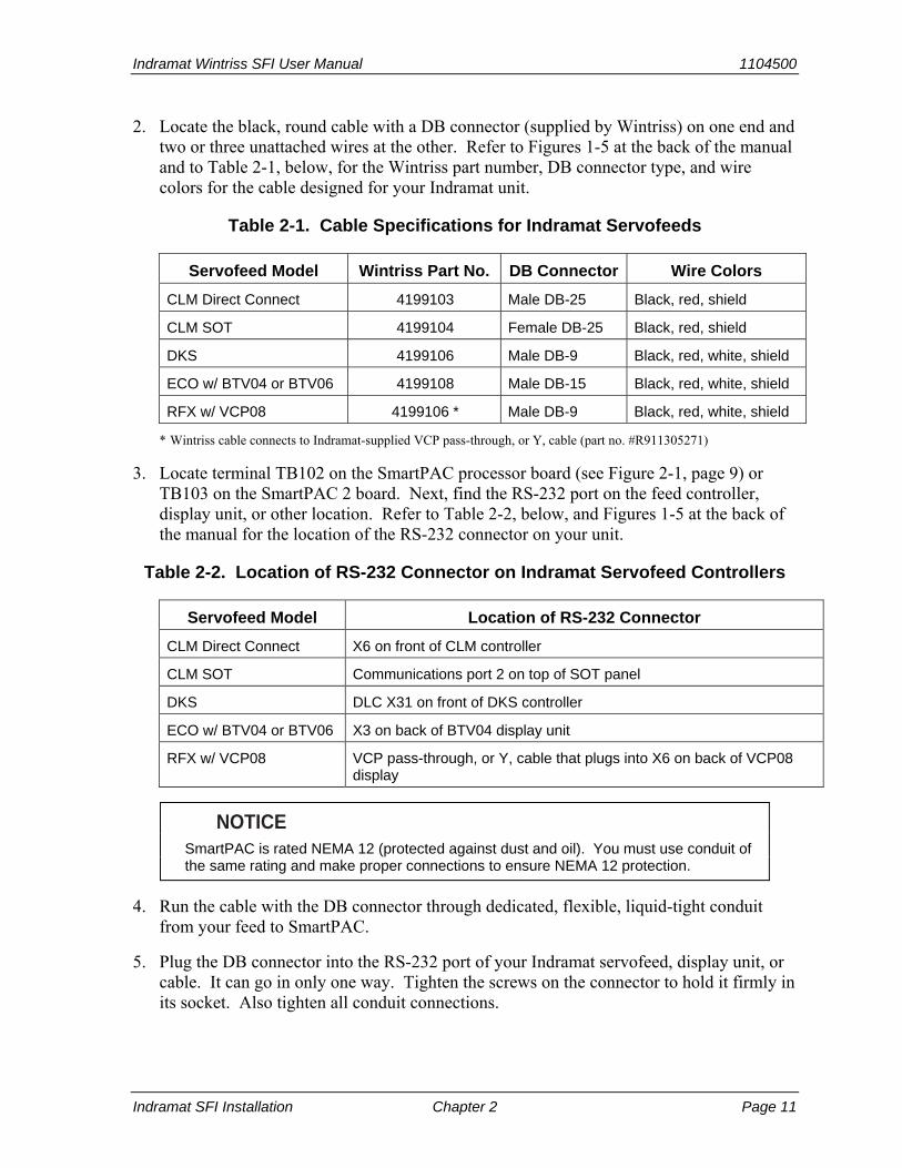
2. Locate the black, round cable with a DB connector (supplied by Wintriss) on one end and two or three unattached wires at the other. Refer to Figures 1-5 at the back of the manual and to Table 2-1, below, for the Wintriss part number, DB connector type, and wire colors for the cable designed for your Indramat unit.
Table 2-1. Cable Specifications for Indramat Servofeeds
Servofeed Model Wintriss Part No. DB Connector Wire Colors
CLM Direct Connect 4199103 Male DB-25 Black, red, shield
CLM SOT 4199104 Female DB-25 Black, red, shield
DKS 4199106 Male DB-9 Black, red, white, shield
ECO w/ BTV04 or BTV06 4199108 Male DB-15 Black, red, white, shield
RFX w/ VCP08 4199106 * Male DB-9 Black, red, white, shield
* Wintriss cable connects to Indramat-supplied VCP pass-through, or Y, cable (part no. #R911305271)
3. Locate terminal TB102 on the SmartPAC processor board (see Figure 2-1, page 9) or TB103 on the SmartPAC 2 board. Next, find the RS-232 port on the feed controller, display unit, or other location. Refer to Table 2-2, below, and Figures 1-5 at the back of the manual for the location of the RS-232 connector on your unit.
Table 2-2. Location of RS-232 Connector on Indramat Servofeed Controllers
Servofeed Model Location of RS-232 Connector
CLM Direct Connect X6 on front of CLM controller
CLM SOT Communications port 2 on top of SOT panel
DKS DLC X31 on front of DKS controller
ECO w/ BTV04 or BTV06 X3 on back of BTV04 display unit
RFX w/ VCP08 VCP pass-through, or Y, cable that plugs into X6 on back of VCP08 display
NOTICE SmartPAC is rated NEMA 12 (protected against dust and oil). You must use conduit of
the same rating and make proper connections to ensure NEMA 12 protection.
4. Run the cable with the DB connector through dedicated, flexible, liquid-tight conduit from your feed to SmartPAC.
5. Plug the DB connector into the RS-232 port of your Indramat servofeed, display unit, or cable. It can go in only one way. Tighten the screws on the connector to hold it firmly in its socket. Also tighten all conduit connections.
1104500 Indramat Wintriss SFI User Manual
Page 12 Chapter 2 Indramat SFI Installation
6. At SmartPAC, cut off any extra cable (a 1-foot service loop is recommended), and carefully remove the outer insulation and inner shielding on the cable in order to expose the wires. Strip insulation back 1/4” on each wire.
7. Connect the black and red (CLM models) or black, red, and white (DKS, ECO, or RFX models) wires at the SmartPAC end of the cable to the 10-pin Phoenix connector that plugs into the SmartPAC processor board (TB102 on SmartPAC 1, TB103 on SmartPAC 2). Refer to Figures 1-5 at the back of the manual for specific wiring connections for your Indramat servofeed model.
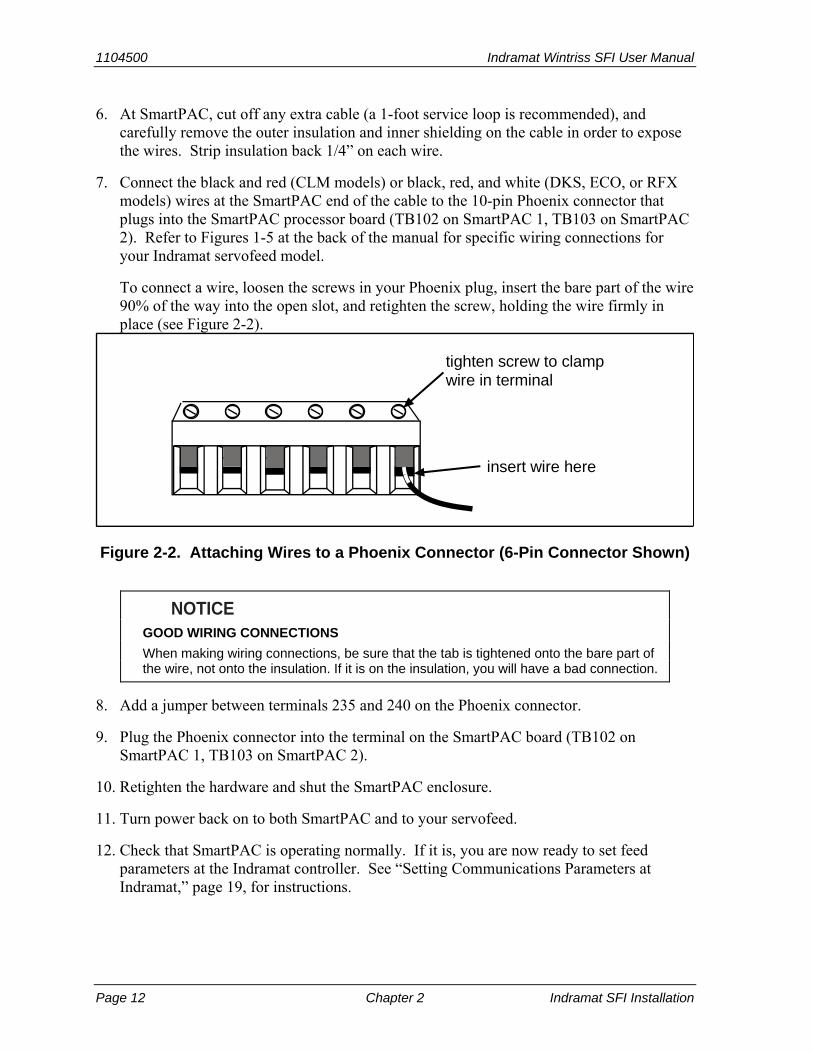
To connect a wire, loosen the screws in your Phoenix plug, insert the bare part of the wire 90% of the way into the open slot, and retighten the screw, holding the wire firmly in place (see Figure 2-2).
insert wire here
tighten screw to clampwire in terminal
Figure 2-2. Attaching Wires to a Phoenix Connector (6-Pin Connector Shown)
NOTICE GOOD WIRING CONNECTIONS
When making wiring connections, be sure that the tab is tightened onto the bare part of the wire, not onto the insulation. If it is on the insulation, you will have a bad connection.
8. Add a jumper between terminals 235 and 240 on the Phoenix connector.
9. Plug the Phoenix connector into the terminal on the SmartPAC board (TB102 on SmartPAC 1, TB103 on SmartPAC 2).
10. Retighten the hardware and shut the SmartPAC enclosure.
11. Turn power back on to both SmartPAC and to your servofeed.
12. Check that SmartPAC is operating normally. If it is, you are now ready to set feed parameters at the Indramat controller. See “Setting Communications Parameters at Indramat,” page 19, for instructions.
Indramat Wintriss SFI User Manual 1104500
Indramat SFI Installation Chapter 2 Page 13
NOTICE If SmartPAC powers up with a garbled display, turn the power off and recheck how you
installed your firmware. Review “Installing Indramat SFI Firmware in SmartPAC,” page 8. If the unit is still malfunctioning and you cannot find the reason for the problem, call Wintriss Tech Support for assistance.
Installing Indramat SFI in a 1500 Series Control
This section shows you how to install Indramat SFI in a Wintriss 1500 series control (i.e., ProCam 1500 or DiPro 1500). Before starting, make sure you have the following parts:
• SFI firmware (unless factory-installed at time of order) • 20-foot 2-conductor (CLM models) or 3-conductor (DKS) shielded cable with one of
the following types of DB connector attached at one end: male DB-25 (CLM Direct Connect), female DB-25 (CLM SOT), or male DB-9 (DKS).
• 10-pin Phoenix connector
Installing Indramat SFI Firmware in a 1500 Series Control
To install upgraded firmware for Indramat SFI ServoFeed Interface capability in a Wintriss 1500 series control, perform these steps:
WARNING! ELECTRIC SHOCK HAZARD
• Ensure that the power source is off before you replace electronic components in a control.
• Disconnect power from the machinery it is connected to before replacing electronic components. This includes disconnecting power to the machine control and motor.
• Ensure that servicing is performed by qualified personnel.
Failure to comply with these instructions could result in death or serious injury.
1. Turn off power to the 1500 control. The LCD on the front panel should be blank and the Angle/RPM display should be unlit.
CAUTION Ground yourself before touching circuit boards or chips by touching a large metal object
such as the press. Static electricity can destroy electronic components.
Failure to comply with these instructions could result in damage to the electronics.
2. Making sure that you are grounded, open the 1500 enclosure and find the firmware chip on the processor board (see Figure 2-3, next page, for chip location on the ProCam 1500 processor board and Figure 2-4, page 15, for chip location on the DiPro 1500 processor board). Note the orientation of the notch on the chip.

1104500 Indramat Wintriss SFI User Manual
Page 14 Chapter 2 Indramat SFI Installation
NOTICE The new firmware chip must be installed with the notch in the same orientation as the
old firmware chip.
• On the ProCam 1500 processor board, the notch on the firmware chip must face up.
• On the DiPro 1500 processor board, the notch on the firmware chip must face down.
Power TB104
RAM
Chip
TB106 Resolver
TB101
Communications TB103Cam Output TB102
Firmwarechip
(with label)
Figure 2-3. ProCam 1500 Processor Board: Location of Important Components
(Back Side of Panel Mount)

Indramat Wintriss SFI User Manual 1104500
Indramat SFI Installation Chapter 2 Page 15
Power TB104
RAM
Chip
TB106 Resolver
Ribbon cableconnector
Communications TB103 Cam Output TB102
Firmwarechip
(with label)
DiPro InputTB101
Figure 2-4. DiPro 1500 Processor Board: Location of Important Components

1104500 Indramat Wintriss SFI User Manual
Page 16 Chapter 2 Indramat SFI Installation
CAUTION DAMAGE TO PC BOARD
Insert the screwdriver between the chip and the socket. Be careful not to insert the screwdriver under the socket. You may damage the board.
Failure to comply with these instructions could result in property damage.
3. Insert a small screwdriver between the bottom of the firmware chip and its socket and carefully pry the old chip from the board. Put the old chip aside so that it will not be confused with the new firmware chip.
NOTICE The white label on the firmware chip provides ProCam 1500 (see Figure 2-3) or DiPro
1500 (see Figure 2-4) firmware identification information, including version number.
4. Open the package containing the new firmware chip and remove the chip from its holder.
CAUTION WRONG INSTALLATION DAMAGES CHIP
Install the chip with the notch facing the same direction as the notch on the chip you just removed; otherwise, when you power up the control, the chip will be destroyed.
• On the ProCam 1500 processor board, the notch on the firmware chip must face up.
• On the DiPro 1500 processor board, the notch on the firmware chip must face down.
Failure to comply with these instructions could result in property damage.
5. Plug the chip into the firmware socket, inserting the left row of pins first, then aligning the right row of pins over the socket and pushing them in. Make sure that the notch in the chip faces in the correct direction (i.e., up for ProCam 1500, down for DiPro 1500) and that all of the pins are in the socket.
NOTICE If the two rows of pins are spread too far apart to plug easily into the socket, hold the
chip on its side on a flat surface with the pins pointing toward you.
Being careful not to overbend the pins, gently draw the top of the chip toward you until the pins bend a little. Turn the chip over so that the other row of pins is now flat and pointing toward you. Draw the top of the chip toward you again until the pins bend.
When the rows of pins look parallel, plug the chip into its socket again. If the chip still doesn’t fit, repeat this procedure.
6. Turn on power to the 1500 unit and wait for either the Program or Run screen to display on the LCD. If one of these screens displays clearly, the control is operating properly and you can proceed with wiring your Indramat servofeed, which is described in the next section.

Indramat Wintriss SFI User Manual 1104500
Indramat SFI Installation Chapter 2 Page 17
If the unit powers up with a garbled display, one or more pins may be bent or not plugged in properly. To correct this problem, turn the power off and repeat the procedure described in the Notice for step 5. If the unit continues to malfunction, call Wintriss Tech Support.
Wiring the Indramat Feed Controller to a 1500 Series Control
NOTICE WIRING FOR YOUR SPECIFIC INDRAMAT FEED MODEL
Make sure to use the correct cable and wire it to the correct location on the controller for your specific Indramat servofeed model, referring to Tables 2-3 and 2-4, below, and to the appropriate wiring diagram (Figures 7-9) at the back of the manual. For additional information, consult your Indramat feed controller manual.
NOTICE Indramat ECO and RFX/VCP08 servofeeds cannot be used with 1500 series controls.
Be sure you have verified that your 1500 control is working properly before you proceed.
To make wiring connections between an Indramat feed controller and a Wintriss 1500 series control, perform the following steps, referring to Figures 7-9 at the end of the manual for specific pin connections:
1. Verify that the 1500 series control and your feed are still turned off.
2. Locate the black, round cable with a male DB connector (supplied by Wintriss) on one end and two or three unattached wires at the other. Refer to Figures 7-9 at the back of the manual and to Table 2-3, below, for the Wintriss part number, DB connector type, and wire colors for the cable designed for your Indramat unit.
Table 2-3. Cable Specifications for Indramat Servofeeds
Servofeed Model Wintriss Part No. DB Connector Wire Colors
CLM Direct Connect 4199103 Male DB-25 Black, red, shield
CLM SOT 4199104 Female DB-25 Black, red, shield
DKS 4199106 Male DB-9 Black, red, white, shield
3. Locate terminal TB103 on the ProCam 1500 or DiPro 1500 processor board (see Figure 2-3, page 14, or Figure 2-4, page 15). Next, find the RS-232 port on the feed controller. Refer to Table 2-4 (next page) and Figures 7-9 at the back of the manual for the location of the RS-232 connector for your unit.

1104500 Indramat Wintriss SFI User Manual
Page 18 Chapter 2 Indramat SFI Installation
Table 2-4. Location of RS-232 Connector on Indramat Servofeed Controllers
Servofeed Model Location of RS-232 Connector
CLM Direct Connect X6 on front of CLM controller
CLM SOT Communications port 2 on top of SOT panel
DKS DLC X31 on front of DKS controller
NOTICE ProCam 1500 and DiPro 1500 are rated NEMA 12 (protected against dust and oil). You
must use conduit of the same rating and make proper connections to ensure NEMA 12 protection.
4. Run the cable with the DB connector through dedicated, flexible, liquid-tight conduit from your feed to the 1500 control.
5. Plug the DB connector into the RS-232 port of your Indramat servofeed. It can go in only one way. Tighten the screws on the connector to hold it firmly in its socket. Also tighten all conduit connections.
6. At the 1500 control, cut off any extra cable (a 1-foot service loop is recommended), and carefully remove the outer insulation and inner shielding on the cable in order to expose the wires. Strip insulation back 1/4” on each wire.
7. Connect the white, red, and black wires at the 1500 end of the cable to the 10-pin Phoenix connector that plugs into terminal TB103 on the ProCam 1500 or DiPro 1500 processor board. Refer to Figures 7-9 at the back of the manual for specific wiring connections for your Indramat servofeed model.
NOTICE To connect a wire (see Figure 2-2, page 12), loosen the screws on the plug, insert the
bare part of the wire 90% of the way into the open slot, and retighten the screw, holding the wire firmly in place.
When making wiring connections, be sure that the tab is tightened onto the bare part of the wire, not onto the insulation. If it is on the insulation, you will have a bad connection.
8. Add a jumper to the 10-pin Phoenix connector:
• For ProCam 1500: jumper between terminal pins 3 and 6 • For DiPro 1500: jumper between terminal pins 3 and 10
NOTICE There may be a plastic plug over pin 5 on TB103. If there is, remove the plug, using a
pair of needle nose pliers.

Indramat Wintriss SFI User Manual 1104500
Indramat SFI Installation Chapter 2 Page 19
9. Plug the 10-pin connector into TB103 on the ProCam 1500 or DiPro 1500 processor board.
10. Reconnect the ProCam 1500 panel to the unit’s enclosure or shut the DiPro 1500 enclosure, then retighten the hardware.
11. Turn power back on to both the 1500 control and to your servofeed.
12. Check that the 1500 unit is operating normally. If it is, you are now ready to set feed parameters at the Indramat controller. See “Setting Communications Parameters,” page 19, for instructions.
NOTICE If your 1500 control powers up with a garbled display, turn the power off and recheck
how you installed your firmware. Review “Installing Indramat SFI Firmware in a 1500 Series Control,” page 13. If the unit is still malfunctioning and you cannot find the reason for the problem, call Wintriss Tech Support for assistance.
Setting Communications Parameters at Indramat
Before your SmartPAC or 1500 product can communicate with your Indramat feed controller, you need to make some communications settings. The following sections show you how to set communications parameters for the Indramat feed controllers covered in this manual.
Setting Parameters on Indramat CLM Direct Connect Controls
To set communications parameters on an Indramat CLM Direct Connect controller, make the settings shown in Table 2-5, below, and in Figure 1 at the end of the manual.
Table 2-5. Indramat CLM Direct Connect Communications Settings
Parameter Setting
B102 (Interface Option) 00
B118 (Serial Interface) M=1 S=00 00
B119 (Serial Port Operation) 9600 8 1 00
B101 (Dimensional Units) In (Inches Mode), or mm (Metric Mode)
A100 (Feed Length Resolution)
03 (Inches Mode), or 02 (Metric Mode)
1104500 Indramat Wintriss SFI User Manual
Page 20 Chapter 2 Indramat SFI Installation
Setting Parameters on Indramat CLM SOT “Old Style” Controls
NOTICE To determine whether your Indramat SOT servofeed controller is an “old” or “new” style unit,
consult the Indramat user manual.
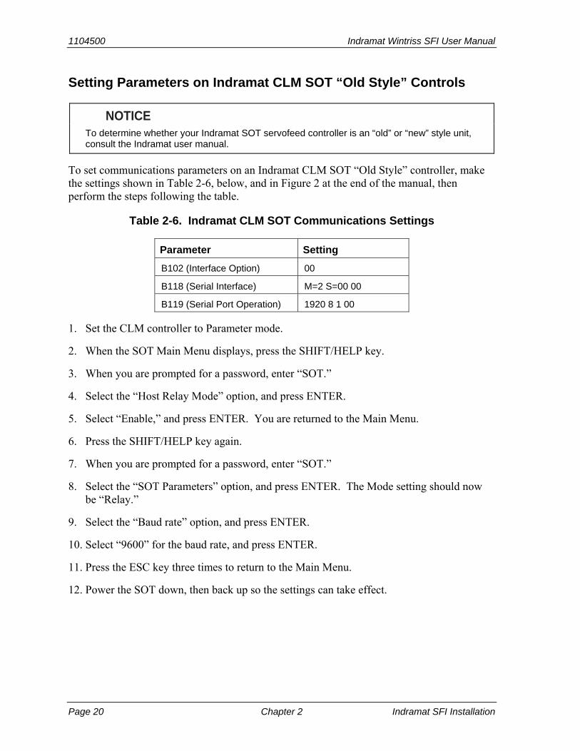
To set communications parameters on an Indramat CLM SOT “Old Style” controller, make the settings shown in Table 2-6, below, and in Figure 2 at the end of the manual, then perform the steps following the table.
Table 2-6. Indramat CLM SOT Communications Settings
Parameter Setting
B102 (Interface Option) 00
B118 (Serial Interface) M=2 S=00 00
B119 (Serial Port Operation) 1920 8 1 00
1. Set the CLM controller to Parameter mode.
2. When the SOT Main Menu displays, press the SHIFT/HELP key.
3. When you are prompted for a password, enter “SOT.”
4. Select the “Host Relay Mode” option, and press ENTER.
5. Select “Enable,” and press ENTER. You are returned to the Main Menu.
6. Press the SHIFT/HELP key again.
7. When you are prompted for a password, enter “SOT.”
8. Select the “SOT Parameters” option, and press ENTER. The Mode setting should now be “Relay.”
9. Select the “Baud rate” option, and press ENTER.
10. Select “9600” for the baud rate, and press ENTER.
11. Press the ESC key three times to return to the Main Menu.
12. Power the SOT down, then back up so the settings can take effect.

Indramat Wintriss SFI User Manual 1104500
Indramat SFI Installation Chapter 2 Page 21
Setting Parameters on Indramat CLM SOT “New Style” Controls
NOTICE To determine whether your Indramat SOT servofeed controller is an “old” or “new” style unit,
consult the Indramat user manual.
To set communications parameters on an Indramat CLM SOT “New Style” controller, make the settings shown in Table 2-6, above, and in Figure 2 at the end of the manual, then perform the following steps:
1. Set the CLM controller to Parameter mode.
2. When the SOT Main Menu displays, press the SHIFT/HELP key.
3. When you are prompted for a password, enter “SOT.”
4. Select the “Enable/Disable Relay Mode” option, then press ENTER to toggle to Enable mode.
5. Select the “SOT Parameters” option, and press ENTER.
6. Select “Port 2.”
7. Set the baud rate to “9600.”
8. Return to the Main Menu.
9. Power the SOT down, then back up so the settings can take effect.
Setting Parameters on Indramat DKS Controls
To set communications parameters on an Indramat DKS controller, first, install a DLC card, which enables the DKS to emulate a CLM Direct Connect controller, then make the settings shown in Table 2-7, below, and in Figure 3 at the end of the manual.
Table 2-7. Indramat DKS Communications Settings
Parameter Setting
B102 (Interface Option) 00
B118 (Serial Interface) M=1 S=00 00
B119 (Serial Port Operation) 9600 8 1 00

1104500 Indramat Wintriss SFI User Manual
Page 22 Chapter 2 Indramat SFI Installation
Setting Parameters on Indramat ECO BTV04 and BTV06 Controls
To set communications parameters on an Indramat ECO BTV04 or BTV06 controller, make the settings shown in Table 2-8 for a BTV04 terminal or Table 2-9 (next page ) for a BTV06 terminal. ECO communications settings are also shown in Figure 4 at the end of the manual.
NOTICE You can speed up communications between the Wintriss control and the DKC drive by putting
the BTV04 display into “Relay 2” mode (press F6 on the BTV04 terminal).
Table 2-8. Indramat ECO BTV04 Communications Settings
Port Parameter Setting
Address 0
Baud rate 9600
Protocol SIS Master
Parity None
Answer 4 ms delay
Timeout 400 ms
Retry 3
Group 0
BTV04 Port 1 (Connected to DKC)
Unit 0
Address 05 *
Baud rate 9600
Protocol ASCII
Parity None
Answer 0 ms delay
Timeout 500 ms
Retry 2
Group 0
BTV04 Port 2 (Connected to Wintriss Control)
Unit 0
B01 09600 1 05 DKC Port
B02 0 1 00 0 000
Wintriss Feed Control Initialization
Drive Address 5
* Same as DKC S3 setting and Feed Control Initialization of Wintriss Control

Indramat Wintriss SFI User Manual 1104500
Indramat SFI Installation Chapter 2 Page 23
Table 2-9. Indramat ECO BTV06 Communications Settings
Port Parameter Setting
Address 0
Baud rate 9600
Protocol SIS Master
Parity None
Hardware RS-232
Answer 5 ms delay
Timeout 400 ms
Retry 3
Group 0
BTV06 Port 1 (Connected to DKC)
Max Unit 0
Address 03 *
Baud rate 9600
Protocol ASCII + SIS
Parity None
Hardware RS-232
Answer 0 ms delay
Timeout 400 ms
Retry 0
Group 0
BTV06 Port 2 (Connected to Wintriss Control)
Max Unit 0
B01 09600 1 03 DKC Port
B02 0 1 00 0 000
Wintriss Feed Control Initialization
Drive Address 3
* Same as DKC S3 setting and Feed Control Initialization of Wintriss Control
Setting Parameters on Indramat RFX Controls with VCP08 Displays
There are no communications parameters you need to set on Indramat RFX controls, but you must turn on “Pass Through Mode VCP” at the display unit so that SmartPAC 2 can communicate with the Indramat control.

1104500 Indramat Wintriss SFI User Manual
Page 24 Chapter 2 Indramat SFI Installation

Indramat Wintriss SFI User Manual 1104500 Indramat SFI Initialization Mode Chapter 3 Page 25
Chapter 3 Indramat SFI Initialization Mode
This chapter shows you how to set several feed initialization parameters in Indramat SFI Initialization mode. Instructions are provided for both SmartPAC and Wintriss 1500 series controls.
NOTICE INDRAMAT SFI AND SMARTPAC 2
You can use Indramat SFI with SmartPAC 2 as well as with the original SmartPAC. Instructions provided in this manual that are specific to SmartPAC pertain to both SmartPAC 1 and SmartPAC 2 (refer to “SmartPAC 2 and Original SmartPAC,” page 4, for more information).
If you need additional help using Initialization mode in SmartPAC or 1500 series controls, refer to the applicable Wintriss user manual. For more information about your Indramat servofeed, refer to the appropriate Indramat servofeed manual.
Initializing Indramat SFI in SmartPAC
NOTICE Before setting Initialization parameters for your Indramat servofeed, you must have performed
the steps in "Setting Communications Parameters at Indramat," page 19. Communications parameters must be set before operating your Indramat SFI.
NOTICE READ YOUR INDRAMAT SERVOFEED MANUAL BEFORE MAKING ANY SETTINGS!
Make sure you have read the appropriate Indramat servofeed manual and understand how your servofeed works before making any Initialization settings changes.
To get into Initialization mode in SmartPAC, turn the Program/Run key to “PROGRAM” and then press both the “1” and “CLEAR” keys at the same time for one second. (See “Using the Keyboard” in Chapter 3 of the SmartPAC user manual.)

1104500 Indramat Wintriss SFI User Manual
Page 26 Chapter 3 Indramat SFI Initialization Mode
Initialization Menu
NOTICE Before changing modes (from Initialization to Program, for instance), make sure your screen
shows the first display in the sequence of displays for the mode you are in. If the first display does not appear on the screen, nothing will happen when you turn the Program /Run key. To return to the first display, press the RESET key repeatedly. Then turn the Program/Run key to switch to the new mode.
NOTICE SELECT = HIGHLIGHT + ENTER
When you are instructed in this manual to “select” a menu item, press the Up (▲) or Down (▼) cursor key on the Wintriss control keypad to highlight the item, then press the ENTER key.
The first display in Initialization mode (the order of items may vary depending on installed options) is shown in Figure 3-1. On this display, select “FEED CONTROL.”
MAIN INITIALIZATION MENU
USE CURSOR KEYS TOCHOOSE MENU ITEMS.PRESS THE ENTERKEY TO SELECT.SWITCH TO RUN WHENDONE.
RESOLVER ZEROPOSITION SENSORINSTALLED OPTIONSPRESS NAMEBRAKE MONITORSELECT CAM NAMESCUSTOM SENSOR NAMESSENSOR ENABLE MODESECURITY ACCESSAUTO ADVANCESET BRAKE MONITORFEED CONTROLFEED CONTROL
Figure 3-1. SmartPAC Main Initialization Menu with “FEED CONTROL” Selected
Initializing Feed Control Parameters
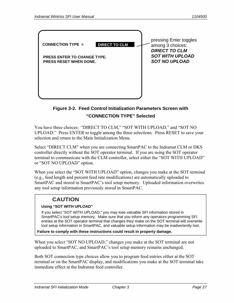
When you select “FEED CONTROL,” the Feed Control Initialization Parameters screen, shown in Figure 3-2 (next page), displays. You use this screen to select a connection type for your Indramat control.
NOTICE If you have an Indramat RFX feed with VCP08 display, a screen that allows you to set the units
type displays instead of the screen shown in Figure 3-2. To select a units type, scroll through the available options, using the ENTER key, then press RESET when the desired setting displays.
Indramat Wintriss SFI User Manual 1104500
Indramat SFI Initialization Mode Chapter 3 Page 27
PRESS ENTER TO CHANGE TYPE.PRESS RESET WHEN DONE.
DIRECT TO CLMCONNECTION TYPE =pressing Enter togglesamong 3 choices:DIRECT TO CLMSOT WITH UPLOADSOT NO UPLOAD
Figure 3-2. Feed Control Initialization Parameters Screen with
“CONNECTION TYPE” Selected
You have three choices: “DIRECT TO CLM,” “SOT WITH UPLOAD,” and “SOT NO UPLOAD.” Press ENTER to toggle among the three selections. Press RESET to save your selection and return to the Main Initialization Menu.
Select “DIRECT CLM” when you are connecting SmartPAC to the Indramat CLM or DKS controller directly without the SOT operator terminal. If you are using the SOT operator terminal to communicate with the CLM controller, select either the “SOT WITH UPLOAD” or “SOT NO UPLOAD” option.
When you select the “SOT WITH UPLOAD” option, changes you make at the SOT terminal (e.g., feed length and percent feed rate modifications) are automatically uploaded to SmartPAC and stored in SmartPAC’s tool setup memory. Uploaded information overwrites any tool setup information previously stored in SmartPAC.
CAUTION Using “SOT WITH UPLOAD”
If you select “SOT WITH UPLOAD,” you may lose valuable SFI information stored in SmartPAC’s tool setup memory. Make sure that you inform any operators programming SFI entries at the SOT operator terminal that changes they make on the SOT terminal will overwrite tool setup information in SmartPAC, and valuable setup information may be inadvertently lost.
Failure to comply with these instructions could result in property damage.
When you select “SOT NO UPLOAD,” changes you make at the SOT terminal are not uploaded to SmartPAC, and SmartPAC’s tool setup memory remains unchanged.
Both SOT connection type choices allow you to program feed entries either at the SOT terminal or on the SmartPAC display, and modifications you make at the SOT terminal take immediate effect at the Indramat feed controller.

1104500 Indramat Wintriss SFI User Manual
Page 28 Chapter 3 Indramat SFI Initialization Mode
Security Access
You use the “SECURITY ACCESS” item on the Main Initialization Menu to lock out “ADJUST FEED” so that unauthorized personnel cannot perform adjust feed settings in Run mode.
Locking Adjust Feed
To prevent unauthorized personnel from unlocking “ADJUST FEED,” you must remove the Program/Run key once SmartPAC is switched to Run mode. This will prevent unauthorized access into Initialization or Program modes, ensuring that feed settings cannot be unlocked or altered. The key has to be positioned at “PROGRAM” to get into these modes.
Select “SECURITY ACCESS” from the Main Initialization Menu to display the Security Access Menu, which is shown in Figure 3-3, below. Select the “PROGRAM AND RUN MODES” item to the right of the “ADJUST FEED” action. This is the default setting made at the factory and allows feed adjustments to be made in both Program and Run modes.
SECURITY ACCESS MENU
USE CURSOR KEYS TO MAKE CHOICES.PRESS THE ENTER KEY TO CHANGE THE MODES.PRESS THE RESET KEY WHEN DONE.
LOAD TOOL #SET CNTR PRESET:
CHANGE COUNT:RESET MODE:
ADJUST CAMS:ADJUST SENSORS:
DISABLE SENSORS:ADJUST FEED:
PROGRAM AND RUN MODESPROGRAM AND RUN MODESNO CHANGES ALLOWEDPROGRAM AND RUN MODESPROGRAM AND RUN MODESPROGRAM AND RUN MODESPROGRAM AND RUN MODESPROGRAM AND RUN MODESPROGRAM AND RUN MODES
Figure 3-3. SmartPAC Security Access Menu with Feed Adjustment Set for
both Program and Run Modes
To lock out the “ADJUST FEED” action so that it cannot be taken in Run mode, press the ENTER key with “PROGRAM AND RUN MODES” highlighted. The item to the right of “ADJUST FEED” changes to “PROGRAM MODE ONLY,” as shown in Figure 3-4 (next page), indicating that the feed controller can now be adjusted in Program mode only.

Indramat Wintriss SFI User Manual 1104500
Indramat SFI Initialization Mode Chapter 3 Page 29
SECURITY ACCESS MENU
USE CURSOR KEYS TO MAKE CHOICES.PRESS THE ENTER KEY TO CHANGE THE MODES.PRESS THE RESET KEY WHEN DONE.
LOAD TOOL #SET CNTR PRESET:
CHANGE COUNT:RESET MODE:
ADJUST CAMS:ADJUST SENSORS:
DISABLE SENSORS:ADJUST FEED:
PROGRAM AND RUN MODESPROGRAM AND RUN MODESNO CHANGES ALLOWEDPROGRAM AND RUN MODESPROGRAM AND RUN MODESPROGRAM AND RUN MODESPROGRAM AND RUN MODESPROGRAM AND RUN MODESPROGRAM MODE ONLY
Figure 3-4. SmartPAC Security Access Menu with Feed Adjustment Set for
Program Mode Only
If you do not want to make a change, press RESET to return to the Main Initialization menu.
Viewing Communications with the POSITION SENSOR Item
The “POSITION SENSOR” item on the Main Initialization Menu allows you to verify communications between SmartPAC and your Indramat feed controller. When you select “POSITION SENSOR,” the screen shown in Figure 3-5 displays.
POSITION SENSOR INPUT OPEN
PRESS THE CURSOR KEYS TO SELECT THE MODEYOU WANT TO CHANGE. PRESS THE ENTER KEY TOCHANGE IT. PRESS THE RESET KEY WHEN YOUARE DONE.
SORT TOOL TABLE F5
POSITION SENSOR MODE DISABLED
COUNTER SETUP MODE IS ALWAYS INCREMENTED
SHOW CHECKSUMS F6
VIEW COMMUNICATIONS F4
Figure 3-5. SmartPAC “Position Sensor” Display in Initialization Mode
Press function key F4 (“VIEW COMMUNICATIONS”) to display the Communication Data Viewer screen, shown in Figure 3-6 (next page).

1104500 Indramat Wintriss SFI User Manual
Page 30 Chapter 3 Indramat SFI Initialization Mode
PORT 1 (SFI)PORT 2 (MODULE)PORT 3 (SPECIAL)PORT 4 (PACNET)PORT 5 (WPC)
USE THE CURSOR KEYS TO CHOOSE THE PORTYOU WISH TO VIEW. PRESS THE ENTER KEY TOVIEW IT. PRESS THE RESET KEY WHEN DONE.
COMMUNICATION DATA VIEWER
PORT 1 (SFI)
NOTE: When viewing the port data you canperform a loop back test by jumpering the TXD andRXD lines together and then pressing the FI key.
Figure 3-6. SmartPAC Communication Data Viewer Screen
Select “PORT 1 (SFI)” on the Communications Data Viewer screen. The display shown in Figure 3-7 will appear.
TRANSMIT BUFFERdata that appearshere is beingtransmitted fromSmartPAC
data that appearshere is beingtransmitted from theservofeed controller
RECEIVE BUFFER
Figure 3-7. SmartPAC Communication Transmit/Receive Screen
If SmartPAC and the Indramat servofeed controller are communicating normally, you should expect to see some text (data) in both the “TRANSMIT BUFFER” and “RECEIVE BUFFER” portions of the screen. If you do not see any data (or only partial data), this means that SmartPAC and the servofeed controller are not communicating properly.
If there is a communications problem, you may decide to perform a loopback test. In a loopback test, you connect (or jumper) the TXD (Transmit) and RXD (Receive) lines (refer to Figure 6 at the end of this manual), and then press F1 to check communications. In effect, you are “receiving” the communications data that you are transmitting.

Indramat Wintriss SFI User Manual 1104500
Indramat SFI Initialization Mode Chapter 3 Page 31
This test is useful when verifying the accuracy of the transmit and receive hardware and wiring. If you need help performing the loopback test, contact Wintriss Tech Support.
Initializing Indramat SFI in a 1500 Series Control
NOTICE Before setting Initialization parameters for your Indramat servofeed, you must have performed
the steps in "Setting Communications Parameters at Indramat," page 19. Communications parameters must be set before operating your Indramat SFI.
NOTICE READ YOUR INDRAMAT SERVOFEED MANUAL BEFORE MAKING ANY SETTINGS!
Make sure you have read the appropriate Indramat servofeed manual and understand how your servofeed works before making any Initialization settings changes.
Initialization Menu
To get into Initialization mode in a 1500 control, turn the Program/Run key to “PROGRAM” and then press both the left and right “ANGLE-OFF” keys at the same time for one second. (See “Using the Keyboard” in Chapter 3 of the user manual for the applicable 1500 control.)
NOTICE Before changing modes (from Initialization to Program, for instance), make sure your screen
shows the first display in the sequence of displays for the mode you are in. If the first display does not appear on the screen, nothing will happen when you turn the Program /Run key. To return to the first display, press the RESET key repeatedly. Then turn the Program/Run key to switch to the new mode.
The first display in Initialization mode (the order of items may vary depending on installed options) is shown in Figure 3-8, below. On this display, select “FEED PARAMETERS.”
INITIALIZATIONMENU
USE CURSOR KEYS TO SELECT, ENTERTOSET, SWITCH TO RUN WHEN DONE
RESOLVER ZEROPOSITION SENSORSELECT CAM NAMESSECURITY ACCESSFEED PARAMETERS
Figure 3-8. 1500 Series Initialization Menu with “FEED PARAMETERS” Selected

1104500 Indramat Wintriss SFI User Manual
Page 32 Chapter 3 Indramat SFI Initialization Mode
Initializing Feed Control Parameters
When you select “FEED CONTROL,” the Feed Control Initialization Parameters screen, shown in Figure 3-9, below, displays. You use this screen to select a connection type for your Indramat control.
PRESS ENTER TO CHANGE TYPE.PRESS RESET WHEN DONE.
DIRECT TO CLMCONNECTION TYPE = pressing Enter togglesamong 3 choices:DIRECT TO CLMSOT WITH UPLOADSOT NO UPLOAD
Figure 3-9. 1500 Series Feed Control Initialization Parameters Screen with
“CONNECTION TYPE” Selected
You have three choices: “DIRECT TO CLM,” “SOT WITH UPLOAD,” and “SOT NO UPLOAD.” Press ENTER to toggle among the three selections. Press RESET to save your selection and return to the Initialization Menu.
Select “DIRECT CLM” when you are connecting the 1500 unit to the Indramat CLM or DKS controller directly without the SOT operator terminal. If you are using the SOT operator terminal to communicate with the CLM controller, select either the “SOT WITH UPLOAD” or “SOT NO UPLOAD” option.
When you select the “SOT WITH UPLOAD” option, changes you make at the SOT terminal (e.g., feed length and percent feed rate modifications) are automatically uploaded to the 1500 control and stored in the unit’s tool setup memory. Uploaded information overwrites any tool setup information previously stored at the 1500 control.
CAUTION Using “SOT WITH UPLOAD”
If you select “SOT WITH UPLOAD,” you may lose valuable SFI information stored in the 1500 control’s tool setup memory. Make sure that you inform any operators programming SFI entries at the SOT operator terminal that changes they make on the SOT terminal will overwrite tool setup information in the 1500 unit, and valuable setup information may be inadvertently lost.
Failure to comply with these instructions could result in property damage.
When you select “SOT NO UPLOAD,” changes you make at the SOT terminal are not uploaded to the 1500 control, and the unit’s tool setup memory remains unchanged.
Both SOT connection type choices allow you to program feed entries either at the SOT terminal or on the 1500 control’s LCD display, and modifications you make at the SOT terminal take immediate effect at the Indramat feed controller.
Indramat Wintriss SFI User Manual 1104500
Indramat SFI Initialization Mode Chapter 3 Page 33
Security Access
You use the “SECURITY ACCESS” item on the Initialization Menu to lock out “ADJUST FEED” so that unauthorized personnel cannot perform adjust feed settings in Run mode.
Locking Adjust Feed at ProCam 1500
To prevent unauthorized personnel from unlocking “ADJUST FEED” on a ProCam 1500 control, you must remove the Program/Run key once ProCam is switched to Run mode. This will prevent unauthorized access into the Initialization or Program modes, ensuring that feed settings cannot be unlocked or altered. The key has to be positioned at “PROGRAM” to get into these modes.
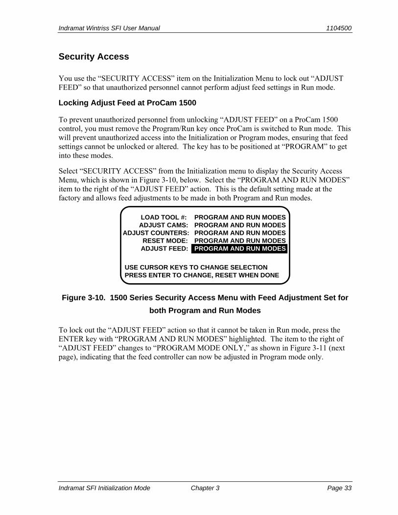
Select “SECURITY ACCESS” from the Initialization menu to display the Security Access Menu, which is shown in Figure 3-10, below. Select the “PROGRAM AND RUN MODES” item to the right of the “ADJUST FEED” action. This is the default setting made at the factory and allows feed adjustments to be made in both Program and Run modes.
USE CURSOR KEYS TO CHANGE SELECTIONPRESS ENTER TO CHANGE, RESET WHEN DONE
LOAD TOOL #: ADJUST CAMS:ADJUST COUNTERS: RESET MODE: ADJUST FEED:
PROGRAM AND RUN MODESPROGRAM AND RUN MODESPROGRAM AND RUN MODESPROGRAM AND RUN MODESPROGRAM AND RUN MODES
Figure 3-10. 1500 Series Security Access Menu with Feed Adjustment Set for
both Program and Run Modes
To lock out the “ADJUST FEED” action so that it cannot be taken in Run mode, press the ENTER key with “PROGRAM AND RUN MODES” highlighted. The item to the right of “ADJUST FEED” changes to “PROGRAM MODE ONLY,” as shown in Figure 3-11 (next page), indicating that the feed controller can now be adjusted in Program mode only.

1104500 Indramat Wintriss SFI User Manual
Page 34 Chapter 3 Indramat SFI Initialization Mode
USE CURSOR KEYS TO CHANGE SELECTIONPRESS ENTER TO CHANGE, RESET WHEN DONE
LOAD TOOL #: ADJUST CAMS:ADJUST COUNTERS: RESET MODE: ADJUST FEED:
PROGRAM AND RUN MODESPROGRAM AND RUN MODESPROGRAM AND RUN MODESPROGRAM AND RUN MODESPROGRAM MODE ONLY
Figure 3-11. 1500 Series Security Access Menu with Feed Adjustment Set for
Program Mode Only
If you do not want to make a change, press RESET to return to the Initialization menu.
Locking Adjust Feed at DiPro 1500
NOTICE DIPRO 1500 AUTO ADVANCE AND SECURITY
In DiPro 1500, “Auto Advance” and “Adjust Feed“ security are not main Initialization choices. (SFI was not originally offered with DiPro 1500.) Instead, feed-specific selections are grouped under Feed Initialization. To change default “Auto Advance” and “Adjust Feed” settings, you must select the “Feed Parameters 2” item on the DiPro 1500 Initialization Menu (see Figure 3-12, below). Only DiPro 1500’s Channel 1 can be an auto advance channel with SFI.
To prevent unauthorized personnel from unlocking “ADJUST FEED,” you must remove the Program/Run key once DiPro is switched to Run mode. This will prevent unauthorized access into Initialization or Program modes, ensuring that feed settings cannot be unlocked or altered. The key has to be positioned at “PROGRAM” to get into these modes.
INITIALIZATION RESOLVER ZEROMENU POSITION SENSOR
PACNETSELECT CAM NAMESSECURITY ACCESSFEED PARAMETERS 1FEED PARAMETERS 2
USE CURSOR KEYS TO SELECT, ENTER TO SETSWITCH TO RUN WHEN DONE.
Figure 3-12. DiPro 1500 Initialization Menu with “FEED PARAMETERS 2”
Selected

Indramat Wintriss SFI User Manual 1104500
Indramat SFI Initialization Mode Chapter 3 Page 35
Select “FEED PARAMETERS 2” from the DiPro 1500 Initialization Menu (see Figure 3-12, above) to display the Feed Parameters 2 Initialization screen, which is shown in Figure 3-13, below. Select the “PROGRAM AND RUN MODES” item to the right of the “ADJUST FEED” action. This is the default setting made at the factory and allows feed adjustments to be made in both Program and Run modes.
USE CURSOR KEYS TO MAKE SELECTIONPRESS ENTER TO CHANGE. RESET WHEN DONE
ADJUST FEED:ADV. CONST. CH 1: SLOW RPM:
PROGRAM AND RUN MODES0 DEG / 100 SPM100
Figure 3-13. DiPro 1500 Feed Parameters 2 Initialization Screen with Feed
Adjustment Set for both Program and Run Modes
To lock out the “ADJUST FEED” action so that it cannot be taken in Run mode, press the ENTER key with “PROGRAM AND RUN MODES” highlighted. The item to the right of “ADJUST FEED” changes to “PROGRAM MODE ONLY,” indicating that the feed controller can now be adjusted in Program mode only.
If you do not want to make a change, press RESET to return to the Initialization menu.
Auto Advance and Slow RPM in DiPro 1500
Determining the Advance Constant for Channel 1 Automatic Speed Compensation
You use the “ADV. CONST. CH 1” selection on the Feed Parameters 2 Initialization screen to set an auto advance constant for the cam channel 1 auto advance function. Cam functions that may use auto advance are feed advance and pilot release. Auto advance works best on presses that have a speed range of several hundred to over a thousand strokes per minute.
The auto advance constant is equal to the number of degrees of advance per 100 RPM increase in press speed.
A.C. = # °/100 RPM
To calculate the auto advance constant for pilot release, follow these steps:
1. Determine the fastest press speed (RPMa) and the optimum angle at which the pilot release cam should turn on at this speed (Aa).
2. Determine the slowest press speed (RPMb) and the optimum angle at which the pilot release cam should turn on at this speed (Ab).

1104500 Indramat Wintriss SFI User Manual
Page 36 Chapter 3 Indramat SFI Initialization Mode
3. Subtract the two angle values. We will call this result “Ac.”
Aa - Ab = Ac
4. Subtract the two press speeds. We will call this result “RPMc.”
RPMa - RPMb = RPMc
5. Divide Ac (the difference between the angles) by RPMc (the difference between the press speeds), and multiply that value by 100. The result is the number of degrees per 100 RPM.
Ac x 100 = # ° / 100 RPM RPMc
Example: Calculating the Auto Advance Setting
Your fastest speed is 100 RPM and the pilot release angle at that speed is 75°.
Your slowest speed is 50 RPM and the pilot release angle at that speed is 100°.
Subtract 50 RPM from 100 RPM. 100 - 50 = 50
Subtract 75° from 100°. 100 - 75 = 25
Divide the difference in angles by the difference in RPM, and multiply the quotient by 100. The result is your advance constant – in this example, 50°.
25 x 100 = 50.00 ==> 50° / 100 RPM 50
NOTICE MORE ON ADVANCE CONSTANT SETTINGS
You can make only one auto advance constant setting. This setting will automatically be applied to channel 1, but it will not be displayed as an “auto” setting in Program or Run modes.
If you do not wish to use the Auto Advance feature, leave the “ADV. CONST. CH 1” setting at its default value of zero (0).
Auto Advance does not function if channel 1 has been programmed as a “timed output.” See Chapter 5 in the DiPro 1500 user manual for more information about making cam channel settings.

Indramat Wintriss SFI User Manual 1104500
Indramat SFI Initialization Mode Chapter 3 Page 37
Setting the Auto Advance Constant
To set the Auto Advance Constant, move the highlight bar to the “ADV. CONST. CH 1” item on the Feed Parameters 2 Initialization screen (see Figure 3-13, above), and press ENTER. The prompt displayed at the bottom of the screen will change, as shown in Figure 3-14, below.
USE CURSOR KEYS TO CHANGE ADVANCE CONST. PRESS RESET WHEN DONE
ADJUST FEED:ADV. CONST. CH 1: SLOW RPM:
PROGRAM AND RUN MODES0 DEG / 100 SPM0
Figure 3-14. DiPro 1500 Feed Parameters 2 Initialization Screen with “ADV.
CONST. CH 1” Selected
As directed in the prompt, use the Up (▲) or Down (▼) cursor key on your DiPro 1500 keypad to increment or decrement the “ADV. CONST. CH. 1” value. The range for this value is 0-500.
Setting Slow RPM
In calculating an auto advance constant, you must determine the slowest speed at which your press will operate. This value is entered in the “SLOW RPM” field on the Feed Parameters 2 Initialization screen. DiPro uses the “SLOW RPM” value as a starting point in the auto advance process. If an incorrect number is entered in the “SLOW RPM” field, DiPro will not begin to auto advance at the right time. In the example above, you would set slow RPM to 50.
To set Slow RPM, move the highlight bar to the “SLOW RPM” item on the Feed Parameters 2 Initialization screen, and press ENTER. Use the Up (▲) or Down (▼) cursor key on the DiPro 1500 keypad to increment or decrement the “SLOW RPM” value. The value increases or decreases 5 units for each depression of the Up (▲) or Down (▼) cursor key. The range for Slow RPM is 0-2000 RPM.

1104500 Indramat Wintriss SFI User Manual
Page 38 Chapter 3 Indramat SFI Initialization Mode
Indramat Wintriss SFI User Manual 1104500 Indramat SFI Program Mode Chapter 4 Page 39
Chapter 4 Indramat SFI Program Mode
This chapter shows you how to use Indramat SFI in Program mode. You will learn how to perform the following actions:
• Set feed parameters • Use the Feed Advisor • Load feed settings
NOTICE INDRAMAT SFI AND SMARTPAC 2
You can use Indramat SFI with SmartPAC 2 as well as with the original SmartPAC. Instructions provided in this manual that are specific to SmartPAC pertain to both SmartPAC 1 and SmartPAC 2 (refer to “SmartPAC 2 and Original SmartPAC,” page 4, for more information).
If you need additional help with your Wintriss product, refer to the applicable Wintriss user manual. Refer to the appropriate Indramat servofeed manual for more information about your Indramat servofeed.
Using Indramat SFI Program Mode in SmartPAC
NOTICE READ YOUR INDRAMAT SERVOFEED MANUAL BEFORE MAKING ANY SETTINGS!
Make sure you have read the appropriate Indramat servofeed manual and understand how your servofeed works before making any settings.
About Tool Number
A tool number consists of all the programmed settings (including servofeed settings) that you make for one job. You can save servofeed information for up to 200 tools and then recall these settings for each job whenever you need to.
Program Menu
You enter Program mode by turning the Program/Run key to “RUN” and then back to “PROGRAM.” Next, select a tool number to modify, and then select “MODIFY THE TOOL NUMBER INFORMATION.” If you are not sure how to program a tool, refer to Chapter 5 in the SmartPAC user manual.
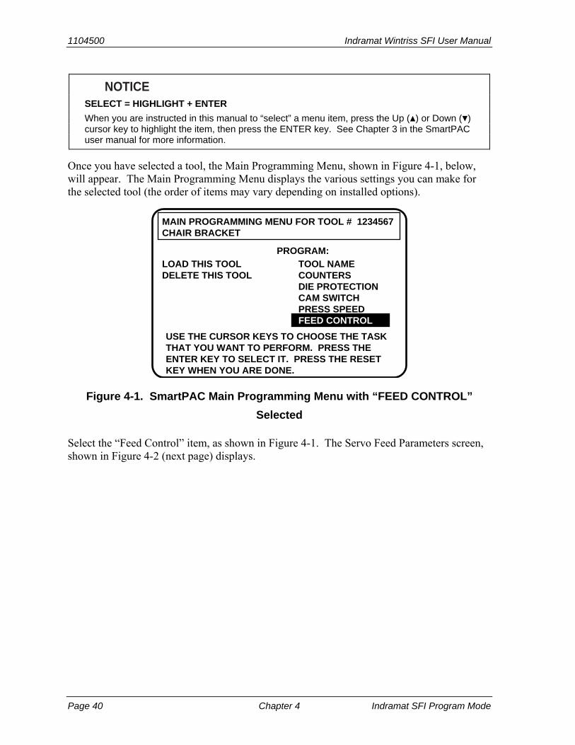
1104500 Indramat Wintriss SFI User Manual
Page 40 Chapter 4 Indramat SFI Program Mode
NOTICE SELECT = HIGHLIGHT + ENTER
When you are instructed in this manual to “select” a menu item, press the Up (▲) or Down (▼) cursor key to highlight the item, then press the ENTER key. See Chapter 3 in the SmartPAC user manual for more information.
Once you have selected a tool, the Main Programming Menu, shown in Figure 4-1, below, will appear. The Main Programming Menu displays the various settings you can make for the selected tool (the order of items may vary depending on installed options).
USE THE CURSOR KEYS TO CHOOSE THE TASKTHAT YOU WANT TO PERFORM. PRESS THEENTER KEY TO SELECT IT. PRESS THE RESETKEY WHEN YOU ARE DONE.
TOOL NAMECOUNTERSDIE PROTECTIONCAM SWITCHPRESS SPEEDFEED CONTROLFEED CONTROL
LOAD THIS TOOLDELETE THIS TOOL
PROGRAM:
MAIN PROGRAMMING MENU FOR TOOL # 1234567CHAIR BRACKET
Figure 4-1. SmartPAC Main Programming Menu with “FEED CONTROL”
Selected
Select the “Feed Control” item, as shown in Figure 4-1. The Servo Feed Parameters screen, shown in Figure 4-2 (next page) displays.

Indramat Wintriss SFI User Manual 1104500
Indramat SFI Program Mode Chapter 4 Page 41
SERVO FEED PARAMETERS
FEED LENGTH 2.252 INCHES% FEED RATE 10 %FEED ADVISOR
USE THE CURSOR KEYS TO SELECT THE VALUEYOU WANT TO CHANGE. PRESS THE ENTER KEYTO CHANGE IT. PRESS RESET WHEN DONE.
2.252
USE THE KEYPAD TO ENTER NUMBERS.USE THE UP/DOWN CURSOR KEYS TOINCREASE/DECREASE. PRESS ENTERWHEN DONE. PRESS RESET TO CANCEL.
Press ENTER here todisplay the Servo-FeedAdvisor screen.
Select either of theseitems to display the ChangeParameters window soyou can change values.
Figure 4-2. SmartPAC Servo Feed Parameters Screen with Change
Parameters Window
Feed Settings
When you select “FEED LENGTH,” a Change Parameters window displays, allowing you to set or change the Feed Length value. Use the number keys to input a desired feed length, or the Up (▲) or Down (▼) cursor key to increment or decrement the displayed value.
When you are done, press ENTER. SmartPAC will accept the number and move on to the next display. SmartPAC accepts numbers up to seven digits in length.
NOTICE If you need help using the number or cursor keys, refer to Chapter 3 in your SmartPAC user
manual.
The “% FEED RATE” item allows you to change the current Percent Feed Rate value. However, if your Indramat servofeed supports Feed Advisor and you plan to use this feature, you do not need to set a percent feed rate. See the instructions in the next section to access the Feed Advisor.
If you wish to leave the Servo Feed Parameters screen without making any changes, press RESET.
Feed Advisor
Feed Advisor is a convenience which saves you the time of calculating the percent feed rate yourself. When using Feed Advisor, you need to enter feed length, feed arc (number of crankshaft degrees available to fully feed the material), and press speed. When determining the percent feed rate, take into consideration the feed initiate angle, which may be programmed as one of the cam timings in SmartPAC.
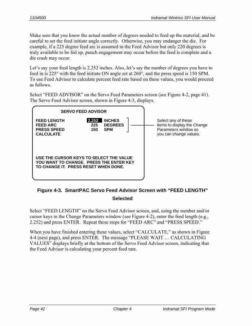
1104500 Indramat Wintriss SFI User Manual
Page 42 Chapter 4 Indramat SFI Program Mode
Make sure that you know the actual number of degrees needed to feed up the material, and be careful to set the feed initiate angle correctly. Otherwise, you may endanger the die. For example, if a 225 degree feed arc is assumed in the Feed Advisor but only 220 degrees is truly available to be fed up, punch engagement may occur before the feed is complete and a die crash may occur.
Let’s say your feed length is 2.252 inches. Also, let’s say the number of degrees you have to feed in is 225° with the feed initiate ON angle set at 260°, and the press speed is 150 SPM. To use Feed Advisor to calculate percent feed rate based on these values, you would proceed as follows.
Select “FEED ADVISOR” on the Servo Feed Parameters screen (see Figure 4-2, page 41). The Servo Feed Advisor screen, shown in Figure 4-3, displays.
SERVO FEED ADVISOR
FEED LENGTH 2.252 INCHESFEED ARC 225 DEGREESPRESS SPEED 150 SPMCALCULATE
USE THE CURSOR KEYS TO SELECT THE VALUEYOU WANT TO CHANGE. PRESS THE ENTER KEYTO CHANGE IT. PRESS RESET WHEN DONE.
Select any of theseitems to display the ChangeParameters window soyou can change values.
Figure 4-3. SmartPAC Servo Feed Advisor Screen with “FEED LENGTH”
Selected
Select “FEED LENGTH” on the Servo Feed Advisor screen, and, using the number and/or cursor keys in the Change Parameters window (see Figure 4-2), enter the feed length (e.g., 2.252) and press ENTER. Repeat these steps for “FEED ARC” and “PRESS SPEED.”
When you have finished entering these values, select “CALCULATE,” as shown in Figure 4-4 (next page), and press ENTER. The message “PLEASE WAIT … CALCULATING VALUES” displays briefly at the bottom of the Servo Feed Advisor screen, indicating that the Feed Advisor is calculating your percent feed rate.

Indramat Wintriss SFI User Manual 1104500
Indramat SFI Program Mode Chapter 4 Page 43
SERVO FEED ADVISOR
FEED LENGTH 2.252 INCHESFEED ARC 225 DEGREESPRESS SPEED 150 SPMCALCULATE
USE THE CURSOR KEYS TO SELECT THE VALUEYOU WANT TO CHANGE. PRESS THE ENTER KEYTO CHANGE IT. PRESS RESET WHEN DONE.
Press ENTER with“CALCULATE” selectedto have SmartPACcalculate the percent feedrate automatically.
Figure 4-4. SmartPAC Servo Feed Advisor Screen with “CALCULATE”
Selected
Before displaying its calculations, Feed Advisor displays messages indicating whether the feed length and feed arc you entered are valid for the specified press speed. For instance, if Feed Advisor determines that the feed has plenty of time to complete based on the values entered, you will see this message at the bottom of the Servo Feed Advisor screen:
THE MATERIAL WILL BE FED UP WELL BEFORE THE FEED ARC IS COMPLETED.
This means that the feed will end well before the end of the feed arc you have entered even when it is operating at the lowest speed specified in Initialization.
The following message
THE MATERIAL WILL BE FED UP JUST AS THE FEED ARC IS COMPLETED.
indicates that the feed will end just as the feed arc is completed. This is the optimum condition because feed never has to reach the maximum speed specified in Initialization.
If you entered values that will not allow the feed to complete before the end of the feed arc, you will see this message:
THE MATERIAL CANNOT BE FED UP IN TIME. MORE TIME MUST BE ALLOWED.

1104500 Indramat Wintriss SFI User Manual
Page 44 Chapter 4 Indramat SFI Program Mode
In this case, you will have to revise the values you entered on the Servo Feed Advisor screen. You may need to lengthen the feed arc, assuming that a longer feed arc will not affect other actions such as part transfer or part cut off. If you choose to lengthen the arc, make sure that you reprogram the cam angle to initiate the feed earlier. If you cannot lengthen the feed arc, your other option is to decrease press speed. When you have revised your figures, calculate the percent feed rate again.
When the message displayed by Feed Advisor indicates that the values you entered are acceptable, press the RESET key. You are returned to the Servo Feed Parameters screen (see Figure 4-2, page 41), on which Feed Advisor has refreshed the value in the “% FEED RATE” field based on the values you entered on the Servo Feed Advisor screen.
NOTICE USING FEED ADVISOR
You can use Feed Advisor any time that you want SmartPAC to calculate the percent feed rate for you. If you want to manually enter your own percent feed rate, select that item on the Servo Feed Parameters screen (see Figure 4-2, page 41).
Remember to program the “Feed Initiate angle” as the “on” angle of the “Feed Advance” cam in SmartPAC ProCamPAC!
Loading by Tool Number
You can automatically load feed settings by tool number. To load a tool number, press RESET twice, the first time to exit from the Servo Feed Parameters screen, the second to display the Load Tool Number screen. Press ENTER to load (or RESET to back out). You will get a message like this, confirming that you have successfully loaded the tool:
PLEASE WAIT … LOADING TOOL 1
Loading by tool numbers is covered in Chapter 5 (Program mode) and Chapter 6 (Run mode) of the SmartPAC user manual.
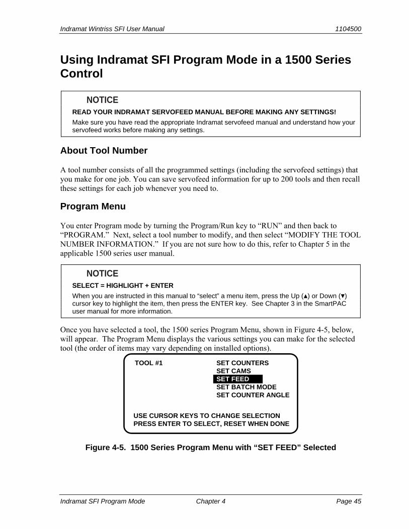
Indramat Wintriss SFI User Manual 1104500
Indramat SFI Program Mode Chapter 4 Page 45
Using Indramat SFI Program Mode in a 1500 Series Control
NOTICE READ YOUR INDRAMAT SERVOFEED MANUAL BEFORE MAKING ANY SETTINGS!
Make sure you have read the appropriate Indramat servofeed manual and understand how your servofeed works before making any settings.
About Tool Number
A tool number consists of all the programmed settings (including the servofeed settings) that you make for one job. You can save servofeed information for up to 200 tools and then recall these settings for each job whenever you need to.
Program Menu
You enter Program mode by turning the Program/Run key to “RUN” and then back to “PROGRAM.” Next, select a tool number to modify, and then select “MODIFY THE TOOL NUMBER INFORMATION.” If you are not sure how to do this, refer to Chapter 5 in the applicable 1500 series user manual.
NOTICE SELECT = HIGHLIGHT + ENTER
When you are instructed in this manual to “select” a menu item, press the Up (▲) or Down (▼) cursor key to highlight the item, then press the ENTER key. See Chapter 3 in the SmartPAC user manual for more information.
Once you have selected a tool, the 1500 series Program Menu, shown in Figure 4-5, below, will appear. The Program Menu displays the various settings you can make for the selected tool (the order of items may vary depending on installed options).
TOOL #1 SET COUNTERSSET CAMSSET FEEDSET BATCH MODESET COUNTER ANGLE
USE CURSOR KEYS TO CHANGE SELECTIONPRESS ENTER TO SELECT, RESET WHEN DONE
Figure 4-5. 1500 Series Program Menu with “SET FEED” Selected

1104500 Indramat Wintriss SFI User Manual
Page 46 Chapter 4 Indramat SFI Program Mode
Select the “SET FEED” item, as shown in Figure 4-5. The Servo Feed Parameters screen, shown in Figure 4-6, displays.
SERVO FEED PARAMETERS
FEED LENGTH 2.252 INCHES% FEED RATE 10 %FEED ADVISOR
USE THE CURSOR KEYS TO SELECT THE VALUEYOU WANT TO CHANGE. PRESS THE ENTER KEYTO CHANGE IT. PRESS RESET WHEN DONE.
Select either of theseitems, then use the cursorkeys to change the values.
Press ENTER here todisplay the Servo-FeedAdvisor screen.
Figure 4-6. 1500 Series Servo Feed Parameters Screen with “FEED LENGTH”
Selected
Feed Settings
When you select “FEED LENGTH” on the Servo Feed Parameters screen, the Feed Length screen, shown in Figure 4-7, displays, allowing you to set the Feed Length value.
0002.252
USE LEFT / RIGHT CURSORS TO SELECT DIGITSUSE UP / DOWN CURSORS TO CHANGE VALUESPRESS ENTER WHEN DONE, RESET TO CANCEL
FEED LENGTH
Figure 4-7. 1500 Series Feed Length Screen
Following the directions in the prompt at the bottom of the screen, use the Left (◄) or Right (►) cursor key to select the digit you want to change (the wedge-shaped pointer moves to the selected digit) and the Up (▲) or Down (▼) cursor key to increment or decrement that digit. When you are satisfied with the value, press the ENTER key.
NOTICE If you need help using the cursor keys, refer to Chapter 3 in the applicable 1500 series user
manual.

Indramat Wintriss SFI User Manual 1104500
Indramat SFI Program Mode Chapter 4 Page 47
The “% FEED RATE” item on the Servo Feed Parameters screen allows you to change the current Percent Feed Rate value. However, if your Indramat servofeed supports Feed Advisor and you plan to use this feature, you do not need to set a percent feed rate. See the instructions in the next section to access the Feed Advisor.
If you wish to leave this screen without making a change, press RESET.
Feed Advisor
Feed Advisor is a convenience which saves you the time of calculating the percent feed rate yourself. When using Feed Advisor, you need to enter feed length, feed arc (number of crankshaft degrees available to fully feed the material), and press speed. When determining the percent feed rate, take into consideration the feed initiate angle, which may be programmed as one of the cam timings in SmartPAC.
Make sure that you know the actual number of degrees needed to feed up the material, and be careful to set the feed initiate angle correctly. Otherwise, you may endanger the die. For example, if a 225 degree feed arc is assumed in the Feed Advisor but only 220 degrees is truly available to be fed up, punch engagement may occur before the feed is complete and a die crash may occur.
Let’s say your feed length is 2.252 inches. Also, let’s say the number of degrees you have to feed in is 225° with the feed initiate ON angle set at 260°, and the press speed is 150 SPM. To use Feed Advisor to calculate percent feed rate based on these values, you would proceed as follows.
Select “FEED ADVISOR” on the Servo Feed Parameters screen (see Figure 4-6, page 46). The Servo Feed Advisor screen, shown in Figure 4-8, below, displays.
SERVO FEED ADVISORFEED LENGTH 2.252 INCHESFEED ARC 225 DEGREESPRESS SPEED 150 SPMCALCULATE
USE THE CURSOR KEYS TO SELECT THE VALUEYOU WANT TO CHANGE. PRESS THE ENTER KEYTO CHANGE IT. PRESS RESET WHEN DONE.
Select any of theseitems, then use the cursorkeys to change its value.
Press ENTER here todisplay the Servo-FeedAdvisor screen.
Figure 4-8. 1500 Series Servo Feed Advisor Screen with “FEED LENGTH”
Selected
Select “FEED LENGTH” on the Servo Feed Advisor screen, and, following the directions in the prompt that displays at the bottom of the screen, use the number and/or cursor keys to enter the feed length (e.g., 2.252). Press ENTER. Repeat these steps for “FEED ARC” and “PRESS SPEED.”

1104500 Indramat Wintriss SFI User Manual
Page 48 Chapter 4 Indramat SFI Program Mode
When you have finished entering these values, select “CALCULATE,” as shown in Figure 4-9.
SERVO FEED ADVISORFEED LENGTH 2.252 INCHESFEED ARC 225 DEGREESPRESS SPEED 150 SPMCALCULATE
USE THE CURSOR KEYS TO SELECT THE VALUEYOU WANT TO CHANGE. PRESS THE ENTER KEYTO CHANGE IT. PRESS RESET WHEN DONE.
Press ENTER with“CALCULATE” selectedto have the 1500 controlcalculate the percent feedrate automatically.
Figure 4-9. 1500 Series Servo Feed Advisor Screen with “CALCULATE”
Selected
The following message displays briefly at the bottom of the screen
PLEASE WAIT … CALCULATING PARAMETERS
indicating that the Feed Advisor is calculating your percent feed rate.
Before displaying its calculations, Feed Advisor displays messages indicating whether the feed length and feed arc you entered are valid for the specified press speed. For instance, if Feed Advisor determines that the feed has plenty of time to complete based on the values entered, you will see this message at the bottom of the Servo Feed Advisor screen:
THE MATERIAL WILL BE FED UP WELL BEFORE THE FEED ARC IS COMPLETED.
This means that the feed will end well before the end of the feed arc you have entered.
The following message
THE MATERIAL WILL BE FED UP JUST AS THE FEED ARC IS COMPLETED.
indicates that the feed will end just as the feed arc is completed. This is the optimum condition.
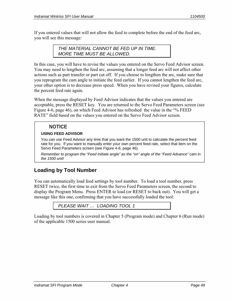
Indramat Wintriss SFI User Manual 1104500
Indramat SFI Program Mode Chapter 4 Page 49
If you entered values that will not allow the feed to complete before the end of the feed arc, you will see this message:
THE MATERIAL CANNOT BE FED UP IN TIME. MORE TIME MUST BE ALLOWED.
In this case, you will have to revise the values you entered on the Servo Feed Advisor screen. You may need to lengthen the feed arc, assuming that a longer feed arc will not affect other actions such as part transfer or part cut off. If you choose to lengthen the arc, make sure that you reprogram the cam angle to initiate the feed earlier. If you cannot lengthen the feed arc, your other option is to decrease press speed. When you have revised your figures, calculate the percent feed rate again.
When the message displayed by Feed Advisor indicates that the values you entered are acceptable, press the RESET key. You are returned to the Servo Feed Parameters screen (see Figure 4-6, page 46), on which Feed Advisor has refreshed the value in the “% FEED RATE” field based on the values you entered on the Servo Feed Advisor screen.
NOTICE USING FEED ADVISOR
You can use Feed Advisor any time that you want the 1500 unit to calculate the percent feed rate for you. If you want to manually enter your own percent feed rate, select that item on the Servo Feed Parameters screen (see Figure 4-6, page 46).
Remember to program the “Feed Initiate angle” as the “on” angle of the “Feed Advance” cam in the 1500 unit!
Loading by Tool Number
You can automatically load feed settings by tool number. To load a tool number, press RESET twice, the first time to exit from the Servo Feed Parameters screen, the second to display the Program Menu. Press ENTER to load (or RESET to back out). You will get a message like this one, confirming that you have successfully loaded the tool:
PLEASE WAIT … LOADING TOOL 1
Loading by tool numbers is covered in Chapter 5 (Program mode) and Chapter 6 (Run mode) of the applicable 1500 series user manual.

1104500 Indramat Wintriss SFI User Manual
Page 50 Chapter 4 Indramat SFI Program Mode
Indramat Wintriss SFI User Manual 1104500 Indramat SFI Run Mode Chapter 5 Page 51
Chapter 5 Indramat SFI Run Mode
This chapter shows you how to use Indramat SFI in Run mode. You will learn how to adjust feed parameters while operating the press.
NOTICE INDRAMAT SFI AND SMARTPAC 2
You can use Indramat SFI with SmartPAC 2 as well as with the original SmartPAC. Instructions provided in this manual that are specific to SmartPAC pertain to both SmartPAC 1 and SmartPAC 2 (refer to “SmartPAC 2 and Original SmartPAC,” page 4, for more information).
If you need additional help with your Wintriss product, refer to the applicable Wintriss user manual. Refer to the appropriate Indramat servofeed manual for more information about your Indramat servofeed.
NOTICE READ YOUR INDRAMAT SERVOFEED MANUAL BEFORE MAKING ANY SETTINGS!
Make sure you have read the appropriate Indramat servofeed manual and understand how your servofeed works before making any settings.
Using Indramat SFI Run Mode in SmartPAC
About Tool Numbers
A tool number consists of all of the settings (including the servofeed settings) that you make for one job. You can save servofeed information for up to 200 tools and then recall the settings for each job whenever you need to.
NOTICE SELECT = HIGHLIGHT + ENTER
When you are instructed in this manual to “select” a menu item, press the Up (▲) or Down (▼) cursor key to highlight the item, then press the ENTER key. See Chapter 3 in the SmartPAC user manual for more information.

1104500 Indramat Wintriss SFI User Manual
Page 52 Chapter 5 Indramat SFI Run Mode
Run Menu
While you are running the press, SmartPAC will operate the Indramat servofeed based upon the settings you have made in Program mode. In some cases, you can make minor adjustments to the currently loaded tool number.
To use Run mode, turn the Program/Run key to “RUN.” The Run Menu, shown in Figure 5-1, will display (the order of items may vary depending on installed options).
USE CURSOR KEYS TOMAKE SELECTIONS.PRESS ENTER TO ACCESSSELECTION.
DISABLE SENSORSCOUNTERSBRAKE MONITORDIE PROTECTIONCAM SWITCHPRESS SPEEDFEED CONTROLLOAD NEW TOOL
TOOL NUMBER 1234567CHAIR BRACKETCRITICAL ANGLE 0
SENSOR 1PART EJECTIONGREEN ESTOP
FEED CONTROL
Figure 5-1. SmartPAC Run Menu with “FEED CONTROL” Selected
To adjust feed settings, select “FEED CONTROL.” The Feed Control screen, shown in Figure 5-2, below, displays.
FEED LENGTH% FEED RATE
INCHES%
USE THE CURSOR KEYS TO SELECT. PRESS ENTERTO CHANGE. PRESS RESET KEY WHEN DONE.
TOOL NUMBER 1234567 PART CNTR 0CHAIR BRACKETSENSORS ENABLED
2.25210
2.252
Figure 5-2. SmartPAC Feed Control Screen with “FEED LENGTH” Selected

Indramat Wintriss SFI User Manual 1104500
Indramat SFI Run Mode Ch 5 Page 53
This screen allows you to make minor adjustments to Feed Length and Percent Feed Rate. To do so, you select an item, then use the Up (▲) or Down (▼) cursor key to increment or decrement the value for that item. Note that the Feed Length value changes by .001 inch (1/1000) or less each time you press the Up (▲) or Down (▼) key.
Changes you make to settings on this screen are sent directly to the servofeed and saved immediately to the currently loaded tool. Be sure to make a note of feed setup changes on your feed setup sheet for future reference.
When you are done, press the RESET key to exit from this display.
Using Indramat SFI Run Mode in a 1500 Series Control
About Tool Numbers
A tool number consists of all of the settings (including the servofeed settings) that you make for one job. You can save servofeed information for up to 200 tools and then recall the settings for each job whenever you need to.
Run Menu
While you are running the press, the 1500 control will operate the servofeed based on the settings you made in Program mode. In some cases, you can make minor adjustments to the currently loaded tool number.
To use Run mode, turn the Program/Run key to “RUN.” The Run Menu, shown in Figure 5-3, displays.
TOOL NUMBER 1 COUNTERSADJUST CAMSADJUST FEEDSTOP TIMESHOW TIMINGLOAD TOOL #USE CURSOR KEYS TO
MAKE SELECTIONS.PRESS ENTER TO ACCESSSELECTION.
Figure 5-3. 1500 Series Run Menu with “ADJUST FEED” Selected
To adjust feed settings, select “ADJUST FEED.” The Adjust Feed screen, shown in Figure 5-4 (next page), displays.

1104500 Indramat Wintriss SFI User Manual
Page 54 Chapter 5 Indramat SFI Run Mode
FEED LENGTH% FEED RATE
INCHES%
USE THE CURSOR KEYS TO SELECT. PRESS ENTERTO CHANGE. PRESS RESET KEY WHEN DONE.
2.25210
2.252
Figure 5-4. 1500 Series Adjust Feed Screen with “FEED LENGTH” Selected
This screen allows you to make minor adjustments to Feed Length and Percent Feed Rate. To do so, you select an item, then use the Up (▲) or Down (▼) cursor key to increment or decrement the value for that item. Note that the Feed Length value changes by .001 inch (1/1000) or less each time you press the Up (▲) or Down (▼) key.
Changes you make to settings on this screen are sent directly to the servofeed and saved immediately to the currently loaded tool. Be sure to make a note of feed setup changes on your feed setup sheet for future reference.
When you are done, press the RESET key to exit from the Adjust Feed screen.

Indramat Wintriss SFI User Manual 1104500 Indramat SFI Troubleshooting Chapter 6 Page 55
Chapter 6 Indramat SFI Troubleshooting
This chapter documents troubleshooting messages that are generated because of problems with the interface between the Indramat servofeed and the Wintriss control and shows you how to respond to them. It does not cover other Wintriss- or Indramat-generated fault messages. Consult the appropriate Wintriss control or Indramat servofeed user manual for these faults.
This chapter covers the communications fault message on SmartPAC and 1500 series controls.
NOTICE INDRAMAT SFI AND SMARTPAC 2
You can use Indramat SFI with SmartPAC 2 as well as with the original SmartPAC. Instructions provided in this manual that are specific to SmartPAC pertain to both SmartPAC 1 and SmartPAC 2 (refer to “SmartPAC 2 and Original SmartPAC,” page 4, for more information).
Troubleshooting in SmartPAC
Whenever SmartPAC and the Indramat feed control unit are not communicating with one another, the message shown in Figure 6-1 will appear on the SmartPAC display.
The SmartPAC and feed control arenot communicating properly. Checkall the connections.
COMMUNICATIONS LOST WITH THEFEED CONTROL UNIT
Figure 6-1. SmartPAC Communications Fault Message
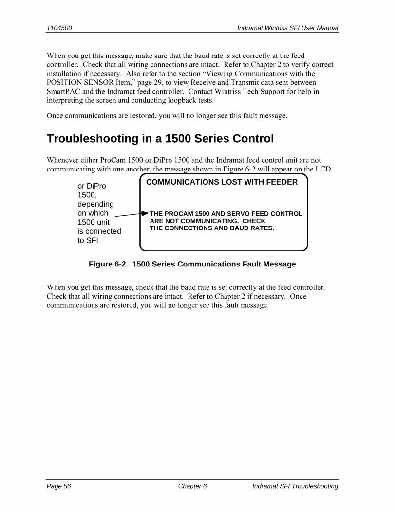
1104500 Indramat Wintriss SFI User Manual
Page 56 Chapter 6 Indramat SFI Troubleshooting
When you get this message, make sure that the baud rate is set correctly at the feed controller. Check that all wiring connections are intact. Refer to Chapter 2 to verify correct installation if necessary. Also refer to the section “Viewing Communications with the POSITION SENSOR Item,” page 29, to view Receive and Transmit data sent between SmartPAC and the Indramat feed controller. Contact Wintriss Tech Support for help in interpreting the screen and conducting loopback tests.
Once communications are restored, you will no longer see this fault message.
Troubleshooting in a 1500 Series Control
Whenever either ProCam 1500 or DiPro 1500 and the Indramat feed control unit are not communicating with one another, the message shown in Figure 6-2 will appear on the LCD.
THE PROCAM 1500 AND SERVO FEED CONTROLARE NOT COMMUNICATING. CHECKTHE CONNECTIONS AND BAUD RATES.
COMMUNICATIONS LOST WITH FEEDERor DiPro1500,dependingon which1500 unitis connectedto SFI
Figure 6-2. 1500 Series Communications Fault Message
When you get this message, check that the baud rate is set correctly at the feed controller. Check that all wiring connections are intact. Refer to Chapter 2 if necessary. Once communications are restored, you will no longer see this fault message.
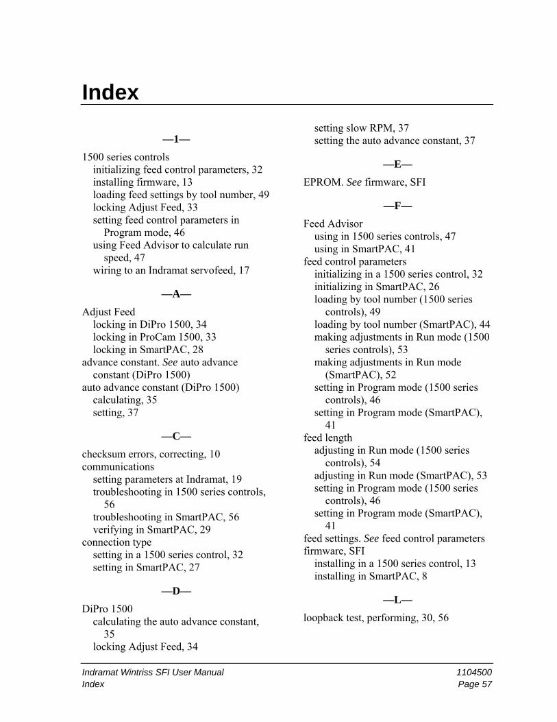
Indramat Wintriss SFI User Manual 1104500 Index Page 57
Index
—1—
1500 series controls initializing feed control parameters, 32 installing firmware, 13 loading feed settings by tool number, 49 locking Adjust Feed, 33 setting feed control parameters in
Program mode, 46 using Feed Advisor to calculate run
speed, 47 wiring to an Indramat servofeed, 17
—A—
Adjust Feed locking in DiPro 1500, 34 locking in ProCam 1500, 33 locking in SmartPAC, 28
advance constant. See auto advance constant (DiPro 1500)
auto advance constant (DiPro 1500) calculating, 35 setting, 37
—C—
checksum errors, correcting, 10 communications
setting parameters at Indramat, 19 troubleshooting in 1500 series controls,
56 troubleshooting in SmartPAC, 56 verifying in SmartPAC, 29
connection type setting in a 1500 series control, 32 setting in SmartPAC, 27
—D—
DiPro 1500 calculating the auto advance constant,
35 locking Adjust Feed, 34
setting slow RPM, 37 setting the auto advance constant, 37
—E—
EPROM. See firmware, SFI
—F—
Feed Advisor using in 1500 series controls, 47 using in SmartPAC, 41
feed control parameters initializing in a 1500 series control, 32 initializing in SmartPAC, 26 loading by tool number (1500 series
controls), 49 loading by tool number (SmartPAC), 44 making adjustments in Run mode (1500
series controls), 53 making adjustments in Run mode
(SmartPAC), 52 setting in Program mode (1500 series
controls), 46 setting in Program mode (SmartPAC),
41 feed length
adjusting in Run mode (1500 series controls), 54
adjusting in Run mode (SmartPAC), 53 setting in Program mode (1500 series
controls), 46 setting in Program mode (SmartPAC),
41 feed settings. See feed control parameters firmware, SFI
installing in a 1500 series control, 13 installing in SmartPAC, 8
—L—
loopback test, performing, 30, 56
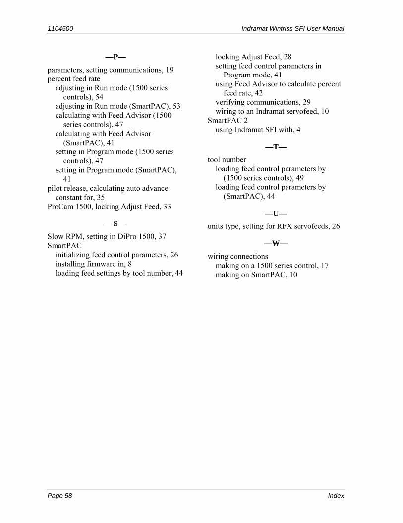
1104500 Indramat Wintriss SFI User Manual
Page 58 Index
—P—
parameters, setting communications, 19 percent feed rate
adjusting in Run mode (1500 series controls), 54
adjusting in Run mode (SmartPAC), 53 calculating with Feed Advisor (1500
series controls), 47 calculating with Feed Advisor
(SmartPAC), 41 setting in Program mode (1500 series
controls), 47 setting in Program mode (SmartPAC),
41 pilot release, calculating auto advance
constant for, 35 ProCam 1500, locking Adjust Feed, 33
—S—
Slow RPM, setting in DiPro 1500, 37 SmartPAC
initializing feed control parameters, 26 installing firmware in, 8 loading feed settings by tool number, 44
locking Adjust Feed, 28 setting feed control parameters in
Program mode, 41 using Feed Advisor to calculate percent
feed rate, 42 verifying communications, 29 wiring to an Indramat servofeed, 10
SmartPAC 2 using Indramat SFI with, 4
—T—
tool number loading feed control parameters by
(1500 series controls), 49 loading feed control parameters by
(SmartPAC), 44
—U—
units type, setting for RFX servofeeds, 26
—W—
wiring connections making on a 1500 series control, 17 making on SmartPAC, 10

Wintriss Manuals
Wintriss Manuals Wintriss Product
Installation Manual Doc. No.
User Manual/CD Doc. No.
AutoSet (1500, 1500 Plus, 1504, 1504 Plus) DA71747 DA71447
AutoSetPAC (Tonnage Monitor) DA71413 DA71443
Die Protection Handbook N.A. * 1130300 *
DiPro 1500 DA71428 DA71447
DSI 2 Sensor Interface N.A. * DA66970 *
LETS Machine Interface (LMI) N.A. ** DA71974 **
MultiPAC Types 1 and 2 DA71409 DA71443
MultiPAC Types 4 and 5 DA71410 DA71443
ProCam 1500 DA71430 DA71447
ProPAC (Process Monitor – In-die Measurement) DA71411 DA71443
RamPAC (Shut Height, Counterbalance & Cushion Control)
DA71412 DA71443
Servofeed Interface – Coe/Wintriss DA71415 DA71443
Servofeed Interface – CWP/Wintriss DA71416 DA71443
Servofeed Interface – DiPro DA71429 DA71447
Servofeed Interface – Electrocraft/Wintriss DA71417 DA71443
Servofeed Interface – Indramat/Wintriss DA71418 DA71443
Servofeed Interface – ProCam DA71431 DA71447
Servofeed Interface – SmartPAC DA71420 DA71443
Servofeed Interface – Waddington/Wintriss DA71419 DA71443
SFC Machine Interface (SMI) N.A. ** 1040800 **
Shadow V Safety Light Curtain DA71433 DA71449
Shadow VI Safety Light Curtain DA71422 DA71445
Shadow VII Safety Light Curtain N. A. * 1129400 *
Shadow 8 Safety Light Curtain N. A. * 1139300 *
SmartPAC (w/ DiProPAC & ProCamPAC) DA71439 DA71454
SmartPAC Hydraulic DA71435 DA71451
SmartPAC Run Mode (Spanish) N. A. * DA71443
SmartPAC w/ WPC II Integration DA71440 DA71455
SmartPAC 2 (w/ DiProPAC & ProCamPAC) DA71406 DA71441
SmartPAC 2 Hydraulic DA71436 DA71451
SmartPAC 2 Servo DA71437 DA71452
SmartPAC 2 w/ WPC 2000 Integration DA71407 DA71442
SmartPAC 2 w/WPC 2000 Run Mode (Spanish) N. A. * DA71443
WaveFormPAC (Advanced Load Analyzer) DA71414 DA71443
Wintriss Brake Monitor DA71432 DA71448
Wintriss Clock Display N. A. * DA67206 *
WPC II Wintriss Press Control DA71438 DA71453
WPC 1000 Wintriss Press Control DA71423 DA71446
WPC 2000 Wintriss Press Control DA71421 DA71444
WPC 2000 Option 2 DA71408 DA71442
* Installation Manual not available; User Manual available in hard copy only. Die Protection Handbook
available in hard copy (1102400) and on CD (1130300).
* Installation Manual not available. User Manual available on CD only.