
Why error compensation prohibited
13
ALATA TEKNIK UTAMA LINEAR ERROR CORRECTION A disadvantages concept but people do, because they DON’T KNOW...!!! Saraswanto Abdul Jabbar 12/21/2014 Most people think to do the correction of the linear error is an advantages, but actually they were wrong. To do the correction is not so simple as they think. This white paper will answer the correct reason.
-
Upload
saraswanto-abduljabbar -
Category
Engineering
-
view
59 -
download
3
Transcript of Why error compensation prohibited
ALATA TEKNIK UTAMA
LINEAR ERRORCORRECTION
A disadvantages concept but people do, becausethey DON’T KNOW...!!!
Saraswanto Abdul Jabbar
12/21/2014
Most people think to do the correction of the linear error is an advantages, but actually they werewrong. To do the correction is not so simple as they think. This white paper will answer the correctreason.
1
CONTENTS:
1. Preface 2
2. PHYSICAL AND THERMAL PROPERTIES OF ULMs 4
3. TOLERANCE GRADE FOR GAUGE BLOCKS 7
4. ERROR FROM ELASTIC PROPERTIES 7
4.1 CASCADING ERRORS 8
4.1.1 ERROR caused of Elasticity Machine BED 9
4.1.2 Cosine and Sine Errors 10
4.2 Contact Deformation in Mechanical Comparisons 10
5. CONCLUTION 11
2
1. PREFACE
Many manufacturer produce the measuring machines with fitur LINEAR ERROR
COMPENSATION. Yes, this concept will help measurement will be done faster then
without compensation. Do you think this concept is correct? Lets we see the actual
world.
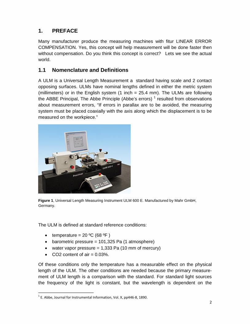
1.1 Nomenclature and Definitions
A ULM is a Universal Length Measurement a standard having scale and 2 contact
opposing surfaces. ULMs have nominal lengths defined in either the metric system
(millimeters) or in the English system (1 inch = 25.4 mm). The ULMs are following
the ABBE Principal, The Abbe Principle (Abbe’s errors) 1 resulted from observations
about measurement errors, “If errors in parallax are to be avoided, the measuring
system must be placed coaxially with the axis along which the displacement is to be
measured on the workpiece.”
Figure 1, Universal Length Measuring Instrument ULM 600 E. Manufactured by Mahr GmbH,
Germany.
The ULM is defined at standard reference conditions:
temperature = 20 ºC (68 ºF )
barometric pressure = 101,325 Pa (1 atmosphere)
water vapor pressure = 1,333 Pa (10 mm of mercury)
CO2 content of air = 0.03%.
Of these conditions only the temperature has a measurable effect on the physical
length of the ULM. The other conditions are needed because the primary measure-
ment of ULM length is a comparison with the standard. For standard light sources
the frequency of the light is constant, but the wavelength is dependent on the
1E. Abbe, Journal for Instrumental Information, Vol. X, pp446-8, 1890.
3
temperature, pressure, humidity, and COଶ content of the air. These effects are
described in detail later.
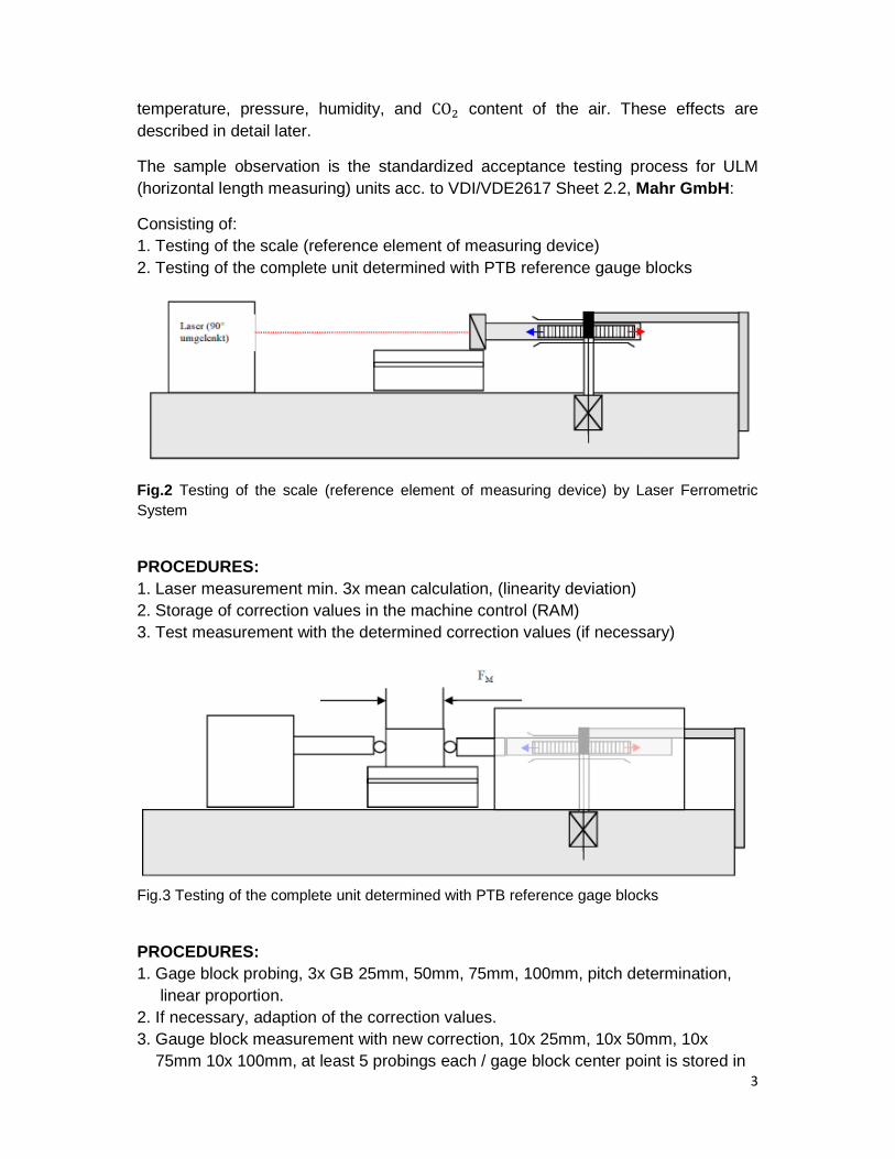
The sample observation is the standardized acceptance testing process for ULM
(horizontal length measuring) units acc. to VDI/VDE2617 Sheet 2.2, Mahr GmbH:
Consisting of:
1. Testing of the scale (reference element of measuring device)
2. Testing of the complete unit determined with PTB reference gauge blocks
Fig.2 Testing of the scale (reference element of measuring device) by Laser Ferrometric
System
PROCEDURES:
1. Laser measurement min. 3x mean calculation, (linearity deviation)
2. Storage of correction values in the machine control (RAM)
3. Test measurement with the determined correction values (if necessary)
Fig.3 Testing of the complete unit determined with PTB reference gage blocks
PROCEDURES:
1. Gage block probing, 3x GB 25mm, 50mm, 75mm, 100mm, pitch determination,
linear proportion.
2. If necessary, adaption of the correction values.
3. Gauge block measurement with new correction, 10x 25mm, 10x 50mm, 10x
75mm 10x 100mm, at least 5 probings each / gage block center point is stored in
4
The calibration certificate. Testing of repeatability range ≤ 0.02µm, first
Commissioning by manufacturer, max. 0.03µm for ULM 600E and Testing of
repeatability range ≤ 0.05µm, first commissioning by manufacturer, max. 0.09µm.
NOTE:
Due to the critical set-up for compliance to the requirement of the standard
calibration, thus the correction only acceptable in the condition according to
paragraph 1.1. Beside this, we also must calculated using statistical methode
according to ISO/GUM. In the previous machines of the ULMs, Mahr also provieded
the Linear Error Correction protected by PASSWORD. But in the reality for the
longterm process, the ULM the accuracy become worst
2. PHYSICAL AND THERMAL PROPERTIES OF ULMs
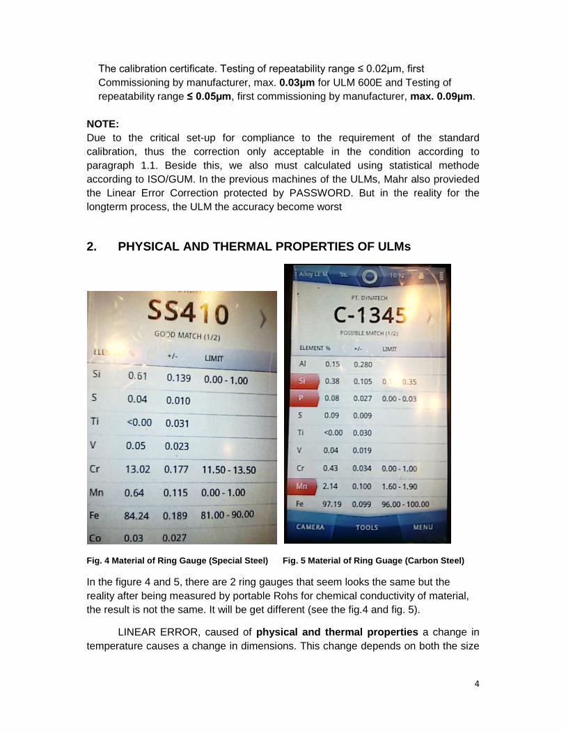
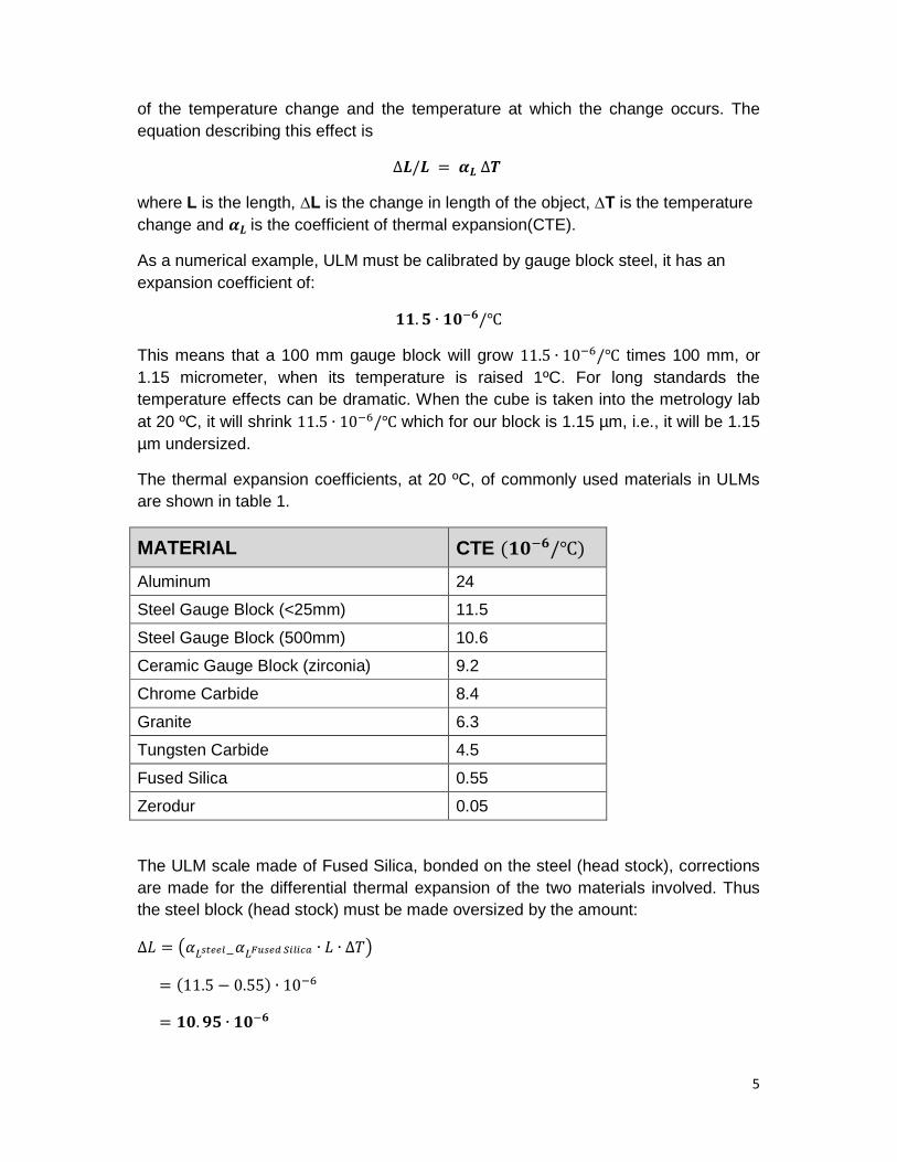
Fig. 4 Material of Ring Gauge (Special Steel) Fig. 5 Material of Ring Guage (Carbon Steel)
In the figure 4 and 5, there are 2 ring gauges that seem looks the same but the
reality after being measured by portable Rohs for chemical conductivity of material,
the result is not the same. It will be get different (see the fig.4 and fig. 5).
LINEAR ERROR, caused of physical and thermal properties a change in
temperature causes a change in dimensions. This change depends on both the size
5
of the temperature change and the temperature at which the change occurs. The
equation describing this effect is
ࢻ�=�/∆ �∆
where L is the length, ∆L is the change in length of the object, ∆T is the temperature
change and ࢻ is the coefficient of thermal expansion(CTE).
As a numerical example, ULM must be calibrated by gauge block steel, it has an
expansion coefficient of:
. ∙ /℃
This means that a 100 mm gauge block will grow 11.5 ∙ 10/℃ times 100 mm, or
1.15 micrometer, when its temperature is raised 1ºC. For long standards the
temperature effects can be dramatic. When the cube is taken into the metrology lab
at 20 ºC, it will shrink 11.5 ∙ 10/℃ which for our block is 1.15 µm, i.e., it will be 1.15
µm undersized.
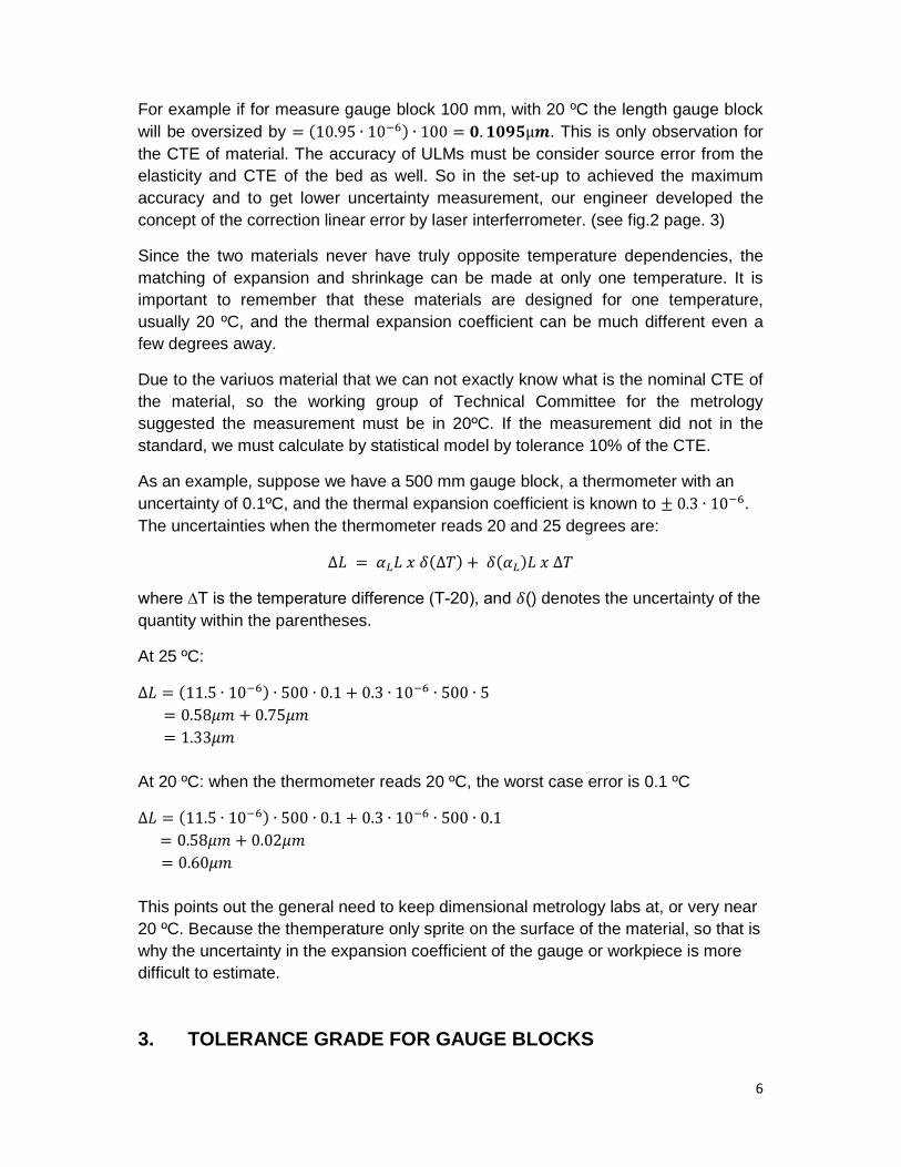
The thermal expansion coefficients, at 20 ºC, of commonly used materials in ULMs
are shown in table 1.
MATERIAL CTE (/℃)
Aluminum 24
Steel Gauge Block (<25mm) 11.5
Steel Gauge Block (500mm) 10.6
Ceramic Gauge Block (zirconia) 9.2
Chrome Carbide 8.4
Granite 6.3
Tungsten Carbide 4.5
Fused Silica 0.55
Zerodur 0.05
The ULM scale made of Fused Silica, bonded on the steel (head stock), corrections
are made for the differential thermal expansion of the two materials involved. Thus
the steel block (head stock) must be made oversized by the amount:
=ܮ∆ ൫ߙೞ ಷೠೞ�ೄߙ ∙ ܮ ∙ ∆൯
= (11.5 − 0.55) ∙ 10
= . ∙
6
For example if for measure gauge block 100 mm, with 20 ºC the length gauge block
will be oversized by = (10.95 ∙ 10) ∙ 100 = .μ . This is only observation for
the CTE of material. The accuracy of ULMs must be consider source error from the
elasticity and CTE of the bed as well. So in the set-up to achieved the maximum
accuracy and to get lower uncertainty measurement, our engineer developed the
concept of the correction linear error by laser interferrometer. (see fig.2 page. 3)
Since the two materials never have truly opposite temperature dependencies, the
matching of expansion and shrinkage can be made at only one temperature. It is
important to remember that these materials are designed for one temperature,
usually 20 ºC, and the thermal expansion coefficient can be much different even a
few degrees away.
Due to the variuos material that we can not exactly know what is the nominal CTE of
the material, so the working group of Technical Committee for the metrology
suggested the measurement must be in 20ºC. If the measurement did not in the
standard, we must calculate by statistical model by tolerance 10% of the CTE.
As an example, suppose we have a 500 mm gauge block, a thermometer with an
uncertainty of 0.1ºC, and the thermal expansion coefficient is known to ± 0.3 ∙ 10.
The uncertainties when the thermometer reads 20 and 25 degrees are:
(∆)ߜ�ݔ�ܮߙ�=�ܮ∆ + ∆�ݔ�ܮ(ߙ)ߜ�
where ∆T is the temperature difference (T-20), and ߜ() denotes the uncertainty of the
quantity within the parentheses.
At 25 ºC:
=ܮ∆ (11.5 ∙ 10) ∙ 500 ∙ 0.1 + 0.3 ∙ 10 ∙ 500 ∙ 5
= ߤ0.58 + ߤ0.75
= ߤ1.33
At 20 ºC: when the thermometer reads 20 ºC, the worst case error is 0.1 ºC
=ܮ∆ (11.5 ∙ 10) ∙ 500 ∙ 0.1 + 0.3 ∙ 10 ∙ 500 ∙ 0.1
= ߤ0.58 + ߤ0.02
= ߤ0.60
This points out the general need to keep dimensional metrology labs at, or very near
20 ºC. Because the themperature only sprite on the surface of the material, so that is
why the uncertainty in the expansion coefficient of the gauge or workpiece is more
difficult to estimate.
3. TOLERANCE GRADE FOR GAUGE BLOCKS
7
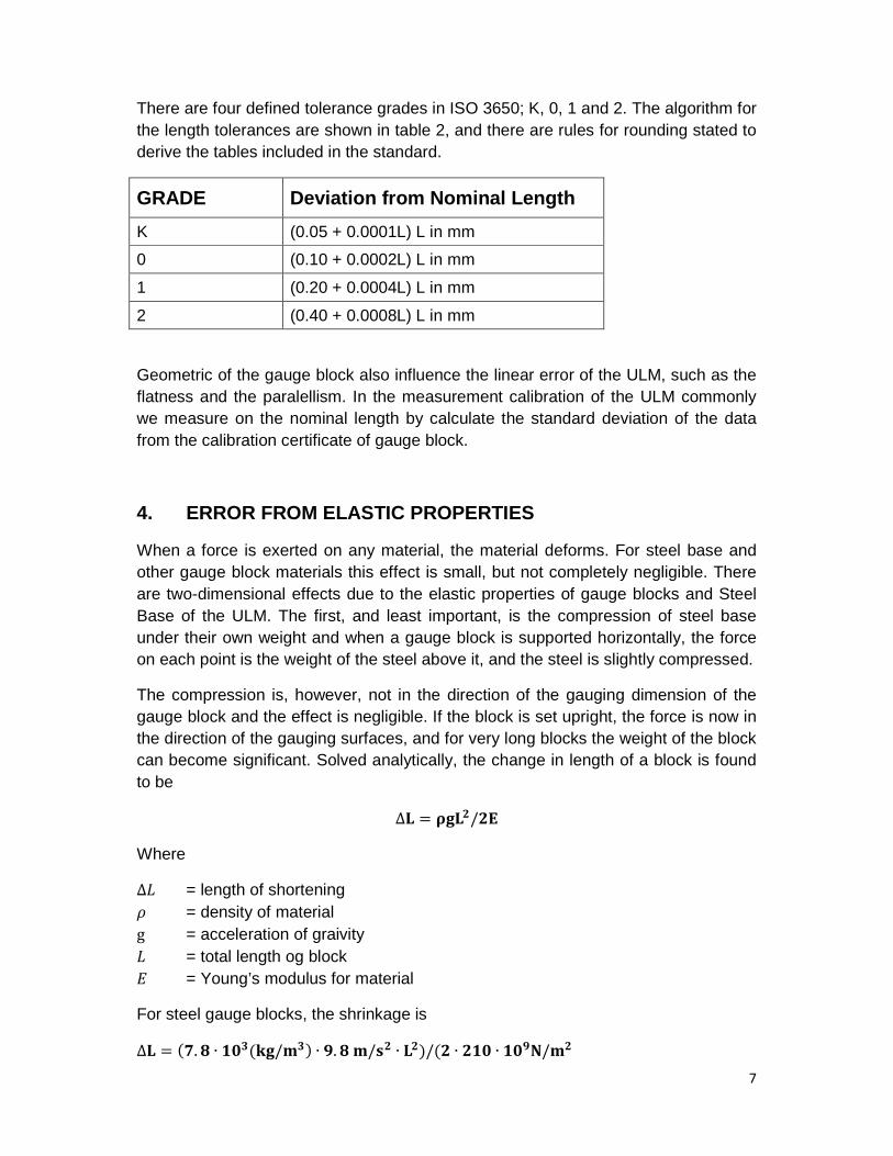
There are four defined tolerance grades in ISO 3650; K, 0, 1 and 2. The algorithm for
the length tolerances are shown in table 2, and there are rules for rounding stated to
derive the tables included in the standard.
GRADE Deviation from Nominal Length
K (0.05 + 0.0001L) L in mm
0 (0.10 + 0.0002L) L in mm
1 (0.20 + 0.0004L) L in mm
2 (0.40 + 0.0008L) L in mm
Geometric of the gauge block also influence the linear error of the ULM, such as the
flatness and the paralellism. In the measurement calibration of the ULM commonly
we measure on the nominal length by calculate the standard deviation of the data
from the calibration certificate of gauge block.
4. ERROR FROM ELASTIC PROPERTIES
When a force is exerted on any material, the material deforms. For steel base and
other gauge block materials this effect is small, but not completely negligible. There
are two-dimensional effects due to the elastic properties of gauge blocks and Steel
Base of the ULM. The first, and least important, is the compression of steel base
under their own weight and when a gauge block is supported horizontally, the force
on each point is the weight of the steel above it, and the steel is slightly compressed.
The compression is, however, not in the direction of the gauging dimension of the
gauge block and the effect is negligible. If the block is set upright, the force is now in
the direction of the gauging surfaces, and for very long blocks the weight of the block
can become significant. Solved analytically, the change in length of a block is found
to be
=ۺ∆ ૉۺ/۳
Where
�ܮ∆ = length of shortening
ߩ = density of material
g = acceleration of graivity
ܮ = total length og block
ܧ = Young’s modulus for material
For steel gauge blocks, the shrinkage is
=ۺ∆ (ૠ.ૡ ∙ (ܕ/ܓ ) ∙ .ૡܕ� ܛ/ ∙ )/(ۺ ∙ ∙ ܕ/ۼ
8
= .ૡ ∙ ∙ in meters.
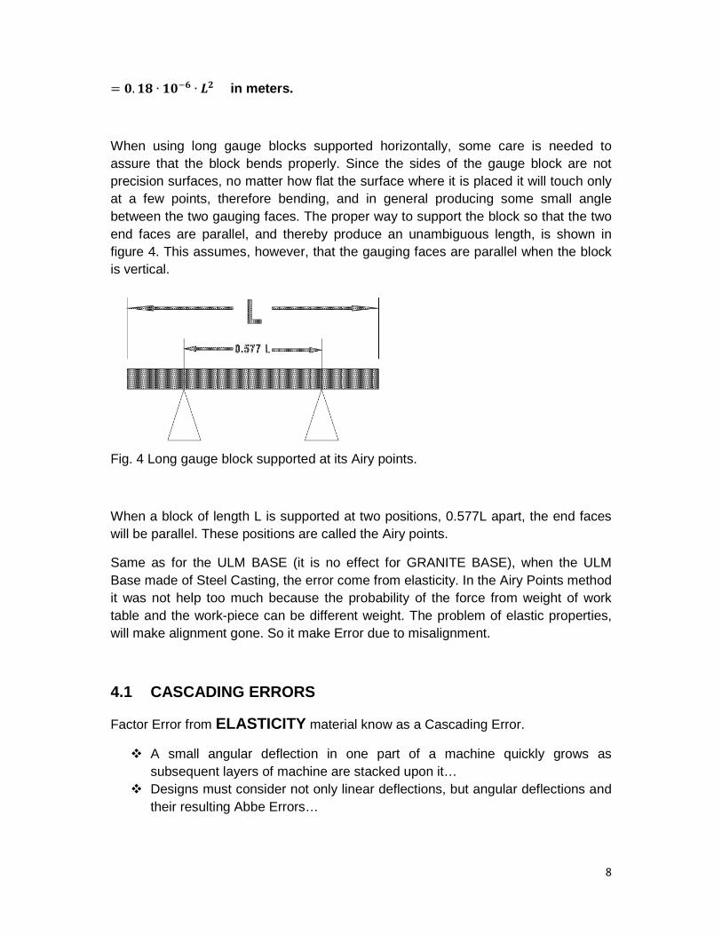
When using long gauge blocks supported horizontally, some care is needed to
assure that the block bends properly. Since the sides of the gauge block are not
precision surfaces, no matter how flat the surface where it is placed it will touch only
at a few points, therefore bending, and in general producing some small angle
between the two gauging faces. The proper way to support the block so that the two
end faces are parallel, and thereby produce an unambiguous length, is shown in
figure 4. This assumes, however, that the gauging faces are parallel when the block
is vertical.
Fig. 4 Long gauge block supported at its Airy points.
When a block of length L is supported at two positions, 0.577L apart, the end faces
will be parallel. These positions are called the Airy points.
Same as for the ULM BASE (it is no effect for GRANITE BASE), when the ULM
Base made of Steel Casting, the error come from elasticity. In the Airy Points method
it was not help too much because the probability of the force from weight of work
table and the work-piece can be different weight. The problem of elastic properties,
will make alignment gone. So it make Error due to misalignment.
4.1 CASCADING ERRORS
Factor Error from ELASTICITY material know as a Cascading Error.
A small angular deflection in one part of a machine quickly grows as
subsequent layers of machine are stacked upon it…
Designs must consider not only linear deflections, but angular deflections and
their resulting Abbe Errors…
9
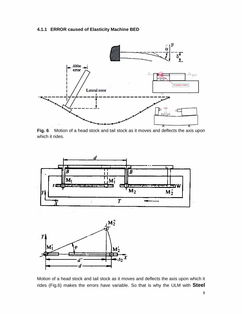
4.1.1 ERROR caused of Elasticity Machine BED
Fig. 6 Motion of a head stock and tail stock as it moves and deflects the axis upon
which it rides.
Motion of a head stock and tail stock as it moves and deflects the axis upon which it
rides (Fig.6) makes the errors have variable. So that is why the ULM with Steel
10
Casting make variable error too high. And the result can be found as calculation
below:
∆= − =ᇱ −) ( ≈
Example:
If = � ���, = ",������∆= .× = .�
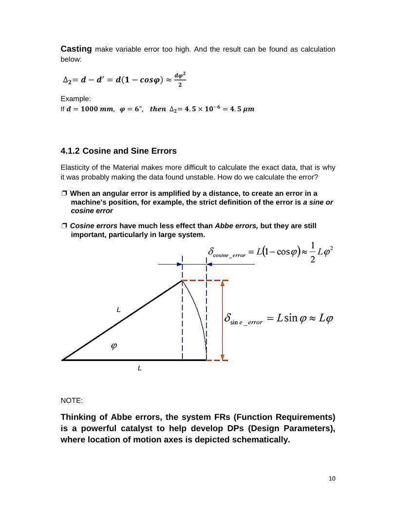
4.1.2 Cosine and Sine Errors
Elasticity of the Material makes more difficult to calculate the exact data, that is why
it was probably making the data found unstable. How do we calculate the error?
❐ When an angular error is amplified by a distance, to create an error in amachine’s position, for example, the strict definition of the error is a sine orcosine error
❐ Cosine errors have much less effect than Abbe errors, but they are stillimportant, particularly in large system.
NOTE:
Thinking of Abbe errors, the system FRs (Function Requirements)
is a powerful catalyst to help develop DPs (Design Parameters),
where location of motion axes is depicted schematically.
11
4.2 Contact Deformation in Mechanical Comparisons
Nearly all the Universal length measurements of objects with gauge blocks are made
with contact type where a probe tip contacts a surface under an applied force.
Contact between a spherical tip and a plane surface results in local deformation of
small but significant magnitude. If the gauge blocks or objects being compared are
made of the same material, the measured length difference between them will be
correct, since the deformation in each case will be the same. If the materials are
different, the length difference will be incorrect by the difference in the amount of
deformation for the materials. In such cases, a deformation correction may be
applied if its magnitude is significant to the measurement.
Total deformation (probe plus object) is a function of the geometry and elastic
properties of the two contacting surfaces, and contact force. Hertz [21] developed
formulas for total uniaxial deformation based on the theory of elasticity and by
assuming that the bodies are isotropic, that there is no tangential force at contact,
and that the elastic limit is not exceeded in the contact area. Many experimenters
[22, 23] have verified the reliability of the Hertzian formulas. The formulas given
below are from a CSIRO (Australian metrology laboratory) publication that contains
formulas for a number of combinations of geometric contact between planes,
cylinders and spheres [24].
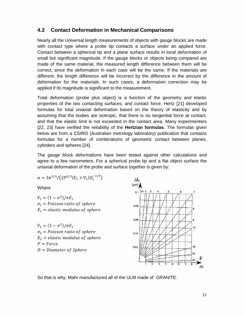
The gauge block deformations have been tested against other calculations and
agree to a few nanometers. For a spherical probe tip and a flat object surface the
uniaxial deformation of the probe and surface together is given by:
ߙ = )ଶ/ଷ/൫2ଶ/ଷߨ3 ଵ + ଶ)ܦଵଵ/ଷ
൯
Where
ଵ = (1 − ଵܧߨ/(ଶߪଵߪ = ݏݏ ݎ� �ݐ ℎݏ� ݎ
ଵܧ = ݐݏ � ݑ �ݏݑ ℎݏ� ݎ
ଶ = (1 − ଵܧߨ/(ଶߪଶߪ = ݏݏ ݎ� �ݐ ℎݏ� ݎ
ଶܧ = ݐݏ � ݑ �ݏݑ ℎݏ� ݎ
= ݎܨ
ܦ = ܦ ݐ �ݎ ℎ� ݎ
So that is why, Mahr manufactured all of the ULM made of GRANITE.
12
5. CONCLUTION:
Mahr has more than 150 years experienced in metrology, especially for the ULM,
previously Mahr produce the ULM with steel casting base. More and more the
technology required submicron measurement even Nano. For those reason, Mahr
produce the new concept by using HARD ROCK NATURAL GRANITE, where this
material has superior charachtersitic compare to Steel Casting.
Mahr use the new concept by make design that the measurement accuracy have
been done in Mahr measuring laboratory in Germany. So user is not necessary to do
linear error compensation any more. The linear error compensation will not be
accepted because a lot of factors will make error measurement, such as:
a. Uncertainty measurement caused the measuring machine.
These can be geometrik of the contact tip, scale, machine base, etc.
b. Uncertainty due to reversal point (misalignment).
c. Uncertainty due to NOT EXACT knowledge of the CTE material.
- The bigger size of the material make the CTE became systematically smaller
- The themperatur also only sprite on the surface of the material. So that is
why the correction of the themperatur is no help to much.
d. Uncertainty factor due to the elasticity of the material such as base machine
during the measuring procedure.
Reference:
1. Ted Doiron and John Beers, “The Gauge Block Handbook”, Dimensional
Metrology Group Precision Engineering Division National Institute of Standards and
Technology,
2. Puttock, M.J. and E.G. Thwaite, "Elastic Compression of Spheres and Cylinders at
Point and Line Contact," Natoinal Standards Laboratory Technical Paper No. 25,
CSIRO, 1969.
3. Beers, J.S. and J.E. Taylor. "Contact deformation in Gauge Block Comparisons,"
NBS Technical Note 962, 1978.


