![Pile Foundation Design[1] - ITDmtp.itd.co.th/ITD-CP/data/PileFoundationDesign.pdf · Introduction to pile foundations Pile foundation design Load on piles Single pile design Pile](https://static.fdocuments.in/doc/165x107/5a6ffb387f8b9ab1538b8376/pile-foundation-design1-itdmtpitdcothitd-cpdatapilefoundationdesignpdfpdf.jpg)
Why do we need to worry about unbraced pile design?
58
Structural Analysis of Unbraced Piles 2/16/2016 1 Structural Analysis of Unbraced Piles February 16, 2016 INDOT Bridge Design Conference - 2016 Structural Analysis of Unbraced Piles Why do we need to worry about unbraced pile design?
Transcript of Why do we need to worry about unbraced pile design?

Structural Analysis of Unbraced Piles 2/16/2016
1
Structural Analysis of Unbraced Piles
February 16, 2016
INDOT Bridge DesignConference - 2016
Structural Analysis of Unbraced Piles
Why do we need to worry about unbraced pile design?

Structural Analysis of Unbraced Piles 2/16/2016
2
Structural Analysis of Unbraced Piles
Why do we need to worry about unbraced pile design?
Structural Analysis of Unbraced Piles

Structural Analysis of Unbraced Piles 2/16/2016
3
Structural Analysis of Unbraced Piles
Geotechnical Capacity
Vs.
Structural Pile Capacity
Structural Analysis of Unbraced Piles
• Geotechnical Pile Capacity:– Pile capacity through soil resistance
– Soil resistance will consist of skin friction capacity and/or end bearing capacity
– Pile capacities and recommendations will be given in a Geotechnical Report
– Maximum pile reaction will be calculated with applied axial force and additional forces due to moments for Strength and Extreme Load Cases

Structural Analysis of Unbraced Piles 2/16/2016
4
Structural Analysis of Unbraced Piles
• Structural Pile Capacity:– Steel pile capacity calculated in Section 6 of
the AASTHO LRFD Bridge Design Specifications
– Section 6.9 addresses Compression Members
– Combined Axial Compression and Flexure Section 6.9.2.2
When will I need to design for an unbraced pile length?
IDM: Section 408-6.0

Structural Analysis of Unbraced Piles 2/16/2016
5
When will I need to design for an unbraced pile length?
IDM: Figure 408-3D
When will I need to design for an unbraced pile length?
Do I need to design for scour if my pier is not in the waterway?
YES
BUT…….

Structural Analysis of Unbraced Piles 2/16/2016
6
When will I need to design for an unbraced pile length?
Do I need to design for scour if my pier is not in the waterway?
CONTACT INDOT HYDRAULICS IF ANY
EXCEPTIONS CAN BE MADE.
THIS WILL BE HANDLED ON A CASE BY CASE BASIS!
When will I need to design for an unbraced pile length?
Why do I need to design for scour if my pier is not in the waterway?
Waterways can change geometry over time:

Structural Analysis of Unbraced Piles 2/16/2016
7
Design of Pile Bent Foundation
Friction Piles
Design of Pile Bent Foundation
Friction Piles

Structural Analysis of Unbraced Piles 2/16/2016
8
Design of Pile Bent Foundation
Point Bearing
Design of Pile Bent Foundation
Point Bearing

Structural Analysis of Unbraced Piles 2/16/2016
9
Design of Piers with Footings
Friction Piles
Design of Piers with Footings
Friction Piles

Structural Analysis of Unbraced Piles 2/16/2016
10
Design of Piers with Footings
Friction Piles
Design of Piers with Footings
Point Bearing

Structural Analysis of Unbraced Piles 2/16/2016
11
Design of Piers with Footings
Point Bearing
Design of Piers with Footings
Point Bearing

Structural Analysis of Unbraced Piles 2/16/2016
12
Design of Wall Piers
Friction / Point Bearing
Design of Wall Piers
Friction Piles

Structural Analysis of Unbraced Piles 2/16/2016
13
Design of Wall Piers
Friction Piles
Design of Wall Piers
Point Bearing

Structural Analysis of Unbraced Piles 2/16/2016
14
Design of Wall Piers
Point Bearing
Structural Design of Pile
Check Combined Axial Compression and FlexureAASHTO LRFD Section: 6.9.2.2
- Slenderness Ratio:/ 120 (Section 6.9.3)
- If Pu/Pr < 0.2, then
1.0 (6.9.2.2-1)
- If Pu/Pr > 0.2, then
.
.1.0 (6.9.2.2-1)
Structural Analysis of Unbraced Piles 2/16/2016
15
Structural Design of Pile
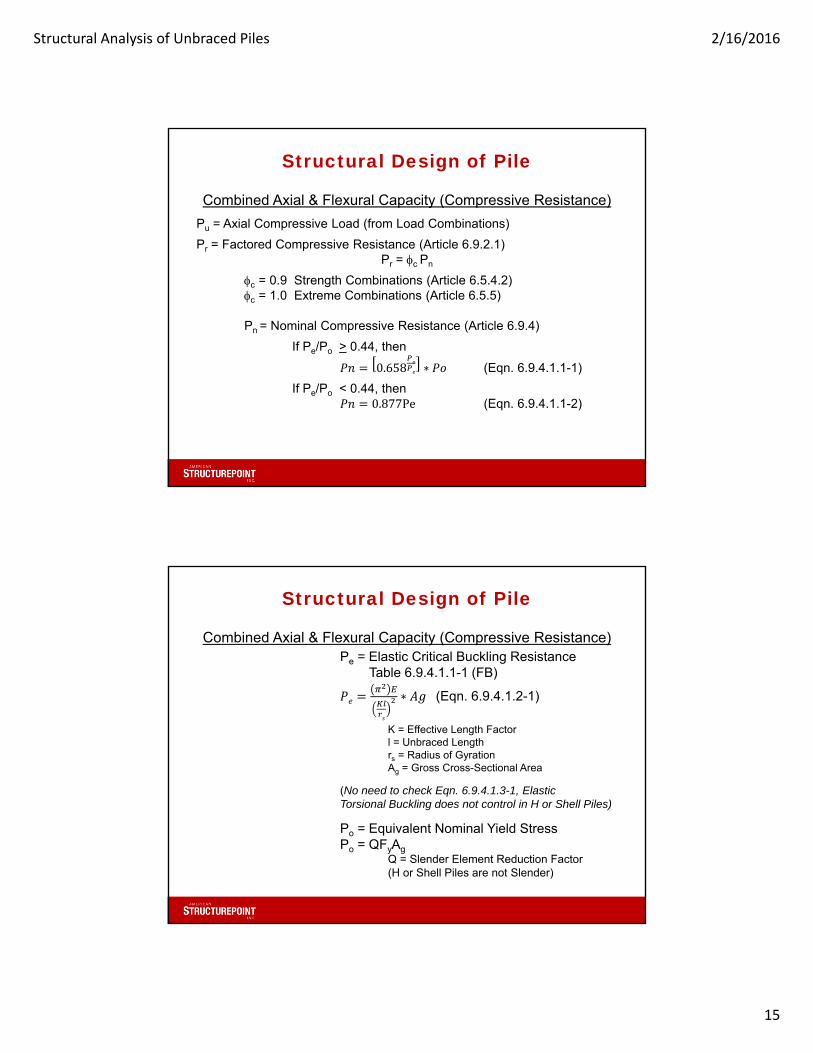
Combined Axial & Flexural Capacity (Compressive Resistance)
Pu = Axial Compressive Load (from Load Combinations)
Pr = Factored Compressive Resistance (Article 6.9.2.1)Pr = c Pn
c = 0.9 Strength Combinations (Article 6.5.4.2)c = 1.0 Extreme Combinations (Article 6.5.5)
Pn = Nominal Compressive Resistance (Article 6.9.4)
If Pe/Po > 0.44, then
0.658 ∗ (Eqn. 6.9.4.1.1-1)
If Pe/Po < 0.44, then0.877Pe (Eqn. 6.9.4.1.1-2)
Structural Design of Pile
Combined Axial & Flexural Capacity (Compressive Resistance)Pe = Elastic Critical Buckling Resistance
Table 6.9.4.1.1-1 (FB)
∗ (Eqn. 6.9.4.1.2-1)
K = Effective Length Factorl = Unbraced Lengthrs = Radius of GyrationAg = Gross Cross-Sectional Area
(No need to check Eqn. 6.9.4.1.3-1, Elastic Torsional Buckling does not control in H or Shell Piles)
Po = Equivalent Nominal Yield StressPo = QFyAg
Q = Slender Element Reduction Factor(H or Shell Piles are not Slender)

Structural Analysis of Unbraced Piles 2/16/2016
16
Structural Analysis of Unbraced Piles
Combined Axial & Flexural Capacity (Flexural Resistance)
Back to Combined Axial & Flexural Capacity Equations:
1.0 (6.9.2.2-1)
.
.1.0 (6.9.2.2-2)
Mux = Factored Flexural Moment about x-axis (Strong-Axis)
Muy = Factored Flexural Moment about y-axis (Weak-Axis)(Obtained from Strength & Extreme Load Combinations)
Mrx = Factored Flexural Resistance about x-axis (Strong-Axis) = fMnc
Mry = Factored Flexural Resistance about y-axis (Weak-Axis) = fMn
Structural Analysis of Unbraced Piles
Flexural Resistance Due to FLB (Strong Axis)
To Calculate Mrx (Strong Axis): Both Flange Local Buckling (FLB) and Lateral Torsional Buckling (LTB) need to be calculated.
FLB:Check Section Ratios (A6.3.2):
Slenderness Ratio for Compression Flange: f
bfc: Compression Flange Width
tfc: Compression Flange Thickness
Limiting Slenderness Ratio for Compact Flange: pf = 0.38
E: Young’s Modulus
Fyc: Yield Strength of Compression Flange

Structural Analysis of Unbraced Piles 2/16/2016
17
Structural Analysis of Unbraced Piles
Flexural Resistance Due to FLB (Strong Axis)FLB:
Check Section Ratios (A6.3.2):
Limiting Slenderness Ratio for Noncompact Flange: rf = 0.95
kc: Flange local buckling coefficient (for rolled shapes = 0.76)
Fyr: Compression-flange stress at the onset of nominal yielding within cross-section
Fyr: taken as the smaller of: - 0.7Fyc
- ∗
- Fyw
- (But Not Less than 0.5Fyc)
Fyc: Yield Strength of Compression Flange
Rh: Hybrid Factor = 1.0
Fyt: Yield Strength of Tension Flange
Sxt: Elastic Sect Modulus with respect to strong-axis tension flange
Sxc: Elastic Sect Modulus with respect to strong-axis compress flange
Fyw: Yield Strength of Web
Structural Analysis of Unbraced Piles
Flexural Resistance Due to FLB (Strong Axis)
FLB:
Calculate Flexural Resistance based on Compression Flange Local Buckling:
if f < pf, then:
Mnc = RpcMyc (Eqn. A6.3.2-1)
Otherwise:
1 1f −
pfrf −
pf)]RpcMyc (Eqn. A6.3.2-2)
Rpc: Web Plastification Factor for Comp. Flange
For rolled I-Shapes, Rpc = Shape Factor
Shape Factor = Zx / Sx (Approx 1.10)
Myc: Yield Moment = FySx

Structural Analysis of Unbraced Piles 2/16/2016
18
Structural Analysis of Unbraced Piles
Flexural Resistance Due to LTB (Strong Axis)LTB:Calculate Plastic Length Limit (Lp) and Elastic Length Limit (Lr):Section A6.3.3
1.0 (Eqn. A6.3.3-4)
E: Young’s ModulusFyc: Yield Strength of Compression Flange rt: Effective radius of gyration for lateral torsional buckling
(Eqn. A6.3.3-10)
bfc: Compression Flange Width` tfc: Compression Flange Thickness
Dc: Depth of Webtw: Web Thickness
Structural Analysis of Unbraced Piles
Flexural Resistance Due to LTB (Strong Axis)LTB:Calculate Plastic Length Limit (Lp) and Elastic Length Limit (Lr):Section A6.3.3
1.95 1 1 6.76 ∗2
(Eqn. A6.3.3-5)
Sxc: Elastic Section Modulus about Strong Axish: Depth between centerline of flangesFyr: Yield Strength of Compression Flange
Fyr: taken as the smaller of: - 0.7Fyc
- ∗- Fyw
- (But Not Less than 0.5Fyc)
J: St. Venant torsional constant (Eqn. A6.3.3-9)
1 0.63 1 0.63

Structural Analysis of Unbraced Piles 2/16/2016
19
Structural Analysis of Unbraced Piles
Flexural Resistance Due to LTB (Strong Axis)
LTB:- The Limit Lengths of Lp and Lr have been calculated.
- Compare where the unbraced length, Lb, is in relation to Lp and Lr.
If Lb < Lp,
Mnc = RpcMyc (Eqn. A6.3.3-1)
Rpc: Web Plastification Factor for Comp. FlangeFor rolled I-Shapes, Rpc = Shape Factor
Shape Factor = Zx / Sx (Approx 1.10)
Myc: Yield Moment = FySx
Structural Analysis of Unbraced Piles
Flexural Resistance Due to LTB (Strong Axis)
LTB:If Lp < Lb < Lr,
1 1 (Eqn. A6.3.3-2)
Fyr: taken as the smaller of: - 0.7Fyc
- ∗
- Fyw
- (But Not Less than 0.5Fyc)
Rpc: Web Plastification Factor for Comp. FlangeFor rolled I-Shapes, Rpc = Shape Factor
Shape Factor = Zx / Sx (Approx 1.10)
Myc: Yield Moment = FySx
Sxc: Elastic Section Modulus about Strong Axis
Cb: Moment Gradient Modifier (Eqn. A6.3.3-6)

Structural Analysis of Unbraced Piles 2/16/2016
20
Structural Analysis of Unbraced Piles
Flexural Resistance Due to LTB (Strong Axis)
LTB:Moment Gradient Modifier, Cb:
For an Unbraced Cantilever, Cb = 1.0 (Eqn. A6.3.3-6)
For all other cases:
1.75 1.05 0.32
2.3 (Eqn. A6.3.3-2)
M1: Moment at brace point opposite to M2
M2: Largest Moment at either end of the unbraced length
Structural Analysis of Unbraced Piles
Flexural Resistance Due to LTB (Strong Axis)
LTB:If Lb > Lr,
Mnc = FcrSxc < RpcMyc (Eqn. A6.3.3-3)
Rpc: Web Plastification Factor for Comp. FlangeFor rolled I-Shapes, Rpc = Shape Factor
Shape Factor = Zx / Sx (Approx 1.10)
Myc: Yield Moment = FySx
Sxc: Elastic Section Modulus about Strong Axis
Fcr: Elastic Lateral Torsional Buckling Stress
1 0.0782
(Eqn. A6.3.3-8)

Structural Analysis of Unbraced Piles 2/16/2016
21
Structural Analysis of Unbraced Piles
Flexural Capacity (Mrx, Strong Axis)
Flexural Resistance based on compression flange local buckling has been calculated.
- Compare the values of Mnc for FLB and LTB
- The lower value of Mnc will be used
- Mrx = fMnc
1.0 (6.9.2.2-1)
.
.1.0 (6.9.2.2-2)
Structural Analysis of Unbraced Piles
Flexural Capacity (Mry, Weak Axis)
Flexural Resistance for Weak Axis (Section 6.12.2.2)
- LTB does not control
- FLB controls and needs to be checked
- Mry = fMn
1.0 (6.9.2.2-1)
.
.1.0 (6.9.2.2-2)

Structural Analysis of Unbraced Piles 2/16/2016
22
Structural Analysis of Unbraced Piles
Flexural Resistance Due to FLB (Weak Axis)
FLB:
Check Section Ratios (Article 6.12.2.2):
Slenderness Ratio for Flange: f
bf: Flange Width
tf: Flange Thickness
Limiting Slenderness Ratio for Compact Flange: pf = 0.38
E: Young’s Modulus
Fyf: Yield Strength of Flange
Structural Analysis of Unbraced Piles
Flexural Resistance Due to FLB (Weak Axis)
FLB:
Check Section Ratios (Article 6.12.2.2):
Limiting Slenderness Ratio for Noncompact Flange: rf = 0.83
E: Young’s Modulus
Fyf: Yield Strength of Flange

Structural Analysis of Unbraced Piles 2/16/2016
23
Structural Analysis of Unbraced Piles
Flexural Resistance Due to FLB (Weak Axis)FLB:Calculate Flexural Resistance based on Flange Local Buckling:
if f < pf, then:Mn = Mp (Eqn. 6.12.2.2.1-1)
Mp = FyfZy
Fyf: Yield Strength of Flange
Zy: Plastic Section Modulus about Weak-Axis
Structural Analysis of Unbraced Piles
Flexural Resistance Due to FLB (Weak Axis)
FLB:
Calculate Flexural Resistance based on Flange Local Buckling:
if pf < f < rf then:
1 1f pf
.(Eqn. 6.12.2.2.1-2)
Sy: Section Modulus about Weak-Axis
E: Young’s Modulus
Fyf: Yield Strength of Flange
Zy: Plastic Section Modulus about Weak-Axis

Structural Analysis of Unbraced Piles 2/16/2016
24
Structural Analysis of Unbraced Piles
Flexural Capacity (Mry, Weak Axis)
Flexural Resistance based on weak-axis bending.
- Mry = fMn
1.0 (6.9.2.2-1)
.
.1.0 (6.9.2.2-2)
Structural Design of Pile
Check Combined Axial Compression and FlexureAASHTO LRFD Section: 6.9.2.2
Unbraced Pile Design is complete for combined Axial Compression and Flexure!
- Slenderness Ratio (Section 6.9.3)/ 120
- Combined Axial Compression and Flexure (Section 6.9.2.2)- Factored Axial Forces, Strong-Axis and Weak Axis Moments Calculated- Compressive Resistance, Pr, Calculated- Strong-Axis Flexural Resistance, Mrx, Calculated- Weak-Axis Flexural Resistance, Mry, Calculated

Structural Analysis of Unbraced Piles 2/16/2016
25
Structural Analysis of Unbraced Piles
Example 1: Two Span Structure (153ft Ea)
Structural Analysis of Unbraced Piles
Plan View

Structural Analysis of Unbraced Piles 2/16/2016
26
Structural Analysis of Unbraced Piles
Cross-Section View
Hammer Head Pier: Example 1Abutment Isometric View

Structural Analysis of Unbraced Piles 2/16/2016
27
Hammer Head Pier: Example 1Abutment Plan View
Hammer Head Pier: Example 1Abutment Stiffness

Structural Analysis of Unbraced Piles 2/16/2016
28
Hammer Head Pier: Example 1Pier Isometric View
Hammer Head Pier: Example 1Pier Plan View

Structural Analysis of Unbraced Piles 2/16/2016
29
Hammer Head Pier: Example 1Pier Elevation View
Hammer Head Pier: Example 1Pier Elevation View

Structural Analysis of Unbraced Piles 2/16/2016
30
Hammer Head Pier: Example 1Pier Stiffness Calculation
Hammer Head Pier: Example 1Pier Stiffness Calculation

Structural Analysis of Unbraced Piles 2/16/2016
31
Hammer Head Pier: Example 1Pier Stiffness Calculation
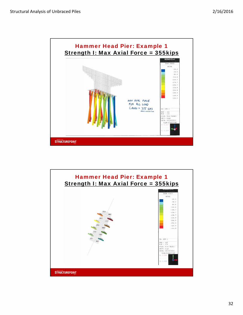
Hammer Head Pier: Example 1Controlling Load Case
• Strength Cases I – V were Checked
• Strength Case I controlled
• 1.25DC + 1.5DW + 1.75LL + 1.75BR
Structural Analysis of Unbraced Piles 2/16/2016
32
Hammer Head Pier: Example 1Strength I: Max Axial Force = 355kips
Hammer Head Pier: Example 1Strength I: Max Axial Force = 355kips

Structural Analysis of Unbraced Piles 2/16/2016
33
Hammer Head Pier: Example 1STR I: Max Strong-Axis Moment = 15.0ft-k
Hammer Head Pier: Example 1STR I: Max Strong-Axis Moment = 15.0ft-k

Structural Analysis of Unbraced Piles 2/16/2016
34
Hammer Head Pier: Example 1STR I: Max Weak-Axis Moment = 4.5ft-k
Hammer Head Pier: Example 1HP12x74 Section Properties
Area = 21.8 in2 Depth = 12.1 inWeb thick = 0.605 in Flange Width = 12.2 inFlange thick = 0.610 in
Ix = 569.0 in4 Iy = 186.0 in4
Sx = 93.8 in3 Sy = 30.4 in3
rx = 5.110 in ry = 2.920 inZx = 105.0 in3 Zy = 46.6 in3
rt = 3.260 inJ = 2.98 in4
Cw = 6170 in6

Structural Analysis of Unbraced Piles 2/16/2016
35
Hammer Head Pier: Example 1Calculate Slenderness Ratio
- Slenderness Ratio:/ 120 (Section 6.9.3)
0.85(28ft x 12in/ft) / 2.92in = 97.8
Hammer Head Pier: Example 1Calculate Pu / Pr
- Pu = 200.1 kips
- To Calculate Pr, Find Pe/Po
∗ (Eqn. 6.9.4.1.2-1)
.∗ 21.8 2 = 652.3k
Po = QFyAg
Po = 1.0(50ksi)(21.8in2) = 1090k
Pe/Po = 652.3k / 1090.0k = 0.60

Structural Analysis of Unbraced Piles 2/16/2016
36
Hammer Head Pier: Example 1Calculate Pu / Pr
Since Pe/Po > 0.44, then
0.658 ∗ (Eqn. 6.9.4.1.1-1)
0.658.
∗ 1090 541.6
Pr = Factored Compressive Resistance (Article 6.9.2.1)
Pr = c Pn = 0.9(541.6k) = 487.4k
Pu/Pr = (355.0k / 487.4) = 0.728
Since Pu/Pr > 0.2, Use Eqn. (6.9.2.2-2)
Hammer Head Pier: Example 1Combined Axial & Flexural Eqn.
Eqn. 6.9.2.2-18.0
9.01.0
Pu = 355.0k
Pr = 487.4k
Mux = 15.0 ft-k
Muy = 4.5 ft-k
Calculate Flexural Capacities Mrx & Mry

Structural Analysis of Unbraced Piles 2/16/2016
37
Hammer Head Pier: Example 1Calculate Strong-Axis Flexural Capacity
Calculate Flexural Resistance based on FLB & LTB
FLB
Calculate Section Ratios: f, pf and rf
f.
.10.0in
pf = 0.38 = 0.389.15in
rf = 0.95 = 0.95 . 19.9in
Hammer Head Pier: Example 1Calculate Strong-Axis Flexural Capacity
Calculate Flexural Resistance based on FLB & LTB
FLB
Since f > pf, then:
1 1f −
pfrf −
pf)]RpcMyc (Eqn. A6.3.2-2)
Rpc = 105in3/93.8in3 = 1.12Myc = 50ksi(93.8in3) = 4690 in-k
Fyr: taken as the smaller of: - 0.7Fyc = 35ksi
- ∗ = 50ksi
- Fyw = 50ksi- (But Not Less than 0.5Fyc)

Structural Analysis of Unbraced Piles 2/16/2016
38
Hammer Head Pier: Example 1Calculate Strong-Axis Flexural Capacity
Calculate Flexural Resistance based on FLB & LTB
FLB
1 1.
.
" −
"
" −
")](1.12x4690in-k)
5097.0in-k 424.8ft-k
Hammer Head Pier: Example 1Calculate Strong-Axis Flexural Capacity
Calculate Flexural Resistance based on FLB & LTB
LTBCalculate Plastic Length Limit (Lp) and Elastic Length Limit (Lr):
Section A6.3.3
28
1.0 (Eqn. A6.3.3-4)
1.0 3.26 78.5 6.5

Structural Analysis of Unbraced Piles 2/16/2016
39
Hammer Head Pier: Example 1Calculate Strong-Axis Flexural Capacity
Calculate Flexural Resistance based on FLB & LTB
LTBCalculate Plastic Length Limit (Lp) and Elastic Length Limit (Lr):
Section A6.3.3
1.95 1 1 6.76 ∗2
(Eqn. A6.3.3-5)
1.95 3.260.
. .1 1 6.76 ∗
. .
.
2
447.1 37.3ft
Hammer Head Pier: Example 1Calculate Strong-Axis Flexural Capacity
Calculate Flexural Resistance based on FLB & LTB
LTB
Since Lp < Lb < Lr,
1 1 (Eqn. A6.3.3-2)
1.0 1 135 93.8 3
1.12 469028 6.537.3 6.5
1.12 4690
3877.8 323.2

Structural Analysis of Unbraced Piles 2/16/2016
40
Hammer Head Pier: Example 1Calculate Strong-Axis Flexural Capacity
Calculate Flexural Resistance based on FLB & LTB
FLB5097.0in−k 424.8ft−k
LTB3877.8in−k 323.2ft−k
for LTB Controls
Mrx = fMnc = 0.9(323.2ft-k) = 290.0ft-k
Hammer Head Pier: Example 1Calculate Weak-Axis Flexural Capacity
Calculate Flexural Resistance based on FLB
FLB
Calculate Section Ratios: f, pf and rf
f.
.10.0in
pf = 0.38 = 0.389.15in
rf = 0.83 = 0.83 20.0in

Structural Analysis of Unbraced Piles 2/16/2016
41
Hammer Head Pier: Example 1Calculate Weak-Axis Flexural Capacity
Calculate Flexural Resistance based on FLB
FLB
Since f > pf, then:
1 1f pf
.(Eqn. 6.12.2.2.1-2)
1 1.
.
in in
.50 46.6 3
2266.5 188.9
Mry = fMn = 0.9(188.9ft-k) = 170.0ft-k
Hammer Head Pier: Example 1Combined Axial & Flexural Eqn.
Eqn. 6.9.2.2-28.09.0
1.0
Pu = 355.0k
Pr = 487.4k
Mux = 15.0 ft-k
Muy = 4.5 ft-k
Mrx = 290.0 ft-k
Mry = 170.0 ft-k
.
.
.
.
.
.
.
.0.798

Structural Analysis of Unbraced Piles 2/16/2016
42
Structural Analysis of Unbraced Piles
Example 2: Two Span Structure (100ft Ea)
Structural Analysis of Unbraced Piles
Plan View

Structural Analysis of Unbraced Piles 2/16/2016
43
Structural Analysis of Unbraced Piles
Plan View
Structural Analysis of Unbraced Piles
Cross-Section View

Structural Analysis of Unbraced Piles 2/16/2016
44
Single of Row Piles: Example 2
Single of Row Piles: Example 2

Structural Analysis of Unbraced Piles 2/16/2016
45
Single of Row Piles: Example 2
Single of Row Piles: Example 2Find Seismic Loads
• Calculate Seismic Forces
• Used Single Mode Spectral Method

Structural Analysis of Unbraced Piles 2/16/2016
46
Single of Row Piles: Example 2Find Seismic Loads
Single of Row Piles: Example 2Find Seismic Loads

Structural Analysis of Unbraced Piles 2/16/2016
47
Single of Row Piles: Example 2Find Seismic Loads
Single of Row Piles: Example 2Find Seismic Loads

Structural Analysis of Unbraced Piles 2/16/2016
48
Single of Row Piles: Example 2Find Seismic Loads
Single of Row Piles: Example 2Controlling Load Case
• Both Seismic Load Cases were checked
• Transverse Seismic Load Case controlled
• 1.25DC + 1.5DW + 0.3EQ + 1.0EQ

Structural Analysis of Unbraced Piles 2/16/2016
49
Single of Row Piles: Example 2(Max Axial Force = 200.1 kips)
Single of Row Piles: Example 2Strong Axis Moment = 5.6ft-k

Structural Analysis of Unbraced Piles 2/16/2016
50
Single of Row Piles: Example 2Weak Axis Moment = 33.8ft-k
Single of Row Piles: Example 2HP14x117 Section Properties
Area = 34.4 in2 Depth = 14.2 inWeb thick = 0.805 in Flange Width = 14.9 inFlange thick = 0.805 in
Ix = 1220.0 in4 Iy = 443.0 in4
Sx = 172.0 in3 Sy = 59.5 in3
rx = 5.960 in ry = 3.590 inZx = 194.0 in3 Zy = 91.4 in3
rt = 4.000 inJ = 8.02 in4
Cw = 19900 in6

Structural Analysis of Unbraced Piles 2/16/2016
51
Single of Row Piles: Example 2Calculate Slenderness Ratio
- Slenderness Ratio:/ 120 (Section 6.9.3)
1.2(17ft x 12in/ft) / 3.59in = 68.2
Single of Row Piles: Example 2Calculate Pu / Pr
- Pu = 200.1 kips
- To Calculate Pr, Find Pe/Po
∗ (Eqn. 6.9.4.1.2-1)
.∗ 34.4 2 = 2116.8k
Po = QFyAg
Po = 1.0(50ksi)(34.4in2) = 1720.0k
Pe/Po = 2118.8k / 1720.0k = 1.23

Structural Analysis of Unbraced Piles 2/16/2016
52
Single of Row Piles: Example 2Calculate Pu / Pr
Since Pe/Po > 0.44, then
0.658 ∗ (Eqn. 6.9.4.1.1-1)
0.658.
∗ 1720 1224.1
Pr = Factored Compressive Resistance (Article 6.9.2.1)
Pr = c Pn = 1.0(1224.1k) = 1224.1k
Pu/Pr = (200.1k / 1224.1k) = 0.163
Since Pu/Pr < 0.2, Use Eqn. (6.9.2.2-1)
Single of Row Piles: Example 2Combined Axial & Flexural Eqn.
Eqn. 6.9.2.2-1
21.0
Pu = 200.1k
Pr = 1224.1k
Mux = 5.6 ft-k
Muy = 33.8 ft-k
Calculate Flexural Capacities Mrx & Mry

Structural Analysis of Unbraced Piles 2/16/2016
53
Single of Row Piles: Example 2Calculate Strong-Axis Flexural Capacity
Calculate Flexural Resistance based on FLB & LTB
FLB
Calculate Section Ratios: f, pf and rf
f.
.9.25in
pf = 0.38 = 0.389.15in
rf = 0.95 = 0.95 . 19.9in
Single of Row Piles: Example 2Calculate Strong-Axis Flexural Capacity
Calculate Flexural Resistance based on FLB & LTB
FLB
Since f > pf, then:
1 1f −
pfrf −
pf)]RpcMyc (Eqn. A6.3.2-2)
Rpc = 194in3/172in3 = 1.13Myc = 50ksi(172in3) = 8600 in-k
Fyr: taken as the smaller of: - 0.7Fyc = 35ksi
- ∗ = 50ksi
- Fyw = 50ksi- (But Not Less than 0.5Fyc)

Structural Analysis of Unbraced Piles 2/16/2016
54
Single of Row Piles: Example 2Calculate Strong-Axis Flexural Capacity
Calculate Flexural Resistance based on FLB & LTB
FLB
1 1.
" − "
" −
")](1.13x8600in-k)
9683.6in-k 807.0ft-k
Single of Row Piles: Example 2Calculate Strong-Axis Flexural Capacity
Calculate Flexural Resistance based on FLB & LTB
LTBCalculate Plastic Length Limit (Lp) and Elastic Length Limit (Lr):
Section A6.3.3
17
1.0 (Eqn. A6.3.3-4)
1.0 4.000 96.3 8.0

Structural Analysis of Unbraced Piles 2/16/2016
55
Single of Row Piles: Example 2Calculate Strong-Axis Flexural Capacity
Calculate Flexural Resistance based on FLB & LTB
LTBCalculate Plastic Length Limit (Lp) and Elastic Length Limit (Lr):
Section A6.3.3
1.95 1 1 6.76 ∗2
(Eqn. A6.3.3-5)
1.95 4.000.
.1 1 6.76 ∗
.
.
2
597.0 49.8ft
Single of Row Piles: Example 2Calculate Strong-Axis Flexural Capacity
Calculate Flexural Resistance based on FLB & LTB
LTB
Since Lp < Lb < Lr,
1 1 (Eqn. A6.3.3-2)
1.0 1 135 172 3
1.13 860017 8.049.8 8.0
1.13 8600
8921.8 743.5

Structural Analysis of Unbraced Piles 2/16/2016
56
Single of Row Piles: Example 2Calculate Strong-Axis Flexural Capacity
Calculate Flexural Resistance based on FLB & LTB
FLB9683.6in−k 807.0ft−k
LTB8921.8in−k 743.5ft−k
for LTB Controls
Mrx = fMnc = 1.0(743.5ft-k) = 743.5ft-k
Single of Row Piles: Example 2Calculate Weak-Axis Flexural Capacity
Calculate Flexural Resistance based on FLB
FLB
Calculate Section Ratios: f, pf and rf
f.
.9.25in
pf = 0.38 = 0.389.15in
rf = 0.83 = 0.83 20.0in

Structural Analysis of Unbraced Piles 2/16/2016
57
Single of Row Piles: Example 2Calculate Weak-Axis Flexural Capacity
Calculate Flexural Resistance based on FLB
FLB
Since f > pf, then:
1 1f pf
.(Eqn. 6.12.2.2.1-2)
1 1.
.
in in
.50 91.4 3
4555.3 379.6
Mry = fMn = 1.0(379.6ft-k) = 379.6ft-k
Single of Row Piles: Example 2Combined Axial & Flexural Eqn.
Eqn. 6.9.2.2-1
21.0
Pu = 200.1k
Pr = 1224.1k
Mux = 5.6 ft-k
Muy = 33.8 ft-k
Mrx = 743.5 ft-k
Mry = 379.6 ft-k
.
.
.
.
.
.0.178

Structural Analysis of Unbraced Piles 2/16/2016
58
Structural Analysis of Unbraced Piles
QUESTIONS?