MASTER CIRCULAR Master Circular No. 62 Master Circular on ...
1
Why do appropriate non-circular chainrings yield
more crank power compared to conventional
circular systems during isokinetic pedaling?
L. Malfait, M.Mech.Eng.
G. Storme, M.Sc.Mech.Eng.
M. Derdeyn, M.Sc.Mech.Eng & Appl.Math.
January 2012.

2
Why do appropriate non-circular chainrings yield more crank power
compared to conventional circular systems during isokinetic pedaling?
L. Malfait, M.Mech.Eng., G. Storme, M.Sc.Mech.Eng.,
M. Derdeyn, M.Sc.Mech.Eng. & Appl.Math.
Abstract
Several studies have been published on the use of eccentric and non-circular
chainrings.
The findings of these studies have, however, not been consistent.
Despite the lack of consistent positive results in terms of physiological
responses, a consensus appears to prevail that the improved mechanical
effectiveness of the oval chainring may lead to performance enhancement (e.g.
increased crank power output) compared to the conventional circular
chainwheel.
Some authors assume non-circular chainrings may improve pedal dynamics by
reducing the effect of the "dead spot" in the pedaling cycle.
Other argue that an elliptical chainwheel should more efficiently match the
torque output capability of the rider to the torque input requirement of the
pedaling cycle.
Still other researchers conclude that non-circular chainrings can potentially
increase crank power relative to a conventional circular chainring by acting to
slowdown the crank angular velocity during the downstroke (power phase)
which allows muscles to generate power longer and to produce more external
work.
The pedal reaction force can be decomposed into a limb-static force and a limb-
dynamic force (gravity and inertial effects) component.
Static forces result from pedal forces only.
Dynamic forces and dynamic moments are needed to accelerate/decelerate (to
move) the lower limbs.
As a consequence crank power, joint-moments and joint-power are the result of
static pedal forces and of the dynamic forces/moments.
In a theoretical model, by assuming the static pedal forces being zero it
becomes possible to investigate the specific impact of the change of the
dynamic force component on the bicycle-rider system.
Altering the dynamic forces/moments is possible via ovality and shape of the
chainring, crank orientation angle, pedaling cadence, anthropometric values and
bike geometry.
The objective of this study was, relying on a torque-driven bicycle-rider
musculoskeletal model

3
first,
to study the dynamic joint-moments and dynamic joint-power as a function of
ovality and shape of the chainring, crank orientation angle and pedaling cadence
during isokinetic pedaling.
second,
to study the dynamic crank power output of non-circular chainrings when
applying the instantaneous dynamic joint-moments of the circular chainwheel on
the non-circular chainring.
In this case, per definition, the instantaneous dynamic crank power and average
dynamic crank power equal zero for the circular chainring. But the dynamic
average crank power of the non-circular chainring, when applying the dynamic
joint-loads of the circular chainring, will result in either an average crank power
gain or an average crank power loss compared to circular.
For each of the examined non-circular chainrings, the impact of crank
orientation angle and pedaling cadences are investigated.
As a general conclusion, the results of the study indicate that optimizing the
dynamic component of the joint-load by designing an appropriate non-
circular chainring (ovality, shape, crank orientation angle and cadence)
-gives rise to favourable differences in curve profiles and peak-values for both
the dynamic joint-moments and dynamic joint-powers compared to circular
-leads to a measurable crank power gain when applying the dynamic joint-
moments of the circular on the appropriate non-circular chainwheel.
This means that the dynamic joint-moments/forces needed to
accelerate/decelerate the limbs with a circular chainwheel are delivering the
dynamic joint-power needed to move the lower limbs with the appropriate
non-circular chainring and are yielding a crank power surplus.
1. Introduction
A considerable number of pedaling studies have been published on the use of
eccentric and non-circular chainrings (Henderson et al., 1977; Okajima, 1983;
Cullen et al., 1992; Hull et al., 1992; Barani et al., 1994; Hintzy et al., 2000; Hue
et al., 2001; Ratel et al., 2004; Martinez et al., 2006; Horvais et al., 2007; Hue et
al., 2007; A.D. Jones et al., 2008; Mateo et al., 2010 etc...).
The findings of these studies have, however, not been consistent.
This could be explained by the fact that only well trained cyclists, adapted to the
conventional round chainwheel, were recruited as subjects for this research.
Furthermore, it is difficult to set up good and reliable experimental designs to
carry out comparative studies since any cyclist is likely to be more efficient
when using the driving system he is accustomed to, whether circular or non-
circular.

4
In addition, all studies have been executed with crank orientation angles versus
major axis probably being not optimal (Malfait et al., 2010; Miller et al.,1980).
To validate by experiments the oval chainring's ability to improve performances
by analyzing biomechanical and/or physiological variables requires an adequate
(large and homogeneous) sample of trained cyclists and multiple (repeated)
measurements, being a very time consuming and consequently a very expensive
process. Indeed, differences may be small and sometimes not statistically
significant and consequently are not easy to record experimentally. Moreover,
the variability inherent in human performance tests may possibly obscure the
differences (Hull et al., 1992).
Nevertheless in a professional environment where all parameters are optimized,
small differences may determine the outcome of a competition.
Research with a mathematical model accurately describing the bike-rider system
and closely matching verification data definitely provides useful information
and is a powerful tool to support and even to be complementary to experimental
work. The use of a computational model is motivated by the fact that it is noise
free and therefore allows assessment of model tendencies that are too small to be
reliably picked up in an experiment (Hansen et al., 2009).
Despite the lack of consistent positive results in terms of physiological
responses (heart rate, oxygen consumption, blood lactate concentration, rating of
perceived exertion, carbon dioxide output etc..etc...) a consensus appears to
prevail that the improved mechanical effectiveness of the oval chainring may
lead to performance enhancement (e.g. increased crank power output) compared
to the conventional circular chainwheel.
Indeed, from a pure biomechanical perspective the use of elliptical chainrings
should provide theoretical benefits.
As an example, Rankin and Neptune (2008) identified a non-circular chainring
with ovality of 1.29 yielding an average crank power gain of 3.0% compared to
a conventional circular chainring at a pedaling rate of 90 rpm.
Some authors assume non-circular chainrings may improve pedal dynamics by
reducing the effect of the "dead spot" in the pedaling cycle and altering the
mechanical leverage. Time spent in positions of low mechanical advantage is
reduced, making the pedaling technique more efficient (i.e. Ferrari, 2004; Ratel
et al., 2004).
Also, an elliptical chainwheel should more efficiently match the torque output
capability of the rider to the torque input requirement of the pedaling cycle than
should a circular chainwheel (Henderson et al., 1977).
Other researchers argue that non-circular chainrings can potentially increase
crank power relative to a conventional circular chainring by acting to slowdown

5
the crank angular velocity during a part of the downstroke (power phase) which
allows muscles to generate power longer and to produce more external work
(Hintzy et al.,2000; Rankin et al., 2008).
Neither the "pedaling fast through the dead spot", the potential advantage of
"torque matching" nor the "slowdown during the downstroke" really explains
why non-circular chainrings could improve some aspects of the cycling
efficiency and performance (e.g. power output).
Several studies have analyzed the effects of non-circular chainrings compared to
conventional round chainwheels, but to the author's knowledge, no studies are
available answering even the most apparently obvious question:
why do (appropriate) non-circular chainrings yield more crank power compared
to conventional circular systems during isokinetic pedaling?
The primary goal of our research is to investigate why a non-circular chainring
has the ability to improve cycling performance by increasing average crank
power output during isokinetic cycling. But, directly related to this objective, the
examination of the dynamic forces/moments/power in the knee- and hip-joints is
necessary.
2. Methods
2.1. Basic Study
The "Comparative biomechanical study of circular and non-circular chainrings
for endurance cycling at constant speed. Release 2." (Malfait et al., 2010)
referred to as the "basic study", delivers more detailed information not necessary
reproduced in this paper.
2.2.Torque-driven bicycle-rider musculoskeletal model
The torque-driven musculoskeletal model of the "basic study", developed using
the MATLAB® software package, describes the bicycle-rider system.

6
Figure 1: Five bar linkage model of the bicycle-rider system
Model set-up (the bars, the links, the limbs, the joints, the pivot points, the
kinematic variables i.e. crank angle, the pedal forces and decomposition, the
joint forces and joint moments, the muscle groups involved, the anthropometric
parameters, the system geometry, etc...) is explained in the "basic study".
2.3. The dynamics of the pedaling process.
While in this study the term "dynamics" is being used, in many Anglo-Saxon
publications we read the term "kinetics".
The pedal reaction force can be decomposed into a limb-static force and a limb-
dynamic force (gravity and inertial effects) component.
As a consequence crank power, joint-moments and joint-power are the result of
static pedal forces and the dynamic forces/moments.
Dynamic forces and dynamic moments are needed to accelerate/decelerate (to
move) the lower limbs. This is explained in the chart below.
It is obvious that, assuming identical joint-loads, the crank power will be
changed by altering the dynamic components.

7
Altering the dynamic forces and the dynamic moments is possible via ovality
and shape of the chainring, crank orientation angle, pedaling cadence,
anthropometric values and bike geometry.
Figure 2: Schematic decomposition of pedal reaction force giving insight into
the dynamics of the pedaling process.
2.4. The free body diagram
To determine the kinetics of the model , free body diagrams of each link were
constructed.
The equations of motion were written.
From the free body diagram, the reaction forces in the joints and the joint
moments can be calculated for the ankle, the knee and finally for the hip.
The relations indicate the need to specify values of anthropometric parameters.
Additional input data were also necessary such as bike geometry, pedaling rate
etc...

8
Fhy
FhxX6,Y6
Xcgd,Ycgd
-mdg
X5,Y5
-Mk
-Fkx
-Fky
Mh
X5,Y5
Fky
Fkx
Mk
Xcgb,Ycgb
-mbg
X4,Y4-Fax
-Fay
-Ma
Fay
Fax
Ma
X4,Y4Xcgv,Ycgv
-mfg
Pfh
Pfv
X2,Y2
Hip
Thigh
Knee
Knee
Ankle
Ankle
Pedal axis
Shank
Foot
Figure 3: Free body diagrams of each link: balances of forces and moments.
Pfv = -Fy Fy = vertical force component exerted by the foot on the pedal
Pfh = -Fx Fx = horizontal force component exerted by the foot on the pedal

9
2.5. Basic relations for each link in the torque-driven model
From the free-body diagram (see figure 3) the reaction forces in the joints and
the joint moments can be calculated for the ankle, the knee and finally for the
hip.
For the foot with ankle joint:
Fax = mf * aXcgf – Pfh
Fay = mf * aYcgf – Pfv + mf * g
Ma = If * afootangle – Pfv * (X4 – X2) + Pfh * (Y4 – Y2)
– Fay * (X4 – Xcgf) + Fax * (Y4 - Ycgf)
Nomenclature:
Ma = ankle moment.
If = moment of inertia of the foot about its centre of gravity.
afootangle = angular acceleration of the foot.
Pfv = reaction force at the pedal, vertical component.
Pfh = reaction force at the pedal, horizontal component.
X2, Y2 = coordinates of pedal spindle.
X4, Y4 = coordinates of ankle axis.
Xcgf, Ycgf = coordinates of the centre of gravity of the foot.
Fax = force at the ankle joint, X component.
Fay = force at the ankle joint, Y component.
mf = mass of the foot.
aXcgf = linear acceleration of the centre of gravity of the foot, X component.
aYcgf = linear acceleration of the centre of gravity of the foot, Y component.
g = acceleration of gravity (9.81 m/s²)
Similar equations are defined for the shank with the knee joint (Fkx, Fky, Mk) and
for the thigh with the hip joint (Fhx, Fhy, Mh )
2.6 Values of anthropometric parameters and bike geometry.
Lengths, masses, moments of inertia and centre of gravity locations (CG) are
estimated using the work of Wells and Luttugens (1976). These parameters were
estimated for an average man who was 177.8 cm tall and weighed 72.5 kg.
Foot length: 0.161 m
Shank length: 0.436 m
Thigh length: 0.426 m
Moment of inertia foot about CG: 0.0023 kg.m²

10
Moment of inertia shank about CG: 0.0422 kg.m²
Moment of inertia thigh about CG: 0.0690 kg.m²
Mass foot: 0.98 kg
Mass shank: 3.04 kg
Mass thigh: 6.86 kg
Distance of CG foot to proximal joint: 0.069 m
Distance of CG shank to proximal joint: 0.189 m
Distance of CG thigh to proximal joint: 0.189 m
Bike geometry:
-crank arm length: 0.170 m
-seat tube angle: 73°
-saddle hight: 0.713 m (distance from crank spindle centre to hip joint)
2.7. Non-circular chainring types and definitions.
Definitions: 1. Crank angle
* crank arm vertical is the reference and equals 0°, position
arbitrary defined as being “Top-Dead-Centre” (T.D.C.)
*rotation: positive is counter clockwise
2. Crank orientation angle: the angle being measured from T.D.C
( = crank arm vertical), counter clockwise, to major axis of oval.
3. Optimal crank orientation angle: crank orientation angle
yielding highest average crank power, combined with the lowest
peak power load in the extensor joint muscles of knee and hip,
given the same joint moments for both, circular and non-circular
chainring at 90 rpm (see "basic study").
4. Ovality: ratio of major axis to minor axis length
Following chainrings are examined in this paper:
-Conventional circular chainring-ovality 1.00
"Circular"
-O.symetric original - crank orientation angle 78° - ovality 1.215
"Osy-Orig_78°"
-O.symetric optimal - crank orientation angle 110° - ovality 1.215
"Osy+4_110°"
-Q-Ring original - crank orientation angle 74° - ovality 1.10
"Q-Ring-Orig_74°"
-Q-Ring optimal - crank orientation angle 107° - ovality 1.10
"Q-Ring+4_107°"

11
-Ogival 140 original - crank orientation angle 75° (*) - ovality 1.428
"Ogival-140_73°"
-Ogival 140 optimal - crank orientation angle 107° - ovality 1.428
"Ogival-140_107°"
-Optimal - crank orientation angle 107° (**) - ovality 1.31
"Optimal_107°"
-Optimal+1 - crank orientation angle 114° - ovality 1.31
"Optimal+1_114°"
-Polchlopek original - crank orientation angle 102° - ovality 1.214
"Polchlopek-Orig_102°"
-Polchlopek optimal - crank orientation angle 109° - ovality 1.214
"Polchlopek+1_109°"
-OVUM 124 - crank orientation angle 106° - ovality 1.24
"OVUM 124+2_106°"
All chainrings considered in the study are 'normalised' in AutoCAD to 50 teeth.
Explanations and pictures about the non-circular chainrings can be reviewed in
the "basic study".
(*) differs from Ogival in "basic study" in terms of ovality and crank orientation
angle.
(**) named "LM-Super" in "basic study".
Isokinetic pedaling is defined as cycling at a constant pedaling rate e.g. 90
revolutions per minute, with both a circular chainring and a non-circular one.
During isokinetic pedaling with a circular chainring, the path of the foot is
circular and the crank angular velocity is constant.
During isokinetic pedaling with a non-circular chainring, the path of the foot is
circular and the crank angular velocity is varying through one revolution. The
phazing of the angular velocity variation and the amount of variation is
determined by the orientation of the crank arm along with the degree of
ovality.
The ovality of the non-circular chainring defines the maximum and the
minimum crank angular velocity. This means that oval chainrings with identical
ovality have identical maximum and minimum crank angular velocity.
The shape of the oval chainring defines the shape of the crank angular velocity
curve profile and by derivation the shape of the crank angular acceleration
curve and together with the crank angular velocity, the amplitude of the crank
angular acceleration.

12
Consequently, non-circular chainwheels with identical ovality but with
dissimilar shape have different angular acceleration curves. This gives the
opportunity for dynamic (kinetic) optimization.
By varying the crank arm orientation angle versus the major axis, the
phazing of the crank angular velocity and the crank angular acceleration curves
are changed throughout the pedaling cycle, which also gives an opportunity for
dynamic (kinetic) optimization.
Transformation formula for crank orientation angle:
Subtracting the above "scientific" defined crank orientation angle from 180°
gives a crank orientation angle measured from the major axis of the oval being
vertical with a positive angle in the direction of crank rotation when pedaling
forward.
As an example:
Q-Ring original - crank orientation angle 74° - can be easier "visualised" by
calculating 180° - 74° = 106°.
This means, having the major axis of the Q-Ring vertical, the crank arm is
oriented at 106°, clockwise, measured from vertical. This is also the notification
of the designer/manufacturer. This notification is more currently used.
Please notice that all the crank orientation angles mentioned in this study are
according to the "scientific" definition (see above).
2.8. Objective of the study
The objective of this paper was, relying on a torque-driven bicycle-rider
musculoskeletal model
first,
to study the dynamic joint-moments and dynamic joint-power as a function of
ovality, shape and crank orientation angle during isokinetic pedaling with
circular and non-circular chainrings at cadences of 40, 60, 80, 90, 100, 120 and
140 revolutions per minute (rpm).
second,
to study the dynamic crank power output of non-circular chainrings when
applying on the non-circular chainring the instantaneous dynamic joint-moments
of the circular chainwheel at cadences of 40, 60, 80, 90, 100, 120 and 140
revolutions per minute (rpm).
In this case, per definition, the instantaneous dynamic crank power and average
dynamic crank power equal zero for the circular chainring. The dynamic average
crank power of the non-circular chainring, when applying the dynamic

13
joint-loads of the circular chainring, will be either an average dynamic crank
power gain or an average dynamic crank power loss compared to circular.
For each of the non-circular chainrings the impact of the crank orientation angle
is investigated in two specific positions: the original crank orientation position
of the designer/manufacturer and the optimal position as defined in paragraph
2.7..
The analysis is based, purely on the laws of the theoretical mechanics.
The results are (bio-)mechanically correct. Physiological aspects are, primarily,
not taken into account because they are not part of the core-skills of the authors.
Although in an appendix, some physiological considerations will be made.
Minor errors or deviations may have a limited impact on the figures (assumed
anthropometric values, conversion of CAD drawings to crank angles,
polynomial conversion, assumed constant linear chain velocity throughout the
crank cycle, assumed pedal angle).
As mentioned above, in this analysis, only dynamic components are taken
into consideration. This is possible by equalling the pedal forces Pfv and Pfh to zero in the general
equations of forces and moments in the torque-driven model (see 2.5).
The only remaining forces/moments in the model are dynamic forces/moments
caused by gravity and inertial effects and are subject to examination.
14
3. Results dynamic joint-moments and dynamic joint-power.
3.1. Curve profile of dynamic joint-moments and dynamic joint-power.
Dynamic joint-moments (-torques) are the moments needed to be developed in
the joints, simply and solely to overcome the inertial (-mass) forces/moments
and the gravitational forces of the moving legs at different pedaling rates.
Per definition, dynamic joint-moments do not generate any crank power.
The same applies for the dynamic joint-power.
By means of an adapted Matlab® programme for each of the chainrings
considered, the curve profile of the dynamic joint-moments, respectively
dynamic joint-power were calculated as a function of cycle time and plotted,
given a specific pedaling cadence (rpm).
Each graph shows for the circular chainring and for a specific non-circular
chainwheel the evolution of the dynamic joint-moments/power versus cycle time
in the knee-joint and in the hip-joint.
"Data-tips" indicate the maximum values (peak-value).

15
3.2. Some examples of dynamic joint-moments curves.
Figure 4: Curve profile of dynamic knee and hip moment - 100 rpm
Circular chainring vs Osymetric-crank orientation angle 109.6°
- ovality 1.215

16
Figure 5: Curve profile of dynamic knee and hip moment - 90 rpm
Circular chainring vs Ogival 140-crank orientation angle 73°
- ovality 1.428
Notice the extremely erratic path of the Ogival curves.
17
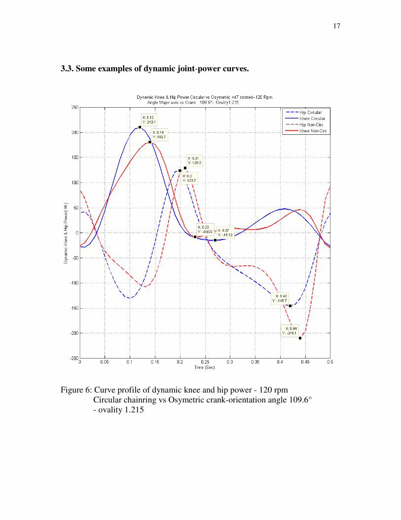
3.3. Some examples of dynamic joint-power curves.
Figure 6: Curve profile of dynamic knee and hip power - 120 rpm
Circular chainring vs Osymetric crank-orientation angle 109.6°
- ovality 1.215

18
Figure 7: Curve profile of dynamic knee and hip power - 120 rpm
Circular chainring vs Ogival 140 crank-orientation angle 73°
- ovality 1.428
Notice the extremely erratic path of the Ogival curves.

19
3.4 Relative importance of dynamic joint-moments/power
Dynamic joint moments/power are relatively important when being compared to
total joint moments/power assuming par example 104 W average crank power
per single-leg at 90 rpm (see "basic study").
This is explained in the next two graphs (fig 8 dynamic; fig 9 total)
Figure 8: Curve profile of dynamic knee and hip power - 90 rpm
Circular chainring vs Osymetric crank-orientation angle 109.6°
- ovality 1.215

20
Figure 9: Curve profile of total knee and hip power
Average crank power 104 W per single-leg at 90 rpm ("basic study")
Circular chainring vs Osymetric crank-orientation angle 109.6°
-ovality 1.215
For a circular chainring:
-total knee peak-power extensor muscles equals 237.3 W (hip 260.8 W)
-dynamic knee peak-power extensor muscles equals 94.25 W (hip 69.76 W)
being 39.7 % (hip 26.7 %) of total
For the Osymetric non-circular chainring - crank orientation angle 109.6°
-total knee peak-power extensor muscles equals 220.1 W (hip 263.6 W)
-dynamic knee peak-power extensor muscles equals 80.46 W (hip 68.67 W)
being 36.6 % (hip 26.1 %) of total
assuming 90 rpm and 104 W average crank power per single-leg.
21
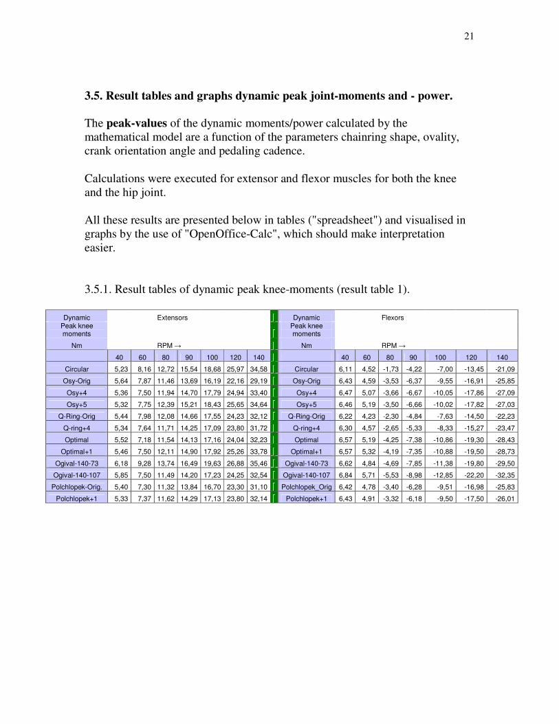
3.5. Result tables and graphs dynamic peak joint-moments and - power.
The peak-values of the dynamic moments/power calculated by the
mathematical model are a function of the parameters chainring shape, ovality,
crank orientation angle and pedaling cadence.
Calculations were executed for extensor and flexor muscles for both the knee
and the hip joint.
All these results are presented below in tables ("spreadsheet") and visualised in
graphs by the use of "OpenOffice-Calc", which should make interpretation
easier.
3.5.1. Result tables of dynamic peak knee-moments (result table 1).
Dynamic Extensors Dynamic Flexors
Peak knee moments
Peak knee moments
Nm RPM → Nm RPM →
40 60 80 90 100 120 140 40 60 80 90 100 120 140
Circular 5,23 8,16 12,72 15,54 18,68 25,97 34,58 Circular 6,11 4,52 -1,73 -4,22 -7,00 -13,45 -21,09
Osy-Orig 5,64 7,87 11,46 13,69 16,19 22,16 29,19 Osy-Orig 6,43 4,59 -3,53 -6,37 -9,55 -16,91 -25,85
Osy+4 5,36 7,50 11,94 14,70 17,79 24,94 33,40 Osy+4 6,47 5,07 -3,66 -6,67 -10,05 -17,86 -27,09
Osy+5 5,32 7,75 12,39 15,21 18,43 25,65 34,64 Osy+5 6,46 5,19 -3,50 -6,66 -10,02 -17,82 -27,03
Q-Ring-Orig 5,44 7,98 12,08 14,66 17,55 24,23 32,12 Q-Ring-Orig 6,22 4,23 -2,30 -4,84 -7,63 -14,50 -22,23
Q-ring+4 5,34 7,64 11,71 14,25 17,09 23,80 31,72 Q-ring+4 6,30 4,57 -2,65 -5,33 -8,33 -15,27 -23,47
Optimal 5,52 7,18 11,54 14,13 17,16 24,04 32,23 Optimal 6,57 5,19 -4,25 -7,38 -10,86 -19,30 -28,43
Optimal+1 5,46 7,50 12,11 14,90 17,92 25,26 33,78 Optimal+1 6,57 5,32 -4,19 -7,35 -10,88 -19,50 -28,73
Ogival-140-73 6,18 9,28 13,74 16,49 19,63 26,88 35,46 Ogival-140-73 6,62 4,84 -4,69 -7,85 -11,38 -19,80 -29,50
Ogival-140-107 5,85 7,50 11,49 14,20 17,23 24,25 32,54 Ogival-140-107 6,84 5,71 -5,53 -8,98 -12,85 -22,20 -32,35
Polchlopek-Orig. 5,40 7,30 11,32 13,84 16,70 23,30 31,10 Polchlopek_Orig 6,42 4,78 -3,40 -6,28 -9,51 -16,98 -25,83
Polchlopek+1 5,33 7,37 11,62 14,29 17,13 23,80 32,14 Polchlopek+1 6,43 4,91 -3,32 -6,18 -9,50 -17,50 -26,01

22
3.5.2. Result tables of dynamic peak hip-moments (result table 2).

23
3.5.3. Graphs dynamic peak knee/peak hip-moments of the extensor muscles.
Figure 10
40 60 80 100 120 140
0,00
5,00
10,00
15,00
20,00
25,00
30,00
35,00
40,00
Peak Dynamic Knee Moment - Extensors
Circular
Osy-Orig
Osy+4
Osy+5
Q-Ring-Orig
Q-ring+4
Optimal
Optimal+1
Ogival-140-73
Ogival-140-107
Polchlopek-Orig.
Polchlopek+1
Pedal Frequency RPM
Peak D
ynam
ic K
nee M
om
ent (N
m)
40,00 60 80 100 120 140
-40,00
-20,00
0,00
20,00
40,00
60,00
80,00
100,00
120,00
Peak Dynamic Hip Moment - Extensors
circular
Osy-Orig
Osy+4
Osy+5
Q-Ring-Orig
Q-Ring+4
Optimal
Optimal+1
Ogival-140-73
Ogival-140-107
Polchlopek-Orig
Polchlopek+1
Pedal Frequency RPM
Peak D
ynam
ic H
ip M
om
ent (N
m)

24
3.5.4. Graphs dynamic peak knee/peak hip-moments of the flexor muscles.
Figure 11
40 60 80 100 120 140
-35,00
-30,00
-25,00
-20,00
-15,00
-10,00
-5,00
0,00
5,00
10,00
Peak Dynamic Knee Moment - Flexors
Circular
Osy-Orig
Osy+4
Osy+5
Q-Ring-Orig
Q-ring+4
Optimal
Optimal+1
Ogival-140-73
Ogival-140-107
Polchlopek_Orig
Polchlopek+1
Pedal Frequency RPM
Peak D
ynam
ic K
nee M
om
ent (N
m)
40 60 80 100 120 140
-100,00
-90,00
-80,00
-70,00
-60,00
-50,00
-40,00
-30,00
-20,00
-10,00
0,00
Peak Dynamic Hip Moment - Flexors
circular
Osy-Orig
Osy+4
Osy+5
Q-Ring-Orig
Q-Ring+4
Optimal
Optimal+1
Ogival-140-73
Ogival-140-107
Polchlopek-Orig.
Polchlopek+1
Pedal Frequency RPM
Peak D
ynam
ic H
ip M
om
ent

25
3.5.5. Result tables of dynamic peak knee-power (result table 3).
3.5.6. Result tables of dynamic peak hip-power (result table 4).

26
3.5.7. Graphs dynamic peak knee/peak hip-power of the extensor muscles.
Figure 12
40,00 60 80 100 120 140
0,00
50,00
100,00
150,00
200,00
250,00
300,00
350,00
400,00
Dynamic Peak Power Knee-Extensors
Circular
Osy-Orig
Osy+4
Osy+5
Q-Ring-Orig
Q-ring+4
Optimal
Optimal+1
Ogival-140-73
Ogival-140-107
Polchlopek-Orig.
Polchlopek+1
Pedal Fraquency RPM
Dyn
am
ic P
eak Power (W
)
40,00 60 80 100 120 140
0,00
50,00
100,00
150,00
200,00
250,00
Dynamic Peak Power Hip Extensors
circular
Osy-Orig
Osy+4
Osy+5
Q-Ring-Orig
Q-Ring+4
Optimal
Optimal+1
Ogival-140-73
Ogival-140-107
Polchlopek-Orig.
Polchlopek+1
Pedal Frequency RPM
Dyn
am
ic P
eak P
ow
er

27
3.5.8. Graphs dynamic peak knee/peak hip-power of the flexor muscles.
Figure 13
40 60 80 100 120 140
-50
-45
-40
-35
-30
-25
-20
-15
-10
-5
0
Dynamic Peak Power Knee-Flexors
Circular
Osy-Orig
Osy+4
Osy+5
Q-Ring-Orig
Q-ring+4
Optimal
Optimal+1
Ogival-140-73
Ogival-140-107
Polchlopek-Orig.
Polchlopek+1
Pedal Frequency RPM
Dyn
am
ic P
eak P
ower (W
)
40 60 80 100 120 140
-450
-400
-350
-300
-250
-200
-150
-100
-50
0
Dynamic Peak Power Hip-Flexors
circular
Osy-Orig
Osy+4
Osy+5
Q-Ring-Orig
Q-Ring+4
Optimal
Optimal+1
Ogival-140-73
Ogival-140-107
Polchlopek-Orig.
Polchlopek+1
Pedal Frequency RPM
Dyn
am
ic P
eak P
ower (W
)

28
3.6. Comparison peak values dynamic moments/power of each non-circular
chainring versus the conventional circular one.
Differences were calculated between the peak values of the dynamic
moments/power of each non-circular chainwheel and the corresponding peak
values of the circular chainring, taken as the reference.
This approach makes the analysis much easier and may help to come to
conclusions.
3.6.1. Difference tables of dynamic peak knee-moments (result table 5).

29
3.6.2. Difference tables of dynamic peak hip-moments (result table 6).

30
3.6.3. Graphs differences dynamic peak knee/peak hip-moments of the extensor
muscles. Figure 14
40 60 80 100 120 140
-6
-5
-4
-3
-2
-1
0
1
2
Peak Dynamic Knee Moment - Extensors
Difference versus Circular
Circular
Osy-Orig
Osy+4
Osy+5
Q-Ring-Orig
Q-ring+4
Optimal
Optimal+1
Ogival-140-73
Ogival-140-107
Polchlopek-Orig.
Polchlopek+1
Pedal Frequency RPM
Peak Dyn
amic Knee M
oment (N
m) Difference vs C
irc.
40 60 80 100 120 140
-10
0
10
20
30
40
50
Peak Dynamic Hip Moment - Extensors
Difference versus Circular
circular
Osy-Orig
Osy+4
Osy+5
Q-Ring-Orig
Q-Ring+4
Optimal
Optimal+1
Ogival-140-73
Ogival-140-107
Polchlopek-Orig.
Polchlopek+1
Pedal Frequency RPM.
Peak D
yn H
ip M
om
. (N
m);--Diff. vs C
ircular

31
3.6.4. Graphs differences dynamic peak knee/peak hip-moments of the flexor
muscles. Figure 15
40 60 80 100 120 140
-2
0
2
4
6
8
10
12
Peak Dynamic knee Moment - Flexors
Difference versus Circular
Circular
Osy-Orig
Osy+4
Osy+5
Q-Ring-Orig
Q-ring+4
Optimal
Optimal+1
Ogival-140-73
Ogival-140-107
Polchlopek-Orig.
Polchlopek+1
Pedal Frequency RPM
Peak D
yn. Knee M
om
. (N
m) diff. vs. Circ.
40 60 80 100 120 140
-5
0
5
10
15
20
25
Peak Dynamic Hip Moment - Flexors
Difference versus Circular
circular
Osy-Orig
Osy+4
Osy+5
Q-Ring-Orig
Q-Ring+4
Optimal
Optimal+1
Ogival-140-73
Ogival-140-107
Polchlopek-Orig.
Polchlopek+1
Pedal Frequency RPM
Peak D
ynam
ic H
ip M
om
. (N
m) Diff. vs. Circ.

32
3.6.5. Difference tables of dynamic peak knee-power (result table 7).
3.6.6. Difference tables of dynamic peak hip-power (result table 8).

33
3.6.7. Graphs differences dynamic peak knee/peak hip-power of the extensor
muscles. Figure 16
40 60 80 100 120 140
-120
-100
-80
-60
-40
-20
0
20
40
Dynamic Peak Power Knee Extensors
Difference versus Circular
Circular
Osy-Orig
Osy+4
Osy+5
Q-Ring-Orig
Q-ring+4
Optimal
Optimal+1
Ogival-140-73
Ogival-140-107
Polchlopek-Orig
Polchlopek+1
Pedal Frequency
Dynamic Peak Pow. (W
) Diff. vs. Circ.
40 60 80 100 120 140
-40
-20
0
20
40
60
80
100
120
Dynamic Peak Power Hip Extensors
Difference versus Circular
Circular
Osy-Orig
Osy+4
Osy+5
Q-Ring-Orig
Q-ring+4
Optimal
Optimal+1
Ogival-140-73
Ogival-140-107
Polchlopek-Orig
Polchlopek+1
Pedal Frequency RPM
Dyn
am
ic P
eak P
ow. (W
) Diff. vs. Circ.

34
3.6.8. Graphs differences dynamic peak knee/peak hip-power of the flexor
muscles. Figure 17
40 60 80 100 120 140
-35
-30
-25
-20
-15
-10
-5
0
5
10
15
Dynamic Peak Power Knee Flexors
Difference versus Circular
Circular
Osy-Orig
Osy+4
Osy+5
Q-Ring-Orig
Q-ring+4
Optimal
Optimal+1
Ogival-140-73
Ogival-140-107
Polchlopek-Orig
Polchlopek+1
Pedaling Frequence RPM
Dynamic Peak Pow Flexors (W) Diff. vs. Circ.
40 60 80 100 120 140
-50,00
0,00
50,00
100,00
150,00
200,00
250,00
Dynamic Peak Power Hip Flexors
Difference versus Circular
Circular
Osy-Orig
Osy+4
Osy+5
Q-Ring-Orig
Q-ring+4
Optimal
Optimal+1
Ogival-140-73
Ogival-140-107
Polchlopek-Orig
Polclopek+1
Pedal Frequency RPM
Dyn
amic Pek Pow (W) Diff. vs. Circ.

35
3.7. Discussion/observations dynamic joint-moments and dynamic joint-power.
3.7.1. Discussion/observations dynamic joint-moments.
The curve profile of the dynamic joint-moments throughout a full crank cycle
shows the magnitude and the location of the dynamic peak joint-moments
(figure 4; figure 5).
The values of the dynamic peak joint-moments are a function of the pedaling
frequency, the ovality and the shape of the chainring, the orientation of the
crank versus the major axis of the oval, the anthropometric parameters and the
bike geometry.
The pedaling frequency.
The absolute values of the dynamic peak-moments which are acting on the
joints increase more than linear with increasing pedaling rates.
This is the case for all the chainwheels under examination.
Notice that within the range of 40 to 140 rpm the dynamic peak-moments
affecting the knee-extensor muscles increase with a factor 6 and those working
on the knee-flexor muscles increase with about the same factor also.
The dynamic peak-moments affecting the extensor and flexor muscles of the
hip joint increase with about a factor 4 with increasing pedaling rate.
Figure 10 and figure 11. Result table 1 and result table 2.
Normally, when pedal forces are produced, negative joint moments caused by
the flexor muscles and positive moments on the extensors are measured.
However in this study, where no static pedal forces are acting but only dynamic
forces/moments are considered to move the lower limbs, we measure positive
dynamic peak knee-moments caused by the flexors up to about 70 rpm (figure
11) and negative values beyond.
Likewise the dynamic peak hip-moments caused by the extensor muscles are
negative up to about 75 rpm and positive beyond (figure 10).
How to interpret/explain these observations?
The static component equals zero. Only the inertial forces/-moments and the
gravity forces acting on the moving lower limbs (dynamic forces/-moments) are
taken into account.
At low pedaling frequencies, the accelerations and as a consequence the inertial
forces/-moments are relatively small so that the gravity forces are dominant.
When only considering the gravity forces we can examine what the knee- and
hip moment should be to keep the gravity force in balance. See figure 18.

36
Figure 18: "Moments to balance the gravity forces" (simplified diagram).
We conclude:
-to balance in the knee joint the gravity forces of the foot and the shank, a positive
moment has to be realised in the knee joint during the whole crank cycle.
-to balance in the hip joint the gravity forces of the foot, the shank and the thigh, a
negative moment has to be realised in the hip joint during the whole crank cycle.
Of course, this situation is only valid in case no inertial forces/-moments are occurring.
This theoretically happens at a pedaling rate equal to zero, in practical terms at low
pedaling frequencies.
Apparently the inertial forces/-moments are sufficiently small up to 70 or 75 rpm.
From 75 rpm and more the inertial forces/-moments dominate the gravity forces and the
situation changes. Indeed the gravity forces are independent from the pedaling rate.

37
This analysis also reveals that in the knee and in the hip, because of the gravity forces,
the flexors are more and the extensors are less loaded. This is independent of the kind of
chainring and independent of the pedaling rate.
3.7.2. Comparison dynamic peak joint-moments with non-circular chainrings versus
circular ones. See result tables 5 & 6 and figures 14 & 15.
Negative differences reveal that smaller peak-moments occur in the joints with the
considered non-circular chainwheel compared to the round chainring taken as a reference.
Consequently negative differences are favourable, positive differences are unfavourable.
The pedaling frequency.
From about 50 rpm on, all the non-circular chainwheels examined (except: Ogival 140-
73°) have smaller dynamic peak moments caused by the knee extensor muscles compared
to a circular chainring. This favourable difference increases with increasing pedaling rate.
The dynamic peak moments caused by the knee flexors, the hip extensors (from 60 rpm
on, except. Osy +4/5) and the hip flexors (except. Q-ring orig) are less favourable
compared to the traditional round chainwheel. Also in this case the (unfavourable)
difference increases with increasing pedaling cadence.
Crank orientation angle.
By changing the crank orientation angle towards the "optimal" angle, the dynamic
peak moment differences are also changing.
-for the extensor muscles (both knee and hip): mostly a favourable change of the
differences (except: unfavourable for the knee-extensors with Osy, Optimal, Polchlopek)
-for the knee-flexors: a small worsening compared to circular
-for the hip-flexors: differences versus round becoming more unfavourable too.
Ovality and shape.
Assume the crank oriented in "optimal" position.
We focus on the pedaling rate range of 80 rpm up to 140 rpm.
Ovality: Q-ring (10%), Osy and Polchlopek (21.5%), Optimal (31%) and Ogival 140
(42.8%).
The differences in dynamic peak joint-moments versus round:
-for the knee extensors: the favourable differences are quasi independent of the increasing
ovality (only a weak unfavourable effect).
-for the hip extensors: the unfavourable differences increase significantly with increasing
ovality.
-for the knee flexors: unfavourable differences increase with increasing ovality
-for the hip flexors: unfavourable differences increase substantially with increasing
ovality.

38
3.7.3. Discussion/observations dynamic joint-power.
The curve profile of the dynamic joint-power throughout a full crank cycle
shows the magnitude and the location of the dynamic peak joint-power (figure 6;
figure 7).
The values of the dynamic peak joint-power are a function of the pedaling frequency,
the ovality and the shape of the chainring, the orientation of the crank versus the major
axis of the oval, the anthropometric parameters and the bike geometry.
The pedaling frequency.
The absolute value of the dynamic peak-power which is acting on the joints
increases with increasing pedaling rates.
This is the case for all the chainwheels under examination.
Notice that within the range of 40 to 140 rpm the dynamic peak-power affecting the
knee-extensor muscles increases more than linear and this with a factor of more than 20.
The dynamic peak-power affecting the knee-flexors remains roughly unchanged (except:
Ogival 140-73°, Osy orig and Q-ring orig).
The impact of the pedaling cadence on the dynamic peak-power affecting the hip-
extensors is far more moderate (about a factor 7) compared to the knee-extensors.
The dynamic peak-power on the hip-flexors increases with a factor well over 10.
The largest dynamic peak-power is developed on both the knee-extensors and the hip-
flexors. Their absolute values are in the same order of magnitude, especially in the higher
pedaling rates.
Figure 12 and figure 13. Result table 3 and result table 4.
3.7.4. Comparison dynamic peak joint-power with non-circular chainrings versus
circular ones. See result tables 7 & 8 and figures 16 & 17.
Negative differences reveal that smaller peak-power occurs in the joints with the
considered non-circular chainwheel compared to the round chainring taken as a reference.
Consequently negative differences are favourable, positive differences are unfavourable.
Difference table of dynamic peak power in the knee, affecting the knee-extensors (result
table 7):
-all non-circular chainrings give lower dynamic peak power affecting the extensor
muscles of the knee joint compared to circular. These favourable differences increase
with increasing pedaling rate (except Ogival 140-73°, unfavourable and increasing
unfavourable difference).
-an optimal crank orientation angle decreases the advantage versus round with an
exception for Q-ring and Ogival. Unfavourable Ogival even overturns into most
favourable compared to all other chainwheels.
39
-with optimal crank orientation angle and e.g. in the pedaling range 80-100 rpm
we notice a favourable effect of an increasing ovality: Q-ring (10% ovality), Osy and
Polchlopek (21.5%), Optimal (31%) and Ogival-140 (42.8%).
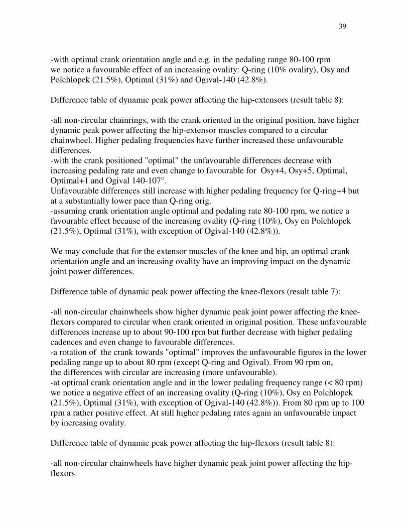
Difference table of dynamic peak power affecting the hip-extensors (result table 8):
-all non-circular chainrings, with the crank oriented in the original position, have higher
dynamic peak power affecting the hip-extensor muscles compared to a circular
chainwheel. Higher pedaling frequencies have further increased these unfavourable
differences.
-with the crank positioned "optimal" the unfavourable differences decrease with
increasing pedaling rate and even change to favourable for Osy+4, Osy+5, Optimal,
Optimal+1 and Ogival 140-107°.
Unfavourable differences still increase with higher pedaling frequency for Q-ring+4 but
at a substantially lower pace than Q-ring orig.
-assuming crank orientation angle optimal and pedaling rate 80-100 rpm, we notice a
favourable effect because of the increasing ovality (Q-ring (10%), Osy en Polchlopek
(21.5%), Optimal (31%), with exception of Ogival-140 (42.8%)).
We may conclude that for the extensor muscles of the knee and hip, an optimal crank
orientation angle and an increasing ovality have an improving impact on the dynamic
joint power differences.
Difference table of dynamic peak power affecting the knee-flexors (result table 7):
-all non-circular chainwheels show higher dynamic peak joint power affecting the knee-
flexors compared to circular when crank oriented in original position. These unfavourable
differences increase up to about 90-100 rpm but further decrease with higher pedaling
cadences and even change to favourable differences.
-a rotation of the crank towards "optimal" improves the unfavourable figures in the lower
pedaling range up to about 80 rpm (except Q-ring and Ogival). From 90 rpm on,
the differences with circular are increasing (more unfavourable).
-at optimal crank orientation angle and in the lower pedaling frequency range (< 80 rpm)
we notice a negative effect of an increasing ovality (Q-ring (10%), Osy en Polchlopek
(21.5%), Optimal (31%), with exception of Ogival-140 (42.8%)). From 80 rpm up to 100
rpm a rather positive effect. At still higher pedaling rates again an unfavourable impact
by increasing ovality.
Difference table of dynamic peak power affecting the hip-flexors (result table 8):
-all non-circular chainwheels have higher dynamic peak joint power affecting the hip-
flexors

40
compared to circular at original crank orientation angle (except: Q-ring). These
unfavourable differences increase over the complete pedaling frequency range with
exception for the Q-ring.
- a rotation of the crank towards "optimal" shows a substantial deterioration in these
already unfavourable figures.
-at optimal crank orientation and over the complete pedaling frequency range we notice
a distinct negative effect of increasing ovality.
We may conclude that, grosso modo, the optimal crank orientation angle and an
increasing ovality deteriorate further the unfavourable dynamic differences versus round
for the flexor muscles of the knee (to a lesser extent) and the hip (to a higher extent).
4. Results dynamic crank power.
When assuming that only dynamic moments are acting on the joints (to move
the legs), in this case the pedal forces are equal to zero at any time, as well as for
the conventional circular chainring as for any non-circular one.
As a consequence, no crank power is generated for both chainwheels: pedal
forces equal zero and the dynamic power is needed to move the lower limbs.
We learn from the examination of the dynamic joint-moments (see 3.) that the
curve of the dynamic joint-moments is a function of the ovality and the shape of
the non-circular chainwheel, the crank orientation angle and the pedaling
frequency.
When applying at any moment of the crank cycle, the instanteneous dynamic
joint-moments of the circular chainring on a specific non-circular chainring, we
will find either an average dynamic crank power gain or an average dynamic
crank power loss compared to circular ( = dynamic crank power difference).
By designing an appropriate ("good") non-circular chainring (ovality, shape,
crank orientation angle and cadence) the dynamic component of the joint-load
will be altered (optimized) compared to circular and leads to a measurable crank
power gain when applying the dynamic joint-moments of the circular on this
appropriate non-circular chainring.
Indeed, when applying the dynamic joint-moments of a circular on an
appropriate non-circular chainring,
1. the dynamic joint-power needed to move the lower limbs with the
appropriate non-circular is delivered and on top of this
2. a dynamic crank power is measured (is available) with the appropriate non-
circular chainwheel.
This examination was executed with the non-circular chainring types described

41
in paragraph 2.7. which gives the opportunity to see the impact of ovality, shape
and crank orientation angle on the dynamic crank power.
Pedaling cadences of 40, 60, 80, 90, 100, 120 and 140 revolutions per minute
are applied.
The results of this analysis should be considered in the design process of an
appropriate non-circular chainring.
4.1. Dynamic crank power difference non-circular chainring versus circular. Some examples.
Figure 19: Dynamic crank power difference at equal joint moments
Non-circular Optimal- ovality 1.31 - crank orientation angle 107° -
compared to circular chainring.
Pedal cadence 60 rpm.
Average dynamic crank power gain equals 0.4538 W per single-leg versus a
conventional round chainwheel.

42
Figure 20: Dynamic crank power difference at equal joint moments
Non-circular Optimal- ovality 1.31 - crank orientation angle 107°-
compared to circular chainring.
Pedal cadence 90 rpm.
Average dynamic crank power gain equals 3.301 W per single-leg versus
conventional round chainwheel.

43
4.2. Result table and graphs average dynamic crank power differences.
All the results are presented in a table ("spreadsheet") and illustrated in graphs
by the use of "OpenOffice-Calc", which should make interpretation easier.
For each of the studied oval chainwheels, average dynamic crank power
differences versus conventional round are presented for both, original and
optimal crank orientation angle and for the successive pedaling rates.
The model assumption of constant bicycle velocity (isokinetic pedaling)
effectively decouples the dynamics and kinematics of the two legs and allows
us to study the dynamic power differences of one isolated leg. Consequently
total dynamic crank power differences equals twice the single-leg figures (van den Bogert, A.J., 1994).
The dynamic crank power gain or loss is an absolute value expressed in Watt.
Gain or loss is independent from any pedal load performed.
This means that the relative dynamic crank power gain or loss is lower with
higher pedal load than with lower pedal load.
4.2.1. Result table average dynamic crank power differences vs circular.
Watt per single-leg. (result table 9)
Dynamic Crank Power
Difference trm
40 60 80 90 100 120 140
Circular 0 0 0 0 0 0 0
Osy-Orig_78° -0,0449 -0,0123 0,086 0,167 0,273 0,569 0,997
Osy+4_110° -0,1791 0,4458 1,928 3,080 4,553 8,607 14,380
Osy+5_117° -0,1966 0,4208 1,897 3,047 4,519 8,571 14,340
Q-Ring-Orig_74° 0,0150 -0,1050 -0,378 -0,588 -0,855 -1,587 -2,625
Q-ring+4_107° -0,0646 0,0448 0,324 0,546 0,831 1,620 2,750
Optimal_107° -0,2150 0,4538 2,054 3,301 4,897 9,292 15,550
Optimal+1_114° -0,2483 0,4577 2,160 3,488 5,190 9,881 16,560
Ogival-140_73° 0,1148 -0,2402 -1,090 -1,752 -2,600 -4,934 -8,258
Ogival-140_107° 0,2844 0,2859 1,711 2,834 4,28 8,267 13,97
Polchlopek-Orig 102° -0,1202 0,2514 1,1410 1,8340 2,722 5,166 8,646
Polchlopek+1_109° -0,2844 0,2869 1,3550 2,189 3,257 6,200 10,390
OVUM 124 +2_106° -0,1886 0,2484 1,323 2,166 3,248 6,235 10,500
A positive difference means an average dynamic crank power gain for the
non-circular chainring compared to the conventional round one.

44
4.2.2. Graphs average dynamic crank power differences vs circular.
Watt per single-leg. Figure 21
40 60 80 100 120 140
-10,0000
-5,0000
0,0000
5,0000
10,0000
15,0000
20,0000
f(x) = 0,05 x 3̂,25R² = 0,99
Difference Dynamic Crank Power
Circular vs Non-Circular
Circular
Osy-Orig_78°
Osy+4_110°
Osy+5_117°
Q-Ring-Orig_74°
Q-ring+4_107°
Optimal_107°
Optimal+1_114°
Machtregressie voor
Optimal+1_114°
Ogival-140_73°
Ogival-140_107°
Polchlopek-Orig 102°
Polchlopek+1_109°
Pedal Frequency RPM
Dyn
am
ic C
ran
k P
ow
er
diffe
rnce
( W
)
4.2.3. Result table average dynamic crank power differences vs circular.
Watt per double-leg.
It is obvious that the total (double leg) dynamic crank power difference or crank
power gain of a specific non-circular chainwheel versus the conventional
circular one can be calculated by doubling the figures of the single leg result
table 9.
4.3. Discussion/observations average dynamic crank power differences
versus circular. Result table 9. Figure 21.
The result tables and graphs indicate that, for a given non-circular chainring
(ovality and shape), the dynamic crank power difference versus the conventional
round chainring is a function of the pedaling frequency and the crank orientation
versus the major axis of the oval.

45
4.3.1 Impact pedaling frequency.
The average dynamic crank power difference compared to the circular
chainwheel (gain as well as loss) increases with increasing pedaling rate.
This increase/decrease with raising pedaling cadence is not linear but is a power
function of the form f(x) = A*x^n .
As an example for the oval Optimal +1, the function behaves like f(x) =
0.05*x^3.25 with x (grid number) as depiction of the pedaling frequency.
At lower pedaling rates (up to 60 rpm), the average dynamic crank power
gains/losses versus round are relatively small, even negligible. This is the case
for all the non-circular chainring combinations investigated.
At the normal pedaling cadences of competition cycling, the best performing
non-circular chainrings generate dynamic crank power gains of more than 4
Watt (at 80 rpm), up to even more than 10 Watt (at 100 rpm) "double leg".
At 110 rpm about 15 Watt crank power gain is available.
These results are also in line with the results published in the "basic study":
isokinetic pedaling at 90 rpm with 104 Watt crank power per single leg.
Indeed, in the "basic study", the crank power efficiency gain with the Osy+5
117° was 2.5% versus round (with identical joint moments on circular and on
non-circular).
The dynamic crank power gain of 3.047 Watt per leg at 90 rpm for the Osy+5
117° equates to 2.9% relative the 104 Watt per leg.
The dynamic advantage/disadvantage is an absolute value expressed in Watt.
Consequently the dynamic crank power gains/losses compared to the
conventional round chainwheel are independent from any external pedaling
load. This means that the relative dynamic crank power gain/loss is smaller with
higher pedal loading than with lower pedal loading.
Q-Ring 74° and Ogival_140_73° (both having original crank orientation angle)
yield negative dynamic crank power performances over the complete pedaling
frequency range 40-140 rpm. Even with an optimal crank orientation angle
the Q-ring performance remains (positively) weak.
Osy 78° (original) develops small positive dynamic crank power gains whereas
the Osy+4 110° and the Ogival 140 107° are ranking among the best ones.
Polchlopek+1 109° shows rather good figures comparable to OVUM+2 106°.
Optimal 107° and Optimal+1_114° are "best in class".

46
For all the non-circular chainrings under examination we can conclude that,
except for the combinations yielding negative values, an increasing pedaling
cadence has a positive impact on the dynamic crank power gain versus circular.
4.3.2. The apparent paradox regarding high pedaling rates. See appendix 4.6.1
4.3.3. Impact of ovality and shape.
Impact of ovality:
-assume: non-circular chainrings with crank orientation angle "optimal" versus
major axis
-ranking of the non-circular chainrings according to increasing ovality
We calculate the sum and the mean of the dynamic crank power gains in the
pedaling range 80-120 rpm. These pedaling cadences are typically used by
competition cyclists.
Result table 10
Ovality
%
Chainring
(crank orientation angle
optimal)
Sum and mean
dynamic crank
power gain vs. round
rpm 80 - 120
Watt (single-leg)
Comments
0.0 Round 0 0 Ellipse
10.0 Q-Ring 3.321 0.83 modified
ellipse
21.4 Polchlopek 13.001 3.25 bi-axis-symm
21.5 Osymetric 18.168 4.54 point symm
24.0 OVUM 12.972 3.24 Ellipse
31.0 Optimal 20.719 5.18 point symm
42.8 Ogival 17.092 4.27 bi-axis-symm
sum rpm 80-120 mean
The dynamic crank power gains compared to round (both the sum and the mean)
increase more than proportional to the ovality.
The chainwheels "round", "Q-ring" and "OVUM" are mathematical ellipses and
as a consequence perfectly comparable (no impact of shape differences). The
ovality of the OVUM increases with a factor 2.4 versus Q-ring whereas the
dynamic crank power gain increases with a factor 3.9.
The Optimal with similar shape compared to the Osymetric but with 9.5% more
ovality yields 14% more dynamic crank power gain versus Osy.

47
Impact of shape:
The Polchlopek oval has approximately the same dynamic crank power gains as
the OVUM but with 2.6% less ovality, most probably due to its specific shape.
Osymetric with quasi identical ovality as Polchlopek reveals about 40% more
dynamic crank power gain versus the last one. This can only be explained by its
specific point-symmetric shape.
Ogival, notwithstanding a very high ovality of 42.8%, develops lower dynamic
power gain compared to Optimal and Osymetric, without a doubt because of its
extreme shape which apparently works out adversely.
4.3.4. Impact of the crank orientation angle versus major axis.
For all the non-circular chainwheels under examination, the re-orientation
of the crank in the "optimal crank orientation angle position" i.e. in the range
110°-120° (see paragraph 2.7., definition 3. and also the "basic study") improves
substantially the dynamic crank power gains compared to the original crank
orientation angle of the designers/manufacturer.
We notice also the same "optimal crank orientation angle" in the publication
of Miller N.R. and Ross D. (1980) who developed a non-circular chainring
design (with crank at 120°, scientific definition) to maximize the average power
for one cycle produced by the pedaling movement.
The dynamic crank power losses of Q-Ring-orig_74° and Ogival-140_73°
are even transformed into dynamic crank power gains by re-orienting the crank
versus the major axis. The original Polclopek-102° has its crank quite close to
the optimal crank position.
It is remarkable that, for the pedaling frequency range of 40 rpm to 140 rpm,
a crank orientation angle of 73° (Ogival) and 74° (Q-ring) yields dynamic crank
power losses and that with 78° (Osymetric) only negligible dynamic crank
power gains are noticed.
A possible physiological explanation of this is given in appendix 4.6.2.
4.3.5. Consistency of results calculated by means of the bio-mechanical model
with experimentally measured results.
In scientific literature many publications are available reporting the results of
comparative laboratory and field testing of the conventional circular chainring
and non-circular ones.
These studies try to effectively measure the theoretical advantages of the
elliptical chainwheel in both sub and supra maximal cycling conditions.

48
As already noted above, these test results (mechanical, physiological and
muscular data) are for various reasons not always consistent.
Ratel et al. (2004) investigated the original Osymetric-Harmonic for
physiological parameters (13 test subjects) and were not able to identify
statistical significant benefits in sub and max test circumstances.
Horvais et al. (2007) studied the original Osymetric on physiological,
mechanical and muscular parameters, sub and supra maximal (12 test subjects).
The average crank power measured with the Wingate-test (predetermined fixed
moment/torque, pedaling rate to maximize) did not reveal any advantages for the
Osymetric.
Results of both studies are in contradiction with the unlikely (!) high power
gains in the "treshold zone" (6 up to 18% according to the criterion) as reported
in the publication of Barani et al. (1994) (19 test subjects).
Our torque-driven biomechanical model calculates negligible dynamic crank
power gains for the original Osymetric throughout the complete pedaling
frequency domain and is actually confirming (is consistent with) the findings of
Ratel and Horvais.
In late 2010, comparative tests between the Optimal oval and a conventional
round chainring were carried out (with 18 "well trained test subjects") in the
biomechanical laboratory of the department "Kinesiology" at the University of
Leuven, Belgium (Van Hoovels et al., 2010). Maximal crank power output was
measured during a series of short intermittent sprints on a isokinetic
(predetermined fixed pedaling rate, moment/torque to maximize) bicycle
ergometer. For all pedaling cadences between 40 rpm to 120 rpm (included) the
Optimal oval showed crank power gains compared to round. These
experimentally measured figures (e.g. 5.0 Watt at 80 rpm and 10.6 Watt at 100
rpm) confirm and even surpass slightly the dynamic crank power gains
calculated with the bio-mechanical model (e.g. 4.3 Watt at 80 rpm and 10.4
Watt at 100 rpm). The pedaling frequency range of 80 rpm till 100 rpm is
normally used by elite cyclists in competition. This study has not been published
yet.
In a preliminary report (8 test subjects) on Q-rings commercialized by Rotor Cy,
Martinez et al., (2006) analysed physiological and biomechanical effects.
Some physiological improvements were reported and also crank power gains
(+3 à 4%) compared to the conventional circular chainring. But the results were
not statistically analyzed and the improvements in terms of power output were
not clearly specified.
Jones et al., (2008) investigated with an excellent documented test protocol, in a
carefully controlled laboratory environment, randomized, single blind, in 2-
49
period cross-over trials (incremental tests to exhaustion with 12 test subjects)
physiological, mechanical and muscular parameters of the Q-ring, compared to a
circular chainwheel. Neither the mean crank peak-power output, nor the mean
crank power, nor the mean distance covered showed statistically significant
differences among the chainrings.
Mateo et al., (2010) compare in sprint tests (14 test subjects) the Q-ring to the
conventional round chainring. No statistically significant differences were
measured for the variables average speed and time to cover the sprint distance.
The above mentioned lab tests are completely in line with the figures calculated
with our bio-mechanical model, namely the absence of crank power gains with
the original Q-ring. This is most probably explained firstly by its lack of ovality
(the oval behaves like a circular ring) and secondly by the crank orientation
angle.
No experimental data are available for Ogival.
The original Polchlopek oval (crank orientation angle 102°) was advertised by
the designer/manufacturer as the non-circular yielding about 4% crank power
gain. It is not clear how this power gain has been measured.
Our bio-mechanical model calculates 3.6 Watt dynamic crank power gain at 90
rpm and 5.4 Watt at 100 rpm for the original Polchlopek. Assuming 200 to 250
Watt at 90 rpm for standard endurance cycling for experienced cyclists (Hull et
al., 1992) corresponds to about 2% dynamic crank power gain with the
Polchlopek chainring.
The Biopace-oval was tested by Hull et al., (1992). Not any advantage over
round was measured. In our "basic study", our bio-mechanical model did not
show any advantage over circular either. Obvious reasons are the very low
ovality (4%) and the totally wrong crank orientation angle (crank arm oriented
nearly parallel to the major axis). The Biopace was not studied in this paper, also
because Shimano withdrew the Biopace from market in 1992.
Koninckx et al., (2008) examined (22 well-trained cyclists) a novel pedal design
(Vista Pedal) and compared its power output and mechanical efficiency with the
conventional pedal. At 80 rpm a crank power gain of 2.5% (SD=0.6%) and at
100 rpm a crank power gain of 1.8% (SD=0.7%) is registered.
In our Project 002 (see website www.noncircularchainring.be), our torque-
driven biomechanical model calculates the crank power output and the joint
loading of the Vista Pedal and compares the results with the conventional pedal.
Our mathematical model shows a crank power gain of 2.7% at 90 rpm.
Thus the lab tests confirm (are matching) completely the results of the model.

50
Without doubt we may conclude that the figures generated by the torque-driven
bicycle-rider musculoskeletal model are consistent with the available
experimental results from designer/manufacturer independent experimental
research.
4.4. Internal work (-power), MMEE and total dynamic joint power.
In cycling research, internal work (internal power) is used to indicate the work
done (or the power developed) to move the cyclists legs through each crank
revolution (to accelerate and to decelerate the leg segments) and is defined as
"the sum of absolute changes in the total mechanical energy of the cyclists legs"
(Winter, D.A.,(1979); Welss, R., et al., (1986) and other...).
Muscular mechanical energy expenditure, MMEE, is defined as "the time
integral of the sum of the individual joint powers" (Aleshinsky, S.Y.,(1986),
Ingen Schenau et al., (1990) and other...)
Aleshinsky (1986) analysed mechanical energy expenditure and internal work
and concluded that mechanical energy expenditure does not equal to the sum of
internal and external work. Therefore, reduced internal work does not
necessarily correlate with reduced muscular mechanical energy expenditure.
Hull et al., (1992) tested the hypothesis (11 test subjects) that reducing internal
work would increase efficiency. They designed a crank angular velocity profile
(a non circular chainring) that reduced internal work by a minimum of 48%
relative to constant angular velocity cycling (circular chainring) over the range
of cadences generally preferred by endurance cyclists (80-100 rpm). The
experiment did not reveal advantages of the non-circular design over the
circular.
Kautz et al., (1994) also concluded that MMEE need not to be equal to the sum
of internal and external work and that reducing internal work in cycling does not
correlate with reduced MMEE.
Neptune et al., (1998) clearly demonstrated that internal work is not a valid
measure for the energy associated with moving the limbs and that the internal
work method is theoretically flawed and should not be used in cycling analysis.
Kautz et al., (2002) concluded that the internal work hypothesis is invalid as a
direct measure of the mechanical energy cost of moving the legs in pedaling.
Muscular mechanical energy expenditure is closely matching the definition of
total dynamic joint power. MMEE however is "energy" but conversion to
"power" is easily done. Moreover, MMEE includes pedal forces (external work)
whereas, per definition, in total dynamic joint power pedal forces are set to zero.
Only dynamic forces/moments caused by gravity and inertial effects are taken
into account.
51
Therefore "dynamic MMEE per unit of time" (i.e. pedal forces excluded) is
identical to "average (absolute values) total dynamic joint power".
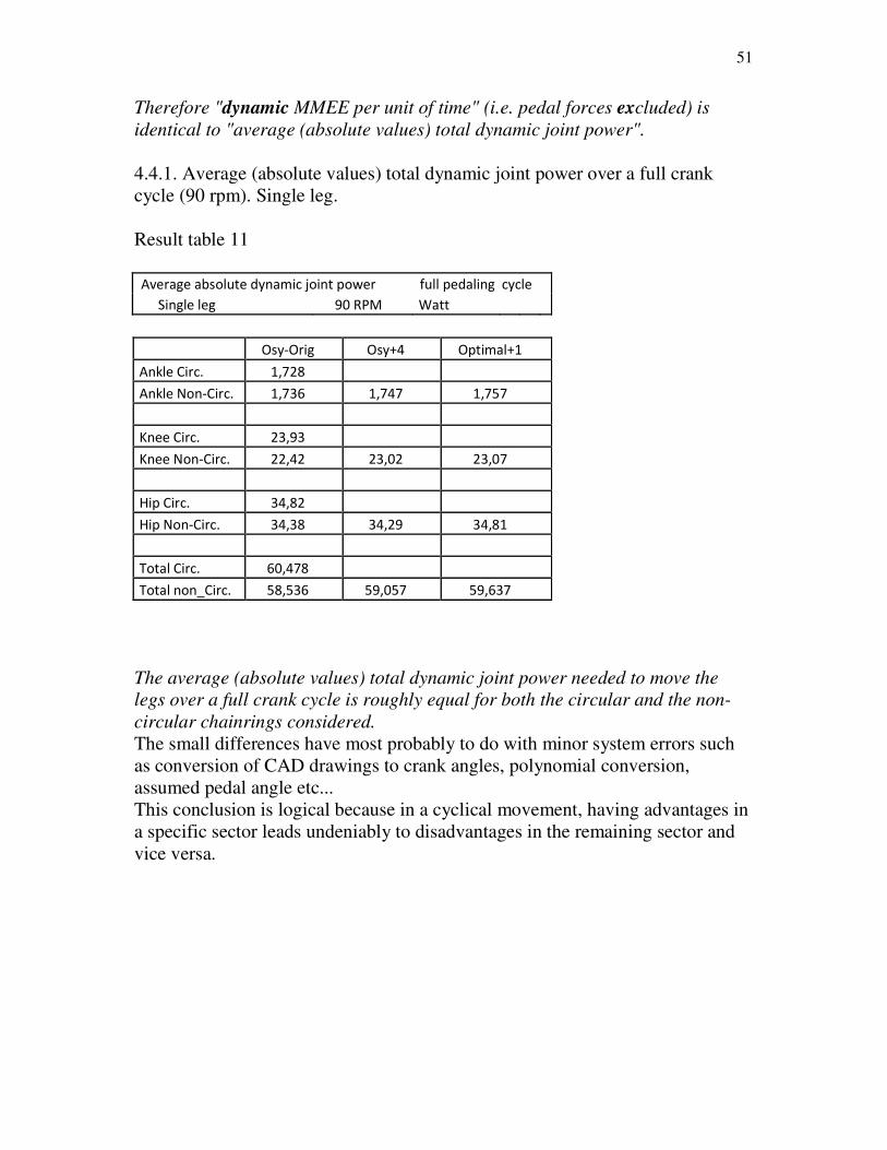
4.4.1. Average (absolute values) total dynamic joint power over a full crank
cycle (90 rpm). Single leg.
Result table 11
Average absolute dynamic joint power full pedaling cycle
Single leg 90 RPM Watt
Osy-Orig Osy+4 Optimal+1
Ankle Circ. 1,728
Ankle Non-Circ. 1,736 1,747 1,757
Knee Circ. 23,93
Knee Non-Circ. 22,42 23,02 23,07
Hip Circ. 34,82
Hip Non-Circ. 34,38 34,29 34,81
Total Circ. 60,478
Total non_Circ. 58,536 59,057 59,637
The average (absolute values) total dynamic joint power needed to move the
legs over a full crank cycle is roughly equal for both the circular and the non-
circular chainrings considered.
The small differences have most probably to do with minor system errors such
as conversion of CAD drawings to crank angles, polynomial conversion,
assumed pedal angle etc...
This conclusion is logical because in a cyclical movement, having advantages in
a specific sector leads undeniably to disadvantages in the remaining sector and
vice versa.
52
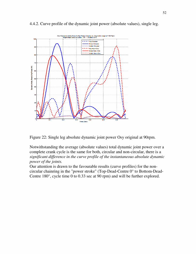
4.4.2. Curve profile of the dynamic joint power (absolute values), single leg.
Figure 22: Single leg absolute dynamic joint power Osy original at 90rpm.
Notwithstanding the average (absolute values) total dynamic joint power over a
complete crank cycle is the same for both, circular and non-circular, there is a
significant difference in the curve profile of the instantaneous absolute dynamic
power of the joints.
Our attention is drawn to the favourable results (curve profiles) for the non-
circular chainring in the "power stroke" (Top-Dead-Centre 0° to Bottom-Dead-
Centre 180°, cycle time 0 to 0.33 sec at 90 rpm) and will be further explored.
53
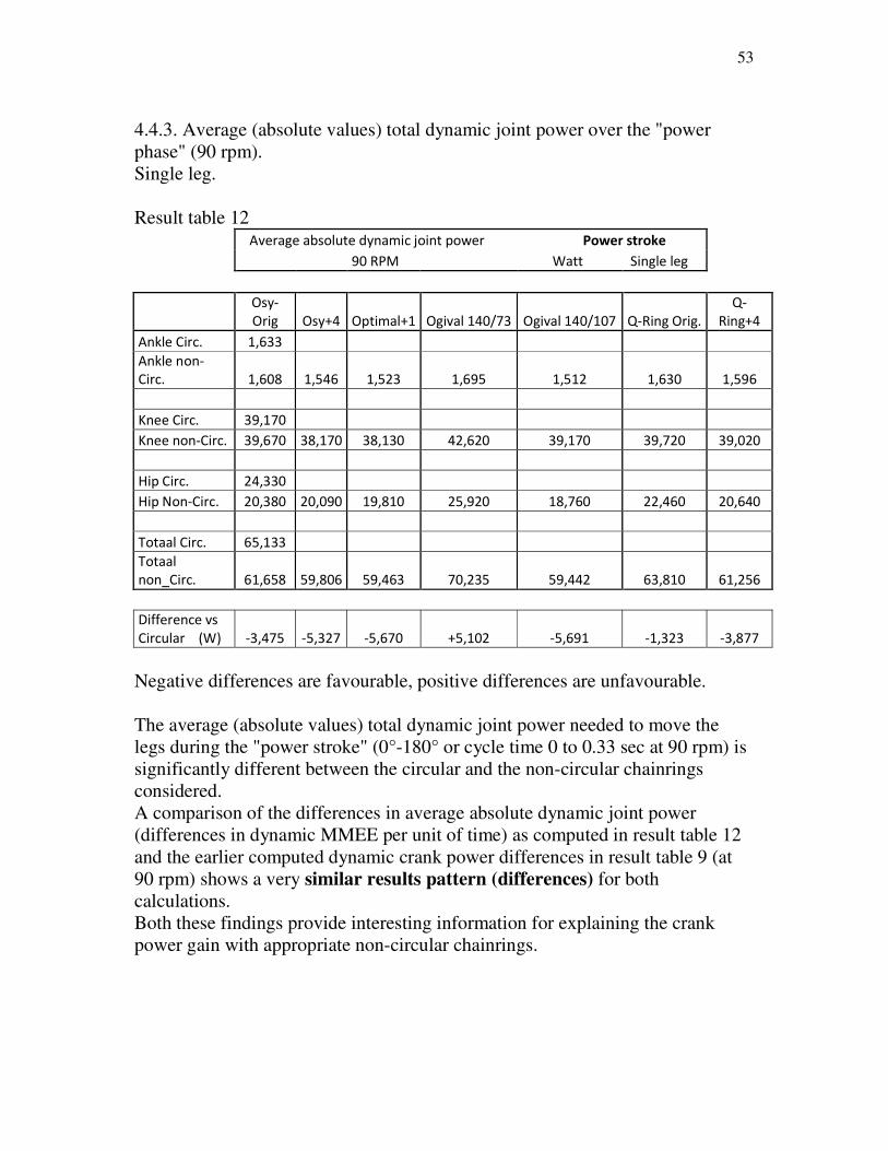
4.4.3. Average (absolute values) total dynamic joint power over the "power
phase" (90 rpm).
Single leg.
Result table 12 Average absolute dynamic joint power Power stroke
90 RPM Watt Single leg
Osy-
Orig Osy+4 Optimal+1 Ogival 140/73 Ogival 140/107 Q-Ring Orig.
Q-
Ring+4
Ankle Circ. 1,633
Ankle non-
Circ. 1,608 1,546 1,523 1,695 1,512 1,630 1,596
Knee Circ. 39,170
Knee non-Circ. 39,670 38,170 38,130 42,620 39,170 39,720 39,020
Hip Circ. 24,330
Hip Non-Circ. 20,380 20,090 19,810 25,920 18,760 22,460 20,640
Totaal Circ. 65,133
Totaal
non_Circ. 61,658 59,806 59,463 70,235 59,442 63,810 61,256
Difference vs
Circular (W) -3,475 -5,327 -5,670 +5,102 -5,691 -1,323 -3,877
Negative differences are favourable, positive differences are unfavourable.
The average (absolute values) total dynamic joint power needed to move the
legs during the "power stroke" (0°-180° or cycle time 0 to 0.33 sec at 90 rpm) is
significantly different between the circular and the non-circular chainrings
considered.
A comparison of the differences in average absolute dynamic joint power
(differences in dynamic MMEE per unit of time) as computed in result table 12
and the earlier computed dynamic crank power differences in result table 9 (at
90 rpm) shows a very similar results pattern (differences) for both
calculations.
Both these findings provide interesting information for explaining the crank
power gain with appropriate non-circular chainrings.

54
4.4.4. Dynamic crank power differences and average total absolute dynamic
joint power differences.
During the "power stroke" and assuming external loading, the extensor
muscles are predominantly recruited and provide most of the forward drive
(external crank power) for the bicycle movement.
If during the "power stroke" the average total absolute dynamic joint power is
lower with an appropriate non-circular chainwheel than with a circular one,
there is a possibility for the extensors to generate more external crank power
compared to circular. Any "unloading" of the extensors by an objectively
demonstrable (measurable) dynamic advantage may only be favourable
regarding extensor muscle fatigue and performance. Maximum performance is related to fatigue of lower limb muscles (Hull and
Gonzales, 1988).
Muscle fatigue is related to muscle stress to a power between 1.5 to 5
(Crowninshield and Brand, 1981). In pedaling activity the lower limb muscle
stress may be determined with good accuracy directly from the joint moments
developed by hip, knee and ankle (Redfield and Hull, 1986b).
Minimizing the stress would lead to reduced fatigue and hence improved
performance (Hull and Gonzales, 1988). This is most probably the case when
cycling with appropriate chainrings (lower dynamic joint moments and lower
dynamic joint powers) during the "power stroke".
As noted above, the average (absolute values) total dynamic joint power needed
to move the legs over a full crank cycle is roughly the same for both the circular
and the non-circular chainrings considered.
Having the average (absolute values) total dynamic joint power lower in the
"power stroke" for appropriate non-circular chainrings, leads inevitably to
higher total dynamic joint power during the "upstroke" (recovery phase, BDC
180° to TDC 360°), compared to circular.
Consequently during the "upstroke", the flexor muscles (not so much loaded
indeed) are charged more compared to circular but nearly no external crank
power must /may be provided in that sector.
When applying at any moment of the crank cycle, the instantaneous dynamic
joint-moments of the circular chainring on an appropriate non-circular chainring,
we find an average dynamic crank power gain (see earlier i.e. 4.2.1.)
As an example taking the Optimal+1 114°, at 90 rpm, 3.488 Watt (single leg)
dynamic crank power gain versus round has been computed (full crank cycle).
The favourable difference versus circular in average (absolute values) total
dynamic joint power at 90 rpm over the "power stroke" is 5.670 Watt (single
leg) for the non-circular, giving the possibility to the extensor muscles to
generate crank power with the instantaneous dynamic joint-moments of the

55
circular. However, this "unloading" of the extensors in the "power stroke" is
partly lost by an "overloading" of the flexors in the "upstroke" resulting in the
mentioned average dynamic crank power gain over the full crank cycle.
Same observations are valid for all the non-circular chainrings studied.
The "overloading loss" in the "upstroke" counts for about (single leg) 2 to 3
Watt (rounded) at 90 rpm, depending on the oval considered.
4.5. Concluding remarks
The results of the study undeniable suggest that an optimization of the dynamic
component of the joint loading in cycling, by the design of an appropriate non-
circular chainring, provides objectively demonstrable advantages to the non-
circular chainring compared to the conventional circular one. "Objectively
demonstrable" means: correctly computable according to the physical laws of
the kinematics and dynamics (kinetics).
The optimization of the dynamic component of the joint loading is obtained by a
good choice of the geometric parameters of the non-circular chainwheel namely
a sufficiently large ovality, the right shape and the "optimal" crank angle
orientation versus the major axis.
An important conclusion is that with an appropriate non-circular chainring the
dynamic peak joint moment and the dynamic peak joint power in the knee
extensor muscles are lower than with the circular chainring and that the
advantages increase with increasing pedaling rate.
For the knee joints, experience shows that the extensor muscles are an important
restricting factor. Overloading the knee extensor muscles frequently leads to
knee injuries. The appropriate non-circular chainring may provide a lower
potential for knee injuries.
The peak values on the knee flexor and the hip extensor/flexor muscles are not
systematically lower or higher compared to the conventional circular chainwheel
but each specific individual combination has to be examined.
We also learn that dynamic joint moments/-power are relatively important when
being compared to the total joint moments/power developed during standard
endurance cycling for experienced/competition cyclists.
Another important conclusion is that the appropriate non-circular chainring
yields a measurable average crank power gain compared to circular. This
dynamic crank power gain, generated by favourable kinematic/dynamic effects
on the moving masses of the lower limbs is rather modest but increases
"exponentially" with increasing pedaling frequency and is independent from any
56
external pedaling load. Consequently this crank power gain is becoming
relatively smaller with higher external pedal load.
The dynamic crank power gains of appropriate non-circular chainrings are
computable by means of adequate bio-mechanical musculoskeletal models but
are also measurable with lab experiments. This however is dependent on
condition of a good "design of experiment", a sufficiently large and
homogeneous test sample and multiple measurements. These conditions are not
always met in literature.
Osymetric is the best performing commercially available oval chainring,
followed by Ogival but for both only if the crank arm is oriented in the optimal
position. However the largest crank power gain versus circular is reached by the
Optimal (LM-Super) chainring.
Summarizing the line of thought:
-In the study, an objective difference is shown in the curving and the peak values
of the dynamic (kinetic) joint moments and dynamic (kinetic) joint powers
throughout the pedaling cycle for circular and non-circular chainwheels. It is
proven that this objective difference is a function of ovality, shape and crank
orientation angle. Also the impact of the pedaling rate is demonstrated.
-From this, it is already possible to distinguish good from less good geometric
combinations but this can not be quantified in terms of dynamic (kinetic) crank
power gain or loss.
-To make it quantifiable the method of equalization of the joint moments
(circular versus non-circular) is developed. The rationale behind this is: in case
the joint moments are identical, the lower limb muscle stress is equal too and
leads to the same muscle fatigue.
-When working out this hypothesis, a quantified dynamic (kinetic) crank power
gain/loss is shown for the different combinations of chainring geometry and
pedaling rate. A ranking of the non-circular chainrings is possible.
Notice that, keeping the joint moments identical, the joint angular velocities are
different. Possible physiological effects of this are not taken into account in the
model.
4.6. Appendix
As mentioned before, physiological aspects are, in first order, not taken into
account in this paper because they are not the field of speciality of the authors.
"Outside the paper", this appendix is an attempt to explain two remarkable
findings, by means of physiological considerations.

57
4.6.1. The apparent paradox regarding high pedaling rates.
As appears from the graphs, dynamic joint moments and dynamic joint powers
increase "more than linear" with increasing pedaling rate, although not so
strongly as the dynamic crank power gain.
Besides, the increase of the dynamic joint moments/-powers with the
"appropriate ovals" is far less distinct compared to the circular chainwheel.
This suggest that the "internal power" (which is in fact a "dynamic loss", the
power needed to move the lower limbs without producing any crank power)
increases "more than linear" with higher pedaling rates.
At first glance we may conclude that cycling at high pedaling frequency yields
no advantage. Nevertheless a.o. the best Time Trial performances are put up at
higher pedaling cadences (e.g. 100 rpm and more).
This has most probably to do with consequences (aspects) of the "force-
velocity" relationship of working skeletal muscles and the deduced relationship
"power-velocity". See figure 23 below.
Probably at the higher pedaling rates the cyclist is still on the ascending limb of
the muscle power curve resulting from the force-velocity relationship because
optimal power output occurs at much higher pedaling frequency (120 rpm),(van
Soest et al., 2000).
This would mean that, notwithstanding a higher internal power (higher
"dynamic loss") it still remains possible to develop even more muscle power.
Figure 23: Force-velocity-power-efficiency relationship for skeletal muscle

58
Since for the same pedaling rate, with appropriate ovals, the maximal and
average contraction (shortening) speed of the extensor muscles is lower than
with a circular chainring, it is expected that with these ovals a higher pedaling
rate can be reached and can (would) be advised.
This assumes (is on condition) that the indeed less loaded flexors are able "to
follow".
4.6.2. A conceivable explanation for the "optimal crank orientation angle".
It is remarkable that, over the pedaling frequency range 40 rpm up to 140 rpm,
a crank angle versus major axis of 73° (Ogival) and 74° (Q-ring) generates
increasing dynamic crank power losses and that with 78° (Osymetric) only
negligible crank power gains are recorded.
One possible explanation for this is that, with increasing pedaling rates,
the muscle coordination (electromyografical onset and offset) is altered.
Thus the crank angles corresponding to muscle force response (the delay
between the neural excitation arriving at the muscle and the muscle developing
force) increase significantly with pedaling cadence.
Consequently the force production of lower limb extensor muscles is shifted
later in the crank cycle. Hence, force is produced on pedals during less effective
crank cycle sectors of the "power stroke" and even during the beginning of the
"upstroke" (Samozino et al., 2007).
With crank orientation angles of 73°, 74° and 78° and putting the major axis of
the oval vertical, the crank arm is relatively low positioned in the down stroke
and is already located close to or in the less effective sectors of the pedaling
cycle. This also means that the above mentioned non-circulars have their largest
gears close to these less effective pedaling sectors. At increasing and higher
pedaling rates these ineffective positions become more distinctive.
Consequently, the larger gears are less efficiently exploited which is reflected in
the weaker performances.
Most probably the conclusions of Samozino et al., are a logical explanation why,
when looking for an "optimal crank orientation angle", having the major axis of
the oval chainring vertical, the crank arm must be positioned rather high in the
pedaling cycle.

59
Overview of the studied non-circular chainrings
O.symetric-Harmonic
Q-Ring (Rotor)
Polchlopek oval
Ovum
Ogival
LM-Super

60
Acknowledgements
The authors are grateful to Wendy Purshouse M.A.Eng.Lit. for her
constructive comments on the manuscript and to Gaby Demeester,
M.Sc.Mech.Eng., Lawyer and Patent Attorney for his advice on how to
protect the content of this paper.
References
1. ALESHINSKY, S.Y, An energy 'sources' and 'fractions' approach tot the mechanical energy
expenditure problem-I. Basic concepts description of the model, analysis of a one-link system
movement; II Movement of the multi-link chain model. J. Biomechanics 19, 287-293,
1986a/1986b.
2. BARANI, D., COMMANDRE, F., and DIGION, A., The ‘Harmonic Chainring’: presentation
and biomechanical characteristics. Med Sport 68: 77-81, 1994.
3. BOLOURCHI, F., and HULL, M.L., Measurement of rider induced loads during simulated
bicycling. Int. J. Sport Biomechanics 1, 308-329, 1985.
4. BURKE, R., High Tech Cycling. Human Kinetics, 1996.
5. CROWNINSHIELD, R.D. and BRAND, R.A., A physiological based criterion of muscle
force predictionin locomotion. J.Biomechanics 14, 793-801, 1981
6. CULLEN, L., ANDREW, K., LAIR, K., WIDGER, M., and TIMSON, B., Efficiency of
trained cyclists using circular and noncircular chain rings. Int. J. Sports Med; 13(3): 264-
269, 1992.
7. DAPENA, J., A method to determine the angular momentum of a human body about three
othogonal axes passing through its center of gravity. Journal of Biomechanics 11, 251-
256,1978.
8. DEMPSTER, W. T., and GANGRAN, R.L., Properties of body segments based on seize and
weight. American Journal of Anatomy, 120, 33-54, 1967.
9. FERRARI, M., Pedal stroke efficiency. 53X12.com 5/7/2004 Accessed 31/7/2007
10. HANSEN, E.A., JENSEN, K., HALLEN, J., RASMUSSEN, J., and PEDERSEN, P.P., Effect
of chain wheel shape on crank torque, freely chosen pedal rate, and physiological responses
during submaximal cycling. Journal of Physiological Anthropology 28(6):261-267, 2009
11. HANSEN, E.A., JORGENSEN, L.V., SJOGAARD, G., A physiological counterpoint to
mechanistic estimates of "internal power" during cycling at different pedal rates. Eur J Appl
Physiol 91:435-42. 2004
12. HENDERSON, S.C., ELLIS, R.W., KLIMOVITCH, G., and BROOKS, G.A., The effects of
circular and elliptical chainwheels on steady-state cycle ergometer work efficiency. Medicin
and Science in Sports and Exercise 9, 202-207, 1977.
13. HINTZY, F., BELLI, A., ROUILLON, J.-D., and GRAPPE, F., Effects of non-circular
chainwheel on force-velocity relationship during sprinting on a cycle ergometer. Science
et motricité 40, 42-47, 2000.
14. HORVAIS, N., SAMOZINO, P., ZAMEZIATI, K., HAUTIER, C., HINTZY, F., Effects of a
non-circular chainring on muscular, mechanical and physiological parameters during cycle
ergometer tests Isokinetics and Exercise Science 15, Number 4, 2007.
15. HUE, O., GALY, O., HERTOGH, C., CASTIES, and J., PREFAUT, C., Enhancing cycling
performance using an eccentric chain ring. Med Sci Sports Exerc 33(6), 1006-1010, 2001.

61
16. HUE O., CHAMARI, K., DAMIANI, M., BLONC, S., and HERTOGH, C., The use of an
eccentric chainring during an outdoor 1 km all-out cycling test. J Sci Med Sport 10(3),180-6,
2007.
17. HULL, M.L.and JORGE, M., A method for biomechanical analysis of bicycle pedalling.
J. Biomechanics 18: 631-644, 1985.
18. HULL, M.L., GONZALES, H. and REDFIELD, R., Optimization of pedaling rate in cycling
using a muscle stress-based objective function. Int. J. Sport Biomechanics 4, 1-21,1988.
19. HULL, M.L., KAUTZ, S.A., and BEARD, A., An angular velocity profile in cycling derived f
rom mechanical energy analysis. J. Bio mech. 24:577-586, 1991.
20. HULL, M.L., WILLIAMS, M., WILLIAMS, K., and KAUTZ, S.A., Physiological response to
cycling with both circular and non-circular chainrings. Medicine and Science in Sports and
Exercise 24/ 1114-1122, 1992.
21. INGEN SCHENAU, G.J., van, WOENSEL, W.W. van, BOOTS, P.J., SNACKERS, R.W., DE
GROOT, G., Determination and interpretation of mechanical power in human movement:
application to ergometer cycling. European Journal of Applied Physiology 61, 11-19, 1990
22. JONES, A.D., and PETERS-FUTRE, E.M., Physiological response to incremental stationary
cycling using conventional circular and variable-geared elliptical Q-chain rings.
School of Medical Sciences, Faculty of Health Sciences, University of
KwaZulu-Natal, 2008.
23. KAUTZ, S.A., HULL, M.L., NEPTUNE, R.R., A comparison of muscular mechanical energy
expenditure and internal work in cycling. Journal of Biomechanics 27, 1459-1467, 1994.
24. KAUTZ, S.A., and NEPTUNE, R.R., Biomechanical determinantsof pedaling energetics:
Internal and external work are not independent. Exerc.Sport Sci. Rev. Vol. 30, No. 4, pp. 159-
165, 2002.
25. KONINCKX, E., VAN LEEMPUTTE, M., and HESPEL, P., Effect of a novel pedal design
on maximal power output and mechanical efficiency in well-trained cyclists. Journal of
Sports Sciences, Volume 26, Issue 10 Aug 2008, pages 1015-1023 26. MALFAIT, L., STORME, G., and DERDEYN, M., Comparative biomechanical study of
circular and non-circular chainrings for endurance cycling at constant speed.
www.noncircularchainring.be, 2010.
27. MARTIN, J.C., LAMB, S.M., BROWN, N.A., Pedal trajectory alters maximal single-leg
cycling power. Med Sci Sports Exerc 34(8): 1332-6, 2002.
28. MARTINEZ, C.A., VICENTE, V.G., CALVO, S.J., and ZUDAIRE, L.I., Analysis of
physiological and biomechanical effects of oval variable-geared chain rings (Q-Rings) in
comparison to conventional circular chain rings. Preliminary report on Q-rings. Universidad
De Valladolid, Escuela Universitaria de Fisioterapia, 2006.
29. MATEO, M., BLASCO-LAFARGA, C., FERNANDEZ-PENA, E., and ZABALA,M.,
Efectos del sistema de pedalo no circular Q-Ring sobre el rendimiento en el sprint
de la disciplina ciclista BMX. European Journal of Human Movement 25, 31-50, 2010.
30. MILLER, N.R., ROSS, D., The design of variable ratio chain drives for bicycles and
ergometers-application to a maximum power bicycle drive. Journal of Mechanical Design
102, 711-717, 1980.
31. NEPTUNE, R.R. and BOGERT, A.J. van den, Standard mechanical energy analyses do not
correlate with muscle work in cycling. Journal of Biomechanics 31, 239-245, 1998.
32. OKAJIMA, S., Designing chainwheels to optimize the human engine. Bike Tech 2:1-7, 1983.
33. RANKIN, J.F., and NEPTUNE, R.R., A theoretical analysis of an optimal chainring shape to
maximize crank power during isokinetic pedaling. Journal of biomechanics 41, 1494-1502,
2008.
34. RATEL, S., DUCHE, P., HAUTIER, C., WILLIAMS, C., and BEDU, M,. Physiological
responses during cycling with noncircular "Harmonic" and circular chain rings. Eur J Appl
Physiol; 91(1): 100-104, 2004.
35. REDFIELD, R., and HULL, M.L., Prediction of pedal forces in bicycling using optimization
methods. J. Biomechanics 19: 523-540, 1986.

62
36. REDFIELD, R., and HULL, M.L., On the relation between joint moments and pedalling rates
at constant power in bicycling. J. Biomechanics 19: 317-329, 1986.
37. SAMOZINO, P., HORVAIS, N., HINTZY, F., Why does power output decrease at high
pedaling rates during sprint cycling? Med Sci Sports Exerc 39 (4): 680-7, 2007
38. SJOGAARD, G., HANSEN, E.A., and OSADA, T., Blood flow and oxygen uptake
increase with total power during five different knee-extension contraction rates. J Appl Physiol 93: 1676-1684, 2002.
39. SOEST, A.J. van and CASIUS, L.J.R., Which factors determine the optimal pedaling rate in
sprint cycling? Med. Sci. Sports Exerc. 32, 1927-1934, 2000
40. van den BOGERT, A.J., Optimization of the human engine: application to sprint cycling.
Proceedings 8th Congress of the Canadian Society for Biomechanics, 1994.
41. VAN HOOVELS, K., KONINCKX, E., and HESPEL, P., Study of the effect of non-circular
chainwheels in cycling. Department of Kinesiology, Exercise Physiology Research Group,
K.U. Leuven. Unpublished, 2010.
42. WELLS, KF. and LUTTUGENS, K, Kinesiology, W. B. Saunders Co., Philadelphia, 1976.
43. WELLS, R., MORISSEY, M., and HUGHSON, R., Internal work and physiological responses
during concentric and eccentric cycle ergometry. Eur. J. Appl. Physiol. 55, 295-301, 1986.
44. WHITSETT, C.F., Some dynamic response characteristics of weightless man. AMRL
Technical Documentary report 63-18, 1963.
45. WILLEMS, P.A., CAVAGNA, G.A., HEGLUND, N.C., External, internal and total work
in human locomotion. J Exp Biol 198: 379-393, 1995.
46. WINTER, D.A., A new definition of mechanical work done in human movement. J Appl
Physiol 46(I): 79-83, 1979.
Copyright 2012, by the authors
Lievin Malfait
Kapel Milanenstraat 2,
8550 Zwevegem (Belgium - Europe)
Gilbert Storme
Tiegemstraat 11,
8572 Kaster (Belgium - Europe)
Corresponding authors: