
WHITE BOOK - CasoLine MF · CasoLine MF is a suspended ceiling system suitable ... refer to...
22
Joseph Chamberlain College, Birmingham 302 CasoLine MF Concealed grid MF suspended ceiling system This section includes updated information, added since it was first published in July 2009. Please see the WHITE BOOK update document for details. Last updated 05/09/2011 !
Transcript of WHITE BOOK - CasoLine MF · CasoLine MF is a suspended ceiling system suitable ... refer to...

Joseph Chamberlain College,
Birmingham
302
CasoLine MF
Concealed grid MF suspended ceiling system
This section includes updated information, added
since it was first published in July 2009. Please see
the WHITE BOOK update document for details.
Last updated 05/09/2011!

3
CasoLine MF is a suspended ceiling system suitable for most
internal drylining applications. The fully concealed grid and
ceiling lining can be used in conjunction with Gyproc
plasterboards and Gyptone and Rigitone boards to create a
seamless, monolithic appearance.
Gyp
Wal
lRA
PID
and
RA
PID
dBPl
usCa
soLi
ne
MF
303
8
l Monolithic appearance
l Suspension from concrete or timber floorsand purlins
l Acoustic hangers provide option of resilient suspension
l Durable ceiling lining
l Ventilation ducts and other services accommodated in plenum
l Simple accommodationof access panels
l Easy to create bulkheads and level change
l Easily integrated with CasoLine GRID
l Fully integrated access hatches
Key facts
CasoLine MF 68 50 120mins
56 66 30
A
Lnw dBImpact
Rw dBAirborne
Gyproc
Wafer
Head Jack-
Point Screws
Gypframe MF7
Primary
Support
Channel
Gypframe MF6
Perimeter
Support
Channel
Gypframe
MF5
Ceiling
Section
A
+ ++
-αw
Sound absorption
0.25 0.70
SectorEducation
High-rise multi-occupancy
Healthcare Apartment buildings3
3
ApplicationsA wide range of residential and commercial applications.
3 3

3
Caso
Lin
e M
F
304
www.british-gypsum.com
8Always use genuine branded British Gypsum components to qualify for SpecSure® lifetime warranty
LIF
ET
IME
S Y S T E M W
AR
RA
NT
Y
SPECSURE
Always use genuine branded British Gypsum components to qualify for SpecSure® lifetime warranty
LIF
ET
IME
S Y S T E M W
AR
RA
NT
Y
SPECSURE
System components
Gypframe metal products
MF5 Ceiling Section Length 3600mm
Secondary section
below Gypframe MF7
Primary Support Channel.
Gyproc Sealant
Sealing air paths for optimum sound insulation.
Gyproc jointing materials
For seamless jointing.
Fixing and finishing products
Insulation products
MF6 Perimeter Channel Length 3600mm
Perimeter support
for Gypframe MF5
Ceiling Section.
Board products
Gyproc SoundBloc
Thickness 12.5, 15mm
Width 1200mm
Gyproc WallBoard1
Thickness 12.5, 15mm
Width 900mm
Gyproc FireLine1
Thickness 12.5, 15mm
Width 900mm
Gyproc Drywall Screws
For fixing boards to Gypframe metal framing less than
0.8mm thick (‘I’ studs less than 0.6mm thick).
MF7 Primary Support Length 3600mm
Channel
Primary support section.
MF8 Strap Hanger Length 25m (coil)
Suspension of ceiling grid.
or
GA1 Steel Angle Length 2900mm
MF9 Connecting Clip
Alternative method for fixing
Gypframe MF5 Ceiling Section
to Gypframe MF7 Primary
Support Channel.
MF11 Nut and Bolt
Joining hanger
to soffit cleat.
MF12 Soffit Cleat
Suspension point
from structural soffit.
1 Also available in DUPLEX grades where vapour control is required.
Glasroc F MULTIBOARD
Thickness 6, 10,12.5mm
Width 1200mm
Gyproc Profilex Access Panels
For access to the plenum for maintenance purposes.
Gyproc Wafer Head Drywall Screws
For Gypframe metal-to-metal fixing less than
0.8mm thick (‘I’ studs less than 0.6mm thick).
Isover Spacesaver Ready-Cut
100mm, for improved acoustic and thermal
performance.
Rigitone installation tools
For installation and finishing of Rigitone boards.
Thistle GypPrime
For controlling suction on Rigitone board edges.
Rigitone Vario 60
For jointing of Rigitone boards.
Glasroc F FIRECASE
Thickness 15mm
Width 600, 1200mm
Gyproc Wafer Head Jack-Point Screws
For fixing hanger to Gypframe MF7 Primary Support
Channel, and for fixing Gypframe MF5 Ceiling Section
to Gypframe MF7 Primary Support Channel.
Stone mineral wool (by others)
To achieve fire performance.
Gyptone Access Panels
To integrate with the Gyptone range of ceiling
boards - LINE 6, QUATTRO 41, 46 and 47.
Isover Frame Batt 32
50mm, for improved acoustic, thermal and fire
performance.
Isover Sound Deadening Floor Slab
For providing sound deadening in timber-based
intermediate separating floors.
Isover APR 1200
25mm and 50mm, for improved acoustic and thermal
performance.
GAH1 Acoustic Hanger Length 35mm
GAH2 Acoustic Hanger Length 70mm
(supplied with washers).
Thistle Multi-Finish or Thistle Board Finish
To provide a plaster skim finish.
or
Thistle Spray Finish
Gypsum finish plaster for spray or hand application.

305
T 0844 800 1991 F 0844 561 8816 E [email protected]
Caso
Lin
e M
F
8
Gyptone QUATTRO 46
Thickness 12.5mmLength 2400mmWidth 1200mm
Gyptone QUATTRO 47
Thickness 12.5mmLength 2400mmWidth 1200mm
Gyptone LINE 6
Thickness 12.5mmLength 2400mmWidth 1200mm
Rigitone 8/18
Thickness 12.5mmLength 1998mmWidth 1188mm
Rigitone 10/23
Thickness 12.5mmLength 2001mmWidth 1196mm
Rigitone 15/30
Thickness 12.5mmLength 2010mmWidth 1200mm
Rigitone 12-20/66
Thickness 12.5mmLength 1980mmWidth 1188mm
Rigitone 8-15-20
Thickness 12.5mmLength 2000mmWidth 1200mm
Rigitone 8-15-20 SUPER
Thickness 12.5mmLength 1960mmWidth 1200mm
Gyptone QUATTRO 41
Thickness 12.5mmLength 2400mmWidth 1200mm
Gyptone QUATTRO 45
Thickness 12.5mmLength 2400mmWidth 900mm
Gyptone board products
System components (continued)
Rigitone board products
Gyptone LINE 7 CurveThickness 6.5mmLength 2400mmWidth 900mm
Gyptone BASE CurveThickness 6.5mmLength 2400mmWidth 900mm
Always use genuine branded British Gypsum components to qualify for SpecSure® lifetime warranty
LIF
ET
IME
S Y S T E M W
AR
RA
NT
Y
SPECSURE
Always use genuine branded British Gypsum components to qualify for SpecSure® lifetime warranty
LIF
ET
IME
S Y S T E M W
AR
RA
NT
Y
SPECSURE

For full installation details, refer to the British Gypsum SITE BOOK, available to download from www.british-gypsum.com
3
Caso
Lin
e M
F
306
www.british-gypsum.com
8
Suspension from concrete soffit
Gypframe MF6 Perimeter Channel is fixed to the wall at maximum
600mm centres, and Gypframe MF12 Soffit Cleats secured to the
soffit at 1200mm centres, using appropriate fixings. Gypframe MF8
Strap Hanger or Gypframe GA1 Steel Angles are pre-cut and secured
to the soffit cleats with Gypframe MF11 Nut and Bolt. Gypframe MF7
Primary Support Channels are installed over the Gypframe MF6
Perimeter Channels. Fix hangers (two per fixing) to Gypframe MF7
Primary Support Channel using Gyproc Wafer Head Jack-Point
Screws. Gypframe MF5 Ceiling Sections are run at right angles to the
underside of primary channels to form the secondary grid. The ceiling
sections are secured to the primary channels by using two Gyproc
Wafer Head Jack-Point Screws. Alternatively, the Gypframe MF5
Ceiling Sections can be secured to the Gypframe MF7 Primary
Support Channels using Gypframe MF9 Connecting Clips. Please
refer to ‘Ceiling lift’ in the Design section. Boards are fixed to the
secondary grid to form single or multi-layer linings as specified.
Suspension from timber joists
The procedure is as for concrete except that soffit cleats are not
required – hangers are twice fixed directly to the side of the joists.
Board fixings
Board fixings for Gyproc and British Gypsum specialist boards should
be at 150mm centres at board-ends, and at 230mm centres within
the field of the board.
Board fixings for Gyptone boards should be at 230mm centres across
board-ends and through the field of the board. Board fixings for
Rigitone boards should be at 150mm centres at perimeters and
230mm through the field of the board.
A special procedure is used for fixing and jointing Rigitone boards.
Detailed installation notes are given in the current British Gypsum
Ceilings Installation Guide, available to download from
www.british-gypsum.com
For full installation details, refer to the British Gypsum
SITE BOOK, available to download from www.british-gypsum.com
Installation overview

Table 2 – CasoLine MF fire protection to floor or roof cavity above suspended ceilingSolutions to satisfy the requirements of BS EN 1364-2: 1999
Table 1 – CasoLine MF fire protection to timber floor constructionSolutions to satisfy the requirements of BS EN 1365-2: 2000
307
T 0844 800 1991 F 0844 561 8816 E [email protected]
Caso
Lin
e M
F
8
Performance ( Refer to section 3 - Basic principles of system design)
Detail Board Ceiling MF5 MF7 System
type lining support support reference
thickness centres centres
mm mm mm
FireLine 2 x 12.5 450 1200 C106003
Glasroc F MULTIBOARD 3 x 10 450 1200 G106035
1
2
1
60 minutes fire resistance
Floor boarding of 21mm minimum t&g softwood or
wood particle floor boarding. Solid timber joists
38 x 195mm at 600mm centres. CasoLine MF suspended
ceiling fixed to joists. Ceiling linings as in table.
2
Floor boarding of 21mm minimum t&g softwood or
wood particle floor boarding. Solid timber joists
38 x 195mm at 600mm centres. CasoLine MF suspended
ceiling fixed to joists. Ceiling linings as in table.
Detail Board Ceiling MF5 MF7 System
type lining support support reference
thickness centres centres
mm mm mm
FireLine 2 x 12.5 450 1200 C106046
Glasroc F FIRECASE 2 x 15 450 1200 G106040
1
1
1
CasoLine MF suspended ceiling fixed to structure.
25mm stone mineral wool slabs (100kg/m3)
laid over Gypframe MF5 Ceiling Section.
Ceiling linings as in table.
90 minutes fire resistance
Fire resistance
60 minutes fire resistance
30 minutes fire resistance
EN
EN
EN
EN
EN
LIF
ET
IME
S Y S T E M W
AR
RA
NT
Y
SPECSURE
NBS work section K10 - Plasterboard drylinings / partitions / ceilings
EN
LIF
ET
IME
S Y S T E M W
AR
RA
NT
Y
SPECSURE
1
1 The requirement for providing cavity barriers in the same plane as fire-resistant walls may not apply to cavities in floors and roofs if the ceiling beneath the
floor or roof cavity provides a minimum of a full 30 minutes fire resistance (30 mins. integrity : 30 mins. insulation) in addition to satisfying other requirements.
Refer to section 10 – Cavity fire barriers.
The fire resistance and sound insulation performances are for imperforate partitions, walls and ceilings incorporating boards with all joints taped and filled, or skimmedaccording to British Gypsum’s recommendations. The quoted performances are achieved only if British Gypsum components are used throughout, and the Company’s fixingrecommendations are strictly observed. Any variation in the specifications should be checked with British Gypsum.
NB
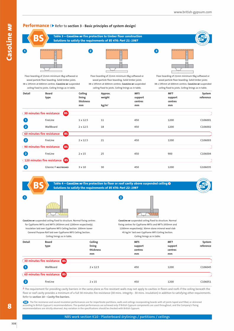
Table 4 – CasoLine MF fire protection to floor or roof cavity above suspended ceilingSolutions to satisfy the requirements of BS 476: Part 22: 1987
Table 3 – CasoLine MF fire protection to timber floor constructionSolutions to satisfy the requirements of BS 476: Part 21: 1987
308
www.british-gypsum.comCa
soLi
ne
MF
8NBS work section K10 - Plasterboard drylinings / partitions / ceilings
1
Detail Board Ceiling Approx. MF5 MF7 System
type lining weight support support reference
thickness centres centres
mm kg/m2 mm mm
FireLine 1 x 12.5 11 450 1200 C106001
WallBoard 2 x 12.5 18 450 1200 C106002
FireLine 2 x 12.5 21 450 1200 C106003
FireLine 2 x 15 25 450 900 C106004
Glasroc F MULTIBOARD 3 x 10 30 450 1200 G1060353
2
2
2
1
120 minutes fire resistance
Detail Board Ceiling MF5 MF7 System
type lining support support reference
thickness centres centres
mm mm mm
WallBoard 2 x 12.5 450 1200 C106045
FireLine 2 x 15 450 1200 C106051
1
2
1 The requirement for providing cavity barriers in the same plane as fire-resistant walls may not apply to cavities in floors and roofs if the ceiling beneath the
floor or roof cavity provides a minimum of a full 30 minutes fire resistance (30 mins. integrity : 30 mins. insulation) in addition to satisfying other requirements.
Refer to section 10 – Cavity fire barriers.
The fire resistance and sound insulation performances are for imperforate partitions, walls and ceilings incorporating boards with all joints taped and filled, or skimmedaccording to British Gypsum’s recommendations. The quoted performances are achieved only if British Gypsum components are used throughout, and the Company’s fixingrecommendations are strictly observed. Any variation in the specifications should be checked with British Gypsum.
NB
1
CasoLine MF suspended ceiling fixed to structure. Normal fixing centres
for Gypframe MF5s and MF7s (450mm and 1200mm respectively).
Insulation laid over Gypframe MF5 Ceiling Section. 100mm Isover
General Purpose Roll laid over Gypframe MF5 Ceiling Section.
Ceiling linings as in table.
Floor boarding of 21mm minimum t&g softwood or
wood particle floor boarding. Solid timber joists.
38 x 195mm at 600mm centres. CasoLine MF suspended
ceiling fixed to joists. Ceiling linings as in table.
Performance ( Refer to section 3 - Basic principles of system design)
60 minutes fire resistance BS
30 minutes fire resistance BS
90 minutes fire resistance BS
30 minutes fire resistance
60 minutes fire resistance BS
BS
BS
BS
BS 1
2
CasoLine MF suspended ceiling fixed to structure. Normal
fixing centres for Gypframe MF5s and MF7s (450mm and
1200mm respectively). 30mm stone mineral wool slab
45 kg/m3 laid over Gypframe MF5 Ceiling Section.
Ceiling linings as in table.
LIF
ET
IME
S Y S T E M W
AR
RA
NT
Y
SPECSURE
LIF
ET
IME
S Y S T E M W
AR
RA
NT
Y
SPECSURE
2
Floor boarding of 21mm minimum t&g softwood or
wood particle floor boarding. Solid timber joists
38 x 195mm at 600mm centres. CasoLine MF suspended
ceiling fixed to joists. Ceiling linings as in table.
3
Floor boarding of 21mm minimum t&g softwood or
wood particle floor boarding. Solid timber joists
38 x 195mm at 600mm centres. CasoLine MF suspended
ceiling fixed to joists. Ceiling linings as in table.

Table 5 – CasoLine MF fire protection to steel beams supporting concrete floorsSolutions to satisfy the requirements of BS 476: Part 23: 1987
309
T 0844 800 1991 F 0844 561 8816 E [email protected]
Caso
Lin
e M
F
8NBS work section K10 - Plasterboard drylinings / partitions / ceilings
1
Detail Board Ceiling Approx. MF5 MF7 System
type lining weight support support reference
thickness centres centres
mm kg/m2 mm mm
WallBoard 2 x 12.5 18 450 1200 C100013
FireLine 1 x 12.5 11 450 1200 C100014
Glasroc F MULTIBOARD 1 x 12.5 12 450 1200 G100036
Glasroc F MULTIBOARD 2 x 10 20 400 1200 G100038
FireLine 2 x 15 25 450 900 C1000152
2
1
1
2
CasoLine MF ceiling suspended beneath steel beams
supporting a concrete floor. Ceiling linings as in table.
BS 1
30 minutes fire resistance
60 minutes fire resistance BS
BS
120 minutes fire resistance BS
1 Concrete floors as described in BS 476: Part 23. The steel beams subjected to test had a section factor A/V (Hp/A) of 205m-1 calculated on the basis of three
sided profiled exposure. The suspended ceiling will also provide adequate protection to steel beams with a lower section factor.
LIF
ET
IME
S Y S T E M W
AR
RA
NT
Y
SPECSURE
2
CasoLine MF ceiling suspended beneath steel beams
supporting a concrete floor. Ceiling linings as in table.

310
www.british-gypsum.comCa
soLi
ne
MF
8NBS work section K10 - Plasterboard drylinings / partitions / ceilings
Performance ( Refer to section 3 - Basic principles of system design)
1 3
CasoLine MF ceiling suspended
beneath basic floor to give 240mm
cavity. Ceiling linings as in table.
CasoLine MF ceiling suspended beneath basic floor to
give 240mm cavity, with 100mm Isover Spacesaver
Ready-Cut in cavity. Ceiling linings as in table.
4
CasoLine MF ceiling suspended beneath basic floor to
give 240mm cavity, with 100mm Isover Spacesaver
Ready-Cut in cavity. Ceiling linings as in table.
Detail Board Ceiling Approx. Sound insulation System
type lining weight Airborne Impact reference
thickness Rw (Rw + Ctr) Lnw
mm kg/m2 dB dB
WallBoard 1 x 12.5 10 56 (50) 68 C100016
WallBoard 2 x 12.5 18 58 (51) 66 C100017
SoundBloc 1 x 12.5 13 61 (51) 60 C100018
SoundBloc 2 x 12.5 23 64 (55) 57 C1000194
3
2
1
1 Basic floor construction is lightweight concrete joist floor with insulated concrete infill panel (surface density of infill is 90kg/m2) and total depth 150mm.
Sound insulation is Rw 35 dB (airborne) and Lnw 91 dB (impact).
The fire resistance and sound insulation performances are for imperforate partitions, walls and ceilings incorporating boards with all joints taped and filled, or skimmedaccording to British Gypsum’s recommendations. The quoted performances are achieved only if British Gypsum components are used throughout, and the Company’s fixingrecommendations are strictly observed. Any variation in the specifications should be checked with British Gypsum.
NB
Sound insulation
2
CasoLine MF ceiling suspended
beneath basic floor to give 240mm
cavity. Ceiling linings as in table.
Table 6 – CasoLine MF upgrading the sound insulation of concrete floors 1
LIF
ET
IME
S Y S T E M W
AR
RA
NT
Y
SPECSURE

Table 7 – CasoLine MF upgrading the fire resistance and sound insulation of timber floorsSolutions to satisfy the requirements of BS EN 1365-2: 2000 (where applicable) and BS 476: Part 21: 1987
311
T 0844 800 1991 F 0844 561 8816 E [email protected]
Caso
Lin
e M
F
8NBS work section K10 - Plasterboard drylinings / partitions / ceilings
Detail Board Ceiling Approx. Floor Sound insulation System
type lining weight depth Airborne Impact reference
thickness Rw (Rw + Ctr) Lnw
mm kg/m2 mm dB dB
SoundBloc 2 x 12.5 23 320 60 60 C106007
SoundBloc 2 x 12.5 23 320 63 (51) 57 C106009
SoundBloc 2 x 12.5 23 320 63 (55) 54 C106013
SoundBloc 2 x 12.5 23 376 66 (54) 50 C106011
SoundBloc 2 x 15 27 325 60 60 C106014
FireLine 2 x 12.5 21 320 62 (53) 55 C106022
SoundBloc 2 x 15 27 325 63 (55) 54 C106023
SoundBloc 2 x 15 27 381 66 (54) 50 C106025
SoundBloc 2 x 15 27 336 63 (55) 51 C106026
FireLine 2 x 15 25 325 59 61 C106004
FireLine 2 x 15 25 325 62 (53) 55 C106024
4
3
2
1
5
4
3
3
1
3
1
1 Basic floor construction is 45mm x 195mm timber joists at 600mm centres with 21mm t&g wood chipboard flooring.2 18mm t&g wood chipboard spot bonded to Gyproc Plank on Isover Sound Deadening Floor Slab laid on overlining of 12mm plywood.
The fire resistance and sound insulation performances are for imperforate partitions, walls and ceilings incorporating boards with all joints taped and filled, or skimmedaccording to British Gypsum’s recommendations. The quoted performances are achieved only if British Gypsum components are used throughout, and the Company’s fixingrecommendations are strictly observed. Any variation in the specifications should be checked with British Gypsum.
NB
CasoLine MF ceiling suspended beneath basic floor (ceiling
removed) to give 277mm cavity. 100mm Isover Spacesaver
Ready-Cut laid on ceiling boards. Ceiling linings as in table.
CasoLine MF ceiling suspended beneath basic floor
(ceiling removed) with a layer of Gyproc Plank fixed
to the underside of the chipboard to give a 258mm
cavity. 100mm Isover Spacesaver Ready-Cut laid
on ceiling boards. Ceiling linings as in table.
CasoLine MF ceiling suspended beneath basic floor
(ceiling removed) using Gypframe Acoustic Hangers to
give 277mm cavity. 100mm Isover Spacesaver Ready-Cut
laid on ceiling boards. Ceiling linings as in table.
New floating floor2 laid over joists. CasoLine MF ceiling
suspended beneath 195mm x 45mm timber joists at 600mm
centres to give 277mm cavity. 100mm Isover Spacesaver
Ready-Cut laid on ceiling boards. Ceiling linings as in table.
1 2
4 5
3
CasoLine MF ceiling suspended beneath
GypFloor SILENT using Gypframe Acoustic Hangers to give
277mm cavity. 100mm Isover Spacesaver Ready-Cut
laid on ceiling boards. Ceiling linings as in table.
60 minutes fire resistance EN BS
30 minutes fire resistance
90 minutes fire resistance
LIF
ET
IME
S Y S T E M W
AR
RA
NT
Y
SPECSURE
EN BS1
BS
BS

312
www.british-gypsum.comCa
soLi
ne
MF
8
System reference C10A014
C10A015
System reference C10A016
C10A017
QUATTRO 47
QUATTRO 46
Gyptone QUATTRO 46
Gyptone QUATTRO 46 plus 100mm Isover Spacesaver Ready-Cut
Practical absorption coefficient αp
125 250 500 1k 2k 4k αw AC1 NRC2
0.65 0.60 0.55 0.45 0.40 0.35 0.45(L) D 0.50
0.60 0.60 0.65 0.55 0.45 0.40 0.50(L) D 0.55
Gyptone QUATTRO 47
Gyptone QUATTRO 47 plus 50mm Isover APR 1200
Practical absorption coefficient αp
125 250 500 1k 2k 4k αw AC1 NRC2
0.45 0.50 0.45 0.40 0.30 0.25 0.35(L) D 0.40
0.50 0.55 0.50 0.40 0.30 0.30 0.40(L) D 0.45
QUATTRO 41
Gyptone QUATTRO 41
Practical absorption coefficient αp
125 250 500 1k 2k 4k αw AC1 NRC2
0.50 0.70 0.80 0.70 0.60 0.55 0.65 C 0.70
System reference C10A091
Table 8 – Sound absorption data for Gyptone boards - tested on a 400mm plenum
Gyptone QUATTRO 45
Gyptone QUATTRO 45 plus 50mm Isover APR 1200
Practical absorption coefficient αp
125 250 500 1k 2k 4k αw AC1 NRC2
0.15 0.30 0.60 0.70 0.65 0.50 0.60 C 0.60
0.40 0.70 0.80 0.80 0.70 0.60 0.75 C 0.75
1 AC – Absorption Class.2 NRC – Noise Reduction Coefficient.
For further information on sound absorption performance of Gyptone boards, refer to British Gypsum Ceiling Products Acoustic Performance Data publication, available todownload from www.british-gypsum.com
All products have been tested to BS EN 20354 and ISO 354. The single figure rating practical sound absorption coefficient αw is calculated in accordance with EN ISO 11654. Suffix letters indicate where performance is limited at either low, medium or high frequencies.NB
NB
QUATTRO 45 Sound absorption coefficient αp
0.0
0.2
0.4
0.6
0.8
1.0
125 250 500 1000 2000 4000
Prac
tica
l abs
orpt
ion
coe
ffic
ient
αp
Frequency (Hz)
System reference C10A106
C10A107
Sound absorption coefficient αp
0.0
0.2
0.4
0.6
0.8
1.0
125 250 500 1000 2000 4000
Prac
tica
l abs
orpt
ion
coe
ffic
ient
αp
Frequency (Hz)
Sound absorption coefficient αp
0.0
0.2
0.4
0.6
0.8
1.0
125 250 500 1000 2000 4000
Prac
tica
l abs
orpt
ion
coe
ffic
ient
αp
Frequency (Hz)
Sound absorption coefficient αp
0.0
0.2
0.4
0.6
0.8
1.0
125 250 500 1000 2000 4000
Prac
tica
l abs
orpt
ion
coe
ffic
ient
αp
Frequency (Hz)

313
T 0844 800 1991 F 0844 561 8816 E [email protected]
Caso
Lin
e M
F
8
Gyptone LINE 6
Gyptone LINE 6 plus 100mm Isover Spacesaver Ready-Cut
Practical absorption coefficient αp
125 250 500 1k 2k 4k αw AC1 NRC2
0.70 0.65 0.60 0.50 0.40 0.35 0.45(L) D 0.55
0.70 0.70 0.65 0.65 0.50 0.45 0.55(L) D 0.65System reference C10A001
C10A002
System reference C10A018
C10A019
LINE 7 Curve
LINE 6
Gyptone LINE 7 Curve
Gyptone LINE 7 Curve plus 100mm Isover Spacesaver Ready-Cut
Practical absorption coefficient αp
125 250 500 1k 2k 4k αw AC1 NRC2
0.70 0.65 0.60 0.50 0.40 0.35 0.45(L) D 0.55
0.70 0.70 0.65 0.65 0.50 0.45 0.55(L) D 0.65
Table 8 (continued) – Sound absorption data for Gyptone boards - tested on a 400mm plenum
Sound absorption coefficient αp
0.0
0.2
0.4
0.6
0.8
1.0
125 250 500 1000 2000 4000
Prac
tica
l abs
orpt
ion
coe
ffic
ient
αp
Frequency (Hz)
Sound absorption coefficient αp
0.0
0.2
0.4
0.6
0.8
1.0
125 250 500 1000 2000 4000
Prac
tica
l abs
orpt
ion
coe
ffic
ient
αp
Frequency (Hz)
1 AC – Absorption Class.2 NRC – Noise Reduction Coefficient.
For further information on sound absorption performance of Gyptone boards, refer to British Gypsum Ceiling Products Acoustic Performance Data publication, available todownload from www.british-gypsum.com
All products have been tested to BS EN 20354 and ISO 354. The single figure rating practical sound absorption coefficient αw is calculated in accordance with EN ISO 11654. Suffix letters indicate where performance is limited at either low, medium or high frequencies.NB
NB

314
www.british-gypsum.comCa
soLi
ne
MF
8
Rigitone 8/18 (plenum depth 50mm)
Rigitone 8/18 (plenum depth 200mm)
Rigitone 8/18 (plenum depth 200mm plus 50mm Isover Frame Batt 32)
Practical absorption coefficient αp
125 250 500 1k 2k 4k αw AC1 NRC2
0.10 0.30 0.65 0.85 0.55 0.30 0.50(M) D 0.55
0.35 0.75 0.90 0.60 0.50 0.40 0.55(LM) D 0.70
0.60 0.95 0.95 0.80 0.70 0.50 0.70(LM) C 0.85
System reference C10A036
C10A037
C10A060
System reference C10A038
C10A039
C10A061
System reference C10A040
C10A041
C10A062
15/30
10/23
8/18
Rigitone 10/23 (plenum depth 50mm)
Rigitone 10/23 (plenum depth 200mm)
Rigitone 10/23 (plenum depth 200mm plus 50mm Isover Frame Batt 32)
Practical absorption coefficient αp
125 250 500 1k 2k 4k αw AC1 NRC2
0.10 0.25 0.65 0.90 0.55 0.25 0.45(M) D 0.60
0.35 0.70 0.85 0.60 0.50 0.35 0.50(LM) D 0.65
0.65 0.95 0.90 0.80 0.65 0.45 0.65(LM) C 0.85
Rigitone 15/30 (plenum depth 50mm)
Rigitone 15/30 (plenum depth 200mm)
Rigitone 15/30 (plenum depth 200mm plus 50mm Isover Frame Batt 32)
Practical absorption coefficient αp
125 250 500 1k 2k 4k αw AC1 NRC2
0.10 0.25 0.60 0.85 0.55 0.30 0.45(M) D 0.55
0.35 0.70 0.85 0.60 0.50 0.35 0.50(LM) D 0.65
0.60 0.95 1.00 0.85 0.70 0.55 0.70(LM) C 0.85
Sound absorption coefficient αp
0.0
0.2
0.4
0.6
0.8
1.0
125 250 500 1000 2000 4000
Prac
tica
l abs
orpt
ion
coe
ffic
ient
αp
Frequency (Hz)
Sound absorption coefficient αp
0.0
0.2
0.4
0.6
0.8
1.0
125 250 500 1000 2000 4000
Prac
tica
l abs
orpt
ion
coe
ffic
ient
αp
Frequency (Hz)
Sound absorption coefficient αp
0.0
0.2
0.4
0.6
0.8
1.0
125 250 500 1000 2000 4000
Prac
tica
l abs
orpt
ion
coe
ffic
ient
αp
Frequency (Hz)
1 AC – Absorption Class.2 NRC – Noise Reduction Coefficient.
For further information on sound absorption performance of Gyptone boards, refer to British Gypsum Ceiling Products Acoustic Performance Data publication, available todownload from www.british-gypsum.com
All products have been tested to BS EN 20354 and ISO 354. The single figure rating practical sound absorption coefficient αw is calculated in accordance with EN ISO 11654. Suffix letters indicate where performance is limited at either low, medium or high frequencies.NB
NB
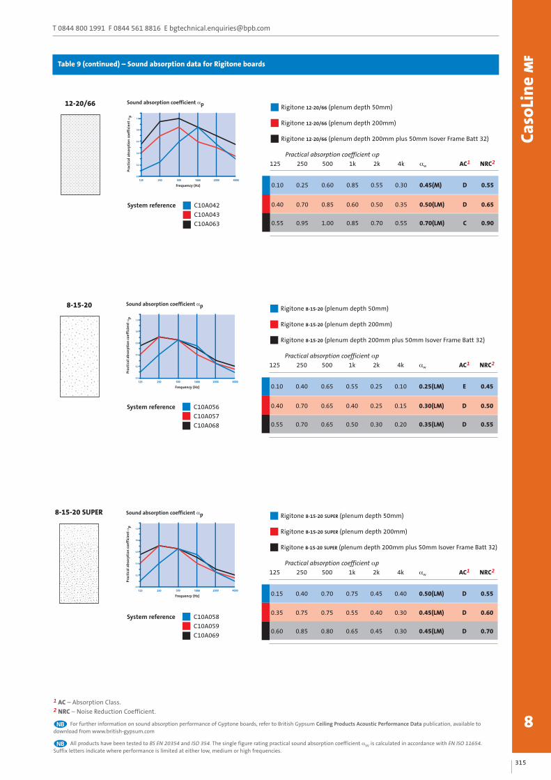
Table 9 – Sound absorption data for Rigitone boards
315
T 0844 800 1991 F 0844 561 8816 E [email protected]
Caso
Lin
e M
F
8
System reference C10A042
C10A043
C10A063
12-20/66
System reference C10A056
C10A057
C10A068
8-15-20
System reference C10A058
C10A059
C10A069
8-15-20 SUPER
Rigitone 12-20/66 (plenum depth 50mm)
Rigitone 12-20/66 (plenum depth 200mm)
Rigitone 12-20/66 (plenum depth 200mm plus 50mm Isover Frame Batt 32)
Practical absorption coefficient αp
125 250 500 1k 2k 4k αw AC1 NRC2
0.10 0.25 0.60 0.85 0.55 0.30 0.45(M) D 0.55
0.40 0.70 0.85 0.60 0.50 0.35 0.50(LM) D 0.65
0.55 0.95 1.00 0.85 0.70 0.55 0.70(LM) C 0.90
Rigitone 8-15-20 (plenum depth 50mm)
Rigitone 8-15-20 (plenum depth 200mm)
Rigitone 8-15-20 (plenum depth 200mm plus 50mm Isover Frame Batt 32)
Practical absorption coefficient αp
125 250 500 1k 2k 4k αw AC1 NRC2
0.10 0.40 0.65 0.55 0.25 0.10 0.25(LM) E 0.45
0.40 0.70 0.65 0.40 0.25 0.15 0.30(LM) D 0.50
0.55 0.70 0.65 0.50 0.30 0.20 0.35(LM) D 0.55
Rigitone 8-15-20 SUPER (plenum depth 50mm)
Rigitone 8-15-20 SUPER (plenum depth 200mm)
Rigitone 8-15-20 SUPER (plenum depth 200mm plus 50mm Isover Frame Batt 32)
Practical absorption coefficient αp
125 250 500 1k 2k 4k αw AC1 NRC2
0.15 0.40 0.70 0.75 0.45 0.40 0.50(LM) D 0.55
0.35 0.75 0.75 0.55 0.40 0.30 0.45(LM) D 0.60
0.60 0.85 0.80 0.65 0.45 0.30 0.45(LM) D 0.70
Sound absorption coefficient αp
0.0
0.2
0.4
0.6
0.8
1.0
125 250 500 1000 2000 4000
Prac
tica
l abs
orpt
ion
coe
ffic
ient
αp
Frequency (Hz)
Sound absorption coefficient αp
0.0
0.2
0.4
0.6
0.8
1.0
125 250 500 1000 2000 4000
Prac
tica
l abs
orpt
ion
coe
ffic
ient
αp
Frequency (Hz)
Sound absorption coefficient αp
0.0
0.2
0.4
0.6
0.8
1.0
125 250 500 1000 2000 4000
Prac
tica
l abs
orpt
ion
coe
ffic
ient
αp
Frequency (Hz)
1 AC – Absorption Class.2 NRC – Noise Reduction Coefficient.
For further information on sound absorption performance of Gyptone boards, refer to British Gypsum Ceiling Products Acoustic Performance Data publication, available todownload from www.british-gypsum.com
All products have been tested to BS EN 20354 and ISO 354. The single figure rating practical sound absorption coefficient αw is calculated in accordance with EN ISO 11654. Suffix letters indicate where performance is limited at either low, medium or high frequencies.NB
NB
Table 9 (continued) – Sound absorption data for Rigitone boards

316
www.british-gypsum.comCa
soLi
ne
MF
8Please refer to section 3 - Basic principles of system design for general guidance
Design
Cavity barriersWhere cavity barriers are required, these can be formed using GyprocFireLine or Glasroc F MULTIBOARD screw-fixed to a simple metal ortimber frame. The framing should be fixed to the structure to avoidundue loading of the ceiling suspension grid or, alternatively,additional hangers should be incorporated to support the ceilingalongside the cavity barrier.
Refer to section 10 – Cavity fire barriers.
Relative humidity
CasoLine MF ceilings lined with Gyproc, Gyptone, Rigitone or
British Gypsum specialist boards are suitable for use under normal
occupancy conditions. Buildings in which they are used should be
dry, glazed and enclosed, with environmental conditions of no
greater than 70% RH at 10°C to 20°C. For high humidity / high
moisture conditions use Gyproc plasterboard MR variants or
Glasroc F MULTIBOARD.
Vapour control
For areas other than where perforated Gyptone or Rigitone boards
are used, a face layer of DUPLEX grade plasterboard or two coats of
Gyproc Drywall Sealer applied to the face of the lining will provide
water vapour control.
Acoustic performance
Gyptone and Rigitone boards are perforated and designed to provide
sound absorption when used in conjunction with an airspace behind
the ceiling. Increased levels of sound absorption can be achieved by
including insulation over the back of the ceiling. Where sound
insulation room-to-room is required, sound attenuation (Dncw) of
39 dB can be achieved by the inclusion of 100mm Isover Spacesaver
Ready-Cut over the back of the ceiling. Alternatively, other design
considerations should be adopted such as extending adjoining
partitions into the plenum void or installing a plenum barrier.
Thermal performanceIsover insulation can be laid over the suspension grid to provide therequired standard of thermal insulation. Contact the BritishGypsum Drywall Academy for further guidance.
Ceiling lift
Changes to Building Regulations Approved Document L,
airtightness requirements within dwellings, can lead to greater
changes in air pressure when a door is opened. The ceiling is
normally the lightest fixed element in the room, and therefore
most likely to be affected by this change in pressure.
This can cause the ceiling to lift, which may create a noise. Whilst
this noise can be annoying to the occupier, it has no detrimental
effect on the performance of the ceiling.
The designer should consider incorporating a pressure release
system to minimise the risk of ceiling lift. Where sufficient
‘pressure relief’ cannot be designed in, it is recommended that the
Gypframe MF5 Ceiling Section and the Gypframe MF7 Primary
Support Channel should be screw-fixed together using two Gyproc
Wafer Head Jack-Point Screws at each intersection, particularly
where non-perforated board linings are specified.
Suspension - Gyproc, British Gypsum specialist and Gyptone board linings
Fixing points for suspending the metal grid are required at
1200mm centres in each direction. Suitable fixing devices should
be employed when fixing to the structure.
The ceiling grid can be suspended from a concrete soffit using
Gypframe MF12 Soffit Cleats and Gypframe MF8 Strap Hanger, or
alternatively, Gypframe GA1 Steel Angle. The latter provides a more
robust suspension support, which restricts any flexing of the lining
when pressure is applied from below. Gypframe GA1 Steel Angle is
thus the preferred suspension option when a plaster finish is
specified to Gyproc boards. If Gypframe GA1 Steel Angle is used, it
is recommended that it is fixed to the soffit via Gypframe MF12
Soffit Cleats.
If fixing Gypframe GA1 Steel Angle direct to the soffit, the angle is
cut and bent to fit. However, this will reduce the maximum loads
that the grid is capable of supporting by 25%. Furthermore, fixing
Gypframe GA1 Steel Angles direct is not suitable if the ceiling is
likely to deflect due to varying pressures and is not suitable for
fixing to a sloping substrate.
Gypframe Acoustic Hangers can be used to suspend the grid from
timber joists to maximise the degree of acoustic isolation (see
Construction details – 7). In a comparative test a 3 dB improvement
in airborne sound insulation and a 6 dB improvement in impact
sound insulation were achieved. See Table 7, Construction details
2 and 4, relating to double layer Gyproc SoundBloc linings. With
concrete floors the high mass of the construction means that high
levels of acoustic performance can be achieved when the CasoLine MF
ceiling is suspended by conventional means, i.e. Gypframe MF8
Strap Hangers or Gypframe GA1 Steel Angle.
Suspension - Rigitone board linings
Gypframe MF7 Primary Support Channels are fixed at 1000mm
centres. Fixing points to the structure for the Gypframe MF7
Primary Support Channels are required at 900mm centres.
In addition to this, the Gypframe MF5 Ceiling Section should be
installed at nominal 330mm centres.
Partition to suspended ceiling junction
In situations where a GypWall metal stud partition passes through
a CasoLine MF ceiling, which is to both sides of the partition and
appropriately fixed to both this partition and perimeter partitions /
walls, consideration can be given to the lateral restraint provided
by the ceiling when developing the partition specification.
The relevant maximum height is the greater of the floor to
CasoLine MF ceiling or ceiling to structural soffit height. Care should
be taken during installation of tall partitions so as to not adversely
affect their performance. Contact the British Gypsum Drywall
Academy for further guidance.
Where a GypWall metal stud partition is fixed to the framework of
a CasoLine MF ceiling, in accordance with British Gypsum’s
installation instructions, the permissible maximum height is equal
to that of where it is fixed direct to a structural soffit of the same
height.

317
T 0844 800 1991 F 0844 561 8816 E [email protected]
Caso
Lin
e M
F
8
Imposed loads
Tables 11, 12 and 13 provide loading data for the suspension
grid for Gyproc, British Gypsum specialist, Gyptone and Rigitone
boards respectively. Maximum loads will be reduced by 25% when
Gypframe GA1 Steel Angle is fixed directly to the soffit (modified
loads are shown in brackets).
Table 10 – Maximum recommended loads on CasoLine MF withGyproc or British Gypsum specialist board linings
Maximum load including Suspension MF72
weight of board and any point channel
insulation centres centres
MF51 at 450mm centres
kg/m2 (modified load) mm mm
60 (45) 1200 600
40 (30) 1200 900
35 (26) 900 1200
30 (23) 1200 1200
1 Gypframe MF5 Ceiling Section.
2 Gypframe MF7 Primary Support Channel.
Table 11 – Maximum recommended loads on CasoLine MF withGyptone board linings
Maximum load including Suspension MF72
weight of board and any point channel
insulation centres centres
MF51 at 600mm centres
kg/m2 (modified load) mm mm
55 (41) 1200 600
35 (26) 1200 900
25 (19) 1200 1200
1 Gypframe MF5 Ceiling Section.
2 Gypframe MF7 Primary Support Channel.
Table 12 – Maximum recommended loads on CasoLine MF withRigitone board linings
Maximum load including Suspension MF72
weight of board and any point channel
insulation centres centres
MF51 at 330mm centres
kg/m2 (modified load) mm mm
30 (23) 900 1000
1 Gypframe MF5 Ceiling Section.
2 Gypframe MF7 Primary Support Channel.
Services
The plenum can be used to route all service requirements including
ducting, pipework, electrical cables and conduit. Where light
fittings, access panels and similar components are incorporated as
part of the design requirements, consideration must be given to
maintaining the integrity of the ceiling to meet fire resistance and
sound insulation requirements.
Fixtures
Fixings to the system should always be made into the metal grid or
to supplementary framing. Some adjustment of the primary grid
may be required to support particularly heavy loads, see Tables 11,
12 and 13. Where loads outside this range are anticipated,
independent suspension should be provided from the structure.
Control joints
Gyproc Control Joints may be required in the ceiling to relieve
stresses induced by expansion and contraction of the structure.
It is recommended that they coincide with movement joints within
the surrounding structure.
Rigitone expansion joints
Rigitone boards should be cut 10mm short of the perimeter wall
and should not be fixed to the perimeter channel, see Construction
details – 12 - 13.
Board finish
Additional care and attention should be exercised when jointing
Rigitone boards so as not to fill the perforations and impair the
acoustic performance of the finished ceiling.
Refer to section 13 – Finishing systems and decorative effects.
Please refer to section 3 - Basic principles of system design for general guidance
1

318
www.british-gypsum.comCa
soLi
ne
MF
8
Construction details
Gyproc plasterboard or British Gypsum specialist board
Gypframe MF5 Ceiling Section
Gypframe MF6 Perimeter Channel
Gypframe MF7 Primary Support Channel
Gypframe MF8 Strap Hanger or Gypframe GA1 Steel Angle
Gyproc Wafer Head Jack-Point Screw
Gypframe MF11 Nut and Bolt
Gypframe MF12 Soffit Cleat123
Bulkhead - screw-fixed3
4
567
Change of level - screw-fixed4
Perimeter perpendicular to Gypframe MF5 Ceiling Section
- screw-fixed2Perimeter parallel to Gypframe MF5 Ceiling Section
- screw-fixed1
8
8
7
5
2
4
6
3
1
5
2
4
6
3
1
Max. 150mmMax
. 150
0mm
Max. 150mm
Max
. 150
0mm
Max. 150mm
5
4
2
1
3
6
3
5
4
2
1
6

319
T 0844 800 1991 F 0844 561 8816 E [email protected]
Caso
Lin
e M
F
8
Reflected ceiling plan - single layer
Gyproc plasterboard or British Gypsum specialist board
Gypframe MF5 Ceiling Section
Gypframe MF6 Perimeter Channel
Gypframe MF7 Primary Support Channel
Gypframe MF8 Strap Hanger or Gypframe GA1 Steel Angle
1
5
Reflected ceiling plan - double layer6
2345
1
2
3
4
5
1
2
3
4
5

320
www.british-gypsum.comCa
soLi
ne
MF
8
Suspension from timber joist using Gypframe Acoustic Hangers
Gyproc plasterboard or British Gypsum specialist board
Gypframe MF5 Ceiling Section
Gypframe MF6 Perimeter Channel
Gypframe MF7 Primary Support Channel
Gypframe MF8 Strap Hanger or Gypframe GA1 Steel Angle
Gyproc Wafer Head Jack-Point Screw
Gypframe MF11 Nut and Bolt
Gypframe MF12 Soffit Cleat
Gypframe Acoustic Hanger fixed with two Gyproc Drywall Timber Screws
M6 bolt and locking nut (by others)
Timber joist floor
Isover insulation
Gypframe GA1 Steel Angle
Gyproc Profilex Access Panel
1
7
234
567
89
11121314
10
Gyproc Profilex Access Panel installation8
9
8
7
5
4
6
12
2
1
35m
m
2
4
1
3
14
13
11
10
321
T 0844 800 1991 F 0844 561 8816 E [email protected]
Caso
Lin
e M
F
8
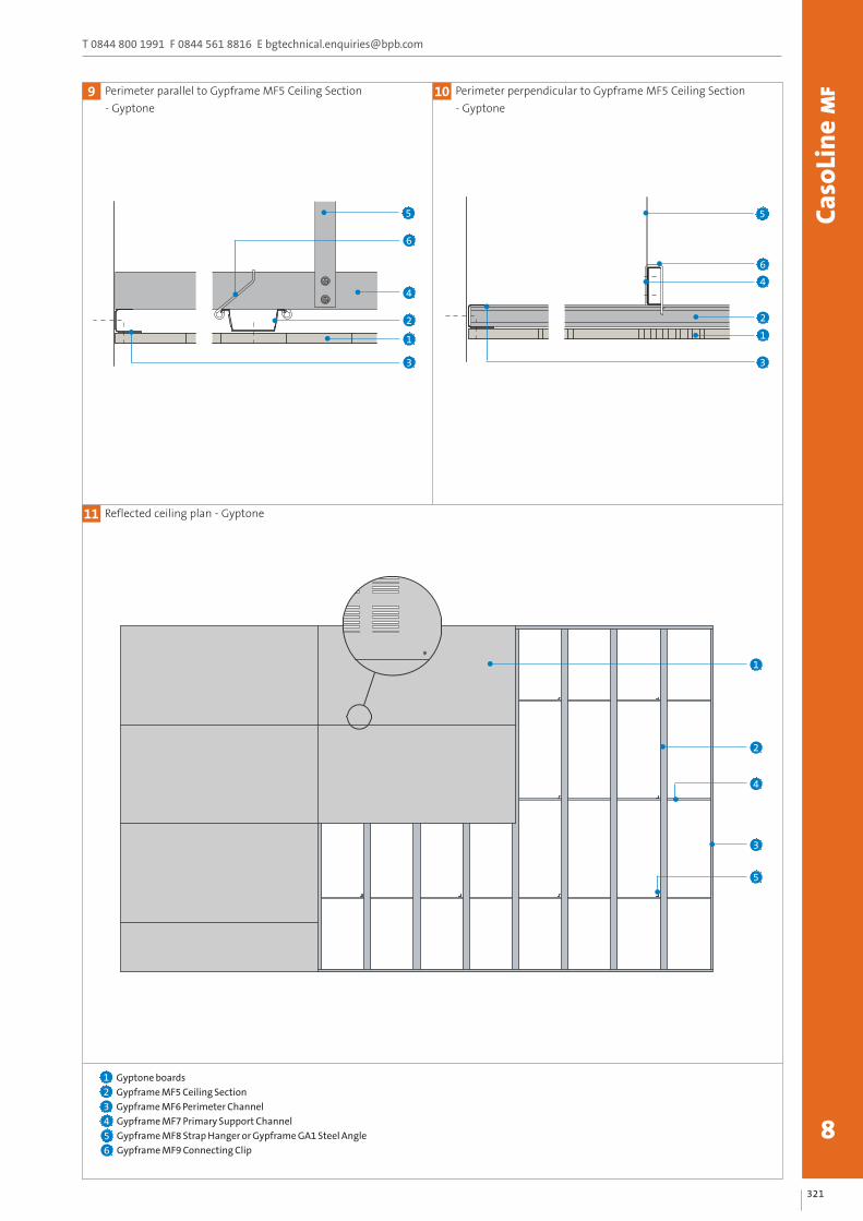
Perimeter parallel to Gypframe MF5 Ceiling Section
- Gyptone9 Perimeter perpendicular to Gypframe MF5 Ceiling Section
- Gyptone10
Reflected ceiling plan - Gyptone11
Gyptone boards
Gypframe MF5 Ceiling Section
Gypframe MF6 Perimeter Channel
Gypframe MF7 Primary Support Channel
Gypframe MF8 Strap Hanger or Gypframe GA1 Steel Angle
Gypframe MF9 Connecting Clip
123456
1
2
3
4
5
5
4
1
3
2
6
5
6
4
3
2
1

322
www.british-gypsum.comCa
soLi
ne
MF
8
Perimeter parallel to Gypframe MF5 Ceiling Section
- Rigitone
Rigitone boards
Gypframe MF5 Ceiling Section
Gypframe MF6 Perimeter Channel
Gypframe MF7 Primary Support Channel
Gypframe MF8 Strap Hanger or Gypframe GA1 Steel Angle
Gypframe MF9 Connecting Clip
Rigitone Vario 60 filler
1
12
234
567
Perimeter perpendicular to Gypframe MF5 Ceiling Section
- Rigitone13
Reflected ceiling plan - Rigitone14
A special procedure is used for fixing and jointing Rigitone boards. Detailed installation notes are given in the current British Gypsum Ceilings Installation Guide, available todownload from www.british-gypsum.comNB
1
2
3
4
5
5
2
1
7
5
6
7
4
Max. 450mm
Max. 150mm
4
6
3
2
1