
Where power meets precision de periodos de tiempo específicos El PX8000 permite la captura de...
20
Where power meets precision PX8000 Precision power scope Bulletin PX8000-01-S-E
Transcript of Where power meets precision de periodos de tiempo específicos El PX8000 permite la captura de...

Where powermeets precisionPX8000Precision power scope
Bulletin PX8000-01-S-E

El PX8000 reúne junto a la experiencia del lider mundial Yokogawa en la fabricación de analizadores de potencia, la larga tradición en el diseño de osciloscopios, para ofrecer al usuario una verdadera revolución en test y medida: el primer osciloscopio de potencia en el mundo de máxima precisión.
Con el lanzamiento del PX8000, los profesionales del I+D verán como en un único equipo se cubren las necesidades que pudieran tener en medidas de potencia en el tiempo con alta precisión.
Cuánto más avanza la innovación, centrándose en el consumo de energía e integración de electrónica basada en potencia, más y más demandan los ingenieros exactitud y precisión en sus medidas de potencia.
EL PX8000 ofrece:
Comprensión – Medir potencia con precisión ofrece verdadera comprensión del consumo de la energía y el rendimiento.
Confianza – Probada. La alta calidad de producción significa que se puede confiar en el PX8000 durante mucho tiempo.
Familiaridad – El tiempo de aprendizaje para el usuario es corto, ya que mantiene características similares a cualquier analizador de potencia u osciloscopio.

Medida de periodos de tiempo específicos
El PX8000 permite la captura
de formas de onda de potencia
durante periodos específicos de
tiempo a través de la definición
de cursores de comienzo y fin.
Esto es particularmente útil
para examinar los fenómenos
transitorios y en el diseño
de equipos controlados
periodicamente. Para garantizar
que equipos tales como una
fotocopiadora cumple con
los estándares de energía,
por ejemplo, es vital medir el
consumo de energía a través
de los diferentes rangos de
funcionamiento: desde “parado”
hasta su actividad máxima,
así como todos los estados
intermedios de funcionamiento.
Medida y análisis de transitoriosde potencia
Característicasy Beneficios
Cálculos de Potencia Simultánea
El PX8000 realiza la
multiplicación de tensión y
corriente simultánea para
dar el cálculo de potencia en
tiempo real. Además de realizar
medidas transitorias (viene de
serie) y medidas de valores
numéricos promediados en todo
el periodo de muestreo.
El periodo de medida disponible
dependerá de la frecuencia
de muestreo y el tamaño de la
memoria.
Medidas de tendencias de potencia ciclo a ciclo
Las medidas de tendencias
entre formas de onda se
pueden calcular por funciones
matemáticas (hasta 4 millones
de puntos). El PX8000 ofrece
en pantalla gráficas como
voltaje, corrientes y potencias.
Las formas de onda se pueden
inspeccionar por valores
numéricos específicos en
cualquier punto y los promedios
se pueden calcular entre los
cursores de comienzo y fin.
Estas capacidades son
especialmente importantes
cuándo se analiza y se quiere
optimizar el rendimiento, por
ejemplo, de motores eléctricos
e iluminación en el momento de
su arranque.
Pantalla X-Y y análisis de fase
Para ciertas aplicaciones
es importante ser capaz de
mostrar los valores en un eje
XY. Los motores por ejemplo
se caracterizan por una curva
en ST dónde se muestra la
relación entre velocidad y
torque. El PX8000 ofrece dicha
visualización de serie. También
puede mostrar las formas de
onda de Lissajous de entrada y
salida para el análisis fasorial.
El PX8000 tiene una serie de características innovadoras que le ayudaran en las medidas y análisis de perfiles de potencia.
Características y Beneficios PX8000
2

Capturando fenómenos inesperados
Fenómenos anormales
descubiertos durante repetidas
mediciones de alta frecuencia
son a menudo difíciles de aislar,
desapareciendo de la pantalla
casi tan rápido como aparecen.
El PX8000 tiene siempre
activa la función Histórico que
automáticamente almacena hasta
1,000 formas de onda anteriores.
Estas formas de onda se pueden
recuperar y volver a visualizar en
cualquier momento. También se
pueden utilizar para redefinir las
condiciones de disparo.
Las formas de onda del Histórico
se pueden explorar a través de
búsquedas basadas en ciertas
condiciones. Los fenómenos
anormales se pueden localizar,
por ejemplo, para las formas
de onda que se cruzan - o no
se cruzan - en una cierta zona
rectangular. Otros parámetros de
búsqueda incluyen la amplitud de
la forma de onda y el valor RMS.
Análisis y captura de datos en largos periodos
El PX8000 viene acompañado
de una aplicación de PC
llamada PowerViewerPlus que
se puede utilizar para capturar
formas de onda y analizar
a posteriori. Esto amplía la
posibilidad del PX8000 de usar
funciones matemáticas para
analizar el comportamiento en
largos periodos de tiempo. La
conexión a PC es via Ethernet/
USB/GP-IB. El software es
muy amigable y muestra las
formas de onda en un simple y
claro gráfico similar al popular
Xviewer de Yokogawa.
Los investigadores que quieran
utilizar su propio software de
análisis se podrán conectar con
el PX8000 a través de drivers de
Labview sin problemas.
Medida simultánea de armónicos
El PX8000 permite medir
simultáneamente los armónicos
de corriente y voltaje así como
la distorsión armónica. Las
mediciones de armónicos
tienen lugar en paralelo con
las medidas convenciones de
tensión y corriente. El equipo
mide hasta armónicos de orden
500.
Análisis FFT
Las caracterísitcas del PX8000
aritméticas, desfase de tiempos,
FFT y otros cálculos permiten
a los usuarios visualizar las
formas de onda con las
correcciones de offset y desfase
correspondientes. Los usuarios
también pueden definir sus
propios cálculos mediante
ecuaciones que combinan
diferenciales, integrales, filtros
digitales y una gran cantidad de
otras funciones.
3

El PX8000en detalle
Selección de visualización:
Amplia gama de funciones de
visualización para el análisis de
potencia incluyendo gráficos numérico/
forma de onda/vector/barras/XY.
Configuración de adquisición:
Ajuste de tamaño de memoria y de la
función histórico para mostrar y analizar
formas de onda irregulares. La frecuencia
de muestreo se ajusta automáticamente
según el tamaño de memoria y del eje de
tiempos elegidos.
Configuración de parámetros de los
módulos:
Los parámetros y opciones de medida
incluyen rangos de voltaje/corriente (directo/
sensor), auto-rango, offset, zoom vertical,
filtro, escalado y sincronización de fuentes.
Configuración de análisis de potencia:
Funciones analíticas incluyen cálculos
de tendencia ciclo a ciclo, medidas de
periodos de tiempo específicos, análisis de
armónicos y FFT. Hay una configuración
específica para la captura de las
condiciones de entrada del sensor.
Configuración del Sistema de
Cableado:
Configurable entre las diferentes
posibilidades según los sistemas
eléctricos más relevantes:
1P2W/1P3W/3P3W/3P3W(3V3A)/3P4W).
1
2
3
4
5
The PX8000 in detail PX8000

1 32
4
5

Módulos
1 2
1
2
3
3
Ajuste del de-skew
Los sensores pueden introducir errores de fase o desfases
entre las entradas de corriente y voltaje. El kit deskew701936
permite corregir de forma automática e individual este desfase
para cada uno de los elementos de potencia.
Módulo de Voltage
12-bit, frecuencia de muestreo hasta 100MS/s
Ancho de Banda desde DC a 20MHz (-3dB)
Entrada directa desde 1.5V a 1000Vrms
Precisión de 45Hz a 1kHz: 0.1% de lectura, +0.1% de rango
Módulo de Corriente
12-bit, frecuencia de muestreo hasta 100MS/s
Ancho de Banda de DC a 10MHz (-3dB, entrada directa)
Ancho de Banda DC a 20MHz (-3dB, sensor entrada de voltaje)
Entrada directa de 10mA a 5Arms
Entrada de sensor de 50mV a 10Vrms
Precisión de 45Hz a 1kHz: 0.1% de lectura, +0.1% de rango
El elemento de medida de potencia incluye módulo de
voltaje y corriente (hasta 4 módulos)
Módulo de medida de voltaje y sensor
(hasta 3 módulos se pueden instalar)
Módulo auxiliar (AUX)
12 bit, frecuencia de muestreo hasta 100 MS/s
Ancho de banda desde DC a 20MHz (-3dB)
Hasta 200V (DC+ACpeak) entrada directa
Hasta 1000V (DC+ACpeak) usando sonda
Precisión: 0.5% del rango (DC)
Entrada sensor torque y velocidad
Pulso de entrada desde 1.8Hz a 1MHz
Características de prevención de error y seguridad
Para evitar incompatibilidades, el PX8000 detectará si
los módulos de tensión y corriente no son compatibles
y avisará con un mensaje de advertencia en la pantalla.
El PX8000 también viene con un rango de conectores
dedicados de entrada estándar diseñados para evitar
conexiones eléctricas incorrectas o peligrosas. Usando
estos conectores, no es posible, por ejemplo, conectar una
sonda de corriente a un terminal de entrada de tensión.
Un sistema tie-wrap previene de una desconexión
accidental del terminal.
Módulos
6
PX8000

Conectividad
1
2
3
4
5
6
7
8
9
10
11
1 VIDEO OUT
Salida de señal de video para mejorar la
visualización en pantallas analógicas RGB
2 GP-IB
Interface de bus de propósito general
3 IRIG
Sincroniza múltiples instrumentos mediante
una fuente externa de tiempo (opcional)
4 EXT I/O
El PX8000 puede usarse para enviar una señal
go/no-go basada en unas condiciones; del
mismo modo que señales externas se pueden
usar como disparo para analizar medidas.
5 Ranura de tarjetas SD
SD y SDHC.
6 USB-PC
Permite el control desde un PC
7 USB
Para conectar diversos
periféricos incluyendo pendrives,
teclado y ratón.
8 Ethernet
1000BASE-T se incluye estándar
9 TRIGGER IN
Entrada de tirgger externa
10 TRIGGER OUT
Salida de trigger externa
11 EXT CLK IN
El muestreo puede sincronizarse a una
señal externa (de hasta 9.5 MHz)
Conectividad
7
Captura de fenómenos de larga duración
La gran capacidad de memoria interna de hasta 100 Millones
de puntos permite realizar medidas de larga duración
realizadas a altas frecuencias de muestreo.

Potencia ligadaa precisiónEquipos de I+D de todo el mundo están llegando a un acuerdo en la necesidad para los nuevos niveles de precisión en la medición de potencia. Con el generalizado control por microprocesador y la continua presión para reducir el consumo de la energía, las líneas entre la ingeniería eléctrica y electrónica continúan difuminándose - y la necesidad para una nueva clase de medidas híbridas está emergiendo.Los instrumentos de medida de potencia tradicionales no proporcionan mediciones en el tiempo precisas; y los osciloscopios no están diseñados para medir potencia. El PX8000 es el primer osciloscopio de potencia de máxima precisión en el mundo. La precisión basada en el tiempo del PX8000 trae a una nueva dimensión las medidas y análisis de potencia . Este nuevo modelo puede capturar con gran precisión formas de onda de tensión y corriente, abriendo las puertas a aplicaciones y soluciones para una gran variedad de problemas en medidas de potencia emergentes.
Centrándose en la Precisión
El PX8000 ofrece medidas de potencia de formas de onda con alta precisión. Entre las características únicas del PX8000 podemos destacar:
Imágenes multifunciónHasta 16 formas de onda-incluyendo voltaje, corriente y potencia- se pueden mostrar simultáneamente, dando a los ingenieros imágenes instantáneas del rendimiento.
Análisis de transitorios detalladasEl PX8000 soporta las medidas de todos los parámetros de formas de onda de potencia con precisión entre cursores de comienzo y fin.
Cálculo de tendenciaEl PX8000 tiene funciones predefinidas para el cálculo directo de variables, tales como RMS y la media de los valores de potencia, para permitir la identificación de tendencias ciclo a ciclo.
Compensación De-skew
isoPRO TM - Tecnologíade medida pionera
El PX8000 funciona con tecnología de Yokogawa isoPRO TM, que ofrece un rendimiento de aislamiento líder enla industria a las más altas velocidades de adquisición. La tecnología de núcleo isoPRO TM, diseñado con la mente puesta en aplicaciones de ahorro de energía, ofrece el rendimiento necesario para desarrollar inversores de alta eficiencia que trabajen a altos voltajes, grandes corrientesy altas frecuencias.
La familia de analizadores de potencia Yokogawa
El PX8000 es el nuevo producto estrella para la gama de analizadores de potencia Yokogawa. El primer instrumento de medida de potencia de Yokogawa fue fabricado en los años 1960, y sus analizadores de potencia han jugado un papel importante desde entonces en el desarrollo industrial.
8
Potencia ligada a precisión PX8000

Centrándose en potencia
Los investigadores de todo el mundo se están centrando en las cuestiones clave que sólo pueden responderse mediante medidas precisas de potencia.
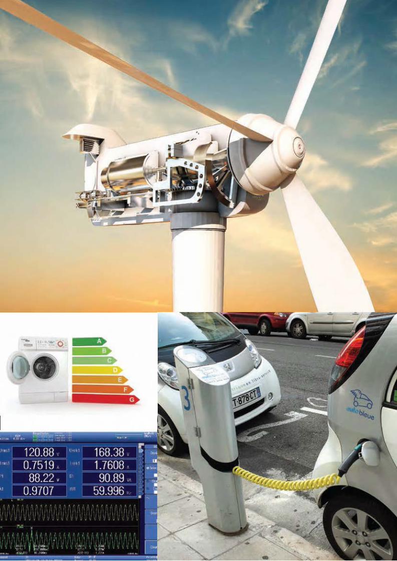
Cómo podemos minimizar pérdidas de energía?Cómo podemos mejorar el rendimiento?Cómo podemos utilizar eficientemente las fuentesde energía renovables?
Celdas fotovoltáica para energía solar Soluciones para redes inteligentes
Vehículos eléctricos/híbridos Carga de energía inalámbrica
Eficiencia y rendimiento del inversor
Centrándose en potencia
Los investigadores de todo el mundo se están centrando en las cuestiones clave que sólo pueden responderse mediante medidas precisas de potencia.
Cómo podemos minimizar pérdidas de energía?Cómo podemos mejorar el rendimiento?Cómo podemos utilizar eficientemente las fuentesde energía renovables?
Celdas fotovoltáica para energía solar Soluciones para redes inteligentes
Vehículos eléctricos/híbridos Carga de energía inalámbrica
Eficiencia y rendimiento del inversor
Planta de Potencia Virtual Planta de Potencia
Central
Celdas de Energía
Casas Inteligentes
Oficinas
Plantas Industriales
Turbinas Eólicas
Almacenamiento
Microturbinas
9
Potencia ligada a precisión
9
Potencia ligada a precisión

AplicacionesEl PX8000 es un instrumento inmensamente versátil, posibilitando medidas de precisión de potencia para investigadores que trabajen desde la potencia de energía renovable a la robótica avanzada. En cualquier lugar el consumo de energía hay que tenerlo en cuenta, ya que en casi cualquier lugar se consume energía, y se pueden beneficiar del uso de las capacidades del PX8000 de medida y análisis de potencia.Las siguientes páginas cubren algunas aplicaciones típicas para el PX8000. Para ayudarle en el diseño de su propia estrategia de medida, por favor, póngase en contacto con su
habitual representante de Yokogawa.
Aplicaciones
10
PX8000

Pruebas Motor e InversorSituación actual
Los vehículos eléctricos e híbridos tienen muchos componentes eléctricos y mecánicos; y la evaluación general requiere de medición de eficiencia de ambos. La flexibilidad, precisión y ancho de banda del PX8000 lo hace ideal para estudiar todas las lecturas de potencia necesarias para optimizar la eficiencia de los circuitos boost y los inversores - dos elementos claves en el rendimiento general del vehículo eléctrico.
La Ventaja del PX8000
Gran Ancho de BandaLa resolución vertical del conversor analógico/digital es uno de los factores más importantes para medir con mucha precisión. El PX8000 tiene 12 bit de resolución vertical con una frecuencia de muestreo de 100 MS/s y 20 MHz de ancho de banda. Esto quiere decir que el PX8000 puede usarse para medidas precisas de formas de pulsos del inversor, que luego se pueden utilizar para, de forma fina, ajustar la eficiencia del inversor.
Medidas de Transitoriosen tendencias ciclo a cicloLa capacidad del PX8000 de analizar las tendencias ciclo a ciclo lo hace ideal para medir los efectos de transitorios. Durante la fase de puesta en marcha, o arranque, de un inversor o motor, por ejemplo, la corriente incrementa y puede ser analizada en cada ciclo. Y cuando las cargas cambian rápidamente, los ingenieros pueden obtener conocimientos del comportamiento que les permitirán mejorar el controldel inversor.
Análisis Armónicos y FFTEl PX8000 puede medir tanto armónicos como FFT para análisis basadas en frecuencia. La función Armónico puede medir formas de onda de frecuencia fundamentales desde 20 Hz hasta 6.4 KHz Esto es particularmente útil para el análisis de las componentes altas en frecuencia y las causas de ruido en sistemas electromecánicos.
Cancelación de offset individualFunción NULLUn problema común al probar los motores del inversor es la presencia de ruido ambiente que puede significar que los valores de prueba son distintos de cero, incluso antes de que comience la prueba. Las capacidades de offset del PX8000 sirven para que tales efectos puedan ser anulados y entradas específicas pueden ser aisladas para probarlas y analizarlas.
Pruebas Motore InversorSituación actual
Los vehículos eléctricos e híbridos tienen muchos componentes eléctricos y mecánicos; y la evaluación general requiere de medición de efi ciencia de ambos. La fl exibilidad, precisión y ancho de banda del PX8000 lo hace ideal para estudiar todas las lecturas de potencia necesarias para optimizar la efi ciencia de los circuitos boost y los inversores - dos elementos claves en el rendimiento general del vehículo eléctrico.
La Ventaja del PX8000
Gran Ancho de BandaLa resolución vertical del conversor analógico/digital es uno de los factores más importantes para medir con mucha precisión. El PX8000 tiene 12 bit de resolución vertical con una frecuencia de muestreo de 100 MS/s y 20 MHz de ancho de banda. Esto quiere decir que el PX8000 puede usarse para medidas precisas de formas de pulsos del inversor, que luego se pueden utilizar para, de forma fi na, ajustar la efi ciencia del inversor.
Medidas de Transitoriosen tendencias ciclo a cicloLa capacidad del PX8000 de analizar las tendencias ciclo a ciclo lo hace ideal para medir los efectos de transitorios. Durante la fase de puesta en marcha, o arranque, de un inversor o motor, por ejemplo, la corriente incrementa y puede ser analizada en cada ciclo. Y cuando las cargas cambian rápidamente, los ingenieros pueden obtener conocimientos del comportamiento que les permitirán mejorar el controldel inversor.
Análisis Armónicos y FFTEl PX8000 puede medir tanto armónicos como FFT para análisis basadas en frecuencia. La función Armónico puede medir formas de onda de frecuencia fundamentales desde 20 Hz hasta 6.4 KHz Esto es particularmente útil para el análisis de las componentes altas en frecuencia y las causas de ruido en sistemas electromecánicos.
Cancelación de offset individualFunción NULLUn problema común al probar los motores del inversor es la presencia de ruido ambiente que puede signifi car que los valores de prueba son distintos de cero, incluso antes de que comience la prueba. Las capacidades de offset del PX8000 sirven para que tales efectos puedan ser anulados y entradas específi cas pueden ser aisladas para probarlas y analizarlas.
-0.005
-0.000
0.005
0.010
0.015
0.020
0.025
0.030
0.035
0.040
Frecuencia (Hz)
Ext 2Vx5V
10 100 1000 10000 100000 1000000
0.5Ax15V 0.2Ax150V
-0.006
-0.004
-0.002
0
0.002
0.004
0.006
0.008
0.01
Rango 5A
1 10 100 1000 10000 100000 1000000
Rango Ext 2V Rango 150V Rango 0.2Ax150V
-1
01
2
3
4
5
6
7
Freq (Hz)
100V range
10 100 1000 10000 100000 1000000 10000000
5A range 10V range
-1
01
2
3
4
5
6
7
Freq (Hz)
100V range
10 100 1000 10000 100000 1000000 10000000
5A range 10V range
Pre
cisi
ón m
edid
a co
mo
un %
de
rang
oP
reci
sión
med
ida
com
o un
% d
el r
ango
Frecuencia (Hz)
Precisión medida como un % del rango vs frecuencia (Hz), con factor de potencia=1.
Pruebas Motor e Inversor
11
Entrada
Temperaturas Voltaje/Corriente
MotorSensor de
torque/velocidad
Carga
Sección inversor
Modulador y convertidor señales DC a AC
Velocidad/Torque
BateríasCircuito
dispositivo
Sección de convertidor
booster
PX8000
1 3 42
(1) Medida de energía de baterías(2) Medida de efi ciencia del circuito boost(3) (4) Medida de efi ciencia del sistema inversor sobre la medida del comportamiento transitorio
Pruebas Motor e Inversor
11
Entrada
Temperaturas Voltaje/Corriente
MotorSensor de
torque/velocidad
Carga
Sección inversor
Modulador y convertidor señales DC a AC
Velocidad/Torque
BateríasCircuito
dispositivo
Sección de convertidor
booster
PX8000
1 3 42
(1) Medida de energía de baterías(2) Medida de eficiencia del circuito boost(3) (4) Medida de eficiencia del sistema inversor sobre la medida del comportamiento transitorio

Medidas de pérdidas del reactor de los circuitos boost del inversorSituación actual
Un reactor se utiliza para filtrar el ruido de salida y aumentar
los niveles de tensión antes de la utilización del inversor. Se
compone de un núcleo de material electromagnético y una
bobina. Un foco principal para ingenieros eléctricos es reducir
las pérdidas de potencia del sistema total del inversor. Hay
dos métodos de evaluación potenciales: medir las pérdidas
directamente del reactor y medir la pérdida del hierro. El
PX8000 soporta cualquiera de los métodos, ya que puede
adaptarse tanto a la medición a alta frecuencia como a las
condiciones de bajo factor de potencia.
Ventaja del PX8000
Medición de bajo factor de potenciaVelocidades de muestreo más altas y un amplio ancho de banda hacen al PX8000 especialmente útil para dispositivos de prueba, tales como transformadores y reactores, que tienen menor factor de potencia. Es particularmente importante para medir el consumo de potencia de los dispositivos a altas frecuencias.
Funcionalidad De-skewPara analizar consumos de potencia en dispositivos con bajo factor de potencia es especialmente importante minimizar cualquier diferencia de tiempos entre tensiones y corrientes causados por las caracterísitcas de entrada del sensor. El PX8000 ofrece un preciso ajuste de-skew para compensar esta diferencia de tiempos.
Medidas de pérdidas de núcleo a altas frecuenciasEl análisis de pérdidas en el núcleo de un reactor es un ejemplo de cómo las funciones matemáticas definidas por el usuario del PX8000 se pueden utilizar para proporcionar un análisis instantáneo del rendimiento del sistema. En este ejemplo, las pérdidas en el núcleo se calculan basándose en la corriente de la bobina primaria y el voltaje de la bobina secundaria (usando lecturas de un dispositivo de Epstein), mientras que la densidad de flujo magnético (B) y el campo magnético (H) se calculan utilizando la frecuencia de entrada, el área de sección transversal y otros parámetros. Todos estos valores se pueden mostrar directamente en el PX8000.
Medida de Corriente
Medida de Voltaje
N2N1Alimentación
Variable
PX8000
Reactor Inversor
PX8000
Items medidos usando las funciones de usuario siguientes:
B =
(H) =
Voltaje (media)
N1 x corriente de pico de bobina primaria
Pérdidas de núcleo = Valor de potencia (W) x
2 ∏ x Frecuencia de corriente x N2 x Sección de cruce
Longitud efectiva de camino magnético
N1
N2
Medidas de pérdidas del reactor de los circuitos boost del inversor
PX8000
12

Respuestas transitorias de robots industrialesSituación actual
Para evaluar los robots accionados por motor, el consumo de potencia de todos los motores y controladores son medidos a lo largo de todas las velocidades de operación y patrones de acción. Los ingenieros de diseño necesitan medir el voltaje, corriente y potencia varias veces y en diferentes escenarios para establecer el patrón. La eficiencia se calcula comparando mecánicamente la potencia de salida con la entrada.Durante las condiciones de funcionamiento reales, el tiempo para acelerar y desacelerar los motores pueden variar desde cientos de milisegundos a varios segundos. Como un motor PWM rota desde la posición de reset a la velocidad máxima, su frecuencia puede variar desde DC hasta cientos Hz.El PX8000 muestra a los ingenieros de diseño el consumo de energía y la eficiencia a lo largo de los diferentes modos de operación y funcionamiento de un robot.
Ventaja del PX8000
Análisis de un periodo de tiempo específicoEl PX8000 puede medir formas de onda entre cursores específicos de comienzo/fin. Combinado con su capacidad multicanal y sus funciones de memoria e histórico, convierte al PX8000 en un equipo especialmente útil para estudiar el consumo de potencia en los modos de operación de un robot.
Medidas de eficiencia en boosters, inversores y motores Una sóla unidad del PX8000 puede medir tanto la potencia de entrada y salida de inversores y la salida mecánica de un motor. Instalando tres unidades de potencia y un módulo AUX, el PX8000 se puede configurar para proporcionar medidas instantáneas de las componentes de la eficiencia.
Medida transitoria en tendenciasCon sus cálculos de potencia instantánea, el PX8000 es ideal para evaluar y optimizar efectos transitorios. Su análisis de tendencia ciclo a ciclo proporciona una importante información en esta área crucial de ingenería robótica.
Medidas de periodos de tiempos más largos Para analizar algunas operaciones robóticas, puede ser necesario analizar tendencias ciclo a ciclo durante un largo periodo de tiempo. El software PowerViewerPlus amplía esta capacidad matemática para permitir un estudio más detallado y profundo de los datos obtenidos.
PX8000
Otros motoresRobot
MotorControlador de
RobotPin
PSalida
Transient responses of industrial robots
13

Ventaja del PX8000
Evaluación de eficiencia de carga inalámbricaPara evaluar la eficiencia de carga inalámbrica (incluyendo inversores), se requieren al menos tres elementos de medición de potencia. El PX8000, con sus cuatro canales de entrada, puede analizar el rendimiento de todo el sistema de forma simultánea.
Medidas de dispositivos de bajo factor de potenciaLa alta frecuencia de muestreo del PX8000 y el amplio ancho de banda lo convierte en el equipo ideal para sistemas de transmisión de energía inalámbrica. El PX8000 soporta una resolución de 12 bits, frecuencias de muestreo de hasta 100 MS/s y un ancho de banda de 20MHz. Fundamentalmente, esto signiifica que el PX8000 es compatible con la medición de los sistemas de bajo factor de potencia que funcionan a
frecuencias muy altas.
Funcionalidad de-skewEl PX8000 incluye la función de-skew, que le permite al usuario compensar las diferencias de tiempo, desfases, entre tensiones y corrientes, que puedan ser originadas por sensores y por sus caracterísitcas de entrada. Con el PX8000 se pueden compensar y eliminar del análisis de sistemas de bajo factor de
potencia.
DC PowerSupply
Signal Oscillator
Inverter Capacitor Oscillate Coil Receive Coil Capacitor
Load (Non-inductive)
Q2
Q1
D1 C3
D2C4
PX8000
Ventaja del PX8000
Evaluación de efi ciencia de carga inalámbricaPara evaluar la efi ciencia de carga inalámbrica (incluyendo inversores), se requieren al menos tres elementos de medición de potencia. El PX8000, con sus cuatro canales de entrada, puede analizar el rendimiento de todo el sistema de forma simultánea.
Medidas de dispositivos de bajo factor de potenciaLa alta frecuencia de muestreo del PX8000 y el amplio ancho de banda lo convierte en el equipo ideal para sistemas de transmisión de energía inalámbrica. El PX8000 soporta una resolución de 12 bits, frecuencias de muestreo de hasta 100 MS/s y un ancho de banda de 20MHz. Fundamentalmente, esto signiifi ca que el PX8000 es compatible con la medición de los sistemas de bajo factor de potencia que funcionan a
frecuencias muy altas.
Funcionalidad de-skewEl PX8000 incluye la función de-skew, que le permite al usuario compensar las diferencias de tiempo, desfases, entre tensiones y corrientes, que puedan ser originadas por sensores y por sus caracterísitcas de entrada. Con el PX8000 se pueden compensar y eliminar del análisis de sistemas de bajo factor de
potencia.
DC PowerSupply
Signal Oscillator
Inverter Capacitor Oscillate Coil Receive Coil Capacitor
Load (Non-inductive)
Q2
Q1
D1 C3
D2C4
PX8000
-0.005
-0.000
0.005
0.010
0.015
0.020
0.025
0.030
0.035
0.040
Frecuencia (Hz)
Ext 2Vx5V
10 100 1000 10000 100000 1000000
0.5Ax15V 0.2Ax150V
-0.006
-0.004
-0.002
0
0.002
0.004
0.006
0.008
0.01
Rango 5A
1 10 100 1000 10000 100000 1000000
Rango Ext 2V Rango 150V Rango 0.2Ax150V
-1
01
2
3
4
5
6
7
Freq (Hz)
100V range
10 100 1000 10000 100000 1000000 10000000
5A range 10V range
-1
01
2
3
4
5
6
7
Freq (Hz)
100V range
10 100 1000 10000 100000 1000000 10000000
5A range 10V range
Pre
cisi
ón m
edid
a co
mo
un %
de
rang
oP
reci
sión
med
ida
com
o un
% d
el r
ango
Frecuencia (Hz)
Precisión medida como un % de rango vs. Frecuencia (Hz), con factor de potencia=0.
Medidas de efi cienciade cargadores inalámbricosSituación actual
El desarrollo de tecnologías de carga inalámbrica para dispositivos móviles como smartphones y tablets es un foco para la investigación. Los fabricantes de automóviles también están estudiando las posibilidades de carga eléctica de vehículos de forma inalámbrica. La carga inalámbrica depende de dos bobinas electromagnéticas confi guradas para soportar perfi les de frecuencia particulares. La transferencia de energía efi ciente y la prevención de pérdidas de potencia son, naturalmente, muy importantes. el PX8000 es ideal para medir tales sistemas debido a su capacidad de operar a altas frecuencias y bajos factores de potencia.
14
Medidas de efi ciencia de cargadores inalámbricos PX8000
Medidas de eficiencia de cargadores inalámbricosSituación actual
El desarrollo de tecnologías de carga inalámbrica para dispositivos móviles como smartphones y tablets es un foco para la investigación. Los fabricantes de automóviles también están estudiando las posibilidades de carga eléctica de vehículos de forma inalámbrica. La carga inalámbrica depende de dos bobinas electromagnéticas configuradas para soportar perfiles de frecuencia particulares. La transferencia de energía eficiente y la prevención de pérdidas de potencia son, naturalmente, muy importantes. el PX8000 es ideal para medir tales sistemas debido a su capacidad de operar a altas frecuencias y bajos factores de potencia.
14
Medidas de eficiencia de cargadores inalámbricos PX8000

Distribuciónde EnergíaSituación actual
Los sistemas de distribución de energía tienen que mantener la tensión y la potencia constante durante el cambio de carga o en el caso de un cortocircuito. Los protectores de distribución o cortocircuitos para sistemas eléctricos trifásicos se deben probar a niveles de potencia y voltaje transitoria. El PX8000 puede capturar fluctuaciones de formas de onda de voltaje y corriente, calcular parámetros de potencia (incluyendo valores de tensión y corriente), determinar un promedio durante un periodo especifico y mostrar todos los valores.
Ventaja del PX8000
Captura de datos simultánea de sistemas trifásicosPara evaluar sistemas eléctricos trifásicos, se necesitan al menos tres entradas de medida de potencia. El PX8000 tiene hasta cuatro entradas y además permite la captura simultánea y visualización de la tensión y corriente de las tres fases.
Medida de periodos de tiempo específicosPara una evaluación real de una protección de distribución, es necesario medir un ciclo completo de voltaje, corriente y potencia, medio ciclo después de recuperarse del cortocircuito. El PX8000 se puede configurar fácilmente para centrarse en un periodo tan específico.
Análisis armónicos y FFT El PX8000 tiene la capacidad de medir tanto armónicos como FFT para análisis de frecuencias. La función armónica puede medir frecuencias fundamentales desde 20 Hz hasta 6.4KHz, y se puede calcular la FFT usando desde 1 punto hasta 100 mil puntos en hasta dos canales.Tales medidas son vitales para identificar armónicos de
corriente y fuentes de ruido.
Protector Protector
Protector
Protector
Corto
Voltaje
Voltaje
Voltaje
Conversor
Conversor
Conversor
Voltaje
Conversor
PX8000
Power distribution
15

Zoom Display
Zoom Expand the displayed waveform along the time axis (up to 2 separate locations). The zoom position can be automatically scrolled
FFT Display
FFT Power spectrum of input waveform, Max. two windows
X-Y display
X-Y Display The X and Y axes can be selected from Un/In/Pn/AUXn, MATHn (Max. four traces, two windows)
Measurement Function and Conditions
Crest Factor Up to 200 (effective minimum input). Up to 2 (rated input)CfU: Voltage crest factor, CfI: Current crest factor
Measurement period Measurement period to calculate numerical values– Period of measurement update cycle based on zero crossing or external
gate signal source signal – 8192 points from specified by start cursor for harmonic measurement
Wiring method 1P2W (Single phase 2 wire), 1P3W (Single phase 3 wire), 3P3W (3 phase 3 wire), 3V3A (3 phase 3 wire, 3 power meter method), 3P4W (3 phase 4 wire)
Scaling 0.0001 to 99999.9999 can be set for scaling of VT ratio, CT ratio and power ratio when external current sensor, VT or CT are used for the inputLinear scaling function is available for AUX module (760851)
Frequency measurement
Number of displayed digits Full 5 digits (99999)
Max frequency 5.0000MHz
Accuracy +/- 0.1 of reading
Frequency Measurement filter Same as Zero-cross filter (OFF/100Hz/500Hz/2kHz/20kHz)
Harmonics measurement
Method PLL synchronization method (not available for external sampling clock function)
Frequency range The range for the fundamental frequency of the PLL source is 20Hz to 6.4kHz, and sampling frequency is more than 2MS/s
FFT data length 8192, the analysis (calculation) start point can be set freely in the acquisition memory data
Window function Rectangular
Sample ranges, window width and upper limits of harmonic analysis
Fundamental freq. Sample rate Window width Upper limit of harmonics20Hz to 600Hz f*1024 8 cycles 500 order600Hz to 1200Hz f*512 16 cycles 255 order1200Hz to 2600Hz f*256 32 cycles 100 order2600Hz to 6400Hz f*128 64 cycles 50 order f:KHz
Accuracy Line filter OFFAdd below expression to normal measurementVoltage & current: ( 0.001xf + 0.001xn )% of reading + 0.1% of rangePower: (0.002xf + 0.002xn )% of reading + 0.2% of rangeWhen input frequency is over 100kHz, add:Voltage & current: 0.3% of readingPower: 0.6% of reading
Waveform data acquisition and display
Acquisition mode Normal: Normal waveform data acquisitionEnvelop: The peak values are held at the maximum sample rate regardless of the Time/div setting.Averaging: The number of times to average can be set from 2 to 65536 in 2n steps.
Zoom Expand the displayed waveform along the time axis (up to 2 separate locations). The zoom position can be automatically scrolled.
Display format 1/2/3/4/6/8/12, and 16 analog waveforms windows
Snapshot The currently displayed waveforms can be retained on the screen. Snapshot waveforms can be saved and loaded.
Time base An External Clock input is available. Please refer to Time setting
Vertical and Horizontal Control
Channel ON/OFF Un, Ιn, Pn, AUXn or MATHn can be turned ON and OFF separately
Vertical axis zooming x 0.1 to x 100Can set the scale by using upper and lower limits or switch between different scales
Roll Mode Roll mode is enabled automatically when the trigger mode is set to Auto, Auto Level, Single, or On Start, and the time axis setting is greater than or equal to 100 ms/div.
Analysis Functions
Power value calculation Calculate Voltage, Current. Power, Delta parameters, frequency and AUX values from captured waveformsApparent power, reactive power and power factor and those Sigma values are calculated from the Voltage, Current and Power values
Waveform parameters Up to 24 items can be displayedP-P, Amp, Max, Min, High, Low, Avg, Mid, Rms, Sdev, +OvrShoot, -OvrShoot, Rise, Fall, Freq, Period, +Width, -Width, Duty, Pulse,Burst1, Burst2, AvgFreq, AvgPeriod, Int1TY, Int2TY, Int1XY, Int2XY, Int1hXY (IntegPower/IntegCurrent) Int2hXY (IntegPower/IntegCurrent)
Statistic processing Application items: Automated measurement values of waveform parametersStatistical items: Max, Min, Avg, Sdv, and Cnt
Cyclic statistical processing Automatically measures the waveform parameters of the data in the acquisition memory and performs statistical processing on the parameters once per period.
User defined computation(MATH)
Max 8 expressions for waveforms MATH1 to MATH8, Max. 4 Mpoint, regarding Digital filter +, -, *, /, SHIFT, ABS, SQRT, LOG, EXP, NEG, SIN, COS, TAN, ATAN, PH, DIF, DDIF, INTG, IINTG, BIN, SQR, CUBE, F1, F2, FV, PWHH, PWHL, PWLH, PWLL, PWXX, DUTYH, DUTYL, FILT1, FILT2, HLBT, MEAN, LS-, PS-, PSD-, CS-, TF-, CH-, MAG, LOGMAG, PHASE, REAL, IMAG, TREND, TRENDM, TRENDD, TRENDF, _HH, _LL, _XX and _ZC
User defined computation(numeric)
Max. 20 expressions, F1 to F20+, -, *, /, ABS, SQRT, LOG, EXP and NEG
Phase sifting Monitors the waveform of a specified channel with its phase shifted
Desckew function Compensates the phase difference between voltage and current modules for power measurements
GO/NO-GO determination The two types of GO/NO-GO determination are available
File Functions
Save Setup data, Waveform data (including History data), Numeric data and Image data can be saved external media
Read Waveform data (including History data up to 1000 waveform) and setup data
USB Ports for Peripherals
Compatible USB storage devices
Mass storage devices that are compliant with USB Mass Storage Class Ver.1.1
USB Peripheral Interface
Number of ports 2
Electrical and mechanical specifications
USB Rev.2.0 compliant
Supported transfer mode HS (High Speed, 480Mbps), FS (Full Speed, 12Mbps), and LS (Low Speed, 1.5Mbps)
Input/OutputEXT TRIG IN
Connector type BNC
Input level TTL
Minimum pulse width 100 ns
EXT TRG OUT
Connector type BNC
Output level 5V CMOS
Logic Low when a trigger occurs and high after acquisition is completed
EXT CLK IN
Connector type BNC
Input level TTL
Minimum pulse width 50 ns
Video Signal Output
Connector type D-Sub 15 pin receptacle
Output format Analog RGB
Output resolution XGA-compliant output 1024x768 dotsApprox. 60 Hz Vsync (dot clock frequency: 66 MHz)
GO/NO-GO Determination I/O
Connector type RJ-11 modular jack
Input level TTL or contact
External Start/Stop Input
Connector type RJ-11 modular jack
Input level TTL or contact
Comp Output
Output signal frequency 1 kHz +/- 1%
Output amplitude 1 Vp-p +/- 10%
Probe Power Output (/P4 Option)
Number of output terminals 4
Output voltage +/- 12 Vdc
Output current Total max. of 1A
Time Sync Signal Input (IRIG: /C20 option)
Input connector BNC
Supported IRIG signals A002, B002, A132, and B122
Input impedance Can be switch between 50 Ohm and 5 kOhm
Maximum input voltage +/- 8 V
GP-IB
Connector type 24-pin connector
Electrical specification Complies with IEEE St’d 488-1978(JIS C 1901-1987)
Functional specification SH1, AH1, T6, L4, SR1, RL1, PP0, DC1, DT0, and C0
Protocol IEEE St'd 488.2-1992
Ethernet
Connector type RJ-45 modular jack
Transmission system Ethernet (1000BASE-T, 100BASE-TX or 10BASE-T)
Communication protocols TCP/IP
USB
Connector type USB type B receptacle
Electrical and mechanical specifications
USB Rev.2.0 compliant
Supported transfer mode HS (High Speed, 480Mbps) and FS (Full Speed, 12Mbps)
Displaying ItemsNumerical Values
Normal Measurement functions for each channel (power element)
Voltage (V) Urms: true rms value, Umn: mean value calibrated rms value, Udc: simple average value, Urmn; rectified mean value, Uac: AC component
Current (A) Irms: true rms value, Imn: mean value calibrated rms value, Idc: simple average value, Irmn; rectified mean value, Iac: AC component
Active Power (W) P
Apparent Power (VA) S (depends on Type 1, 2 or 3), Type1and Type2: selectable of Urms x Irms, Umn x Imn, Udc x Idc, Urmn x Irmn or Umn x Irms
Reactive Power (Var) Q (depends on Type 1, 2 or 3)
Power Factor Lambda (P/S)
Phase Angle (deg) Phi (cos -1 P/S)
Harmonic analysis function (Option)
Voltage (V) U(k): k-th order voltage true rms value, U: total voltage true rms value When k=0, it shows DC component
Current (A) I(k): k-th order current true rms value, I: total current true rms value When k=0, it shows DC component
Active Power (W) P(k): k-th order active power value, P: total active power value When k=0, it shows DC component
Apparent Power (VA) S(k): k-th order apparent power value, S: total apparent power value When k=0, it shows DC component
Reactive Power (Var) Q(k): k-th order reactive power value, Q: total reactive power value When k=0, it shows 0
Power Factor Lambda(k): k-th order power factor value, Lambda: total power factor value
Phase Angle (deg) Phi(k): Phase angle between k-th order voltage and current, Phi: Phase angle of current refers to voltage waveformPhiU(k): Phase angle of k-th order voltage refers to the fundamental voltage U(1)PhiI(k): Phase angle of k-th order current refers to the fundamental current I(1)
Delta Function
Voltage [V] DeltaU1 to DeltaU3, and Delta Usigma
Current [A] DeltaI
Power [W] Delta Ρ1 to Delta Ρ3, and DeltaΡSigma *Calculate each Sigma function
AUX analysis functionTorque and Speed input
AUX1 Pulse input or Analog input
AUX2 Pulse input or Analog input
AUX(1×2) Mechanical power calculation
Accuracy
Accuracy Conditionsaccuracy • Within 6 months after calibration
Voltage: Frequency Accuracy DC ±(0.2% of reading + 0.2% of range)0.1 Hz ≤ f < 10 Hz ±(0.2% of reading + 0.2% of range)10 Hz ≤ f < 45 Hz ±(0.2% of reading + 0.1% of range)45 Hz ≤ f ≤ 1 kHz ±(0.1% of reading + 0.1% of range)1 kHz < f ≤ 10 kHz ±(0.1% of reading + 0.1% of range)10 kHz < f ≤ 50 kHz ±(0.2% of reading + 0.2% of range)50 kHz < f ≤ 100 kHz ±(0.6% of reading + 0.4% of range)100 kHz < f ≤ 200 kHz ±(0.6% of reading + 0.4% of range)200 kHz < f ≤ 400 kHz ±(1% of reading + 0.4% of range)400 kHz < f ≤ 500 kHz ±((0.1 + 0.003 × f*)% of reading
+ 0.4% of range)500 kHz < f ≤ 1 MHz ±((0.1 + 0.003 × f*)% of reading
+ 4% of range)1 MHz < f ≤ 10 MHz ±((0.1 + 0.003 × f*)% of reading
+ 4% of range)
* Measurement bandwidth 20MHz (-3dB, Typical)* Accuracy over 1 MHz is design value* The unit of f in the equation for the reading error is (kHz).
Current: Direct Frequency Accuracy DC ±(0.2% of reading + 0.2% of range)0.1 Hz ≤ f < 10 Hz ±(0.2% of reading + 0.2% of range)10 Hz ≤ f < 45 Hz ±(0.2% of reading + 0.1% of range)45 Hz ≤ f ≤ 1 kHz ±(0.1% of reading + 0.1% of range)1 kHz < f ≤ 10 kHz ±(0.1% of reading + 0.1% of range)10 kHz < f ≤ 50 kHz ±(0.2% of reading + 0.2% of range)50 kHz < f ≤ 100 kHz ±(0.6% of reading + 0.4% of range)100 kHz < f ≤ 200 kHz ±(0.6% of reading + 0.4% of range)200 kHz < f ≤ 400 kHz ±(1% of reading + 0.4% of range)400 kHz < f ≤ 500 kHz ±((0.1 + 0.004 × f*)% of reading
+ 0.4% of range)500 kHz < f ≤ 1 MHz ±((0.1 + 0.004 × f*)% of reading
+ 4% of range)
* Measurement bandwidth 10MHz (-3dB, Typical)* The unit of f in the equation for the reading error is (kHz).
Sensor Frequency Accuracy
DC ±(0.2% of reading + 0.2% of range)0.1 Hz ≤ f < 10 Hz ±(0.2% of reading + 0.2% of range)10 Hz ≤ f < 45 Hz ±(0.2% of reading + 0.1% of range)45 Hz ≤ f ≤ 1 kHz ±(0.1% of reading + 0.1% of range)1 kHz < f ≤ 10 kHz ±(0.1% of reading + 0.1% of range)10 kHz < f ≤ 50 kHz ±(0.2% of reading + 0.2% of range)50 kHz < f ≤ 100 kHz ±(0.6% of reading + 0.4% of range)100 kHz < f ≤ 200 kHz ±(0.6% of reading + 0.4% of range)200 kHz < f ≤ 400 kHz ±(1% of reading + 0.4% of range)400 kHz < f ≤ 500 kHz ±((0.1 + 0.003 × f*)% of reading
+ 0.4% of range)500 kHz < f ≤ 1 MHz ±((0.1 + 0.003 × f*)% of reading
+ 4% of range)1 MHz < f ≤ 10 MHz ±((0.1 + 0.003 × f*)% of reading
+ 4% of range)
* Measurement bandwidth 20MHz (-3dB, Typical)* Accuracy over 1 MHz is design value* The unit of f in the equation for the reading error is (kHz).
Power: Direct Frequency Accuracy DC ±(0.2% of reading + 0.4% of
range)+20uAxU0.1 Hz ≤ f < 10 Hz ±(0.2% of reading + 0.2% of range)10 Hz ≤ f < 45 Hz ±(0.2% of reading + 0.1% of range)45 Hz ≤ f ≤ 1 kHz ±(0.1% of reading + 0.1% of range)1 kHz < f ≤ 10 kHz ±(0.1% of reading + 0.16% of range)10 kHz < f ≤ 50 kHz ±(0.2% of reading + 0.2% of range)50 kHz < f ≤ 100 kHz ±(0.6% of reading + 0.4% of range)100 kHz < f ≤ 200 kHz ±(1.5% of reading + 0.6% of range)200 kHz < f ≤ 400 kHz ±(1.5% of reading + 0.6% of range)400 kHz < f ≤ 500 kHz ±((0.1 + 0.006 × f*)% of reading
+ 0.6% of range)500 kHz < f ≤ 1 MHz ±((0.1 + 0.006 × f*)% of reading
+ 6% of range)
* The unit of f in the equation for the reading error is (kHz).
Sensor Frequency Accuracy DC ±(0.2% of reading + 0.4% of range)0.1 Hz ≤ f < 10 Hz ±(0.2% of reading + 0.2% of range)10 Hz ≤ f < 45 Hz ±(0.2% of reading + 0.1% of range)45 Hz ≤ f ≤ 1 kHz ±(0.1% of reading + 0.1% of range)1 kHz < f ≤ 10 kHz ±(0.1% of reading + 0.16% of range)10 kHz < f ≤ 50 kHz ±(0.2% of reading + 0.2% of range)50 kHz < f ≤ 100 kHz ±(0.6% of reading + 0.4% of range)100 kHz < f ≤ 200 kHz ±(1.5% of reading + 0.6% of range)200 kHz < f ≤ 400 kHz ±(1.5% of reading + 0.6% of range)z < f ≤ 500 kHz ±((0.1 + 0.004 × f*)% of reading
+ 0.6% of range)500 kHz < f ≤ 1 MHz ±((0.1 + 0.004 × f*)% of reading
+ 6% of range)
* The unit of f in the equation for the reading error is (kHz).* The unit of f in the equation for the reading error is (kHz).
These accuracies apply when the power factor = 1. For the complete specifications, please refer to the separate document BU PX8000-01EN.
Input
Shape Plug in input module style
Module structure Voltage module, Current module and AUX module Power element: one Voltage module and one Current module Max 8 modules (max 4 power elements) can be installedMax 3 Auxiliary (AUX) modules can be installed (at least one power element must be installed)
Max. channel number 8ch, combination of Voltage/Current modules and AUX module
Max. record length Standard 10M Points for each voltage and current regardless of the installed number of modules. The memory from individual modules cannot be combined.
50M Points for each voltage and current regardless of the installed number of modules when the /M1 option is installed.
100M Points for each voltage and current regardless of the installed number of modules when the /M2 option is installed.
Voltage/Current input modules (760811/760812) Specifications
Input terminal type Voltage: Plug-in terminal (female)
Current: Direct input: Plug-in terminal (male)External current sensor input: isolated BNC connector
Input format Voltage: Floating input, resistive voltage divider
Current: Floating input through shunt
Measurement range Voltage: 1.5/3/6/10/15/30/60/100/150/300/600/1000Vrms (crest factor=2 at rated range input)
Current: Direct input 5A)10m/20m/50m/100m/200m/500m/1/2/5Arms (Crest factor=2 at rated range input)
Current: External current sensor input)50m/100m/200m/500m/1/2/5/10Vrms (Crest factor=2)
Line filter Select from OFF, 500 Hz, 2kHz, 20 kHz, and 1 MHz.
Frequency filter Select from OFF, 100Hz, 500 Hz, 2kHz and 20 kHz.
A/D converterMax sample rate
Resolution: 12 bitConversion rate (sampling period): Approx. 10 ns. (100MS/s)For harmonic measurement, please refer to harmonic function.
AUX (auxiliary) module (760851) Specification
Number of input channels 2, switchable analog or pulse input
Input coupling AC, DC, or GND
Input format Isolated unbalanced
Frequency characteristics DC to 20 MHz (−3 dB point when sine wave of amplitude +/-3 div is applied)
Voltage-axis sensitivity setting 50 mV to 100 V (1-2-5 steps) (when using 1:1 probe attenuation)
A/D conversion resolution 12 bit (150 LSB/div)
Temperature coefficient +/- (0.1 of range)/degree (typical)
Bandwidth limit Select from OFF, 2 MHz, 1.28 MHz, 640 kHz, 320 kHz, 160 kHz, 80 kHz, 40 kHz, 20 kHz, and 10 kHzCut-off characteristics: −18 dB/Octave (when 2 MHz, Typical)
Accuracy DC: +/- (1% of range (typical)*1 Measured under the standard operating conditions
Frequency measurement range 1.8 Hz to 2 MHz
Pulse width 500ns or wider
Accuracy +/- (0.05% of reading) +/- 1 count error(10ns)
Trigger Function
Trigger mode Auto, Auto Level, Normal, Single, N Single, or On Start
Simple Trigger
Trigger source Un, Ιn, Pn, AUXn, EXT, LINE or Time n = channel number
Time Trigger Date (year, month, and day), time (hour and minute), and time interval (10 seconds to 24 hours)
Enhanced trigger
Trigger source Un, Ιn, Pn, AUXn or EXT
Trigger type A → B(N): A Delay B: Edge on A: AND: OR: B>Time: B<Time: B Time Out: B Between: T>Time T<Time: T1<T<T2: T<T1, T<T2: Wave Window
Time Base
Time axis setting (Observation time) "Time/div"
Time/div setting: 100ns/div to 1s/div (1-2-5 step), 2s/div, 3s/div, 4s/div, 5s/div, 6s/div, 8s/div, 10s/div, 20s/div, 30s/div, 1min/div and 2min/divObservation time: 1us to 1200s
Display
Display 10.4 inch TFT LCD display
Available displaying size 210.4 mm x 157.8 mm
Number of dots 1024 x 768 XGA)
Waveform displaying dot size 801 x 656 (Waveform Display)
Displaying format Combination: Max 2 types of format can be displayed Numeric 4 items/ 8 items/ 16 items/Matrix/All/Single List/Dual List/CustomWave 1/2/3/4/6/8/12/16Bar Single/Dual/TriadVector Single/DualZOOM1 and ZOOM2 (divided lower display area)FFT1 and FFT2 (divided lower display area)XY1 and XY2 (divided lower display area)
Display update Depends on the observation time and record length settings
Numerical Display
Displaying functions Please refer to Measurement function
Max digit of numeric display Selected full 5 digits (displaying 99999), or 6 digits (999999).
Waveform Display
Record lengthw Select from 100kpoint/250kpoint/500kpoint/1Mpoint/2.5Mpoint/5Mpoint/10Mpoint/25Mpoint (when /M1 or /M2 installed)/50Mpoint (when /M1 or /M2 installed)/100Mpoint (when /M2 installed)
Displaying items Maximum 16 waveformsVoltage, current and power of Element 1Voltage, current and power of Element 2. (Or AUX3 and AUX4 of Element 2)Voltage, current and power of Element 3. (Or AUX5 and AUX6 of Element 3)Voltage, current and power of Element 4. (Or AUX7 and AUX8 of Element 4)MATH 1 to MATH 8
Vector Bar Graph Display (option)
Vector display Display the phase angle between the fundamental voltage signal and fundamental current signal as a vector
Bar graph display Displays a bar graph of the amplitude of each harmonic in harmonic measurement
FFT Function
Waveform to be computed Un, Ιn, Pn, MATHn and AUXn
Number of channels 2
Computation range From the specified computation start point until the specified number of points have been computed
Computed points 1k, 2k, 5k, 10k, 20k, 50k, or 100k
Time windows Rect, Hamming, Hamming, Flattop, or Exponential
Built-in Printer (Option)
Print system Thermal line dot system
Sheet width 112mm
Storage Functions SD Card
Number of slot 1
Max. capacity 16GB
Supported cards SD and SDHC compliant memory card
17
PX8000
16
PX8000_Product Brochure_SPA.indd 16-17 10-01-14 08:51

Yokogawa’s approach to preserving the global environment Yokogawa’s electrical products are developed and produced in facilities that have received ISO14001 approval.
In order to protect the global environment, Yokogawa’s electrical products are designed in accordance with Yokogawa’s Environmentally Friendly Product Design Guidelines and Product Design Assessment Criteria.
Notice Before operating the product, read the user’s manual thoroughly for proper and safe operation.
If this product is for use with a system requiring safeguards that directly involve personnel safety, please contact the Yokogawa offices.
This is a Class A instrument based on Emission standards EN61326-1 and EN55011, and is designed for an industrial environment.Operation of this equipment in a residential area may cause radio interference, in which case users will be responsible for any interference which they cause.
Any company’s names and product names mentioned in this document are trade names, trademarks or registered trademarks of their respective companies. The User's Manuals of this product are provided by CD-ROM.
For the full specifications see Bulletin BU PX8000-02EN or
tmi.yokogawa.com/px8000
2
Section title Title Model / parts number
Product Description
758917 Test read set A set of 0.8m long, red and black test leads758922 Small alligator-clip Rated at 300V and used in a pair758929 Large alligator-clip Rated at 1000V and used in a pair758923 Safety terminal adapter (spring-hold type) Two adapters to a setB8213ZD Safety terminal adapter (screw-fastened type) Two adapters to a set.758921 Fork terminal adapter Banana-fork adapter, Two adapters to a set366924 * BNC-BNC cable 1m366925 * BNC-BNC cable 2mB9284LK External sensor cable Current sensor input connector, Length 0.5m
Due to the nature of this product, it is possible to touch its mental parts. Therefore, there is a risk of electric shock, so the product must be used with caution.
* Use these products with low-voltage circuits (42V or less).
Model Suffix Code Description
PX8000 Main framePower Code -D UL/CSA Standard PSE support 3-pin type
-F VDE standard-H GB standard-N NBR standard-Q BS standard-R AS standard
Languages -HE English menu-HG German menu-HJ Japanese menu
Options /B5 Built-in printer(112mm)/C20 IRIG function/G5 Harmonic measurement/M1 50M memory expansion*/M2 100M memory expansion*/P4 4 Outputs of probe power
*Select one of these
Name Model Description
Voltage Module 760811 Voltage module (Current module 760812 must be ordered together.)
Current Module 760812 Current module (Voltage module 760811 must be ordered together.)
AUX Module 760851 AUX module for sensor input, Torque/Speed
Name Model Description
PowerViewerPlus 760881 Viewer software dedicated for PX8000
YOKOGAWA METERS & INSTRUMENTS CORPORATIONGlobal Sales Dept. / Phone: +81-42-534-1413 Fax: +81-42-534-1426Email: [email protected]
YOKOGAWA CORPORATION OF AMERICA Phone: (1)-770-253-7000 Fax: (1)-770-254-0928YOKOGAWA EUROPE B.V. Phone: (31)-88-4641000 Fax: (31)-88-4641111YOKOGAWA ENGINEERING ASIA PTE. LTD. Phone: (65)-62419933 Fax: (65)-62412606
Subject to change without notice. ©2014, Yokogawa Meters & Instruments Corporation
16.5 11.711 23(8)355
259
180(202)
8
Unit: mm
Standard Accessories;Power cord(1 set), Front cover(1set), Rubber foot(4 sets), Cover plate assy(8 sets), Current terminal adapter(4 sets), Voltage terminal adapter(4 sets), Printer chart(1 set for /B5), Getting start guide(1 set), CD(Getting started guide, Futures guide, User’s Manual, Communication interface manual by PDF data)
701947 100:1 Isolation Probe 1000V (DC+ACpeak) CAT I
700929 10:1 Probe (for isolation BNC input)
1000V (DC+ACpeak) CAT I
701901 1:1 Safety BNC Adapter Lead (in combination with followings)
1000Vrms-CAT II
701959 Safety Mini-Clip (Hook type)
1000Vrms-CAT II, 1 set each of red and black
701954 Large Aligator-Clip (Dolphin type)
1000Vrms-CAT II, 1 set each of red and black
366926 1:1 BNC-Alligator Cable Non-isolated 42V or less 1m366961 1:1 Banana-Alligator Cable Non-isolated 42V or less 1.2mB9988AE Printer Roll Paper For PX8000, 10m x 10701902 Safety BNC-BNC
Cable (1m)1000Vrms-CAT II (BNC-BNC)
701903 Safety BNC-BNC Cable (2m)
1000Vrms-CAT II (BNC-BNC)
720911 External I/O Cable For external I/O connection701948 Plug-On Clip For 700929 and 701947701906 Long Test Clip For 700924 and 701926A1800JD Terminal For 720220 input terminal, one (1) Piece701963 Soft Carrying Case For PX8000B8213ZA Safety terminal adapter (screw-fastened type) Two adapters to a setB9317WD Wrench is attached For B8213ZD and B8213ZA700924 Differential probe 1400Vpk, 1000 Vrms- CAT II
Bulletin PX8000-01-S-E (Ed:01/b)Printed in Japan, 401(KP)