Wheelchair for physically disabled people with voice...
22
AutonomousRobots,2, 203-224 (1995) @ 1995Kluwer Academic Publishers,Boston. Manufactured in The Netherlands. Wheelchair for Physically Disabled People with Voice, Ultrasonic and Infrared Sensor Control MANUEL MAZO, FRANCISCO J. RODRIGUEZ, JOSI~ L. L,~ZARO, JESI~IS UREI~A, JUAN C. GARCIA, ENRIQUE SANTISO, PEDRO REVENGA AND J. JESI~IS GARCIA Electronics Department, University of Alcald de Henares, Ctra. Madrid-Barcelona Km 33,600,28871 Alcald de Henares, Madrid, Spain Abstract. This paper describes a wheelchair for physically disabled people developed within the UMIDAM I Project. A dependent-user recognition voice system and ultrasonic and infrared sensor systems has been integrated in this wheelchair. In this way we have obtained a wheelchair which can be driven with using voice commands and with the possibility of avoiding obstacles and downstairs or hole detection. The wheelchair has also been developed to allow autonomous driving (for example, following walls). The project, in which two prototypes have been produced, has been carried out totally in the Electronics Department of the University of Alcalfi (Spain). It has been financed by the ONCE 2. Electronic system configuration, a sensor system, a mechanical model, control (low level control, control by voice commands), voice recognition and autonomous control are considered. The results of the experiments carried out on the two prototypes are also given. Keywords: wheelchair, mobile robot, physically disabled, control, autonomous guidance, joystick, PID controller, ultrasonic and infrared sensors, micro-controller, fuzzy, speech recognition 1 Introduction The number of people who need to move around with the help of some artificial means, whether through an illness or an accident, is continually increasing. These means have to be increasingly sophisticated, tak- ing advantage of technological evolution, in order to increase the quality of life for these people and fa- cilitate their integration into the working world. In this way a contribution may be made to facilitating movement and to making this increasingly simple and vigorous, so that it becomes similar to that of peo- ple who do not suffer deficiencies. Systems already exist which respond to many of the needs of peo- ple with different degrees of incapacity (Leifer, 1981; Borenstein & Koren, 1985; Madarasz, 1986; Jin et al., 1993). However, there are still important advances to be made in this field. This justifies the numer- ous research programmes which are being carried out at the present time; the TIM MAN project (Miller & Grant, 1994; Grant, 1994), the COACH project (Gelin et al., 1993) and the SKIL guide system (Sabbe, 1993). The main reasons for their justification are as follows: a) The present high level of technology in the electronic and robotic systems permits some of the mobility problems suffered by certain people to be resolved. Electronics solves the problems very acceptably for the users. This is because the elec- tronics used is eminently suitable for coping with the needs presented. b) Unfortunately more and more people are appearing with incapacities which prevent them from carrying out normal activities. Most have serious problems related to movement. The type of artificial aid needed by a disabled person in order to move about depends, to a large extent, on the level of his incapacity. For example, in order to guide a wheelchair, various situations can be distinguished: a) If the user is capable of controlling his head or his hands, the ideal solution is the use of a joystick. b) Where there is a high level of incapacity, solutions are basically centred on the use of other means, such as the voice or eye movements. In this case, the presence of safety sensors is justified with the object of assisting the user to guide the chair (detection of obstacles, nearness to certain places, the existence of stairs, etc.). c) Only in extreme cases it is suggested that there may be a need for the chair to cover certain distances in an autonomous manner, without the need for any in- tervention on the part of the user (interest in this type of wheelchair could be in the following of prefixed
Transcript of Wheelchair for physically disabled people with voice...

Autonomous Robots, 2, 203-224 (1995) @ 1995 Kluwer Academic Publishers, Boston. Manufactured in The Netherlands.
Wheelchair for Physically Disabled People with Voice, Ultrasonic and Infrared Sensor Control
MANUEL MAZO, FRANCISCO J. RODRIGUEZ, JOSI~ L. L,~ZARO, JESI~IS UREI~A, JUAN C. GARCIA, ENRIQUE SANTISO, PEDRO REVENGA AND J. JESI~IS GARCIA
Electronics Department, University of Alcald de Henares, Ctra. Madrid-Barcelona Km 33,600,28871 Alcald de Henares, Madrid, Spain
Abstract. This paper describes a wheelchair for physically disabled people developed within the UMIDAM I Project. A dependent-user recognition voice system and ultrasonic and infrared sensor systems has been integrated in this wheelchair. In this way we have obtained a wheelchair which can be driven with using voice commands and with the possibility of avoiding obstacles and downstairs or hole detection. The wheelchair has also been developed to allow autonomous driving (for example, following walls). The project, in which two prototypes have been produced, has been carried out totally in the Electronics Department of the University of Alcalfi (Spain). It has been financed by the ONCE 2. Electronic system configuration, a sensor system, a mechanical model, control (low level control, control by voice commands), voice recognition and autonomous control are considered. The results of the experiments carried out on the two prototypes are also given.
Keywords: wheelchair, mobile robot, physically disabled, control, autonomous guidance, joystick, PID controller, ultrasonic and infrared sensors, micro-controller, fuzzy, speech recognition
1 Introduction
The number of people who need to move around with the help of some artificial means, whether through an illness or an accident, is continually increasing. These means have to be increasingly sophisticated, tak- ing advantage of technological evolution, in order to increase the quality of life for these people and fa- cilitate their integration into the working world. In this way a contribution may be made to facilitating movement and to making this increasingly simple and vigorous, so that it becomes similar to that of peo- ple who do not suffer deficiencies. Systems already exist which respond to many of the needs of peo- ple with different degrees of incapacity (Leifer, 1981; Borenstein & Koren, 1985; Madarasz, 1986; Jin et al., 1993). However, there are still important advances to be made in this field. This justifies the numer- ous research programmes which are being carried out at the present time; the TIM MAN project (Miller & Grant, 1994; Grant, 1994), the COACH project (Gelin et al., 1993) and the SKIL guide system (Sabbe, 1993). The main reasons for their justification are as follows:
a) The present high level of technology in the electronic and robotic systems permits some of the mobility problems suffered by certain people to
be resolved. Electronics solves the problems very acceptably for the users. This is because the elec- tronics used is eminently suitable for coping with the needs presented.
b) Unfortunately more and more people are appearing with incapacities which prevent them from carrying out normal activities. Most have serious problems related to movement.
The type of artificial aid needed by a disabled person in order to move about depends, to a large extent, on the level of his incapacity. For example, in order to guide a wheelchair, various situations can be distinguished:
a) If the user is capable of controlling his head or his hands, the ideal solution is the use of a joystick.
b) Where there is a high level of incapacity, solutions are basically centred on the use of other means, such as the voice or eye movements. In this case, the presence of safety sensors is justified with the object of assisting the user to guide the chair (detection of obstacles, nearness to certain places, the existence of stairs, etc.).
c) Only in extreme cases it is suggested that there may be a need for the chair to cover certain distances in an autonomous manner, without the need for any in- tervention on the part of the user (interest in this type of wheelchair could be in the following of prefixed

204 Mazo et al.
routes in hospitals, recreation centres, etc.). In this case the presence of external sensors is vital.
Another important requirement that a wheelchair has to fulfil is that of responding rapidly and efficiently to the commands of the user, independently of the method used for giving these commands.
1.1 The UMIDAM Project
Although a great deal of research work has been carried out on mobile robot applications in industry (Sitherama & Elfos, 1991; Meng & Kak, 1993; Moravec, 1985; Watanabe & Yuta, 1990; Maravall & Mazo, 1990; Mazo et al., 1992; Goto & Stentz, 1987), in agricul- ture (Eden et al., 1993), in security (Crowley, 1987), in toys (Bradley, 1980; McAlister, 1980), not so much work has been done towards aiding physically hand- icapped people (Leifer, 1981; Borenstein & Karen, 1985; Madarasz, 1986; Jin et al., 1993), basically considering people suffering from great incapacity (tetraplegics), that is, people who do not have the pos- sibility of using a joystick.
The UMIDAM project, described in this article, is orientated towards providing solutions to the need for moving around of disabled people who have great in- capacity with regard to driving. These needs and their possible solution were originally put forward by re- searchers in close collaboration with personnel from the ONCE Foundation. A summary of the initial ob- jectives is given below:
a) To design an electronic system which could be in- stalled in an of the commercially produced electric wheelchairs.
b) To make guiding the wheelchair possible by means of oral commands, as well as by using the classic joystick. The electronic interface would have to permit the chair to be further guided using other means (eye movement, etc.).
c) To incorporate a sensor safety system in the wheelchair which would permit obstacles and the presence of stairs or holes in the ground or floor to be detected°
d) The electronic system had to be open and modu- lar, in the sense that future additions could be made which would not necessarily be related to guiding the chair (the control of household electrical equip- ment, opening doors, etc.).
e) Another aspect of great importance with regard to the design was that the final prototype should be
economically priced for its later manufacture and commercialization.
f) The environment originally considered for the use of the wheelchair was homogeneous floors and ground where different types of obstacles (static and mobile) and the presence of pronounced differences in levels (such as stairs) might be encountered.
The final prototypes obtained, after three years of research and development, complied with all the char- acteristics initially required. The first phase consisted of the production of an electronic system for guiding the chair by means of a joystick and voice control, in- cluding the power interfaces for controlling the motors, speech recognition, etc. (first prototype). Later, in the second phase, a sensorial system based on ultrasonic and infrared sensors was also included combined with the strategy for assisting the guiding of the wheelchair (second prototype). In the following we refer to the sec- ond prototype, since all the options in the first prototype are included.
All the electronic system and the philosophy for functioning has been sufficiently refined to achieve the following performances:
a) To guarantee easy, comfortable driving. b) To respond to the speed requirements for a system
of this type (maximum speeds of up to 3 m/s). c) To be easily adaptable to any type of commercial
wheelchair chassis. d) To facilitate learning to handle the chair and obtain-
ing maximum efficiency. e) To guarantee practically constant speeds, to a
large extent independently of the characteristics of the surface over which the wheelchair is moving (greater or lesser roughness of the floor or ground and the slope of same) and the weight of the person using it.
f) To make the system easily configurable, on the basis of the needs of the user: activating or de-activating of the various sensors, selection of different voice patterns, selection of different speed margins, human-machine interface which permits up-to-date information on the state of tile wheelchair, etc.
g) To make it possible for the same wheelchair to be used by various people without the need for record- ing the voice patterns each time the wheelchair is to be used. This has been achieved thanks to a memory board which can be personal for each user.
h) To make the electronic system open to future addi- tions.

Fig. 1. Frontal view of the wheelchair.
i) To make decisions over stopping and reducing speed when obstacles of the presence of stairs is detected, as a function of the degree of danger supposed for the user in each case.
As previously mentioned, the UMIDAM is charac- terized by a speech recognition system, which consti- tutes the fundamental base for driving, and by a sensor system, made up of ultrasonic and infrared sensors for detecting obstacles, stairs or any pronounced irregu- larities in the floor or ground and by being able to be guided autonomously following walls. Figures 1 and 2 show the distribution of the different UMIDAM mo- dules taking these sub-systems into account.
Among the work carried out on similar problems, the following projects can be found: Tin Man (Miller & Grant, 1994; Grant, 1994), COACH (Gelin et al., 1993) and the SKIL guiding system (Sabbe, 1993),
Two prototypes were developed for the Tin Man project (Tin Man I and Tin Man II) which are char- acterized by being equipped with a complete sen- sor system (encoders, contact, IR proximity and fluxgate compass) which permits obstacles to be
Wheelchair for Physically Disabled People 205
detected and avoided, going to pre-designated places and manoeuvring through doorways and narrow or crowded areas. Present efforts in this project are be- ing centred on the preparation of a user interface at task level.
The development of a semi-autonomous wheelchair has been approached in the COACH project. The re- sult is a wheelchair guided by a joystick with the help of a sensor system formed by ultrasonic and infrared sensors. This sensor system is particularly considered for avoiding obstacles and following walls.
The SKIL guiding system is made up of ultrasonic and infrared sensors which permit obstacles to be de- tected, the opening of doors, etc. The originality of this system lies in the infrared sensors employed: the emit- ters are located on one side of the wheelchair and the receivers on the other, measurement of distances being made by triangulation.
Various common aspects exist in all the projects, including the UMIDAM:
a) They are all based on commercial wheelchairs in an attempt to make the systems developed as universal as possible.
b) Adaptations are made to the sensor systems nor- mally employed in mobile robots used for more general purposes.
c) Various operating modes are available in an attempt to cover different demands and autonomies.
d) Whatever the case, emphasis is placed on the im- portance of achieving the autonomy of a disabled person before the autonomy of the wheelchair itself.
2 UMIDAM Operating Modes
The operating modes have been defined taking into account the fact that a great deal of the design consider- ations in industrial mobile robots could be applied to robots for helping the disabled. But there are several differences between them:
1) Many mobile robots for industrial applications fol- low pre-designated routes which may be marked by ropes, paint, etc. to facilitate guiding. But the routes to be followed by robots for helping the disabled are dictated by the user according to his possibilities and for this reason have to be generic.
2) Domestic environments are very largely disordered, so the sensor system has to detect all the obstacles,

206 Mazo et al.
Fig. 2. Side view of the wheelchair.
stairs, etc. For an industrial robot the environment may be ordered most of the time the position of the fixed obstacles could be in the robot memory.
3) In a robot for the disabled, a person will always act directly over the system, so the control must be designed to follow the user, in the easiest way.
It is precisely this third point which caused the UMIDAM to be conceived with various operating modes. In this way it adapts to the various degrees of incapacity of the Users. Whatever the case, it must be remembered that the initial intention was to allow people who could not use a joystick to be able to guide the wheelchair.
There are three driving modes for the UMIDAM:
Joystick control: Control is carried out using the joy- stick in this driving mode. This mode is called "Man- ual control".
With voice commands: In this driving mode, the wheelchair is controlled by means of various voice commands. Here the sensors act as a safety means against any possible errors which the user may com- mit when giving the commands or in the unexpected presence of obstacles. The user has the possibility of activating or de-activating the sensors, either the ultrasonic or the infrared or both. This possibility of configuring the sensor system allows the user to drive
while subjected or not to the action of the sensors, in terms of the environment in which he is moving or even in his handling of the chair. This driving mode is called "Voice control".
Autonomous driving: This method of driving is con- sidered so that the wheelchair may follow walls or forward movement around obstacles. This per- mits the user to move around in certain environ- ments, such as hospitals, rehabilitation centres, etc., without the need for having to give voice com- mands constantly to the wheelchair. This mode is called "Autonomous control". In this driving mode, linear speed is modified by means of voice commands.
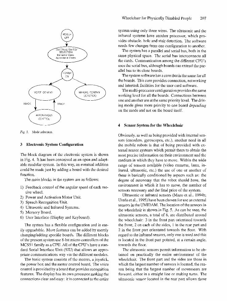
Figure 3 shows the selection process for each of the driving modes. It can be noticed that selection is nec- essary among the driving modes before connection to the "Manual control" and "Voice/Autonomous control" systems. This choice is made by means of a manual switch (there is no sense in the user himself be able to do so if he cannot use a joystick.) If the chosen mode is "Voice/Autonomous" the system comes into the "Voice control" mode. In this mode, every time the work "track" is pronounced, the mode automatically switches between "Voice control" and "Autonomous control".
Wheelchair for Physically Disabled People 207
@
TRAC~CK
Fig. 3. Mode selection. 3 Electronic System Configuration
The block diagram of the electronic system is shown in Fig. 4. It has been conceived as an open and adapt- able modular system. In this way, an eventual addition could be made just by adding a board with the desired function.
The main blocks in the system are as follows:
1) Feedback control of the angular speed of each mo- tive wheel.
2) Power and Activation Motor Unit. 3) Speech Recognition Unit. 4) Ultrasonic and Infrared Systems. 5) Memory Board. 6) User Interface (Display and Keyboard).
The system has a flexible configuration and is eas- ily upgradable. More features can be added by merely changing/adding specific boards. The different blocks of the present system use 8-bit micro-controllers of the MCS51 family as a CPU. All of the CPU's have a stan- dard Serial Interface Unit (SIU) that allows an appro- priate communications way via the different modules.
The basic system consists of the motors, a joystick, the power box and the motor control board. The voice control is provided by a board that provides recognition features. The display has its own processor making the connections clear and easy: it is connected to the entire
system using only three wires. The ultrasonic and the infrared systems have another processor, which pro- vides obstacle, hole and stair detection. The software needs few changes from one configuration to another.
The system has a parallel and serial bus, both in the same physical space. The serial bus interconnects all the cards. Communication among the different CPU's uses the serial bus, although boards can extend the par- allel bus to its close boards.
The system software has a core that is the same for all the boards. This core provides connection, networking and intertask facilities for the user card software.
The multi-processor configuration provides the same working level for all the boards. Connections between one and another are at the same priority level. The driv- ing mode gives more priority to one board depending on the mode and not on the board itself.
4 Sensor System for the Wheelchair
Obviously, as well as being provided with internal sen- sors (encoders, gyroscopes, etc.), another need in all the mobile robots is that of being provided with ex- ternal sensor systems which permit them to obtain the most precise information on their environment and the medium in which they have to move. Within the wide range of sensors available (video cameras, laser, in- frared, ultrasonic, etc.) the use of one or another of these is basically conditioned by aspects such as: the degree of autonomy that the robot should have, the environment in which it has to move, the number of sensors necessary and the final price of the system.
Ultrasonic or infrared sensors (Mazo et al., 1994b; Urefia et al., 1995) have been chosen for use as external sensors in the UMIDAM. The location of the sensors in the wheelchair is shown in Fig. 5. As can be seen, the ultrasonic sensors, a total of 8, are distributed around the wheelchair: 3 in the front part orientated towards the front, 2 on each of the sides, 1 in the rear part and 2 in the front part orientated towards the floor. With regard to the infrared sensors, only one is used and this is located in the front part pointed, at a certain angle, towards the floor.
The ultrasonic sensors permit information to be ob- tained on practically the entire environment of the wheelchair. The front part and the sides are those in which the largest number of sensors is located, the rea- son being that the largest number of movements are forward, either in a straight line or making turns. The ultrasonic sensor located in the rear part allows those

208 Mazo et al.
Fig. 4.
Fig. 5,
FREE WHEELS - - - - - ~ - ~ I AI]INIilIN~|tlINI~ ~ - -
~o~ | t ~ ~- iNN RECOGNITION ~I"~ISK ~PERSONAL
I CARD \ - ......... Bus
'kk," ...// ~I" I SYSTEM ~ .................... ......,.- ~ JOYSTICK
LEFT MOTOR
MOTOR DRIVER
CONTROL
I I
, ~ MOTO R
Block diagram of the electronic system.
U F 1
UF3
£
UR2 ~ ~ / U R 1 ~ / • . . . . . . . : . . _ _ i
2
Io ~,1"$ "'- ' --
. ....
\.._/" Location of the infrared (I) and ultrasonic (U) sensors.
obstacles which the wheelchair may encounter when moving backwards to be detected.
The point that justifies the use of infrared sensors for the detection of staircases or pronounced changes
in levels is that with ultrasonic sensors, working at frequencies in the range of 50 KHz (which are those which allow measurements to be made in acceptable ranges), it is not possible to make measurements on a
floor which is not very rough (due to the specular re- flections which are produced when the surface involved is not perpendicular to the incidental wave). With the angle of incidence needed to make the wheelchair stop at a discrete distance in the presence of a staircase or hole (even from a strategic location of the sensor in the wheelchair).
A single infrared sensor located in the front part has been used basically for reasons of economy and useful- ness. In effect, although the sensor has been developed expressly for this application, the use of a high num- ber would increase the final price of the wheelchair considerably. On the other hand, the greatest interest in detecting staircases is present when the wheelchair moves forward.
The ultrasonic sensors located in the front part on the telescopic bars and orientated towards the floor carry out the function of the infrared sensor in those cases in which the latter is not effective (the case of driving on very dark floors). In any case, in normal circum- stances, only the infrared sensor is employed, leaving the ultrasonic sensors for more isolated cases. This is so because of the inconvenience of using the telescopic arms (which increase the size of the wheelchair, reduc- ing its manoeuvrability) and because the stopping dis- tance of the wheelchair when faced with a hole, of a downward staircase is dangerously reduced (it is psy- chologically unacceptable for the user to stop on the very edge of the change in level).
In general, a more sophisticated sensor system is not justified in this type of application for reasons of an economic nature. Furthermore, the sensors basically constitute the safety system in this application (with the exception of the case of following walls or autonomous
Wheelchair for Physically Disabled People 209
driving), the user being the one who gives the com- mands for movements to be made using the voice.
Ultrasonic Sensors. The mapping of the mobile robots environment by ultrasonic sensors is quite fre- quently used and has many references (Durran-White, 1988; Lou & Lin, 1988; Borenstein & Koren, 1991; Urefia et al., 1992; Mazo et al., 1992; Urefia et al., 1994). The associated problems are related to: poor directivity, erroneous measurements and specular re- flections when the surfaces are not perpendicular to the incident wave. Thus the processing techniques for the data coming from the sensors go from direct as- sociation between measurement and free space (edge detection) to the use of a certain grid in the mobile robot environment.
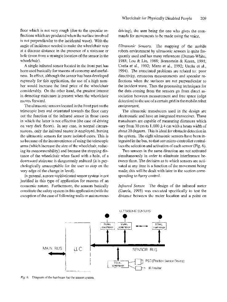
The ultrasonic transducers used in the design are electrostatic and have an integrated transceiver. These transducers are capable of measuring distances which vary from 30 cm to 1,000:t:4 cm with a beam width of about 20 degrees. This is ideal for obstacle detection in the system. The eight ultrasonic sensors have been in- tegrated in the bus, so that one micro-controller central- izes the selection and activation of each sensor (Fig. 6).
Two sensors in the same direction are not activated simultaneously in order to eliminate interference be- tween them. The decision as to which sensors are acti- vated at any time is a function of the movement being made; this will be dealt with later in the section corre- sponding to fuzzy control.
Infrared Senso~ The design of the infrared meter (Garcfa, 1993) was executed specifically to test the distance between the meter location and a point on
MAIN BUS
I
I CONO
I
HONER I
ULTRASONIC SENSORS
I 51GNAL
~NDITIONER
O
II II SENSOR BUS
~ PSD (Position Sensor Device)
J ~'-~' ~ IR Emitter
Fig. 6. Diagram of the hardware for the sensor system.

210 Mazo et al.
Fig. 7. Detection of stairs using infrared sensors.
the floor (approximately one metre in front of the wheelchair).
The detection of a sudden increase in the measure- ment infers the existence of a steep slope (a downward stair or a hole). This type of measurement could not be made with the ultrasonic sensors because of the floor reflections.
The sensor which has been developed allows dis- tances to be measured within a range of 20 cm to 600 cm, with a resolution of :t:2 cm. With this the pres- ence of stairs or differences in levels can be detected easily within a very wide margin of distances from the wheelchair. In effect, considering that the height from the floor at which the sensor (h) is located is 50 cm, as can be seen in Fig. 7, and depending on the angle of inclination (o~) the presence of stairs can be detected at a distance (d) of 100 cm, which is sufficient distance for detaining the wheelchair, even when it is moving at maximum speed. It should be mentioned that the pres- ence of obstacles just in front of the wheelchair can be detected with this sensor (although these will gen- erally have been detected previously by the ultrasonic system).
This sensor has been developed using 960 nm infrared emitter diodes (LED) and a PSD (Position Sensor Device) (Mazo et al., 1993). Measurement of distance is obtained by triangulation, as indicated in Fig. 8, from position x in which the radiation gener- ated by the LED affects the PSD, after being reflected
by the object whose distance has to be measured. Thus, the distance, d, from the object can be easily obtained from a similarity in triangles and is shown by Eq. (1):
x a f a f d =* d = x (1)
where
x: position measured by the PSD.
f : focal distance of the PSD optical system.
a: distance between the IRED and PSD.
d: desired distance.
The optics associated with the PSD and the IRED have been chosen, on the one hand, in order to achieve a sufficiently wide field of vision and, on the other hand, in order to achieve a sufficient range with the infrared beam without any great dispersion.
5 Physical Description and Mechanical Model of the Wheelchair
The wheelchair, which is a commercial model, is made up of a square platform (as shown in Fig. 9) with two freewheeling castors in the front and two fixed inde- pendently controlled drive wheels at the back. This is the rear shaft of the wheelchair, where the actuators are D.C. motors with built-in reduction gears and optical

Wheelchair for Physically Disabled People 211
Fig. 8.
SIGNAL
IRED ], DRPVER Measurement of the distance by triangulation by means of infrared sensors,
SENSOR BUS
Fig. 9.
8
LEFT
470 mm v
FREEWHEELING CASTOR
OPTICAL ENCODERS
RIGHT
MOTOR
DRIVING WHEELS
D = 700 mm U v I
Upper view of the platform of the wheelchair.
(,O r
encoders. These two drive wheels provide the power needed for the displacement of the wheelchair and con- trol of both the speed and the direction, by applying different torques to each. A point to be considered is the distance between the two drive wheels that de- pends on the width of the platform. It is desirable for the two drive wheels to be as far apart as possible, for the following reasons:
- - The static and dynamic stability of the wheelchair are improved.
- - The influence of the encoder resolution on the di- rection error of the wheelchair is decreased.
- - During straight-line motion, mechanical and elec- trical disturbances will cause the motors to run at different angular speeds, resulting in a temporarily curved path. It is known by using trigonometry that the radius of the curved path is directly pro- portional to the distance between the drive wheels.
In the wheelchair used in this design, the distance between the two drive wheels is 700 mm. The distance

212 Mazo et al.
between the drive wheel shaft and the castor shaft is 500 mm.
Several control strategies have been developed in the control systems, varying from classic to optimal and stochastic control techniques. All of them use a mathematic model system for control and to evaluate the chosen strategy. Therefore a model of the system is necessary first so that any control strategy can be applied.
The wheelchair will be considered as a rigid body, disregarding the mass of the four wheels and the rotors of the electric motors. Then, as the wheelchair's motion is planar, three degrees of freedom can be considered.
From basic kinetics, it can be observed that the in- stantaneous rotation centre can be found in the geo- metrical intersection of the shaft of each wheel. This instantaneous rotation centre can first be determined by the amount of each speed vector of the drive wheels. Thus, for a straight path and smooth, undisturbed mo- tion, the instantaneous rotation centre is at infinity. On the other hand, the smallest circular path is found in the middle point between the two drive wheels (where there are equal and opposed torques on the drive wheels). Also the freewheel position is found by taking the angle which represents the lowest opposition to the motion.
In conclusion, it can be seen that: (A) the minimum curvature radius of the centre of the mass agrees with the distance between the drive wheel shaft and the cen- tre of the mass; (B) paths that correspond to undisturbed freewheel motion have continuous curvature.
For the motion equations for the wheelchair, a linear mechanical model (Dupourque, 1990) has been used which gave the following equations:
co'r = APl + BFr
co; = APr + bPl (2)
with
1 D 2
a = 2MR------ ~ + .SR2J (3)
1 D 2 B - (4)
2 M R 2 8RgJ
where
R: Radius of drive wheel. D: Distance between drive wheels,
cot : Angular speed of right drive wheel (col r = d c o r / d t )
cot: Angular speed of left drive wheel (col = clcodclt)
Ft: Torque applied to the left drive wheel. I" r: Torque applied to the right drive wheel. J: Moment of inertia of the system.
M: Mass of the system.
The relations between the translation (V) and rota- tion (f2) speeds of the wheelchair in terms of cot and coz a r e :
R V = 7(col + cot)
R f2 = ~(cot + co,) (5)
therefore, the direct and inverse models come from:
(6) k a J -g :2 cot
(7)
6 Sys tem Control
Figure 10 shows the general configuration of the sys- tem control. The low-level control is the control loop of each drive wheel (cot and cot are the angular speeds of the right and left wheels respectively). In our application the speed-loop is closed using optical encoders, in the centre of the motor shafts, and a digi- tal PID-controller. The chair-level control establishes the control loops for the wheelchair angular (f2) and displacement (V) speeds. The sensed forward solution and the activated inverse solutions are used to estab- lish the control loops for the wheelchair angular and displacement speeds.
When the sensor system detects an obstacle it acts on the lower levels to adapt the speed of the wheelchair to the environment. The command introduced by the user is considered as being the highest level, so that, in normal operating conditions the rest of the sub-systems are subject to the commands of the user. The only ex- ception is produced when the user gives a command and the sensor system detects the persistence of an im- minent danger (for safety reasons and given the type of user, movement forward is not permitted, for example, when the existence of a down staircase has just been detected). The user command may be given by means

Wheelchair for Physically Disabled People 213
ENCODERS
ULTRASONICS
INFRAREDS
ULTRASONICS
CHAIR KINEMATIC & DINAMIC
LOW LEVEL AND CHAIR-LEVEL
CONTROL
COLLISION AVOIDANCE
HUMAN VOICE COMMANDS
JOYSTICK
Fig. 10. Global control diagram.
< )
DRIVE MOTORS
of a joystick or a voice recognition system. This is pro- cessed in order to send the speed instructions (t2 and V) to the controller, at chair level.
Low Level and Chair Level Controls. These controls are as shown in Fig. 11 in which Vref and ~'~ref a r e the desired speeds of the wheelchair in translation and ro- tation respectively. The values of Vr~f and ~'~ref c a n be given by:
A) The Joystick. B) Voice commands. C) Ultrasonic and infrared sensors (fuzzy control).
The controllers for the V and f2 and the COr and ~ol speeds are digital PID-controllers (Dote, 1990). The angular speeds of the motors are taken through two optical encoders in the centre of the motor shafts. These speeds are fed back to two specific integrated circuits (LM628) to implement a digital PID con- trol. The 8-bit code coming from the LM628 gener- ates the power stage excitation signal. This line is forced to provide a 50% duty cycle PWM signal when the data equals zero. An 87C51FB micro-controller controls and programmes the LM628. This micro- controller receives orders from the serial net; the orders
come from upper control levels (recognition and sen- sor board). With this information, the micro-controller generates the necessary commands and sends them to the LM628 and monitors and detects fault and error conditions. These errors activate the protection cir- cuit through an overload current or a shutdown voltage (Mazo et al., 1994a).
The IC LM628 works in the control mode posi- tion, although by constantly changing its set point it is possible to obtain speed control. Control is based on the discrete PID algorithm (equal to (8)) and it allows the limit of the integral term to be changed. It re- duces the amount of error, when the system becomes saturated.
u(n) = Kpe(n) + K1 ~ e(N) N=0
+ Ko(e(n') - e(n' - 1)) (8)
where u(n) is the control signal at the instant n, e(n) is the error signal, n' shows the derivative sampling times and Kp, Kr, and KD are the programmable con- stants of the PID. The sampling instants of the pro- portional and integral terms are not programmable and come from the clock period. The derivative period is

214 Mazo et al.
I SENSORS }
lr
INERTIA)
I FUZZY CONTROL I
li. v - i l -O~l ~ _ r~.,.] - -
CO~I~OL 8~C%N
ENCODERS, ]
Fig. 11. Low level control.
programmable, from a lower value to another equal to the other two terms. This function is useful when adapt- ing the system to the load and time constant associated with it. At low speeds, the sampling intervals are large because they are sufficient and reduce the sensitivity to sudden error changes.
The PID constants have been adjusted in the test stage to obtain a great stability margin without vari- ations. Thus the desired speed is obtained even with great load changes and the appearance of great changes in levels.
Each power unit is made up of a full H bridge of four MOSFET transistors (Julliere et al., 1979; Harris Semiconductors, 1992), with their excitation circuits that make speed control and turning in any direction by Pulse Width Modulation (PWM) possible (Mazo et al., 1994a).
Control by Voice Commands. A set of only nine voice commands has been included to simplify the use of the wheelchair. These control words (commands) have to be chosen by the user and recorded on a memory card. Each command has an associated function: "Stop", "Forward", "Back", "Left", "Right", "Plus", "Minus", "Password" and "Track".
These commands work as shown in Fig. 12. The wheelchair has nine states: stopped, going forwards or backwards, turning itself round, to the right or to the left and going forwards or backwards turning simultaneously.
Starting from a rest position (V = 0, S2 = 0) com- mands such as "Forward", "Back", "Left", "Right" give V or S2 speed a predetermined initial value,
positive or negative, according to the case. Then the "plus" and "minus" commands increase or decrease speed up to certain pre-arranged limits.
The "Password" command, which does not appear in Fig. 12, when pronounced once stops the recogni- tion process and the movement of the wheelchair it- self. This enables the user to have a conversation in which those words, having a control function assigned, may appear with the only exception of the control word "Password". When it is pronounced for a second time, it returns to the previous control.
Another command is "Track", which allows switch- ing between the "Voice Control" and the "Autonomous Control" modes.
Fuzzy Control of the Sensor System. Supposing that the wheelchair is moved in an environment which is, in principle, free, with all the sensors activated, and an obstacle is detected, various solutions are possible to avoid collision: go round the obstacle, therefore changing the path selected by the user, or stopping the wheelchair.
If the obstacles are moving (for example, people), in the majority of cases it is not necessary to stop the wheelchair, it is sufficient to reduce speed until the ob- stacle disappears from the path of the chair, an action which, on the other hand, is less sudden than stopping the chair.
On the basis of this, the choice has been made to reduce the speed of the wheelchair in the presence of obstacles, stopping wherever it is necessary, re- establishing the former situation once the obstacle has disappeared.
Wheelchair for Physically Disabled People 215
"S": "F': "LR': I I ....
Fig. 12. States of the wheelchair in terms of the voice commands.
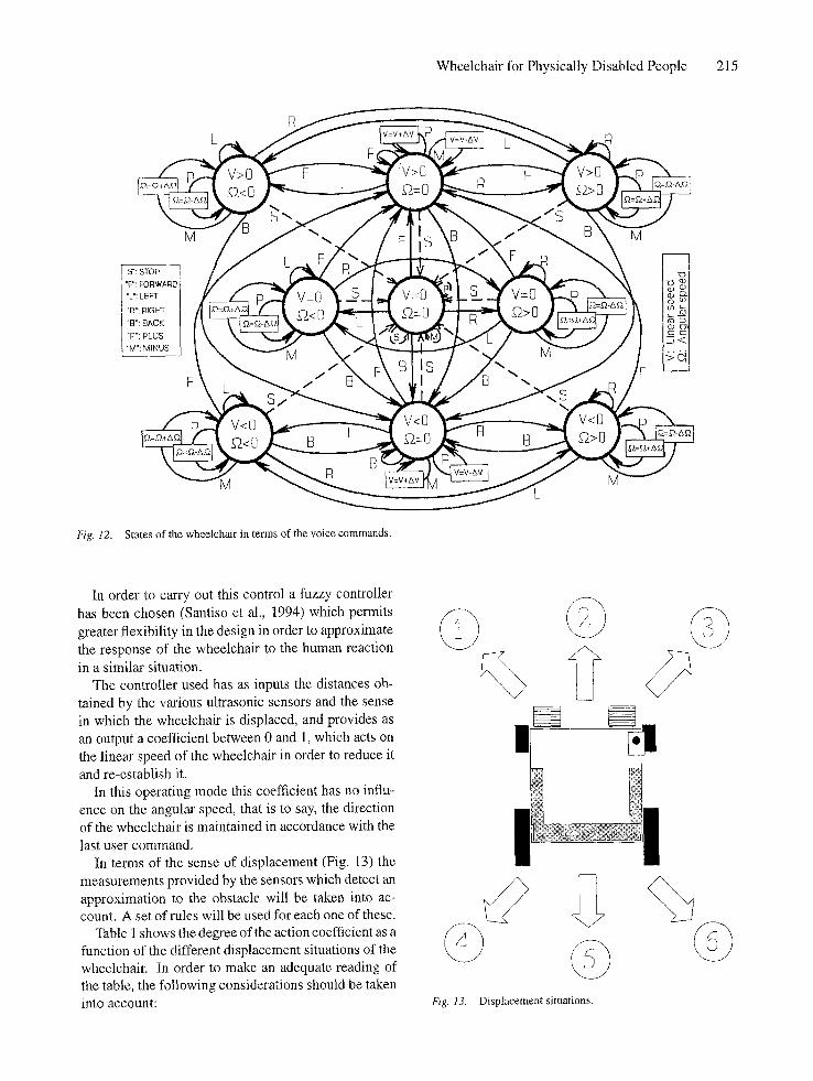
In order to carry out this control a fuzzy controller has been chosen (Santiso et al., 1994) which permits greater flexibility in the design in order to approximate the response of the wheelchair to the human reaction in a similar situation.
The controller used has as inputs the distances ob- tained by the various ultrasonic sensors and the sense in which the wheelchair is displaced, and provides as an output a coefficient between 0 and 1, which acts on the linear speed of the wheelchair in order to reduce it and re-establish it.
In this operating mode this coefficient has no influ- ence on the angular speed, that is to say, the direction of the wheelchair is maintained in accordance with the last user command.
In terms of the sense of displacement (Fig. 13) the measurements provided by the sensors which detect an approximation to the obstacle will be taken into ac- count. A set of rules will be used for each one of these.
Table 1 shows the degree of the action coefficient as a function of the different displacement situations of the wheelchair. In order to make an adequate reading of the table, the following considerations should be taken into account:
© © © Fig. 13. Displacement situations.

216 Mazo et al.
Table 1. Action coefficients according to various cases.
CASE1 [ UF1, UF2 ]
EP EG G,G G,P
P ! CP CP CP CP
G CP CP CG CG
CASE2 I UF1 I
P G
- ~ P CP CP
G CP CG
CASE 3 UF1, UF2
P,P P,G G,G G,P
-~ P CP CP CP CP
G CP CG CG CP
CASE 5 [ UB
P G
CP CG
CASE 4 [ UL2, UR1
EP RG G,G G,P
-~ P CP CP CP CP
G CP CG CG CP
CASE6 UR2, UL1 I
RP RG G,G G,P
-~ P CP CP CP CP
G CP CG CG CP
a) UF1, UF2, UL1, UL2, UR1, UR2, UB are the dis- tances measured by the different sensors, taking into account the location of these (see Fig. 5).
b) P and G are the relations belonging to a small or large distance of the sensor measurement.
c) CP and CG is the degree of the action coefficient as a function of the distances measured. CP indicates the small coefficient and CG the large.
The six possible cases of movement are shown in the Table 1 (as shown in Fig. 13), only reflecting the measurements obtained from the activated sensors according to the type of displacement being made by the wheelchair. This is so because it is from the mea- surement of the activated sensors that the action co- efficient is obtained. For example, in case 3: "If the measurement of UR1 is large (G) and the measurement of UF1 is small (P) and the measurement of UF2 is large (G), then the action coefficient is large (CG)".
Fuzzification was carried out using a pertinency function for the frontal distance and another for the lateral and rear distances. The possession functions may be observed in Fig. 14a.
The reason for using higher values in the perti- nency function for the frontal distances i s tha t in this
movement sense more rapid displacements are pro- duced than in the rest of the manoeuvres. The output function is shown in Fig. 14b.
In the case of the ultrasonic sensors directed towards the floor or the infrared sensor detecting a hole, the controller will give an output coefficient of 0, which will cause the immediate stopping of the wheelchair. This rule prevails over all others if the forward move- ment sense is towards the hole that has been detected. Figure 15 shows the block diagram of the complete fuzzy controller.
Autonomous Control. The "AUTONOMOUS" con- trol mode is used to ensure that the wheelchair follows walls at a certain distance from same. Figure 16a shows how switching from the "VOICE" control mode to the "AUTONOMOUS" control mode is achieved by means of voice commands. As may be observed, this switch- ing of the control mode is achieved by pronouncing the word "TRACK", followed by the word "LEFT" or "RIGHT" depending on whether the wall situated to the left or the right has to be followed.
The voice commands "MORE" and "LESS" are only effective in the "AUTONOMOUS" mode and permit

Wheelchair for Physically Disabled People 217
Front or Back Distances Side Distances
Shor_i_t ~(D k Lon_ g Sh Long
60 300 D (cm) 40 100 D (cm) O 1 L1hs~r Speed
(a) (b)
Fig. 14. (a) Pertenency functions, (b) Action functions.
Fig. 15.
i
DISTANCE M E S U R E M E N T S OF DIFFERENT SENSORS [
I - U L T R A S O N I C S E N S O R S A R O U N D T H E C H A I R
- I N F R A R E D S E N S O R
.................................................................................................................................................. ........................... V ................................................................................................................................
I REDUCTION SPEED [ I MEASUREMENT CONTROL
, ESTO ATIONI i ,
IMMINENT
COLLISION HOLE DETECTED
STOP CHAIR
SPEED
FUZZY CONTROL
Block diagram of the fuzzy controller.
the linear speed of the wheelchair to be modified, although subject to the information collected by the active sensors.
Taking into account the diagram in Fig. 16b for the case of following the right wall, the new rules added to the fuzzy controller are obtained from the distances measured by the senors UF1 (dF~), UR1 (d m) and UR2 (dR2). The objective is for the robot to be parallel to the wall. A fuzzy rule is added in this operating mode which acts on the angular speed of the wheelchair. The angle of orientation of the robot, with respect to the wall to be followed, 0, is obtained using' the following
equation:
0 = tag -1 dR2 - - dm (9) s
The distance for following the wall is adjusted to the average of the two measurements of the correspond- ing side sensors at the time that the order "RIGHT" or "LEFT" is given in this mode. This has to be taken into account by the user when selecting this dis- tance. This mode has been conceived for guiding a wheelchair along relatively long passages, without the user having to correct the direction of the wheelchair. It

218 Mazo et al.
~~PLUS~mS
a)
Fig. 16. (a) Change of operating mode, (b) Variables used in following walls.
b)
e [
i
has not been considered for situations where the walls have recesses, doors, etc. In these cases the user will have to take over control again and give orders for the wheelchair to move in a sense in which the sensors do not detect any situation of collision or imminent falling. In the latter cases, for safety reasons, movement of the wheelchair is not permitted.
7 Speech Recognition
Figure 17 shows a block diagram of the speech recog- nition used (Furui, 1989). The Analogue Proces- sor consists of a preamplifier, a bandpass filter and
a compressor to ensure that the signal from the mi- crophone (for this application a single directional one) is noise free and has a suitable level. This improves the recognition performance considerably when deal- ing with noisy environments or any great changes in intensity when pronouncing words.
The signal is then introduced into a 7-channel filter bank for frequency analysis. Each filter bank channel consists of a supplementary low pass filter (LPF), a band pass filter (BPF), a rectifier and a smoothed low pass filter. The output from the smoothing LPF repre- sents an average amplitude time series of waveforms in a passband frequency region determined individually for each filter channel. A single analogue-to-digital
ANALOG ~ROCESSOR
Pre-amptifier +
;and Pass Filtel + Compressor
FILTER BANK
Low Pa..l~s Filter I /Band P~ss FiIter | Rectifier
i
MEMORY I CARD
(Pattern}
I
AID I~, IPROCESSOR o , ,
I
l CENTRAL
I~ PROCESSOR
Fig. 17. Block diagram of the voice recognition system.

converter (ADC) digitizes the seven outputs of the smoothed LPFs from a multiplexer one by one. The ADC digitizes each channel every 20 ms. The input- output digitizing characteristic in the ADC shows non- linearity with the 8-bit compressed output.
Reference patterns for vocabulary to be recognized must be stored in a memory before recognition. This function is carried out by a personal memory board capable of recording up to 10 different users. The refer- ence pattern for each word is made by analyzing three utterances.
The Digital Processor (Fig. 17) compares the input voice features with vocabulary reference patterns pre- viously stored in a S-RAM. This block calculates the similarity between the input voice data and the refer- ence patterns for each word. The recognition results, showing the most candidates possible for input words, are transferred to a host computer.
8 Results
After three years of research and development, the au- thors have managed to construct a prototype wheelchair (UMIDAM) which can be guided by people suffering great physical incapacity. Compared with other proto- types developed, this chair has the advantage of includ- ing a control system for voice commands together with a multi-sensor system which allows obstacles and im- portant changes of level in floors to be detected (such as downward staircases). All this allows people to move around in an easy manner (the voice commands used are few) and a safe one (thanks to the sensor support), even in environments where there are elements which could put these movements at risk.
The design of all the systems has been carried out taking the different environments in which the wheelchair has to move into account and special at- tention has been paid to reliability, cost, power con- sumption, the possibility of making future additions, size and the possibility of adaptation to the chassis of commercial wheelchairs. The results obtained show a prototype which responds to a large degree to the re- quirements of people who need a wheelchair in order to be able to move around. It only requires the help of a person to configure the system initially. Further- more, function both in interior and exterior spaces is guaranteed.
Numerous tests have been carried out on the wheelchair prototype at present in operation. These tests were carried out with different people suffering
Wheelchair for Physically Disabled People 219
from various types of incapacity, some of them potential users of a wheelchair with these character- istics. All these tests permitted modifications to be made in the original project so that the final product could be adapted, as far as possible, to the need for mobility of this type of user.
The tests were carried out in interior and exterior spaces. Interior tests were made in passages, rooms, areas with different types of flooring (greater or lesser roughness, different colour types, carpeted and tiled floors, etc.), glass wails, the presence of staircases and ramps, different types of lighting (natural and artifi- cial), etc. In exterior spaces, tests were carried out on surfaces made with different types of materials, dif- ferent slope values (up to 18%) and different climatic conditions (sunny days and cloudy days, different tem- peratures and degrees of humidity, etc.).
The most important features of the UMIDAM pro- totype are as follows:
1) As dynamic characteristics, the control system gives a high accuracy even in position, displacement and turning even with changing the load and/or surface of the ground. The performance of the System has great independence with regard to the working con- ditions.
The wheelchair has been tested with and without a load including different phases of motion: accel- eration, constant speed and deceleration. The po- sition error in the wheelchair in these experiments was less than 100 mm after travelling a distance of 10 m following a straight line. This shows that any inaccuracies in the position were caused by control- independent effects, some of which are as follows:
a) The difficulty in obtaining rubber wheels with exactly the same diameter. In addition un- equally distributed loads slightly compress one wheel more than the other, thus changing the diameter. Wheels with different diameters cause the wheelchair to travel along an arc, rather than along a straight line, even if the motors are run- ning at exactly equal speeds.
b) There is a contact area, rather than a contact point, between the wheel and the floor. This fact causes uncertainty over the effective dis- tance between the drive wheels, creating inac- curacies when turning.
c) The drive wheel can slide so the angular speeds obtained from the encoders do not allow the real displacement of the chair to be calculated.

220 Mazo et aL
2) The sensor system guarantees the detection of ob- stacles and stairs independently, to a large degree, of the characteristics of the environment in which the wheelchair is moving.
Thus, the ultrasonic sensor system, located around the chair, permits any obstacles in its en- vironment to be detected. The characteristics of the sensors, the number and orientation of these guar- antee the detection of obstacles which may be more frequently present. The problems of momentary in- exactitudes in the measurements (through specular reflections, absorption, etc.) are minimized with the type of fuzzy control used.
For the detection of stairs and pronounced differ- ences in level an infrared sensor has been designed and installed. The characteristics of this sensor and its location allow the presence of a staircase at a horizontal distance to be detected, a measurement taken from the support point of the front wheels, which may be adjusted in a range of approximately 0.2 to 5 metres. In the UMIDAM this distance has been adjusted to 1 metre. It is clear that this safety distance is sufficient for stopping the wheelchair in normal speed and weight conditions and roughness of the floor.
The detection of staircases by means of the in- flared sensor has been tested numerous times and in different situations of wheelchair speed, colour and roughness of the floor, environmental light, etc., results being obtained which guarantee a high level of safety.
Only the problem (which was known previously) of loss of measurement on floors with a very dark colour was detected in the tests carried out. Thus it was proved that the characteristics of wave length and power of the infrared sensor used did not permit a reflected signal to be obtained in those cases where the floor was of a very dark colour (black). This type of floor caused the wheelchair to stop even when stairs or pronounced changes in level did not exist.
The use of a laser diode which would allow greater emitter power was considered at first in or- der to avoid this problem, but the additional cost implied made it necessary to consider a more eco- nomic solution which was even more important as the circumstance of a very dark floor is not very frequent. The solution adopted consisted of using two ultrasonic sensors, orientated in such a way that their acoustic axis was perpendicular to the floor, in the front part and with the pos- sibility of locating them in a horizontal position
3)
4)
300 mm in front of the support point of the front wheels.
If the user of the chair does not anticipate mov- ing in environments with a very dark floor, these sensors are not activated and can remain with- drawn. These sensors have been adjusted so that when they detect a difference in height which exceeds a pre-determined threshold (in this case 70 mm) in two consecutive measurements, the wheelchair is detained. It should also be mentioned that, when these two ultrasonic sensors begin to op- erate, an adjustment of the measurement of the ini- tial height is carried out which logically depends basically on the weight and pressure conditions of the wheels.
In those cases where floors with grids exist, the infrared system can detect the presence of holes and thus stop the chair. This type of surface must be avoided by the user. A possible solution, not included in this system for safety reasons, consists of permitting the user to de-activate the infrared system by means of a voice command when he/she wishes to move over a floor with a grid. If the sensor system detects any circumstance which could suppose a risk to the user (collision with ob- stacles, falling down stairs, etc.), the wheelchair is detained ignoring those voice commands which in- dicate the risk being maintained. This solution has the advantage of guaranteeing the safety of the user, but has the disadvantage of the fact that if the sensor system detects a danger situation and the user does not consider it as such, certain movements cannot be made although the user may wish it.
Obviously, a solution where the voice commands have priority over the sensor system would also fa- cilitate the solution of some of the problems pre- sented by very dark floors or grids, since total con- trol can be assumed by the user. The electronic system has been designed to permit the selection of different maximum driving speeds. This selection is made by means of switches located on the motor control board (for off-line configura- tion). In this way users of the wheelchair may be limited to only moving at the maximum speeds pre- viously established and which may be conditioned by the characteristics of the environment in which the chair has to move or by the requirements of the user himself. The maximum speed that a UMIDAM can achieve has been limited to 3 m/sec. Obviously the reliability of the sensor systems decreases with the speed, which has to be controlled by the user.

5) The wheelchair has an interface, made up of a dis- play and four push buttons which allow the system to be configured initially. This configuration only has to be made once as it is memorized. The con- figuration supposes: recording the voice commands which each user wishes to use for making the vari- ous movements (if these are not previously stored) and activating/de-activating the different ultrasonic and infrared sensors.
The display shows the user selected when the power is connected (there may be up to 10 possi- ble users of the same board), guides the user in the steps that he has to follow to make the configura- tion, warns of possible failures in voice recognition or sensors, danger situations (presence of obsta- cles, staircases, etc.) and any of the more frequent faults which may occur in the hardware (absence of boards, high current for the motors, absence of memory-card, etc.).
At the first stages, the design of an interface sys- tem was considered including a voice synthesizer instead of the display, but this idea was rejected as not being very attractive for the user. The connec- tion and configuration of the system by voice com- mands was also considered but was also rejected because the possible users of the wheelchair, given their great incapacity, would almost certainly re- quire the initial help of another person. Therefore, the potential users of the wheelchair need the help of another person to put the wheelchair into oper- ation and to make the initial configuration (when necessary).
If the guiding of the wheelchair is carried out by means of a joystick, selection must be made with a switch provided for same, before connecting the power.
6) The electronic system developed permits adapta- tion to a large number of commercial wheelchairs very easily. The cost supposed by this adaptation is relatively small in comparison with the cost of a commercial wheelchair controlled only by means of a joystick. If the reference is to the Spanish mar- ket, this additional cost may be estimated at around 35%. Emphasis should also be placed on the small volume of the electronic system and its low con- sumption.
7) The voice recognition system assures a success rate in the order of 96% for a user with some train- ing. It has been specially designed to maintain this success rate in places where there is a fairly high level of environmental noise (above that which
Wheelchair for Physically Disabled People 221
is normal in environments where the movement of these wheelchairs is frequent). Even so, if the sys- tem fails to recognise two voice commands consec- utively, the wheelchair automatically stops and has to be started again by the user.
The wheelchair has a memorycard which, among other things, allows the user himself to record up to ten types of voice command patterns or the wheelchair to be used by different users with the same card.
9 Future Developments
Work is at present being carried out on the incorpo- ration of a new interface so that the user can give or- ders on guiding based on eye movement. The part of the system that has already been developed is be- ing tested with fairly satisfactory results. This will provide an answer to the needs of people who are severely handicapped and, furthermore, the hardware for the treatment of images may be used to reinforce the autonomous guiding of the wheelchair (including passing through doorways, avoiding obstacles, etc.). However, the cost of the system will be considerably increased.
Acknowledgments
The authors wish to express their gratitude to the com- pany CIBERVEU, S.A. (ONCE Group) for all the sup- port that it has given to the development and refining of this project. Thanks are also due to the CICYT (Spanish Inter-ministerial Commission for Science and Technology) for the aid received, via the ROB90-0992- C03-01 and TAP94-0656-C03-01 projects, some of the results of which have been translated to the UMIDAM project.
Notes
1. Intelligent Mobile Unit for the Aid of the Disabled.
2. The ONCE Foundation (National Organization for the Blind in Spain) is widely known in Spain through its efforts to help disabled people, above all with programmes and activities for social integration.

222 M a z o et al.
References
Borenstein, J. and Koren, Y. 1985. A Mobile Platform for Nurs- ing Robots. IEEE Transactions on Industrial Electronics, 32(2): 158-165.
Borenstein, J. and Koren, Y. 1991. The vector field histogram-- fast obstacle avoidance for mobile robots, IEEE Transactions on Robotics and Automation, 7(3):278-288.
Bradley, M. Inc. 1980. Big Track. Robotics Age, 2(1):172-173. Crowley, J.L. 1987. Coordination of Action and Perception in a
Surveillance Robot, IEEE EXPERT. Dote, Y. 1990. Servo Motor and Motion Control Using Digital Signal
Processors. Prentice Hall. Dupourque, V. 1990. Techniques Classiques de Commande des
Robots Mobiles. En Seminaire Les Robots Mobiles. La D6fense. Paris.
Durrant-Whyte, H.E 1988. Integration, Coordination and Control of Multi-sensor Robot Systems. Kluwer Academic Pub.
Eden, Y., Engel, B.A., and Miles, G.E. 1993. Intelligent Control System Simulation of an Agricultural Robot. Journal of Intelligent and Robotic Systems, 8(2):267-284.
Furni, S. 1989. Digital Speech Processing, Synthesis and Recogni- tion. Marcel Dekker.
Garcfa, R. 1993. Contribuci6n a un Sistema Integral de Navegaci6n, de Robots m6viles multisensoriales, mediante infrarrojos. Ph.D. U.P.B. Madrid.
Gelin, R., Detriche, J.M., Lambert, J.P., and Malblanc, E 1993. The COACH Project. Proceedings oflCAR'93 Piscataway, N.J., pp. 547-552.
Goto, Y. and Stentz, A. 1987. Mobile Robot Navigation: The CMU System. IEEE EXPERT.
Grant, W.H. and White, R.L. 1994. The Tim Man Project. Proceed- ings of the CIRF'94. Dallas.
Harris Semiconductor 1992. Intelligent Power 1Cs. Jin, S., Kimura, I., and Watanabe, K. 1993. Control of Servomo-
tors for Carry Hospital Robots. Journal of Intelligent and Robotic Systems, 7(3):353-359.
Julliere, N., Merce, L., and Perrichot, H. 1979. An H-type Switching Mode Power Supply for DC Servo Motors. Int. J. of Electronics, 24(5):507-512.
Leifer, L. 1981. Rehabilitative Robots. Robotics Age, 3(3):000-000. Lou, R.C. and Lin, M.H. 1988. Robot Multi-Sensor Fusion and Inte-
gration: Optimum Estimation O f Fused Sensor Data. IEEE Trans. on Robotics and Automation, RA-2 (3): 1076-1081.
Maravall, D. and Mazo, M. 1990. Guidance of an Autonomous Ve- hicle by Visual Feedback. Cybernetics and Systems: An Interna- tional Journal, 21:257-266.
Mazo, M., Garcfa, R., Revenga, P., Urefia, J., and Santiso, E. 1992. Mobile Robot with Multi-Sensor Integration. In Symposium on Intelligent Components and lnstruments fbr Control Application. (SICICA'92), M~daga, Spain.
Mazo, M., Urefia, J., Garc/a, J.J., Rodrfguez, EJ., Garcfa, J.C., San- tiso, E., and Revenga, E 1994a. Control de Motores de CC de Media Potencia: Aplicaci6n al Guiado de una Unidad M6vil (1 and 2). Rev. Espa~ola de Electr(Snica. pp. 56-56 (December 1993) and pp. 54-58 (January 1994).
Mazo, M., Rodrfguez, F.J., Lfizaro, J.L., Urefia, J., Garcia, J.C., Santiso, E., Revenga, R, and Garcia, J.J. 1994b. Intelligent Elec- tronic Control for a Wheelchair Guided by Voice Commands and External Sensors. AIRTC'94. pp. 385-390. Valencia (Spain).
Mazo, M., Urefia, J., Garcfa, J.J., Rodrfguez, EJ., Garcfa, J.C.,
Santiso, E., and Revenga, E 1993. Detectores Sensibles a la Posici6n: Funcionamiento, Estructura y Aplicaciones. Rev. Eu- rofach Electrdnica. pp. 62-66.
McAlister, D. 1980. Superkim Meets ET-2. Robotics Age. 2(3): 186-195.
Meng, M., and Kak, A.C. 1993. Mobile Robot Navigation using Neural Networks and Non-Metrical Environment Models. IEEE Control Systems, pp. 30-39.
Miller, D. and Grant, E. Design & Testing of a Low Cost Robotic Wheelchair Prototype. Proceedings of CIRFSS'94.
Moravec, H.P. (Ed.) 1985. Autonomous Mobile Robot Annual Re- port. Robotics Institute Technical Report No. CMU-RI-TR-86-1, Carnegie Mellon University, Pittsburgh, PA.
Sabbe, J.J. 1993. Project: SKIL-Bijsturingssysteem, SKILNV. Gent. Belgium.
Santiso, E., Mazo, M., Serra, C., Garcia, J.J., and Rodrfguez, t~J. 1994 Aplicaci6n de algoritmos borrosos al guiado de un robot m6vil con visi6n artificial. Fuzzy '94. pp. 247-251, Blanes (Girona, Spain).
Sitherama Iyengar, S. and Elfos, A. 1991. Autonomous Mobile Robots: Control, Planning and Architecture. IEEE Computers Society Press. Los Angeles, California.
Sitherama Iyengar, S. and Elfos, A. 1991. Autonomous Mobile Robots: Perception, Mapping and Navigation. IEEE Computers Society Press. Los Angeles, California.
Urefia, J. 1992. Percepci6n de entornos y guiado del Robot m6vil me- diante ultrasonidos. P E C.E. Z S. Ingenieros de Telecomunicaci6n. Madrid.
Urefia, J., Mazo, M., Garcfa, J.J., L~izaro, J.L., Revenga, P.A., Garc/a, J.C., Rodrfguez, F.J., and Santiso, E. 1995. Sensores de ultra- sonidos e infrarrojos usados en la detecci6n de obstficulos e irreg- ularidades del suelo para aplicaciones de robots m6viles. 111 Jor- nadas de Tecnologfa Electrdnica (Meetings on Electronic Tech- nology). Gran Canaria (Spain), pp, 153-158.
Urefia, J., Mazo, M., and Rodrfguez, F.J. 1994. Captaci6n de En- tornos en Robot M6vil mediante Ultrasonidos (1 and 2). Rev. Espagola de Electrdnica. pp. 46-53 (April 1994), pp. 64-68 (May 1994).
Watanabe, Y. and Yuta, S. 1990. Position estimation of mobile robots with internal and external sensors using the uncertain evolution technique. IEEE lnt. Conf. on Robotics and Automation.
Dr. Manuel Mazo obtained his Electronic Engineering and Telecom- munications Engineering degrees and his Doctorate in Telecommu- nications Engineering from the Polytechnic University of Madrid (Spain) in 1976, 1982 and 1988 respectively. He has been a Lecturer in the Technical School in Alcal(t since 1976. At the present time

Wheelchair for Physically Disabled People 223
he is the Director of the Electronics Department at the University of Alcal~i de Henares. Mr. Mazo has carried out considerable research work on Artificial Vision and Multi-sensor Integration applied to Mobile Robots. His present areas of interest are Mobile Robots, Artificial Vision and Speech recognition.
Francisco J. Rodriguez obtained Electronic Engineering and Telecommunications Engineering degrees from the Polytechnic Uni- versity of Madrid, Spain, in 1985 and 1990 respectively. He has been lecturing in the Electronics Department of the University of Alcahide Henares since 1986. He is currently working for his Ph.D. His area of interest is Artificial Vision applied to Mobile Roots.
Madrid, Spain, in 1985 and 1992, respectively. He has been a lec- turer in the Electronics Department of the University of Alcalfi since 1986, also working on several projects related to Mobile Robots. He is currently working for his Ph.D. His area of research interest is in the field of Multi-sensor Integration.
Juan C. Garcfa obtained his Electronic Engineering and Telecom- munications Engineering degrees from the Polytechnic University of Madrid, Spain, in 1987 and 1992, respectively. After several years in the private electronics industry, he has been a lecturer in the Electronics Department of the University of Alcal since 1985. He is currently working for his Ph.D. His areas of interest are Robotics and Fuzzy Logic Controllers.
Jos6 L. L~izaro obtained his Electronic Engineering and Telecom- munications Engineering degrees from the Polytechnic University of Madrid, Spain, in 1984 and 1992, respectively. He has been a lec- turer in the Electronics Department of the University of Alcalfi since 1986. He is currently working for his Ph.D. His area of research interest is Speech Recognition.
Jestis Urefia obtained his Electronic Engineering and Telecommu- nications Engineering degrees from the Polytechnic University of
Enrique Santiso obtained his Electronic Engineering degree from the Polytechnic University of Alcal~ide Henares, Spain, in 1989. He is alecturer in the Electronics Department of the University of AlcalL His area of interest is Fuzzy Logic Controllers.
Pedro Revenga obtained his Electronic Engineering degree from the Polytechnic University of Alcalzi de Henares, Spain, in 1989. He is a lecturer in the Electronics Department of the University of Alcalfi. His present research interests lie in the fields of Mobile Robots and Multi-sensor Integration.

224 Mazo et al.
J. Jesfis Garcia obtained his Electronic Engineering degree from the Polytechnic University of Alcal~ de Henares, Spain, in 1992. He is a lecturer in the Electronics Department of the University of Alcalfi. His main area of interest is Digital Control.