Wheel Load Scales WL 101 Operating Instructions Contents€¦ · Wheel Load Scales WL 101 Operating...
16
Wheel Load Scales WL 101 Operating Instructions Exhibit 2 - Wheel Load Scales WL101 Operators Manual
Transcript of Wheel Load Scales WL 101 Operating Instructions Contents€¦ · Wheel Load Scales WL 101 Operating...
Wheel Load Scales WL 101
Operating Instructions ContentsPage
1. Technical details 1
2. Construction and Function 2
3. Operating instructions
4. Sources of errors 4
5. Test instructions 5
Appendix 7
2
Exhibit 2 - Wheel Load Scales WL101 Operators Manual

Wheel Load Scales WL 101
Operating Instructions
Contents Page 1. Technical details 1 2. Construction and Function 2 3. Operating instructions 4. Sources of errors 4 5. Test instructions 5 Appendix 7
2
Exhibit 2 - Wheel Load Scales WL101 Operators Manual

1
1. Technical details Range 0...20 000 lb Scale division 50 lb Accuracy NIST H44, Class IIII Acceptance tolerance ± 50 lb (0-2500 lb) ± 100 lb (2501-10000 lb) ± 150 lb (10001-20000 lb) Maintenance tolerance ± 100 lb (0-2500 lb) ± 200 lb (2501-10000 lb) ± 300 lb (10001-20000 lb) Temperature range operation 0... 120°F storage -20...140°F Dimensions height of platform 0.67 in length of platform 28.5 in width of platform 15.5” Active weighing surface length 26 in width 15 in Maximum permissible load per area 170 lb/in2
Weight 35 lb Construction Aluminum, watertight
2
2. Construction and Function
The Wheel Load Scale Type WL 101 is a portable flat weigher which is specially designed for the fast determination of the wheel load, the axle load and, as well the total weight of vehicles.
It consists of a platform for the weight registration and of a laterally fixed indicator. This platform contains a grating of measuring tubes which are connected mutually and with the indicator. They are filled with a non freezing liquid and are hermetically sealed. The grating is fixed between two metal plates.
The liquid displaced from the elastic measuring tubes produces a deflection proportional to the total load in the bellow of the indicator. As a consequence the indicator can be directly scaled in units of weight.
To eliminate the effect of the thermal expansion of the liquid, a second hydraulic system is installed with exactly the same volume. It acts on a second bellow. A system of levers subtracts the temperature related deflections of the two bellows from each other, thus making the reading independent of the temperature changes.
The changes of the sensitivity of the measuring tubes are compensated by a temperature dependent transmission ratio, employing a bimetallic element in the indicator mechanism.
3. Operating instructions 3.1 Requirements for weighing site selection 3.1.1 The gradient of the weighing site should not exceed 5% in any
direction. See appendix A1 on page #7 for detailed information of affects on the weights.
Exhibit 2 - Wheel Load Scales WL101 Operators Manual

3
3.1.2 The base of the scale must be evenly supported by the road surface. Hard surfaces with protruding stones and roads with ruts are unsuitable. The space between the base of the scale and the road surface may not exceed 0.4 in at any location.
3.2 Zero Adjustment
The zero adjustment must be checked before every weighing. Whenever the pointer is not exactly on zero position an equivalent correction has to be made with the knurled screw at the border of the indicator.
3.3 Process of weighing 3.3.1 General directions
! Warning: When weighing a driving axle the scale may be catapulted by the wheel due to too rapid operation of the clutch! The scale should be placed directly in front of the wheel to be weighed in accordance with the site selection instructions in section 3.1. Slowly move the vehicle with the wheels straight forward, so that the tire rests completely within the marked active weighing area of the scale. A possibly used leveling mat or additional scales must be treated analogous. After stopping the vehicle the proper position of the wheels must be checked.
3.3.2 Measurement of the wheel load
The wheel to be weighed must be driven correctly onto the scale. The overall height of the scale of 0.67 in may cause a falsification of the result depending on the type of vehicle and the character of the load (see paragraph 4.1.6 and Appendix). This error can be avoided by using leveling mats (or any type of backings of similar thickness) or additional scales for the other wheels.
4
3.3.3 Measurement of the axle load
3.3.3.1 Measurement of the axle load with two scales: The wheels of the axle which are to be measured must be driven against two correctly mounted scales at the same time. The axle load is the sum of the two wheel loads. The overall height of the scale of 0.67 in may cause a falsification of the result depending on the type of vehicle and the character of the load (see paragraph 4.1.6 and Appendix). This error can be avoided by using leveling mats (or any type of backings of similar thickness) or additional scales for the other wheels.
3.3.3.2 Measurement of the axle load of double or triple axle systems:
The measurement must be made analogous to paragraph 3.3.3.1 at which the non-weighed wheels of the multiple-axle system must be underlayed with leveling mats.
3.3.4 Measurement of hard-rubber and metal wheels and
supports of two-wheel trailers A intermediate plate must be put between the scale and the wheel or the support, to ensure that the load per area does not exceed the permissible value according to the specification.
4. Sources of Errors 4.1 Wrong application and operation. 4.1.1 The weighing site is not clean or uneven. The scale sags too
much.
4.1.2 The gradient of the weighing site is too big. The weight does not lie right-angledly on the scale. The result is an under-registration.
4.1.3 The zero position of the scale is not correct.
4.1.4 The wheel is not completely within the marked active weighing area. The result is an under-registration.
4.1.5 The surface pressure is too high, when measuring a hard rubber wheel. The result is an under-registration.
Exhibit 2 - Wheel Load Scales WL101 Operators Manual

5
4.1.6 The non-weighed wheels are not or not correctly underlayed. The result is an over-registration depending on the construction of the vehicle. Both wheels of an axle and all wheels of an axle group must be on the same level while weighing. If the spacing between an axle group and the adjacent axle or axle group is less than 10 ft, then all axles of the vehicle must be on the same level. In the case of weighing a tank truck, the liquid load flows away from the lifted axle. The result is an under-registration.
4.2 Static friction in the suspension of the vehicle. A small weighing error may arise because of the static friction especially when weighing multiple-axle systems.
4.3 The scale is defective. Check the scale according to paragraph 5 when correct
functioning is uncertain 5. Test Instructions 5.1 Test measurement in use 5.1.1 Swapping the scales:
The approximate precision of the scale can be determined by weighing a single axle with two scales. After the first measurement is made, swap the scales left to right and repeat the process. The individual wheel as well as axle weights should agree from the first to the second measurement. The instructions in chapter 3 must be followed strictly.
5.1.2 Testing on a platform scale: Place the wheel load scale to be tested onto a verified platform
scale. Prior to testing both the wheel load scale and the platform scale must be zeroed. Load both scales with identical load by placing one wheel only of a truck on the wheel load scale. All other wheels of the vehicle must be located outside of the platform of the weigh bridge. The error of the wheel load scale is its indication minus the indication of the platform scale. Different loads may be applied by repeating the test with other wheels and by using different vehicles and different loading conditions.
6
5.2 Test measurement on the test bench An exact check of the specified tolerance is only possible on the
test equipment. The way of control must strictly be followed. The following conditions must be fulfilled:
The weight force must act equally distributed on the active area of the platform, without exceeding the maximum admissible loading per area specified. The base (HAENNI W12509) is a 40 mm plain steel plate. The force plate HAENNI W 12497 or the force plate provided by Loadometer are specially designed to fulfill all testing specifications. We do not recommend any other test equipment as e.g. the use of a rubber intermediate layer as it exists the danger of a local overload. The consequence would be a under-registration in the upper indicating range. With a correct zero adjustment the scale must keep the specified tolerance in NIST H44, Class IIII. For more detailed information ask for specification P 1133.
Hydraulic pad
Base
Exhibit 2 - Wheel Load Scales WL101 Operators Manual
7
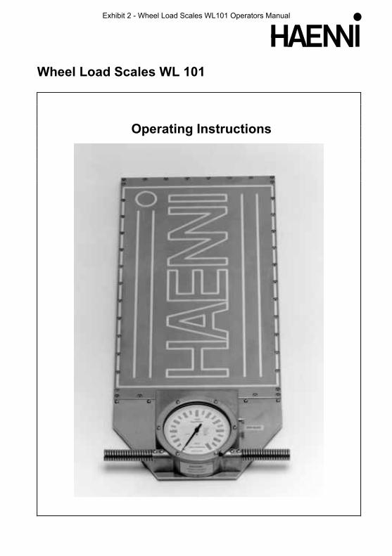
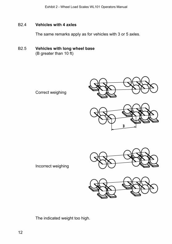
Appendix How to weigh correctly with the Wheel Load Scale Type WL 101 A Error sources at the weighing site A1 Weighing site gradient
Gradient Weighing Total weight Axle weight Wheel weight
unaffected unaffected unaffected
unaffected unaffected affected
unaffected affected affected
Total 5% unaffected affected affected
Total >5% affected affected affected
longitudinal 0% transversal 0%
longitudinal 0% transversal 5%
longitudinal 5% transversal 0%
8
A2 Uneven place of weighing Even place of weighing Correct weighing Crown Incorrect
weighing The indicated total weight is higher than on a flat surface. Hollow Incorrect
weighing The indicated total weight is lower than on a flat surface.
Exhibit 2 - Wheel Load Scales WL101 Operators Manual

7
Appendix How to weigh correctly with the Wheel Load Scale Type WL 101 A Error sources at the weighing site A1 Weighing site gradient
Gradient Weighing Total weight Axle weight Wheel weight
unaffected unaffected unaffected
unaffected unaffected affected
unaffected affected affected
Total 5% unaffected affected affected
Total >5% affected affected affected
longitudinal 0% transversal 0%
longitudinal 0% transversal 5%
longitudinal 5% transversal 0%
8
A2 Uneven place of weighing Even place of weighing Correct weighing Crown Incorrect
weighing The indicated total weight is higher than on a flat surface. Hollow Incorrect
weighing The indicated total weight is lower than on a flat surface.
Exhibit 2 - Wheel Load Scales WL101 Operators Manual

9
Even place of weighing Correct weighing The scale is correctly placed. The clearance between the scale
and the ground is not more than 10 mm. Uneven place of weighing Incorrect
weighing The clearance between the scale and the ground is more than
0.4 in. The scale is deformed too much
> 0.
4 in
>
0.4
in
10
B Sources of errors through the suspension of the
vehicles B1 Influence of the suspension on the weighing Front axle correctly weighed incorrect: the indication is too high incorrect: the indication is too high Result: total weight too high. The error can be avoided if both rear axles are weighed at the
same time with two additional scales or if the axle not being weighed, is supported with a dummy with the same thickness as the scale.
B2 Examples B2.1 General The rectangular plates under the wheels represent the wheel
load scale type WL 101 or levelers of similar thickness. Aside from exceptional cases always two or more scales should be used.
Exhibit 2 - Wheel Load Scales WL101 Operators Manual

11
B2.2 Vehicles with 2 axles Correct
weighing Incorrect
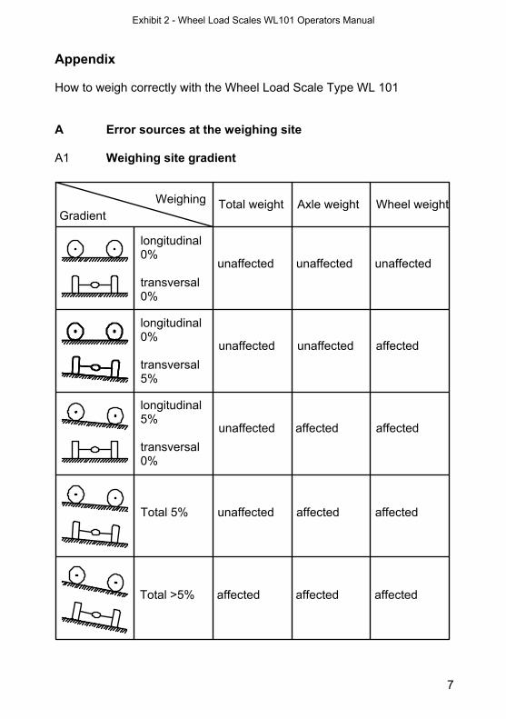
weighing B2.3. Vehicles with long wheel base (B greater than 10 ft)
Correct weighing
Incorrect weighing The indicated weight too high.
12
B2.4 Vehicles with 4 axles The same remarks apply as for vehicles with 3 or 5 axles. B2.5 Vehicles with long wheel base (B greater than 10 ft) Correct weighing Incorrect weighing The indicated weight too high.
Exhibit 2 - Wheel Load Scales WL101 Operators Manual
11
B2.2 Vehicles with 2 axles Correct
weighing Incorrect
weighing B2.3. Vehicles with long wheel base (B greater than 10 ft)
Correct weighing
Incorrect weighing The indicated weight too high.
12
B2.4 Vehicles with 4 axles The same remarks apply as for vehicles with 3 or 5 axles. B2.5 Vehicles with long wheel base (B greater than 10 ft) Correct weighing Incorrect weighing The indicated weight too high.
Exhibit 2 - Wheel Load Scales WL101 Operators Manual

13
C Errors because of „hard“ wheels Solid rubber and steel wheels need special precautions. For such
wheels the pad D 12590 must be used between the scale and the wheel to ensure that the load per area doesn’t exceed the value specified in chapter 1 „Technical Details“.
Correct weighing Pad D 12590 with deepening for proper centering of the load. Incorrect weighing The indicated weight may be far too low due to local overload.
the portable scale for all type of vehicles with rubber tires protects against overloading as well as insufficient loading assures the exact observance of the permissible total weights and axle loads can always and at any time be used without connections or ramps can easily be transported and put to use by one person alone is robust, does not require any maintenance, is practically unaffected by ambient temperature and is accurate Distributor:
Loadometer Corporation
Phone: 410-420-7535 or 800-753-6696 | Fax: 410-420 7537 [email protected]
A 8186.4
HAENNI 3303 Jegenstorf, Switzerland Phone +41 31 764 99 77 E-mail: [email protected] Fax +41 31 764 99 88 http://www.haenni-scales.com
111 Industry Lane Forest Hill, MD 21050-1621
03.10
Instruments Inc.
-
Exhibit 2 - Wheel Load Scales WL101 Operators Manual