Wheel Alignment For Trucks - enrdd.com · Wheel Alignment For Trucks ... with a 3 wire plug with...
48
Rev. 04 July 2006 ENG Wheel Alignment For Trucks Operating Manual
Transcript of Wheel Alignment For Trucks - enrdd.com · Wheel Alignment For Trucks ... with a 3 wire plug with...

Rev. 04 July 2006 ENG
Wheel Alignment
For Trucks
Operating Manual
2 of 48
(sw aligner_T 2.5.x )
Contents 1 – GENERAL INFORMATION.......................................................................................................................5
1.1 SUSPENSIONS ........................................................................................................................................5 1.2 GEOMETRICAL ATTITUDE OF THE MOTOR VEHICLE.................................................................5 1.3 TYPICAL ANGLES OF THE VEHICLE GEOMETRICAL ATTITUDE..............................................5
1.3.1 TOE-IN ..............................................................................................................................................6 1.3.2 WHEEL CAMBER............................................................................................................................7 1.3.3 Set-back..............................................................................................................................................7 1.3.4 Caster .................................................................................................................................................8 1.3.5 King Pin .............................................................................................................................................8 1.3.6 Included Angle...................................................................................................................................9 1.3.7 Toe – out on curve or steering symmetry ..........................................................................................9 1.3.8 Steering lock ....................................................................................................................................10 1.3.9 Thrust line ........................................................................................................................................10
2 – TARGET USE ............................................................................................................................................10 2.1 – FOREWORD .......................................................................................................................................10 2.2 - DEFINITIONS .....................................................................................................................................11
3 – TECHNICAL DATA..................................................................................................................................12 3.2 POWER SUPPLY AND CONSUMPTION ...........................................................................................12 3.3 MEASURING RANGES AND ACCURACY.......................................................................................13
4 – TRAINING OF THE APPOINTED PERSONNEL...................................................................................13 5 – EQUIPMENT MAKEUP............................................................................................................................13
5.1 MEASURING CABINET ......................................................................................................................13 5.2 HANDLING PC......................................................................................................................................14 5.3 PC KEYBOARD ....................................................................................................................................14 5.4 MONITOR..............................................................................................................................................14 5.5 PRINTER................................................................................................................................................15 5.6 DETECTORS .........................................................................................................................................15
5.6.1 Keyboards and detectors ..................................................................................................................17 5.7 WHEEL HOLDS ....................................................................................................................................17 5.7.1 ACCESSORY FOR WHEELS HOLDS - ADAPTOR –...................................................................18 5.8 ROTATING PLATES ............................................................................................................................21 5.9 PEDAL PUSHER ...................................................................................................................................21 5.10 STEERING LOCK ...............................................................................................................................22
6- ALIGNER SOFTWARE INSTALLATION ................................................................................................22 Only for BlueTooth Installation on Windows XP SP2:....................................................................................22 6.1 SWITCHING THE EQUIPMENT ON/OFF................................................................................................23 7 – Definitions of Function Keys......................................................................................................................23 8 – PROGRAM CONFIGURATION...............................................................................................................24
8.1 LANGUAGE SELECTION....................................................................................................................24 8.2 CALIBRATION ...............................................................................................................................25 8.3 User's calibration.....................................................................................................................................25 8.4 – CONFIGURATION OF THE SYSTEM PARAMETERS..................................................................25 8.5 CUSTOMER DATA BASE .............................................................................................................28

3 of 48
8.6 Repair Shop Name ............................................................................................................................28 9 – DIAGNOSIS AND VEHICLE REGISTRATION .....................................................................................28
9.1 WELCOME PAGE.................................................................................................................................28 9.2 Start, Customer details ......................................................................................................................29
9.2.1 Customer Archive file handling................................................................................................29 9.3 SELECTION OF THE VEHICLE MAKE AND MODEL ....................................................................29
9.3.1 Entering new motor vehicles or changing existing data in the Data base.................................30 9.4 DISPLAYING THE TECHNICAL DATA OF THE SELECTED VEHICLE ......................................31 9.5 PRELIMINARY OPERATIONS ...........................................................................................................32
9.5.1 Axle configuration ....................................................................................................................32 9.5.2 PRELIMINARY OPERATIONS FOR VEHICLE CHECK...........................................................33 9.5.3 “RUN-OUT” (or balance)................................................................................................................33
9.6 PREPARATION TO MEASUREMENTS .............................................................................................35 9.7 ALIGNING AND LEVELLING THE DETECTORS ...........................................................................35 9.8 STEERING PROCEDURE ....................................................................................................................38
9.8.1 STEERING ANGLE 20°, WITH THE ROTATING PLATES......................................................38 9.12 SUMMARY OF THE DIAGNOSIS AND REGISTRATION DATA.................................................42
10 FRONT AXIS SPOILER PROCEDURE ....................................................................................................43 11 DATA "FREEZING" PROCEDURE ..........................................................................................................44
11.1 JACK – UP PROCEDURE...................................................................................................................44 12 PRINTING THE MEASUREMENTS ........................................................................................................45

4 of 48
ATTENTION! This handbook is to be considered as an integral part of the product, and is aimed at providing the user with the instructions for use of the wheels attitude equipment. Read it carefully before starting to use the equipment; afterwards keep it, for the whole working life of the machine, in a known and easily accessible place and consult it should any doubt arise. Make sure that all the operators dealing with the equipment have accessibility to the handbook. Any damages resulting from failure in observing the indications given in this handbook and from improper uses of the machine releases the producer from any responsibility. The instructions concerning the detectors calibration (just for the specialized technical staff), are grouped in the specific handbook. IMPORTANT INSTRUCTIONS ABOUT SAFETY - The nameplate carrying the voltage and frequency data is located on the equipment rear side. Please take due note of what is shown on the plate. The plant must NEVER be connected to different voltage or frequency values than the ones shown. - This product is equipped with a 3 wire plug with incorporated earthing connection. The plug is to be connected only to a tap with earthing connection. If it is not possible to connect the plug to a tap of such type, please consult an electrician. DO NOT modify or make an improper use of the plug. - DO NOT switch off the PC located inside the equipment by disconnecting the plug, follow instead the procedure described in this handbook. Incorrect switching off of the PC may “corrupt” the files in the HARD-DISK. - The switch-off procedure described in this handbook does not cover the supports for detectors recharging, which are therefore continuously powered. - Maintenance operations must only and exclusively be carried out by authorized service personnel.

5 of 48
1 – GENERAL INFORMATION
1.1 SUSPENSIONS The suspensions consist of the elastic components, which join the wheels to the body or chassis of the vehicle; they take up the unevenness of the ground and guarantee a constant grip of the tyres. The suspension system is responsible for the comfort of the driving, for the maneuverability and for the roadholding.
1.2 GEOMETRICAL ATTITUDE OF THE MOTOR VEHICLE The term “GEOMETRICAL ATTITUDE OF THE MOTOR VEHICLE” refers to the geometrical state of all mechanical components which take part in determining the position of the wheels on the ground both in straightaway motion and on cornering. The equipment can control the motor vehicle attitude only when in static state, that is when the vehicle is stopped. When in a dynamical state (running vehicle) the attitude varies with regard to various factors, among which: the load conditions, the conditions of the suspensions, the structure of the mechanical components, the tyres pressure, etc. The data given by cars manufacturers refer to the static state of the vehicle, however they do also take into account the average dynamic variations. It is likewise to be considered that the vehicle can be used under various conditions: with the sole driver, with passengers, with a heavier or lighter luggage load, on straight roads or on roads with lots of curves, like mountain roads. These factors, added to the fact that the mechanical components have an “elastic” structure, do not allow a perfect adjustment of the attitude in every state; the user is therefore required to have a deep experience in order to be able to interpret the measures detected by the equipment, compared with the tolerances given by the car manufacturers.
1.3 TYPICAL ANGLES OF THE VEHICLE GEOMETRICAL ATTITUDE The angles concerning the vehicle front axle are: - Wheels toe-in - Wheel inclination or camber - Set-back - Caster - King pin - Included angle - Inner full steering lock - Outer full steering lock - Steering symmetry The angles concerning the vehicle rear axle are: - Wheels toe-in - Wheel inclination or camber - Set-back - Thrust line
6 of 48
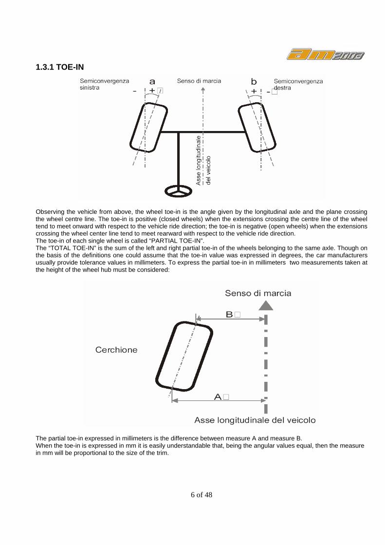
1.3.1 TOE-IN
Observing the vehicle from above, the wheel toe-in is the angle given by the longitudinal axle and the plane crossing the wheel centre line. The toe-in is positive (closed wheels) when the extensions crossing the centre line of the wheel tend to meet onward with respect to the vehicle ride direction; the toe-in is negative (open wheels) when the extensions crossing the wheel center line tend to meet rearward with respect to the vehicle ride direction. The toe-in of each single wheel is called “PARTIAL TOE-IN”. The “TOTAL TOE-IN” is the sum of the left and right partial toe-in of the wheels belonging to the same axle. Though on the basis of the definitions one could assume that the toe-in value was expressed in degrees, the car manufacturers usually provide tolerance values in millimeters. To express the partial toe-in in millimeters two measurements taken at the height of the wheel hub must be considered:
The partial toe-in expressed in millimeters is the difference between measure A and measure B. When the toe-in is expressed in mm it is easily understandable that, being the angular values equal, then the measure in mm will be proportional to the size of the trim.

7 of 48
1.3.2 WHEEL CAMBER
The wheel camber is the angle included between the wheel centre line and the ground vertical line when watching the vehicle front side. The camber is positive when the wheel upper side looks towards the outside of the vehicle. The camber is negative when the wheel upper side looks towards the inside of the vehicle.
1.3.3 Set-back
The set-back is the asymmetry value of a front or back wheel with respect to the opposite wheel on the same axle.
8 of 48
The set-back is positive when the right wheel is onward (according to the ride direction) with respect to the left wheel; it is negative when the right wheel is rearward (according to the ride direction) with respect to the left wheel. It may also be expressed in millimeters.
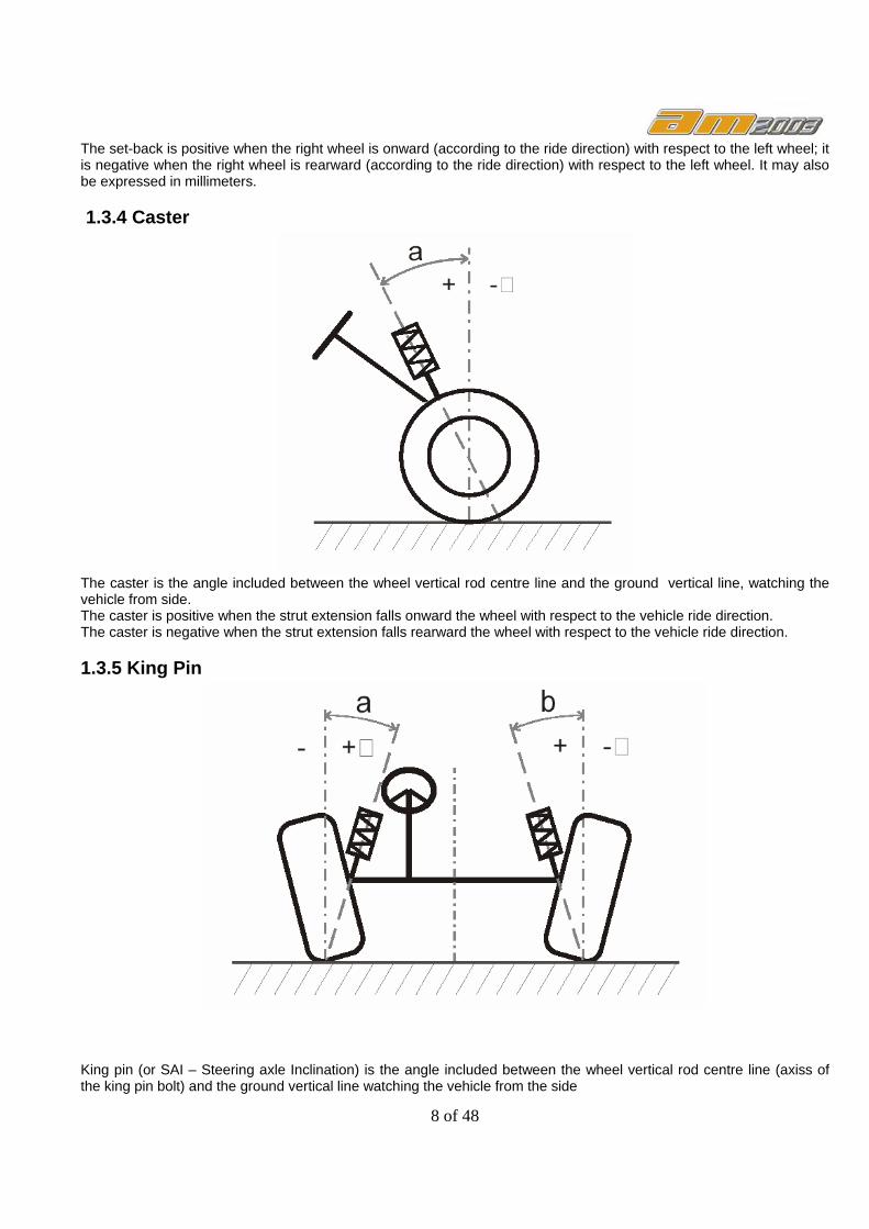
1.3.4 Caster
The caster is the angle included between the wheel vertical rod centre line and the ground vertical line, watching the vehicle from side. The caster is positive when the strut extension falls onward the wheel with respect to the vehicle ride direction. The caster is negative when the strut extension falls rearward the wheel with respect to the vehicle ride direction.
1.3.5 King Pin
King pin (or SAI – Steering axle Inclination) is the angle included between the wheel vertical rod centre line (axiss of the king pin bolt) and the ground vertical line watching the vehicle from the side

9 of 48
King pin is positive when the upper part of the strut is positioned towards the inside of the vehicle. King pin is negative when the upper part of the strut is positioned towards the outside of the vehicle.
1.3.6 Included Angle
the included angle is the angle included between the centre line of the wheel vertical rod (axis of the king pin bolt) and the centre line of the wheel. The included angle is simply the algebraic sum of the wheel inclination angles and the rod inclination.
1.3.7 Toe – out on curve or steering symmetry
When a vehicle turns, the wheels make different paths, therefore the inner wheel must steer more than the outer wheel; besides the value must be symmetrical when steering to the right or to the left. To measure the toe-out on turns proceed as follows: While steering to the left, measure the steering value of the inner wheel (the left one) while the outer wheel (the right one) steers at 20°. Steering to the right, measure the steering value of the inner wheel (the right one) while the outer wheel (the left one) steers at 20°.
10 of 48
Usually the steering boxes of the vehicles are designed in order to have the inner wheel steering of at least 1°÷1°30' more than the outer wheel when the latter steers at 20°. It is useful to evaluate the centering of the steering box.
1.3.8 Steering lock The steering lock is carried out the same way as the 20° steering: turn the steering wheel to the end of stroke and measure the steering value of the inner and outer wheels, steering both to the right and to the left.
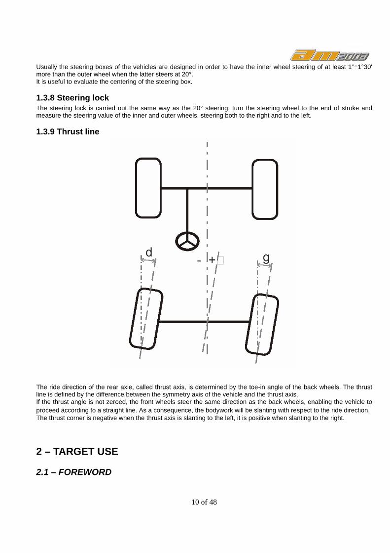
1.3.9 Thrust line
The ride direction of the rear axle, called thrust axis, is determined by the toe-in angle of the back wheels. The thrust line is defined by the difference between the symmetry axis of the vehicle and the thrust axis. If the thrust angle is not zeroed, the front wheels steer the same direction as the back wheels, enabling the vehicle to proceed according to a straight line. As a consequence, the bodywork will be slanting with respect to the ride direction. The thrust corner is negative when the thrust axis is slanting to the left, it is positive when slanting to the right.
2 – TARGET USE
2.1 – FOREWORD

11 of 48
No difference will be made in this handbook between the Am2003T_C and the Am2003T_BT models, as the sole difference is that version “C” is the “by cable” model, while version “BT” is the “by BlueTooth “model. In the “C” model the sensing arms are connected with the (RS232) serial port of the PC. In the “BT” model the sensing arms are NOT connected with one another and do not need a physical connection to the PC.
2.2 - DEFINITIONS The Am2003 system is an equipment designed for the total measurement of the vehicle typical angles. The measurement of the angles is carried out through four microprocessor technology detectors and a system for measuring and transmitting data by means of Bluetooth and infrared (with no cable connections between the detectors) To grant the transmission of the data and the measurement of the angles the max. length of the wheel base of a vehicle is 10 m. On the whole, the Am2003C system is similar to the Am2003BT model, but data communication between the single detectors and the Personal Computer is made by cable.

12 of 48
3 – TECHNICAL DATA 3.1 DIMENSIONS
Width (detectors included) = 1100mm Depth = 720mm Height (Monitor excluded) = 1250mm
3.2 POWER SUPPLY AND CONSUMPTION Control Unit (cabinet) Power supply: 230 Vac, single phase, 50/60 Hz Max absorbed power 300W Detectors Power supply: 7.2 V – 1.6 Ah lead battery Average working time with battery: 6 hours Charging time: 10 hours approx. LED TRACER: The battery loading operation for this tracer, is the same of the normal tracer. In case the battery of LED tracer are exhaust, is possible to use this with the cable mode. Power Supply / Battery Charger Important: The Radio detectors must be Switched OFF during battery charging. The BlueTooth detectors must be Switched ON during battery charging.

13 of 48
Feeder / Battery charger Power supply: 13,8V 5A (supplied) Max consumption during charging 2,5A Function temperature: +5°………….+40°C Relative humidity: 10%.............90% (40°C)
3.3 MEASURING RANGES AND ACCURACY
Measuring front and back axle
Measuring range Total measuring range
Toe-in ±2’ ±4° ±22° Set-back ±3’ ±4° ±22° Camber ±3’ ±6° ±22° Caster ±9’ ±18°
King Pin ±9’ ±18°
4 – TRAINING OF THE APPOINTED PERSONNEL The use of the equipment is only allowed to expressly trained and authorized personnel. The appointed personnel must be properly trained in order to learn the information required for a correct use of the machine, an efficient measurement, and to reach a working way in line with the manufacturer’s instructions. Should any doubt arise on the use and the maintenance of the machine, please refer to the instruction handbook. In case of doubt do not try to interpret the instructions, but promptly contact the authorized service centres or directly the technical service.
5 – EQUIPMENT MAKEUP
5.1 MEASURING CABINET The use of the cabinet is foreseen for all operations concerning the measuring; the cabinet is provided with electronical devices for the processing and management of the measures collected by the detectors.

14 of 48
Starting from the top: 1 - Monitor 17” SVGA. 2 – Keyboard, PC type, 105 keys 3 - Mouse 3 - Detectors 4 – Upper site (drawer) housing the colour printer 5 – Personal Computer casing (front door)
5.2 HANDLING PC Inside the cabinet, a handling PC is located, where the software is loaded. PC minimum requirements: Intel Pentium or AMD - 1300 Mhz Ram 256 Hard Disk 10GB CD-ROM Serial output RS232 Video card Svga 1024x768 Operating system WindowsXP SP2
5.3 PC KEYBOARD The equipment is provided with a PC type, 105 key, control keyboard, which acts as interface for the use of the program, for the setting during the first configuration, for the customizing of the vehicle data bank, for the client’s header and to enter the data related to the vehicle under diagnosis.
5.4 MONITOR The data are displayed by a colour 17” SVGA, high definition monitor. The optimum brightness and contrast is factory adjusted.

15 of 48
5.5 PRINTER The results are printed by ink jet printer, for A4 format paper. The instructions for printer use and maintenance are given in the handbook supplied with the printer itself. You are kindly invited to keep to the handbook contents.
5.6 DETECTORS The detectors of the equipment Am2003BT do not require any cable or cord connections for angle measurement. The detecting units consist of CCD type transducers, with infrared emission focus point.
1 – Control detector keyboard 2 – Kit of 3 signal LEDs for detector levelling 3 – Battery casing. Each detector is provided with a rechargeable battery, housed in the arm rear part: the battery is recharged when the detector is placed in its housing and connected to the cable provided. The detector is switched on by pressing any keys on the keyboard. To manually switch off the detector, move the arm to the vertical position (90°), and its inner sensor will switch off. The detector is switched off automatically when not used for more than 5 minutes approx.
2 1
3

16 of 48
The tracer above show, is that for Front wheels. The tracer for rear wheels is that show below (with only 2 sensors).
In the “level entry” configuration, we have the LED tracer, only for alignment of rear wheels.
In the picture above show is possible to view also the metal support, stretchable in the top section. N.B. the LED trace is very sensible to the infrared light. For this reason, when the LED tracer not running (are not in use), mustn’t be placed one in front of to the other, because is possible that LED tracer automatically starts the communication between them, with the consequent discharge of the battery . Therefore when not utilized the LED tracer must be put away NOT one in front of the other. The charge of battery is normal how for the Front tracer.
17 of 48
In case of the LED tracer are have the battery discharge, is possible to use them with the cable connection.
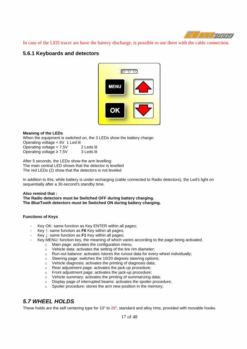
5.6.1 Keyboards and detectors
Meaning of the LEDs When the equipment is switched on, the 3 LEDs show the battery charge: Operating voltage < 6V 1 Led lit Operating voltage < 7,5V 2 Leds lit Operating voltage ≥ 7,5V 3 Leds lit After 5 seconds, the LEDs show the arm levelling: The main central LED shows that the detector is levelled The red LEDs (2) show that the detectors is not leveled In addition to this, while battery is under recharging (cable connected to Radio detectors), the Led's light on sequentially after a 30-second's standby time. Also remind that : The Radio detectors must be Switched OFF during battery charging. The BlueTooth detectors must be Switched ON during battery charging. Functions of Keys
- Key OK: same function as Key ENTER within all pages; - Key ↑: same function as F6 Key within all pages; - Key ↓: same function as F1 Key within all pages; - Key MENU: function key, the meaning of which varies according to the page being activated.
o Main page: activates the configuration menu; o Vehicle data: activates the setting of the tire rim diameter; o Run-out balance: activates /stores the runout data for every wheel individually; o Steering page: switches the 10/20 degrees steering options; o Vehicle diagnosis: activates the printing of diagnosis data; o Rear adjustment page: activates the jack-up procedure; o Front adjustment page: activates the jack-up procedure; o Vehicle summary: activates the printing of summarizing data; o Display page of interrupted beams: activates the spoiler procedure; o Spoiler procedure: stores the arm new position in the memory;
5.7 WHEEL HOLDS These holds are the self centering type for 10” to 26”, standard and alloy rims, provided with movable hooks.

18 of 48
With this equipment are always present the extension for hooks.
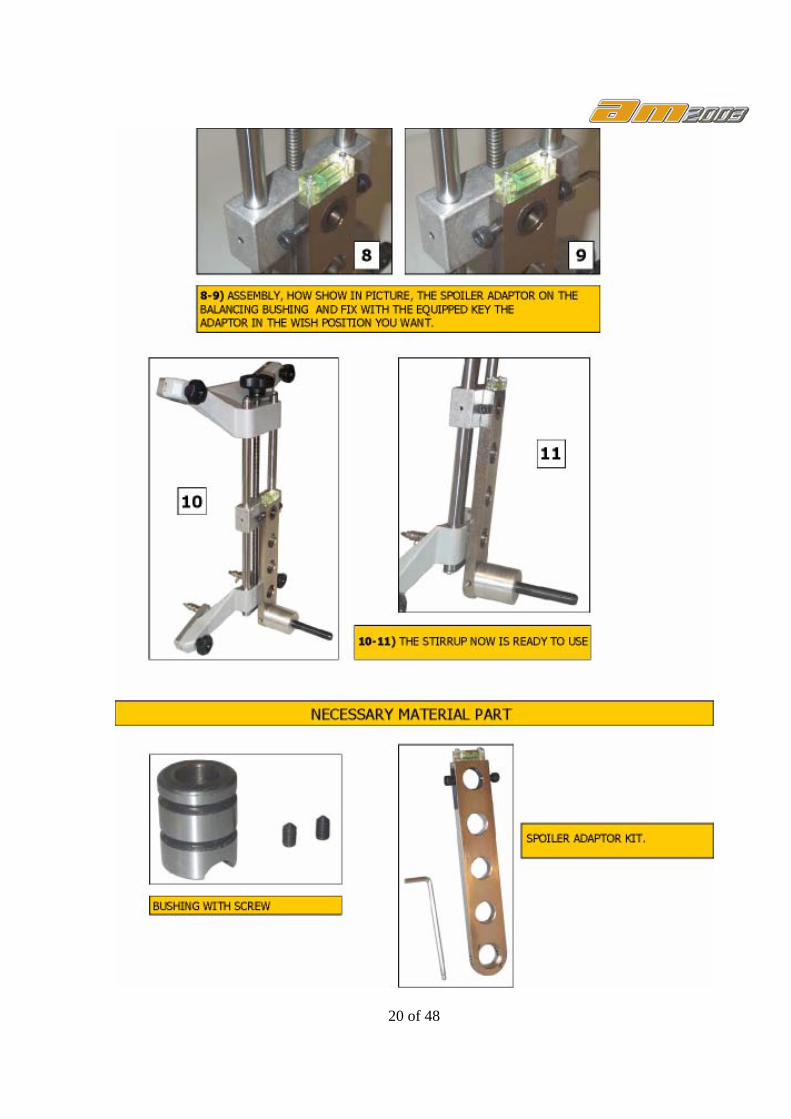
5.7.1 ACCESSORY FOR WHEELS HOLDS - ADAPTOR – If we must perform an alignment to the Truck but we have only the CAR tracer, is possible perform this action with the Adaptor accessory. Read the below explain and procedure for apply these adaptor:

19 of 48
20 of 48
21 of 48
5.8 ROTATING PLATES These rotating plates have a graduated scale for read the angle of steering procedure. This graduated scale is important when is used only two (Front) tracer, because when only the front tracer are used, the steering procedure by the Aligner software not is possible to perform.
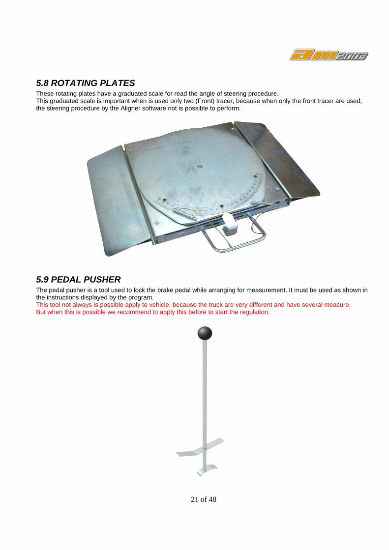
5.9 PEDAL PUSHER The pedal pusher is a tool used to lock the brake pedal while arranging for measurement. It must be used as shown in the instructions displayed by the program. This tool not always is possible apply to vehicle, because the truck are very different and have several measure. But when this is possible we recommend to apply this before to start the regulation.

22 of 48
5.10 STEERING LOCK This device is used to keep the steer in a locked position. It is used before starting the registration procedure, as specified in this handbook. This tool not always is possible apply to vehicle, because the truck are very different and have several measure. But when this is possible we recommend to apply this before to start the regulation.
6- ALIGNER SOFTWARE INSTALLATION Aligner software is delivered in form of a CDROM. Once the CDROM has been introduced in its PC unit, this software starts automatically and displays the first installation page which shows instructions regarding BlueTooth installation in Windows XP Service Pack2 and also other Windows versions. It is mandatory to follow exactly the instructions PRESCRIBED IN THE SERVICING MANUAL in order to prevent future problems. BlueTooth Installation
Only for BlueTooth Installation on Windows XP SP2: After Aligner install, is necessary to complete the installation for BlueTooth device. Place into a USB the Bluetooth device Turn-On all detector and run this file : ProjectInstall.exe and select Install placed in this directory: C:\WheelAligner\....... or C:\Program files\........\WheelAligner\..... Close this utility and Run Aligner icon on desktop.

23 of 48
If the installation BlueTooth not is run properly, Remove the installation by Run Project Install.exe and click on Remove, wait the end of procedure, and click on Install and try again.
NOTE: Not is recommend install this equipment on other operating system different of winXP SP2. The BlueTooth supplier not guarantee the complete compatibility, and not guarantee the simple
installation method.
6.1 SWITCHING THE EQUIPMENT ON/OFF To switch the equipment on and enter the program, open the door and switch on the PC located in the lower part. When the PC has been initialized by WindowsXP , click on the Aligner icon appearing on the desktop. The screen displayed is the program welcome page. Now, it is necessary to switch on the detectors too, by pressing the OK key on the keyboard. Upon operations completion, close Windows (it will switch off the PC, as well) and connect the detectors to the relevant cables for charge. The Radio detectors must be Switched OFF during battery charging. The BlueTooth detectors must be Switched ON during battery charging. The detectors can be switched off in two ways : by turning them by 90° or by pressing the OK key for over 5 seconds. ATTENTION! The switch off procedure does not affect the detectors recharging devices, that are still powered.
7 – Definitions of Function Keys It must be highlighted that the Software can be used by the keyboard; all functions are connected and can be activated by the function keys F1, F2, F3, F4, F5, F6 of the keyboard. But some function are possible also use the mouse. The lower part of the video pages show 4 boxes, that include the symbols identifying the function keys F1, F2, F3, F4 respectively. The following functions have been added and are operated by means of the following function keys : F9 if pressed while the first page is displayed, Aligner runs a demo F10 activates a History pdf document, containing the total list of changes and improvements (PDF Reader should
be available) F11 displays this Handbook (PDF Reader should be available) F12 shortcut to exit Aligner, from whichever location in the software.
24 of 48
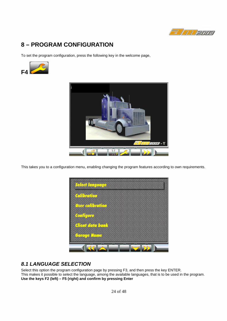
8 – PROGRAM CONFIGURATION To set the program configuration, press the following key in the welcome page,
F4
This takes you to a configuration menu, enabling changing the program features according to own requirements.
8.1 LANGUAGE SELECTION Select this option the program configuration page by pressing F3, and then press the key ENTER. This makes it possible to select the language, among the available languages, that is to be used in the program. Use the keys F2 (left) – F5 (right) and confirm by pressing Enter

25 of 48
8.2 CALIBRATION This page is used to check the detector correct operation as well as all data transmitted by the detectors to the Aligner software. For a detailed description of the "Calibration" page, refer to the “Servicing Manual” NOTICE THAT PRESSING THE F4 KEY WILL DISPLAY THE FOLLOWING MESSAGE: “Attention arm address change ”: this procedure allows to change the individual detector addresses. However this procedure may affect the detectors performance. For a correct use of this procedure refer to the “ Service Manual ”.
8.3 User's calibration This menu is used only to recalibrate the detectors; for AM2003 detectors, a calibration bar is imperatively required. As regards the procedure, please refer to the “Servicing Manual”
8.4 – CONFIGURATION OF THE SYSTEM PARAMETERS Select this option in the configuration page, as described above. The system parameters cannot be modified
26 of 48
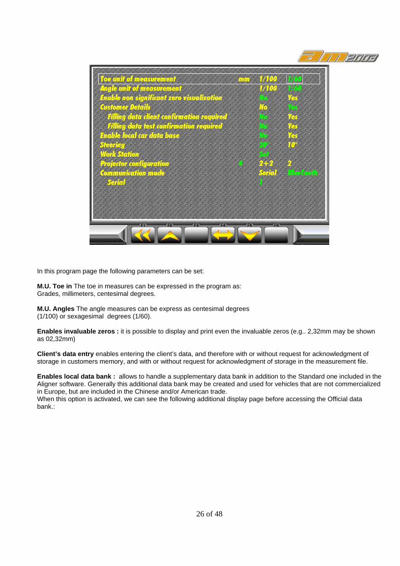
In this program page the following parameters can be set: M.U. Toe in The toe in measures can be expressed in the program as: Grades, millimeters, centesimal degrees. M.U. Angles The angle measures can be express as centesimal degrees (1/100) or sexagesimal degrees (1/60). Enables invaluable zeros : it is possible to display and print even the invaluable zeros (e.g.. 2,32mm may be shown as 02,32mm) Client’s data entry enables entering the client’s data, and therefore with or without request for acknowledgment of storage in customers memory, and with or without request for acknowledgment of storage in the measurement file. Enables local data bank : allows to handle a supplementary data bank in addition to the Standard one included in the Aligner software. Generally this additional data bank may be created and used for vehicles that are not commercialized in Europe, but are included in the Chinese and/or American trade. When this option is activated, we can see the following additional display page before accessing the Official data bank.:
27 of 48
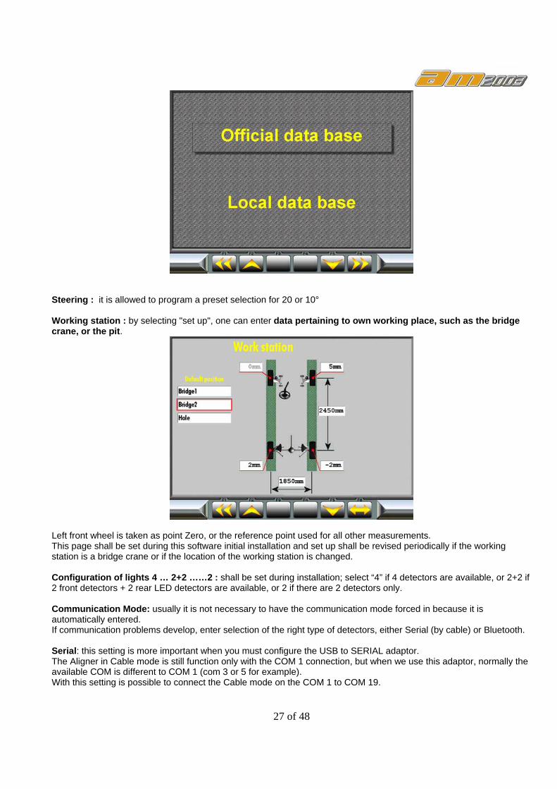
Steering : it is allowed to program a preset selection for 20 or 10° Working station : by selecting "set up", one can enter data pertaining to own working place, such as the bridge crane, or the pit.
Left front wheel is taken as point Zero, or the reference point used for all other measurements. This page shall be set during this software initial installation and set up shall be revised periodically if the working station is a bridge crane or if the location of the working station is changed. Configuration of lights 4 … 2+2 ……2 : shall be set during installation; select “4” if 4 detectors are available, or 2+2 if 2 front detectors + 2 rear LED detectors are available, or 2 if there are 2 detectors only. Communication Mode: usually it is not necessary to have the communication mode forced in because it is automatically entered. If communication problems develop, enter selection of the right type of detectors, either Serial (by cable) or Bluetooth. Serial: this setting is more important when you must configure the USB to SERIAL adaptor. The Aligner in Cable mode is still function only with the COM 1 connection, but when we use this adaptor, normally the available COM is different to COM 1 (com 3 or 5 for example). With this setting is possible to connect the Cable mode on the COM 1 to COM 19.
28 of 48
8.5 CUSTOMER DATA BASE (Customer Archives). In this page, it is possible to select a former customer whose data have been entered before and to check the previous test run and possibly print another hard copy of the results.
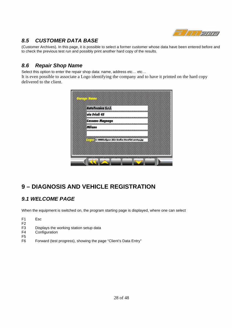
8.6 Repair Shop Name Select this option to enter the repair shop data: name, address etc… etc… It is even possible to associate a Logo identifying the company and to have it printed on the hard copy delivered to the client.
9 – DIAGNOSIS AND VEHICLE REGISTRATION
9.1 WELCOME PAGE When the equipment is switched on, the program starting page is displayed, where one can select F1 Esc F2 F3 Displays the working station setup data F4 Configuration F5 F6 Forward (test progress), showing the page “Client’s Data Entry”

29 of 48
9.2 Start, Customer details
Customer's and his motor vehicle data are entered in the "Customer data entry" page, but as regards the car Model and Manufacturer, these shall be obtained by pressing F6 and selecting these data directly in the motor vehicle database.
9.2.1 Customer Archive file handling By means of the F2 key, it is possible to remove definitely from the page shown above those customers who, for any reason, must be deleted from the archive file F3. Searching a motor vehicle (and its owner) can be made by entering the car license-plate number.
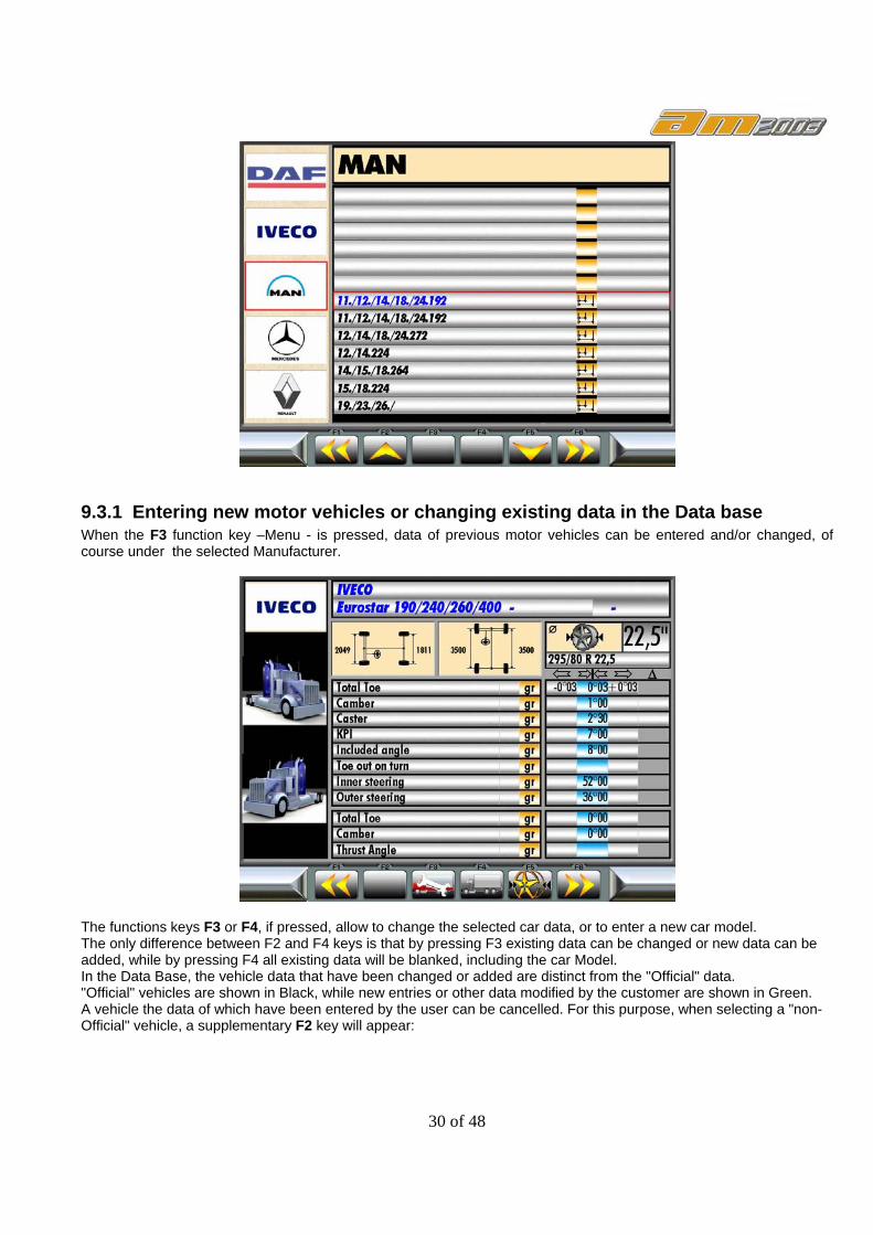
9.3 SELECTION OF THE VEHICLE MAKE AND MODEL To select the vehicle make, go to the page by pressing again the key F6; then press F2, F5 to select the Vehicle Make. Press the key F4 to select the Model section, then using the keys F2, F5 select the Vehicle Model. In the vehicle data bank, the technical data of over 700 industrial vehicles are available, but one can also enter customized vehicles.
30 of 48
9.3.1 Entering new motor vehicles or changing existing data in the Data base When the F3 function key –Menu - is pressed, data of previous motor vehicles can be entered and/or changed, of course under the selected Manufacturer.
The functions keys F3 or F4, if pressed, allow to change the selected car data, or to enter a new car model. The only difference between F2 and F4 keys is that by pressing F3 existing data can be changed or new data can be added, while by pressing F4 all existing data will be blanked, including the car Model. In the Data Base, the vehicle data that have been changed or added are distinct from the "Official" data. "Official" vehicles are shown in Black, while new entries or other data modified by the customer are shown in Green. A vehicle the data of which have been entered by the user can be cancelled. For this purpose, when selecting a "non-Official" vehicle, a supplementary F2 key will appear:
31 of 48
N.B. If reference values are lacking, the following values shall be considered : Zero shall be taken as half-the-sum of the initial values (left/right) and tolerances values shall be taken as : +/- 15’ for toe-in; +/-45’ for camber and +/- 1.5° for incidence/SAI.
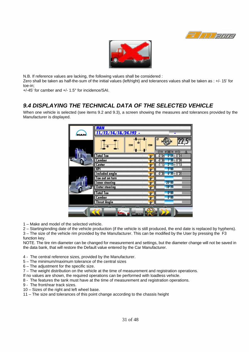
9.4 DISPLAYING THE TECHNICAL DATA OF THE SELECTED VEHICLE When one vehicle is selected (see items 9.2 and 9.3), a screen showing the measures and tolerances provided by the Manufacturer is displayed.
1 – Make and model of the selected vehicle. 2 – Starting/ending date of the vehicle production (if the vehicle is still produced, the end date is replaced by hyphens). 3 – The size of the vehicle rim provided by the Manufacturer. This can be modified by the User by pressing the F3 function key. NOTE. The tire rim diameter can be changed for measurement and settings, but the diameter change will not be saved in the data bank, that will restore the Default value entered by the Car Manufacturer. 4 - The central reference sizes, provided by the Manufacturer. 5 – The minimum/maximum tolerance of the central sizes 6 – The adjustment for the specific size. 7 – The weight distribution on the vehicle at the time of measurement and registration operations. If no values are shown, the required operations can be performed with loadless vehicle. 8 - The features the tank must have at the time of measurement and registration operations. 9 - The front/rear track sizes. 10 – Sizes of the right and left wheel base. 11 – The size and tolerances of this point change according to the chassis height

32 of 48
9.5 PRELIMINARY OPERATIONS
9.5.1 Axle configuration Select the correct configuration axle for the vehicle in test.
After have selected the correct axle configuration, is necessary confirm with F3 key. In case we have selected a not correct configuration axle, is possible change with F4 key and modify with F3 key. The page above show, allow the selection axle for plus common truck: One or two steering axle, with one or two motor axle, or one motor axle and one trolley (normally is autosteering). N.B. in case of steering Rear axle, the Aligner software not have procedure for check steering Rear axle. In that case this steering rear axle must be intend how normally axle motor or trolley. This axle normally is possible block manually with a mechanical activation, before test the alignment on thi axle, perform this Axle Block. During the front axle steering, the rear axle Must not steering. Push F6 to next page:

33 of 48
The RED Arrow show the axle in test. In this page is possible by press: - F2 key perform the Run-Out, - F4 key perform axle regulation - F5 key print out the data.
9.5.2 PRELIMINARY OPERATIONS FOR VEHICLE CHECK Prior to starting the check of the vehicle geometrical trim, it is required to: - Check and eliminate, if necessary, the plays on the suspensions and on the steer linkages. - Check and eliminate, if necessary, any hard spots or settling of the suspensions elastic components - Adjust the tyres pressure to the values specified by the Manufacturer. - Position and distribute the loads specified by the Manufacturer.
9.5.3 “RUN-OUT” (or balance) The “run-out” procedure is in a position to compensate any unbalance of the rims and clamps. This procedure can be skipped by pressing twice the key F4 , and preparation to measurement can be started immediately. This procedure can be activated also after vehicle registration. To perform the “run-out” procedure, press the key F2 in the vehicle data page; the following page is displayed:

34 of 48
The balance procedure can be run in 2 ways, the first mode, can be called by pressing the F4 key, is the following: - Bring the motor vehicle on the plates - Attach the detectors to the wheel rims - Raise the car - and, on every detector, adjust level, press the “Menu” key and turn by 180°, press the “Menu” key again - Lower the vehicle The second mode, called "Thrust" mode is not possible to perform on the higher vehicle but the procedure is the following:
- Bring the motor vehicle on the plates - Attach the detectors to the wheel rims - Push the car backwards until the detectors have turned by 180° (engage the hand brake) - Level all four detectors - press the F4 key on the PC keyboard - Bring the car on the plates again - Level the detectors again - Press the F4 key again
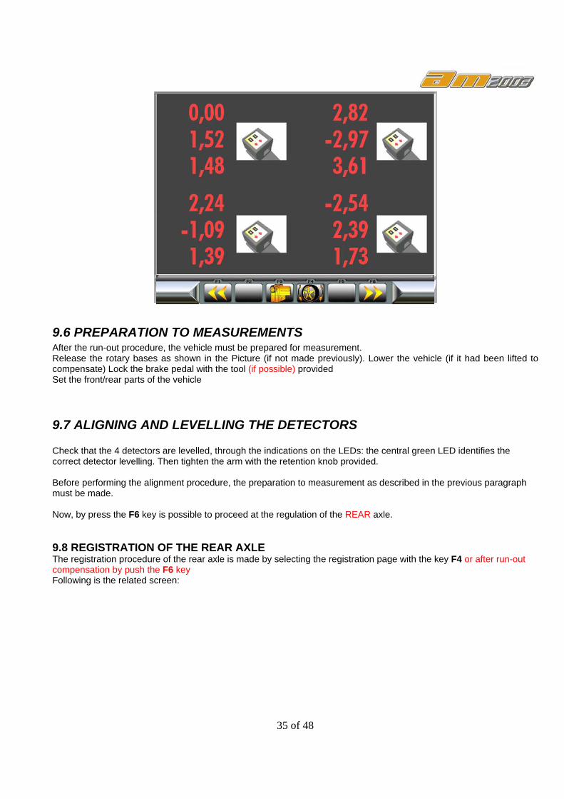
These operations shall complete the balance procedure and a page like that shown hereafter will be displayed, with all corrective data collected between point 1 (0°) and point 2 (180°)
35 of 48
9.6 PREPARATION TO MEASUREMENTS After the run-out procedure, the vehicle must be prepared for measurement. Release the rotary bases as shown in the Picture (if not made previously). Lower the vehicle (if it had been lifted to compensate) Lock the brake pedal with the tool (if possible) provided Set the front/rear parts of the vehicle
9.7 ALIGNING AND LEVELLING THE DETECTORS Check that the 4 detectors are levelled, through the indications on the LEDs: the central green LED identifies the correct detector levelling. Then tighten the arm with the retention knob provided. Before performing the alignment procedure, the preparation to measurement as described in the previous paragraph must be made. Now, by press the F6 key is possible to proceed at the regulation of the REAR axle. 9.8 REGISTRATION OF THE REAR AXLE The registration procedure of the rear axle is made by selecting the registration page with the key F4 or after run-out compensation by push the F6 key Following is the related screen:
36 of 48
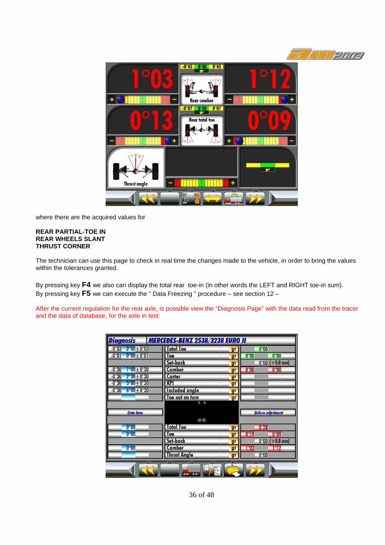
where there are the acquired values for REAR PARTIAL-TOE IN REAR WHEELS SLANT THRUST CORNER The technician can use this page to check in real time the changes made to the vehicle, in order to bring the values within the tolerances granted. By pressing key F4 we also can display the total rear toe-in (in other words the LEFT and RIGHT toe-in sum). By pressing key F5 we can execute the “ Data Freezing ” procedure – see section 12 – After the current regulation for the rear axle, is possible view the “Diagnosis Page” with the data read from the tracer and the data of database, for the axle in test:

37 of 48
In this page are present the F2 key for scroll the axle and the related diagnosis. The F3 key is for select an other vehicle. The F4 key is for enable /disable the color for data show in “measured parameters” The F5 key is for print the “Diagnosis page” (with the color or not, in accord to the previous selection) The F6 key for proceed to the test for next axle:
Also for this axle is possible perform the test and the regulation how the previous axle and Diagnostic Screen:
When perform the diagnosis for the rear axle, is possible go to the Front axle, by push the F6 key:

38 of 48
9.8 STEERING PROCEDURE When the detectors are aligned and leveled, the steering procedure can start, in order to determine the following measurements: - Incidence - Strut slant - Included angle N.B. By pressing the F2 key, the steering procedure can be stepped over and the "Detected Parameters" page displayed directly. Obviously, we shall not be able to get complete parameter readings. This procedure not is possible to perform if Only 2 tracer are used. In this case only with the graduated plate is possible to measure the internal steering and external steering, in manual mode.
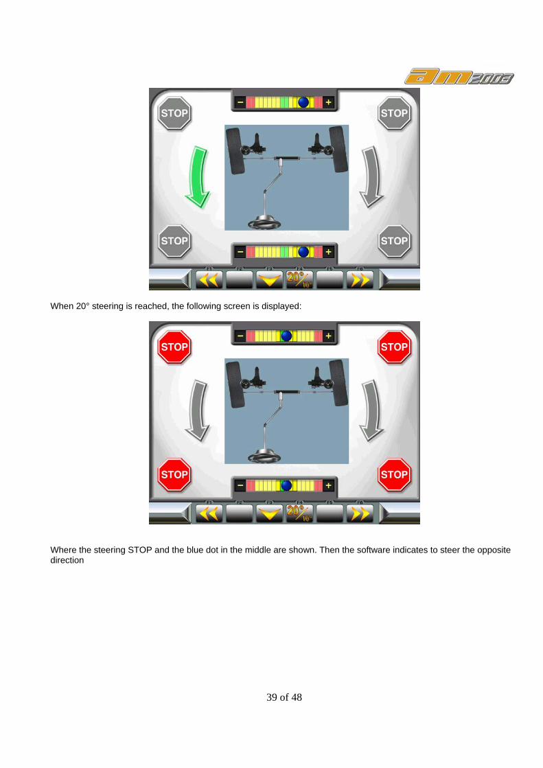
9.8.1 STEERING ANGLE 20°, WITH THE ROTATING PLATES Rotate the steer to the left: the steering level indicator (referring to the left wheel) moves to the left according to the steering. It must be moved until it matches the steering final point (shown by the arrows, and corresponding to a value of -20° ± 1'). Following is the screen displayed:
39 of 48
When 20° steering is reached, the following screen is displayed:
Where the steering STOP and the blue dot in the middle are shown. Then the software indicates to steer the opposite direction
40 of 48
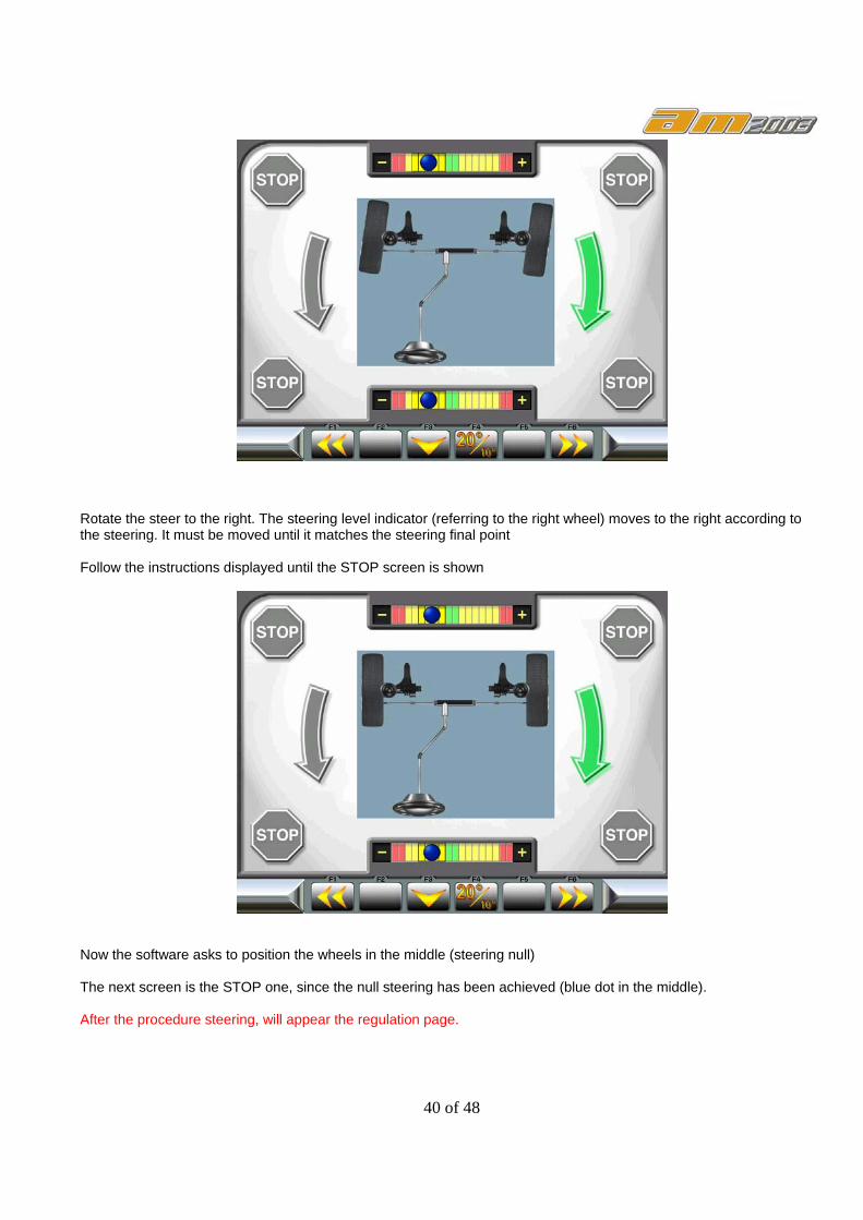
Rotate the steer to the right. The steering level indicator (referring to the right wheel) moves to the right according to the steering. It must be moved until it matches the steering final point Follow the instructions displayed until the STOP screen is shown
Now the software asks to position the wheels in the middle (steering null) The next screen is the STOP one, since the null steering has been achieved (blue dot in the middle). After the procedure steering, will appear the regulation page.

41 of 48
9.11 FRONT AXLE REGISTRATION The registration procedure of the front axle is made simply wait the next page appear. Is the steering procedure not is request, push F3 key for skip the steering procedure.
this page shows the acquired values for: FRONT PARTIAL-TOE IN CASTER FRONT WHEEL SLANT By pressing key F4 we can display the toe-in (total) value as the sum of LEFT and RIGHT toe-in By push the F2 key is possible perform the regulation of caster with freeze the toe data. The grey value mean that the value is Freeze, blocked, in this manner this data not change during the toe regulation or other. By pressing key F3 we will display the Axle Toe-in page:
AXLE TOE-IN: meaning:

42 of 48
Axle Toe-in: the value shown in the upper part of the display is the measured value with respect to the reference point which is the Front LEFT wheel.
Tread Delta… the value overmarked in green is the difference in mm between the width of the front and of the rear axles as indicated by the Car Manufacturer. The values overmarked in white are measured values in mm and degrees.
Pitch Delta………. the value overmarked in green is the max tolerance indicated by the Car Manufacturer regarding the LEFT side and the RIGHT side pitch. The measured values in mm and degrees are overmarked in white.
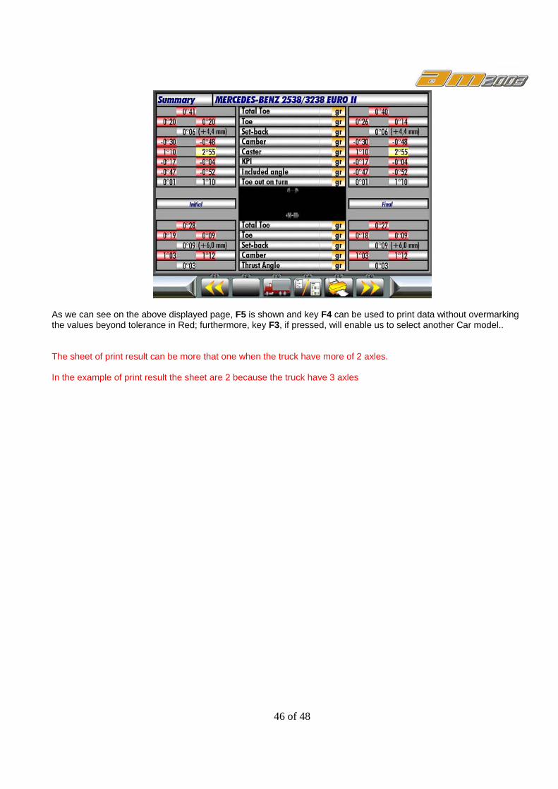
9.12 SUMMARY OF THE DIAGNOSIS AND REGISTRATION DATA Upon completion of adjustments, the page carrying the overall results can be displayed, with all measurements taken on the vehicle.
By pressing key F4 we will be able to display/cancel the Green, Yellow, Red over markings and with key F5 is possible to print the result in b/n or color mode.
From this page, key F3 allows to select another motor car in the data bank, or with F1 key repeat the regulation for improve the results.
Conversely, if we go back to the Summary page, we can press keys F2 and F3 to repeat or improve the settings of the rear and/or the front axle.

43 of 48
10 FRONT AXIS SPOILER PROCEDURE During the detector aligning and levelling operations, beware that the vehicle under test might be equipped with a front spoiler preventing the front detectors from communicating between each other. If communication between the detectors is inhibited, this problem is automatically detected and managed by the program, which will display a page like the following :
press the F3 key. Once the execution of the front axis procedure has been acknowledged, the following display will be shown:
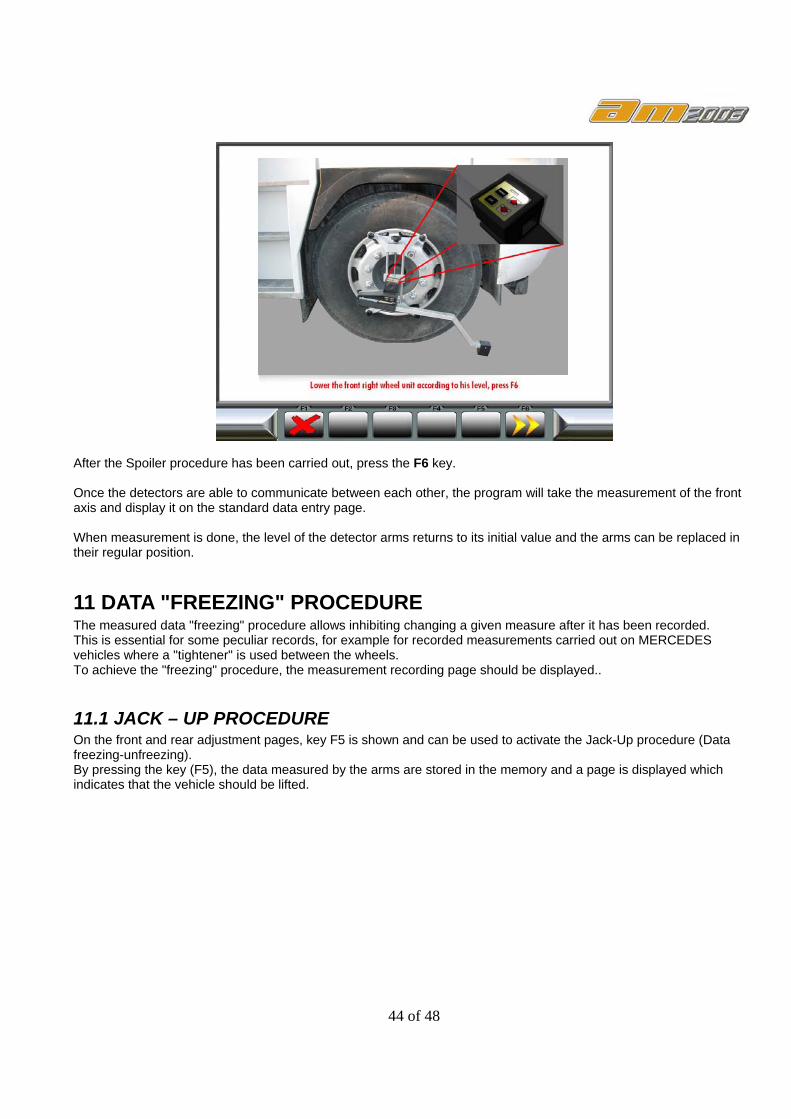
After pressing the F3 key, the front left detector must be inclined until the CCD sensor is seen under the spoiler. By pressing OK on the detector, the arm gets levelled and the position whereon the right arm should be placed is calculated. The right arm should be inclined manually until it reaches its new level position (which matches the left detector positioning).
44 of 48
After the Spoiler procedure has been carried out, press the F6 key. Once the detectors are able to communicate between each other, the program will take the measurement of the front axis and display it on the standard data entry page. When measurement is done, the level of the detector arms returns to its initial value and the arms can be replaced in their regular position.
11 DATA "FREEZING" PROCEDURE The measured data "freezing" procedure allows inhibiting changing a given measure after it has been recorded. This is essential for some peculiar records, for example for recorded measurements carried out on MERCEDES vehicles where a "tightener" is used between the wheels. To achieve the "freezing" procedure, the measurement recording page should be displayed..
11.1 JACK – UP PROCEDURE On the front and rear adjustment pages, key F5 is shown and can be used to activate the Jack-Up procedure (Data freezing-unfreezing). By pressing the key (F5), the data measured by the arms are stored in the memory and a page is displayed which indicates that the vehicle should be lifted.

45 of 48
After lifting the vehicle (that should be at stop), press key F6 (YES) again; this will display once more the data on the adjustment pages, showing the same (frozen) data values as originally. Once adjustments have been done, press key F5 to activate the car lowering procedure and to display again the real-time measurements.
12 PRINTING THE MEASUREMENTS On pages where printing facility is available, an icon appears in the lower portion of the page, featuring a printer; this is associated to key F5 which, if pressed, will allow to print the following data: 1 - Car Manufacturer's Logo. 2 - Space available to enter the workshop personalized data. 3 - Date and time of the end of test, automatically processed. 4 - Identifying data of the vehicle being tested and of its owner (refer to paragraph.9.20). 5 - Manufacturing data of the vehicle under test 6 - Diagnosis data of the vehicle under test. 7 - Data of the vehicle, recorded after the test. 8 - Front axis data Chart 9 - Rear axis data Chart WHEN PRINTED, REFERENCE VALUES THAT ARE DIFFERENT FROM THE ORIGINAL ONES ARE MARKED WITH AN ASTERISK (*)
46 of 48
As we can see on the above displayed page, F5 is shown and key F4 can be used to print data without overmarking the values beyond tolerance in Red; furthermore, key F3, if pressed, will enable us to select another Car model..
The sheet of print result can be more that one when the truck have more of 2 axles. In the example of print result the sheet are 2 because the truck have 3 axles

47 of 48

48 of 48