
What's New in SolidWorks 2009 › sw › docs › WhatsNew2009(1).pdf · PhotoView360.....136
173
What's New in SolidWorks 2009
Transcript of What's New in SolidWorks 2009 › sw › docs › WhatsNew2009(1).pdf · PhotoView360.....136

What's New in SolidWorks 2009

Contents
Notices..............................................................................................................................ix
Introduction.......................................................................................................................xiAbout This Book......................................................................................................................................xiUsing This Book......................................................................................................................................xiConverting Files to SolidWorks 2009.....................................................................................................xiiProduct Name Changes.........................................................................................................................xii
1 Fundamentals..............................................................................................................14Callout Improvements............................................................................................................................14Converting Files to the Current Version of SolidWorks.........................................................................14Custom Properties.................................................................................................................................15
Customizing the Custom Properties Tab..........................................................................................15Entering Properties...........................................................................................................................16
View Orientation Enhancements...........................................................................................................16Zoom Enhancements.............................................................................................................................17Using the Magnifying Glass...................................................................................................................17Moving the CommandManager and PropertyManager .........................................................................19Improving User Interface Consistency...................................................................................................19
2 Materials and Appearances.........................................................................................21Materials................................................................................................................................................21
Unified Materials Database and User Interface................................................................................21Displaying the Material Dialog Box...................................................................................................21Working With Materials.....................................................................................................................21
Appearances..........................................................................................................................................23Appearances Include Colors and Textures......................................................................................23Pop-up Toolbar.................................................................................................................................23Rough Draft Appearance..................................................................................................................23
3 Sketching.....................................................................................................................26Move, Copy, and Rotate in 3D Sketches...............................................................................................26
Moving 3D Sketch Entities................................................................................................................26Improved Functionality for Splines.........................................................................................................27Creating Equation Driven Curves..........................................................................................................27Ghost Images of Missing Sketch Entities..............................................................................................28
Displaying a Ghost Image of a Missing Sketch Entity......................................................................28Numeric Sketch Input.............................................................................................................................29
Enabling Numeric Input....................................................................................................................29
ii

Specifying Numeric Input..................................................................................................................29Offsetting Infinite Lines..........................................................................................................................30Repair Sketch Enhancements...............................................................................................................30Resizing Sketches in Instant3D.............................................................................................................30Slot Sketch Entity...................................................................................................................................31
Creating a Straight Slot....................................................................................................................31Stretching Sketch Geometry..................................................................................................................32Using Blocks in Sketches.......................................................................................................................33
Saving a Sketch to a Block File........................................................................................................33Saving Sketches in the Design Library.............................................................................................33
Sketch Dimensions of Zero and Negative Values.................................................................................33Reversing a Position Dimension......................................................................................................34
4 Features.......................................................................................................................35General..................................................................................................................................................35
Missing Reference Ghosting............................................................................................................35Boundary Features................................................................................................................................37Extrudes and Slots.................................................................................................................................38Fastening Features................................................................................................................................38Freeform Features.................................................................................................................................38Instant3D................................................................................................................................................39
Instant3D in Assemblies...................................................................................................................39Editing Sketches in Instant3D..........................................................................................................41Instant3D Live Section Planes.........................................................................................................42Instant3D and Mirrors or Patterns....................................................................................................44Instant3D and Move Face Features.................................................................................................44Instant3D Weldments.......................................................................................................................45
Lip and Groove Fastening Features......................................................................................................47Ribs........................................................................................................................................................48Solid Sweep Cuts...................................................................................................................................48
5 Parts.............................................................................................................................51Dual Dimensions for Measurement Results..........................................................................................51Dimensions in Mirrored and Derived Parts............................................................................................52Custom and Default File Properties in Equations..................................................................................53Changing Parts Display Characteristics................................................................................................53Reattach Derived Parts..........................................................................................................................54
Reattaching Existing Derived Parts..................................................................................................55Reattaching Parts When You Change Trim Tools...........................................................................55
Custom Properties Assigned to Parts....................................................................................................56Sensors..................................................................................................................................................56Mold Design...........................................................................................................................................56
Analysis Tools..................................................................................................................................56Sheet Metal............................................................................................................................................57
Convert to Sheet Metal.....................................................................................................................57
iii
Contents

Expanded Sheet Metal Gauge/Bend Table......................................................................................60Beveled/Chamfered Edges with Sheet Metal...................................................................................61Cross Breaks....................................................................................................................................62
Weldments.............................................................................................................................................63Groups..............................................................................................................................................63Working With Groups.......................................................................................................................63Working with Enhanced Trim and Extend Tool................................................................................65Creating Gussets with Chamfers......................................................................................................66End Caps..........................................................................................................................................67BOMs and Weldments......................................................................................................................68
6 Assemblies...................................................................................................................69General..................................................................................................................................................69
Custom Properties............................................................................................................................69Design Clipart...................................................................................................................................69Equations..........................................................................................................................................69Instant3D in Assemblies...................................................................................................................69Measurements..................................................................................................................................70Missing Reference Ghosting for Mates............................................................................................70Selection Tools.................................................................................................................................70
Large Assemblies..................................................................................................................................70Performance.....................................................................................................................................70Assemblies Larger than One Kilometer............................................................................................70Mate References in Lightweight Assemblies....................................................................................71Motion Studies in Lightweight Assemblies.......................................................................................71SpeedPak.........................................................................................................................................71Unloading Hidden Components.......................................................................................................71
Assembly Features in Parts...................................................................................................................71Bills of Materials in Assembly Documents.............................................................................................72Clearance Verification............................................................................................................................73Hinge Mates...........................................................................................................................................73Sensors..................................................................................................................................................74SpeedPak..............................................................................................................................................75
Creating a SpeedPak.......................................................................................................................75Inserting a SpeedPak.......................................................................................................................77
7 Motion Studies.............................................................................................................78General..................................................................................................................................................78
Name Changes.................................................................................................................................78Lightweight Assembly Support.........................................................................................................78Configuration-specific Motion Studies..............................................................................................78
Design Library for Motion Elements.......................................................................................................78Redundant Constraint Force Results.....................................................................................................79Motion for Layout Sketches ..................................................................................................................79Mates.....................................................................................................................................................80
iv
Contents

Path Mates.......................................................................................................................................80Mate Location Points........................................................................................................................81Motion Study-specific Mates............................................................................................................82
8 Drawings and Detailing................................................................................................85Customized Drafting Standards.............................................................................................................85
Overall Drafting Standards and Base Detail Standards...................................................................86Document Layer Defaults.................................................................................................................87Custom Line Thickness and Style....................................................................................................87Detailing Previews for Document Properties....................................................................................88
Bills of Materials (BOMs).......................................................................................................................88Copying Assembly BOMs into Referenced Drawings......................................................................88Restructuring BOMs.........................................................................................................................89Detailed Weldment Cut Lists in BOMs.............................................................................................90Item Numbering................................................................................................................................90
Detail Positioning...................................................................................................................................91Positioning Notes..............................................................................................................................91Attaching Dimension Extension Lines..............................................................................................92Jogging Extension Lines..................................................................................................................92Dimension Leader Control for Same-sized Features ......................................................................92Multiple Jogs for Dimensions and Callouts......................................................................................94
Print Options for Drawings.....................................................................................................................94Printing Drawings from Zoomed Selections.....................................................................................94Custom Line Thickness for Print Settings........................................................................................94
Title Blocks in Drawing Sheets..............................................................................................................95Title Block Management...................................................................................................................95
Favorites are Renamed to Style............................................................................................................97Format Painter.......................................................................................................................................97
Using Format Painter........................................................................................................................97Detailing for Sketch Slots ......................................................................................................................98General..................................................................................................................................................99
Cancelling Long Operations for Drawings........................................................................................99Exporting Tables to Excel.................................................................................................................99Opening Multi-sheet Drawings in Quick View................................................................................100Document Properties Options Reorganization...............................................................................100Lightweight Assembly Drawings.....................................................................................................100
9 Tolerancing................................................................................................................101Intersect Line Features........................................................................................................................101ISO Standards Support........................................................................................................................102Orientation Constraints........................................................................................................................105Redundant Dimensions........................................................................................................................106Tangency Constraints..........................................................................................................................107
10 SolidWorks Simulation.............................................................................................108
v
Contents

Product Name Changes.......................................................................................................................108Simulation Workflow............................................................................................................................109
User Interface.................................................................................................................................109Managing Simulation Studies.........................................................................................................111General...........................................................................................................................................112
Simulation Studies...............................................................................................................................112Simulation Advisor..........................................................................................................................112Sensors..........................................................................................................................................112Material...........................................................................................................................................113(Premium) Composite Shells..........................................................................................................114Beams............................................................................................................................................118(Professional) Thermal Studies......................................................................................................119(Professional) Geometry from Deformed Shape............................................................................119Stress/Deformation.........................................................................................................................120(Premium) Remote Load/Mass for Linear Dynamic Studies..........................................................120
Assemblies...........................................................................................................................................121Enhancements to Assembly Modeling...........................................................................................121Sheet Metal Parts...........................................................................................................................122Study Tree Enhancements ............................................................................................................122
Connectors...........................................................................................................................................122Factor of Safety for Connectors.....................................................................................................122Bolt Connectors..............................................................................................................................124Pin Connectors...............................................................................................................................125Bearing Connectors........................................................................................................................125
Mesh....................................................................................................................................................126Mesh Selection ..............................................................................................................................126Curvature-based Mesher................................................................................................................127Mesh Control..................................................................................................................................128Simplify Model for Meshing............................................................................................................128
Contact and Bonding...........................................................................................................................128Contact for Nonlinear Studies........................................................................................................128No Penetration and Shrink Fit Contact...........................................................................................128Bonding..........................................................................................................................................129
Result Viewing.....................................................................................................................................130Factor of Safety Check...................................................................................................................130Results............................................................................................................................................131Compare Results............................................................................................................................132
11 Other Functionality...................................................................................................133Installation............................................................................................................................................133
Administrative Image Configuration and Deployment....................................................................133Installation Manager Support for Manually Downloading Files......................................................134Installation Error Message Links....................................................................................................134
Application Programming Interface......................................................................................................134DWGeditor ..........................................................................................................................................135
vi
Contents

PhotoView 360.....................................................................................................................................136SolidWorks eDrawings.........................................................................................................................137
Graphics Hardware Acceleration Options......................................................................................137Appearances and Scenes..............................................................................................................137Assembly Bills of Materials in eDrawings.......................................................................................137
SolidWorks Rx.....................................................................................................................................137Problem Capture............................................................................................................................137
12 SolidWorks Professional..........................................................................................139FeatureWorks......................................................................................................................................139
General ..........................................................................................................................................139Automatic Dimensions and Relations.............................................................................................140Base Loft Recognition....................................................................................................................141End Conditions for Holes and Cut Extrudes...................................................................................142Mirror Patterns................................................................................................................................142Resize Tool.....................................................................................................................................143
PhotoWorks.........................................................................................................................................144Preview Window.............................................................................................................................144Abstract Scenes.............................................................................................................................144Aspect Ratio...................................................................................................................................147
Design Checker...................................................................................................................................149User Interface.................................................................................................................................149New Validation Checks...................................................................................................................149Custom Checks..............................................................................................................................150Specifying a File Location .............................................................................................................150Validating Documents Sequentially................................................................................................150New Result Category: Not Applicable Checks...............................................................................151
SolidWorks Tools.................................................................................................................................151Task Scheduler...............................................................................................................................151Property Tab Builder.......................................................................................................................151
SolidWorks Utilities..............................................................................................................................151General...........................................................................................................................................151Coordinate Systems Alignment......................................................................................................152Symmetry Check............................................................................................................................153
Toolbox................................................................................................................................................154Enabling SolidWorks Toolbox........................................................................................................154SolidWorks Toolbox Configuration.................................................................................................155Unloading Toolbox Components....................................................................................................156Graphical Sizing Tools....................................................................................................................156
13 SolidWorks Premium................................................................................................157CircuitWorks.........................................................................................................................................157
CircuitWorks Models ......................................................................................................................157User Interface.................................................................................................................................157Filtering...........................................................................................................................................158
vii
Contents

Generating a Model........................................................................................................................158ScanTo3D............................................................................................................................................160
Curve Wizard..................................................................................................................................160Routing.................................................................................................................................................160
General...........................................................................................................................................160Error Messages..............................................................................................................................161Point-to-Point Routes.....................................................................................................................161Toolbars..........................................................................................................................................161Electrical Routes.............................................................................................................................162
TolAnalyst............................................................................................................................................165Constructed Features.....................................................................................................................165Fixed and Floating Fastener Assemblies.......................................................................................167
viii
Contents

Notices© 1995-2008, Dassault SystèmesDassault Systèmes SolidWorks Corporation, a Dassault Systèmes S.A. company.300 Baker Avenue, Concord, Mass. 01742 USA. All Rights Reserved.
PatentsU.S. Patents 5,815,154; 6,219,049; 6,219,055; 6,603,486; 6,611,725; 6,844,877; 6,898,560;6,906,712; 7,079,990; 7,184,044; and foreign patents, (e.g., EP 1,116,190 and JP 3,517,643).U.S. and foreign patents pending.
The information and the software discussed in this document are subject to change withoutnotice and are not commitments by Dassault Systèmes SolidWorks Corporation (DS SolidWorks).
No material may be reproduced or transmitted in any form or by any means, electronic ormechanical, for any purpose without the express written permission of DS SolidWorks.
The software discussed in this document is furnished under a license and may be used orcopied only in accordance with the terms of this license. All warranties given by DS SolidWorksas to the software and documentation are set forth in the SolidWorks Corporation License andSubscription Service Agreement, and nothing stated in, or implied by, this document or itscontents shall be considered or deemed a modification or amendment of such warranties.
Trademarks and CopyrightsSolidWorks, 3D PartStream.NET, 3D ContentCentral, DWGeditor, PDMWorks, eDrawings, andthe eDrawings logo are registered trademarks and FeatureManager is a jointly owned registeredtrademark of DS SolidWorks.
Enterprise PDM and SolidWorks 2009 are product names of DS SolidWorks.
FloXpress, DWGseries, DWGgateway, Feature Palette, PhotoWorks, TolAnalyst, andXchangeWorks are trademarks of DS SolidWorks.
FeatureWorks is a registered trademark of Geometric Software Solutions Co. Ltd.
Other brand or product names are trademarks or registered trademarks of their respectiveholders.
COMMERCIAL COMPUTER SOFTWARE - PROPRIETARY
U.S. Government Restricted Rights. Use, duplication, or disclosure by the government is subjectto restrictions as set forth in FAR 52.227-19 (Commercial Computer Software - RestrictedRights), DFARS 227.7202 (Commercial Computer Software and Commercial Computer SoftwareDocumentation), and in the license agreement, as applicable.
Contractor/Manufacturer:
Dassault Systèmes SolidWorks Corporation, 300 Baker Avenue, Concord, Massachusetts 01742USA
Portions of this software © 1990-2008 Siemens Product Lifecycle Management Software III(GB) Ltd.
© 1998-2008 Geometric Software Solutions Co. Ltd.,
© 1986-2008 mental images GmbH & Co. KG,
ix

© 1996-2008 Microsoft Corporation
Outside In® Viewer Technology, © 1992-2008 Stellent Chicago Sales, Inc.
© 2000-2008 Tech Soft 3D
© 1998-2008 3Dconnexion, IntelliCAD Technology Consortium, Independent JPEG Group. AllRights Reserved.
Portions of this software incorporate PhysX™ by NVIDIA 2006 - 2008.
Portions of this software are copyrighted by and are the property of UGS Corp. © 2008.
Portions of this software © 2001 - 2008 Luxology, Inc. All Rights Reserved, Patents Pending.
Copyright 1984-2008 Adobe Systems Inc. and its licensors. All rights reserved.
Protected by U.S. Patents 5,929,866; 5,943,063; 6,289,364; 6,563,502; 6,639,593; 6,754,382;Patents Pending.
Adobe, the Adobe logo, Acrobat, the Adobe PDF logo, Distiller and Reader are registeredtrademarks or trademarks of Adobe Systems Inc. in the U.S. and other countries. For morecopyright information, in SolidWorks see Help > About SolidWorks.
Other portions of SolidWorks 2009 are licensed from DS SolidWorks licensors.
All Rights Reserved.
x

Introduction
This chapter includes the following topics:
• About This Book• Using This Book• Converting Files to SolidWorks 2009• Product Name Changes
About This BookThis book highlights and helps you learn the new functionality in the SolidWorks® 2009software. It introduces concepts and provides step-by-step examples for many of thenew functions.
This book does not cover all details of the new functions in this software release. Forcomplete coverage, refer to the SolidWorks Help.
Intended AudienceThis book is for experienced users of the SolidWorks software and assumes that you havea good working knowledge of an earlier release. If you are new to the software, youshould complete the SolidWorks Tutorials lessons and then contact your reseller forinformation about SolidWorks training classes.
Additional Resources
Interactive What’s New is another source of information about new functionality. Clicknext to new menu items and the title of new and changed PropertyManagers to read whatis new about the command. A help topic appears with the text from this manual.
Late ChangesThis book might not include all of the enhancements in the SolidWorks 2009 software.Check SolidWorks Release Notes for late changes.
Using This Book
Example FilesUse this book with the example part, assembly, and drawing files provided. The examplefiles are in the <install_dir>\samples\whatsnew folder.
xi

Conventions
MeaningConvention
Refers to any SolidWorks user interface item.User interface
Refers to text you enter.User input
Refers to books and other documents, or emphasizes text. Alsoindicates variables in paths, such as <install_dir> and<language>.
Italic
Tip. Provides beneficial information.
Note. Provides information that supplements a main point.
Warning. Indicates a situation in which data could be lost.
Indicates a reference to SolidWorks Help.
Converting Files to SolidWorks 2009Opening a SolidWorks document from an earlier release might take extra time. After thefile is opened and saved, subsequent opening time returns to normal.
You can use the SolidWorks Task Scheduler to convert multiple files from an earlier versionto the SolidWorks 2009 format. To access the Task Scheduler, click Windows Start, thenAll Programs > SolidWorks 2009 > SolidWorks Tools > SolidWorks TaskScheduler.
In the Task Scheduler:
• Click Convert Files and specify the files or folders to convert. See File Conversion onpage 151 for more information about this new command.
• For files in a SolidWorks Workgroup PDM vault, use Convert Workgroup PDM Files(previously called Update PDMWorks Workgroup Files).
For files in a SolidWorks Enterprise PDM vault, use the utility provided with EnterprisePDM.
After you convert files to SolidWorks 2009, you cannot open them in older SolidWorksversions.
Product Name ChangesThe following product names have changed in SolidWorks 2009:
xii

New NameCurrent Name
SolidWorks® StandardSolidWorks 3D MCAD Software
SolidWorks® PremiumSolidWorks Office Premium
SolidWorks® ProfessionalSolidWorks Office Professional
SolidWorks® Enterprise PDMPDMWorks® Enterprise
SolidWorks® Workgroup PDMPDMWorks Workgroup
SolidWorks® SimulationCOSMOS
SolidWorks® FloXpress™COSMOS FloXpress
SolidWorks® Flow SimulationCOSMOSFloWorks
SolidWorks® MotionCOSMOSMotion™
SolidWorks® Simulation PremiumCOSMOSM
SolidWorks® Simulation PremiumCOSMOSWorks Advanced Professional
SolidWorks® SimulationCOSMOSWorks Designer
SolidWorks® Simulation ProfessionalCOSMOSWorks Professional
SolidWorks® SimulationXpressCOSMOSXpress
SolidWorks® DWGseries™DWGseries
SolidWorks® eDrawings®eDrawings
SolidWorks® eDrawings® ProfessionaleDrawings Professional
xiii

1Fundamentals
This chapter includes the following topics:
• Callout Improvements• Converting Files to the Current Version of SolidWorks• Custom Properties• View Orientation Enhancements• Zoom Enhancements• Using the Magnifying Glass• Moving the CommandManager and PropertyManager• Improving User Interface Consistency
Callout ImprovementsFeature callouts have been enhanced for better appearance and interaction.
For example:
You can select callout choices froma list.
Callout buttons are consistent withother SolidWorks buttons.
The appearance of text for mateand TolAnalyst callouts is improved.
Converting Files to the Current Version of SolidWorksSolidWorks Task Scheduler replaces the Conversion Wizard as the utility for performingfile conversions from earlier SolidWorks releases. SolidWorks Task Scheduler convertsfiles in the network file system or in SolidWorks Workgroup PDM vaults. SolidWorksEnterprise PDM file conversion utilities are not in the Task Scheduler.
The new Convert Files task performs the conversion. It checks for dependenciesautomatically and converts referenced parts before it attempts to convert assemblies.
To access the Task Scheduler, click Windows Start, then All Programs > SolidWorks2009 > SolidWorks Tools > SolidWorks Task Scheduler. In the Task Scheduler,click Convert Files.
Until a file is converted to the current version of SolidWorks and saved, the File >Save command contains a warning icon, , indicating that the file will be convertedwhen saved.
14

Custom PropertiesA new interface is available for entering custom and configuration-specific properties intoSolidWorks files.
You enter the properties on the new Custom Properties tab in the Task Pane. Inassemblies, you can assign properties to multiple parts at the same time.
You customize the Custom Properties tab using the new Property Tab Builder,which is a stand-alone utility. You can create different versions of the tab for parts,assemblies, and drawings.
You can still enter properties on the Custom and Configuration Specific tabs inthe Summary Information dialog box.
Customizing the Custom Properties Tab
In companies with multiple SolidWorks users, typically one person, such as the leaduser or administrator, creates the customized tabs for everyone to use.
To customize the tab:
1. From the Windows Start menu, click All Programs > SolidWorks 2009 >SolidWorks 2009 > SolidWorks Tools > Property Tab Builder.The Property Tab Builder opens. The center pane contains the form you are creatingfor the tab. You drag items such as text boxes and radio buttons from the palette onthe left, and set values and controls for those items in the pane on the right.
2. Under Control Attributes:a) For Message, type Enter custom properties for parts here.
A message box containing the text you typed appears in the center pane.b) For Type, select Part.
3. Select Groupbox in the center pane.The attributes for a group box appear in the right pane.
4. Under Control Attributes, for Caption, type BOM Information.The label on the group box in the center pane changes to BOM Information.
5. Drag a Textbox from the palette into the BOM Information group box.The attributes for a text box appear in the right pane.
6. Under Control Attributes, for Caption, type Description.The label on the text box in the center pane changes to Description.
7. Under Custom Property Attributes:a) For Name, select Description from the drop-down list.
Name controls the name of the resulting custom property. You can select fromthe drop-down list or type a new name. The drop-down list contains all namesfrom the existing properties.txt file.
b) For Type, select Text.c) Leave Value blank.
d) For Configurations, select Show on Custom Tab .
15
Fundamentals
8. Drag a List from the palette into the BOM Information group box and position itbelow the Description box.
9. Under Control Attributes, for Caption, type Material.
10. Under Custom Property Attributes:a) For Name, select Material.b) For Type, select List.c) For Value, type these three materials, each on a separate line: Copper, Brass,
and Zinc.
d) For Configurations, select Show on Custom Tab .
11. Click Save and save the tab in the location where you store your existingproperties.txt file. Use the default name (template.prtprp).
To find the location of your existing properties.txt file, in SolidWorks, clickTools > Options > File Locations. Under Show folders for, select CustomProperties Files. The path appears under Folders.
12. Close Property Tab Builder.
To share the customized tab, store it on a network drive that is accessible by allSolidWorks users on the design team. Then have the users set their file locationfor Custom Properties Files to the folder where you saved the tab.
Entering Properties
To enter properties:
1. Open Assemblies\base plate.sldprt.
2. On the Task Pane, click the Custom Properties tab.The customized tab you created appears in the Task Pane.
3. For Description, type Base Plate.
4. For Material, select Brass.The data is saved on the Custom tab of the Summary Information dialog box whenyou save the part file.
View Orientation EnhancementsYou now can use the reference triad at the bottom left of the graphics area to changethe view orientation.
16
Fundamentals

See the view normal to the screen.Select an axis
Change the view direction 180 degrees.Select an axis that is normal to the screen
Rotate 90 degrees about the axis.Shift + select
Rotate 90 degrees in the opposite direction.Ctrl + Shift + select
Rotate about the axis by the Arrow keysincrement specified in Tools > Options >System Options > View.
Alt + select
Rotate in the opposite direction.Ctrl + Alt + select
You now can resize the View Orientation dialog box.
Zoom Enhancements• To zoom to fit, double-middle-click in the graphics area.• To disable the automatic fitting of a model to the graphics area when switching to astandard view, clear the Zoom to fit when changing to standard views option
specified in Options > System Options > View.
Using the Magnifying GlassUse the magnifying glass to inspect a model and make selections without changing theoverall view. These actions facilitate selection of entities for operations such as creatingmates.
To use the magnifying glass to help select entities in an assembly:
1. Open Assemblies\food_processor.sldasm.
2. Hover over the exposed gear and press G.The magnifying glass opens.
17
Fundamentals

To customize the keyboard shortcut used to start the magnifying glass, clickTools > Customize. On the Keyboard tab, search for Magnifying Glass andenter the shortcut key.
3. Move the pointer around the model.The magnifying glass moves, maintaining the same degree of zoom. The modelremains stationary.
To gain improved control over movement, Ctrl + middle-drag to pan withthe magnifying glass.
4. Scroll the mouse wheel to zoom in.The model remains stationary while the magnifying glass area zooms in.
5. Press Alt and scroll the mouse wheel to display a section view parallel to the screen.
18
Fundamentals

6. Ctrl + select entities.
The magnifying glass closes if you select an entity without pressing Ctrl.
7. Complete your action, such as creating a mate.8. Click to close the magnifying glass. You can also press G or Esc.
Moving the CommandManager and PropertyManagerYou now can change the position of the CommandManager and the PropertyManager,placing them in different locations within the SolidWorks application or anywhere on yourdesktop (including on a different monitor if you are running multiple monitors).
• You can move the CommandManager and PropertyManager by dragging them.• The CommandManager can dock automatically at the top or on either side of theSolidWorks window.
• The PropertyManager can dock in the manager area, just to the right of the managerarea, or at the bottom corners of the SolidWorks window.
In the PropertyManager, click the title bar or the PropertyManager tab before dragging.
Improving User Interface ConsistencyThe usage of Enter and Esc keys to accept and cancel PropertyManagers, dialog boxes,error messages, and commands has been improved.
• In general, when both OK and Cancel options exist for a command or dialog:
• Pressing Enter now acts like OK .
• Pressing Esc now acts like Cancel .
• If there is only a Cancel option, Enter and Esc both act like Cancel.
19
Fundamentals

• Where it would be inappropriate for Esc to exit the operation completely, you exit onlythe current dialog and preserve interim changes.
• You can ignore error and warning messages and continue working, or you can dismissthem using Enter or Esc.
20
Fundamentals

2Materials and Appearances
This chapter includes the following topics:
• Materials• Appearances
Materials
Unified Materials Database and User InterfaceYou can now use the same materials and the same user interface for materials inSolidWorks and SolidWorks Simulation.
The materials in the database are now read-only. Every material now has an associateddefault appearance and cross-hatch. You can create and edit custom materials.
Displaying the Material Dialog Box
To display the Material dialog box:
• In the FeatureManager design tree, right-click Material and select Edit Material.The left side of the dialog box contains a tree of available material types and materials.Tabs on the right display information about the selected material. If Simulation isadded in, more tabs appear.
Working With MaterialsUse the Materials dialog box to apply a material, customize a material, and managefavorites. You can apply favorites from a shortcut menu in the FeatureManager designtree.
To work with materials:
1. Open Materials\cstick-material.sldprt.
21

2. Apply a standard material to the candlestick:
a) Right-clickMaterial in the FeatureManager design tree and select Edit Material.b) From the tree on the left, select SolidWorks Materials > Copper Alloys >Copper.
c) Click Apply.
3. Create a custom material:a) In the list, right-click Copper and select Copy or press Ctrl + C.b) In the tree, scroll to the end of the list.c) Right-click Custom Materials and select New Category.d) Type Custom Copper for the name.e) Right-click Custom Copper and select Paste or press Ctrl + V.f) Rename the custom material to Wrought copper.
Select the material to display its properties.
g) On the Appearance tab, select wrought copper.h) Select Use material color and click Save.
Every material has a default color. You can change the default by customizingthe material, for example to make all gold components red.
4. Add the custom material to the Favorites list:a) In the materials tree, select wrought copper.b) On the Favorites tab, click Add.c) Select Wrought copper, then click Up several times to move it to the top of the
list.d) Click Close.
5. Assign the custom material to the candlestick:a) Right-click Copper in the FeatureManager design tree.b) Select Wrought copper from the Favorites list.
22
Materials and Appearances

Appearances
Appearances Include Colors and TexturesColors and textures are now included in appearances. As a result, the visual attributesof a model are presented consistently in different modes, whether RealView is off or on,or whether the model is rendered in PhotoWorks.
• New icon families indicate that appearances and scenes no longer depend onRealView.
• A new tool, Edit Sketch or Curve Color (View toolbar), lets you edit colors forsketches and curves only.
• Colors or textures assigned in earlier versions of SolidWorks are converted toappearances named Default Plastic and Default Texture, respectively.
• The Color and Optics and Texture PropertyManagers have been removed.• The Display Pane columns Color and Texture have been removed.
Modifying an Appearance
To modify an appearance, including color or texture, use the AppearancesPropertyManager:
1. Right-click a feature of the model.
2. Click the Appearance Callout , then select the face, feature, body, or part toaffect.
3. Make changes in the Appearances PropertyManager.
Pop-up ToolbarThe Appearance pop-up toolbar guides you to apply an appearance to the desired levelof the model.
When you drag an appearance from the Task Pane to the graphics area, a pop-up toolbarappears, for example,
• Hover over each reference for a preview.• Click to apply the appearance to the Face, Feature, Body, or Part.• Alternatively, Alt + drag to apply the appearance and display the AppearancesPropertyManager.
Rough Draft AppearanceA new appearance, rough draft, is available on the RealView/PhotoWorks tab in theTask Pane. Select Appearances > Miscellaneous > RealView Only Appearances.Use this appearance to present a hand-drawn look, either for aesthetic reasons or toconvey that a model is incomplete.
23
Materials and Appearances

Changing the Rough Draft StyleYou can change the rough draft style in the Appearances PropertyManager.
To change the rough draft style:
1. Open PhotoWorks\cstick_rd.sldprt.
2. Select RealView (View toolbar) to ensure that RealView is enabled.3. In the Task Pane, on the Appearances/PhotoWorks tab, click Appearances >
Miscellaneous > RealView Only Appearances.4. Alt + drag the rough draft appearance to the graphics area.5. In the Appearances PropertyManager, on the Color/Image tab, under Color,
choose a new color, for example, blue.
The background is always white. The line color changes from black to the newcolor.
6. On the Mapping tab, under Mapping Style, click Planar mapping .7. Set Rotation to 30 degrees.
The Rotation option is available for some mapping styles, including Planar.Changing the rotation can give the model a more hand-drawn look.
8. Under Mapping Size, click Small .
9. Click .
24
Materials and Appearances

To enhance the rough draft appearance, remove tangent edges. ClickView > Display > Tangent Edges Removed.
Lights and ShadowsYou can change the appearance of rough draft by working with lighting.
• The rough draft appearance interacts with one directional light only. If you haveconfigured two directional lights, rough draft responds only to the first. If you disablethe first directional light, rough draft responds to the second light.
• Rough draft ignores these lighting aspects: Ambient, Diffuse, Specular.• You can combine rough draft with the studio scene Ambient Occlusion, which providesmore realistic shading for the model.
25
Materials and Appearances

3Sketching
This chapter includes the following topics:
• Move, Copy, and Rotate in 3D Sketches• Improved Functionality for Splines• Creating Equation Driven Curves• Ghost Images of Missing Sketch Entities• Numeric Sketch Input• Offsetting Infinite Lines• Repair Sketch Enhancements• Resizing Sketches in Instant3D• Slot Sketch Entity• Stretching Sketch Geometry• Using Blocks in Sketches• Sketch Dimensions of Zero and Negative Values
Move, Copy, and Rotate in 3D SketchesYou can move, copy, and rotate entities and planes in 3D sketches.
If you have an active plane selected, the move, copy, and rotate actions work thesame as in 2D sketches. For example, you can move objects along only the X andY axes of the active plane.
Moving 3D Sketch Entities
To move a 3D sketch entity:
1. In 3D Edit Sketch mode, click Move Entities (Sketch toolbar) or Tools > SketchTools > Move.
2. Select the sketch entities to move.
X, Y, and Z directional arrows appear in the sketch and delta fields for each axisappear under 3D Move in the PropertyManager.
26

3. Move the sketch entities using one of these methods:
• In the sketch, drag the X, Y, or Z directional arrow.• In the PropertyManager, under Translate, specify values for location changes on
the X, Y, and Z axes.
Improved Functionality for SplinesThe functionality for splines is enhanced.
• You can trim the ends of offset splines.• Splines have curvature applied to their ends. Previously, they had zero curvature attheir ends.
• In curvature combs for multiple connected curves, the software spaces the spinesequally along the length of the curve.
Creating Equation Driven CurvesYou can click Equation Driven Curve to create a curve by specifying the equationthat defines that curve.
Equations defining a curve specify Y as a function of X. You can use any functions thatare supported in the Equations dialog box. For example, you can build complex equationslike this:y = 2*(x + 3*sin(x))
To create an equation driven curve:
1. In a sketch, click Tools > Sketch Entities > Equation Driven Curve.2. Specify the equation parameters in the PropertyManager:
• Equation: Specify the equation that defines the curve, where Y is a function of X.If you specify an equation that cannot be resolved, the text color changes to red.
• Parameters: Specify the range of values for X, where X1 is the starting point andX2 is the ending point. For example, X1 = 0 and X2 = 2*pi.
27
Sketching

You can fix the end points of the curve using . If you select Lock , the starting
or ending point is fixed. If you clear Lock , you can drag the starting or endingpoint along the curve and PropertyManager values are updated.
Ghost Images of Missing Sketch EntitiesIf the reference for a sketch relation or dimension is missing, you can display a ghostimage of that missing reference by hovering over or selecting the dangling relation ordimension.
The ghost image has the same size, shape, location, and orientation as the original entity.
The ghost image appears whenever you select a relation or dimension to that reference(for example, if you start the Display/Delete Relations or sketch entityPropertyManager).
Displaying a Ghost Image of a Missing Sketch Entity
To display a ghost image of a missing sketch entity:
1. Open a drawing document consisting of multiple sketches.
For example, this drawing consists of two sketches, one containing the top line andthe other containing the bottom line and the angular dimension between the lines.
2. Delete the sketch that contains the top line.The drawing now looks like this:
Notice how the shading indicates that the dimension is dangling now that you deletedthe top line.
3. Hover over or select the angular dimension.A ghost image of the missing line appears.
28
Sketching

Numeric Sketch InputYou can specify numeric input as you create lines, rectangles, circles, and arcs.
Enabling Numeric Input
To enable numeric input:
1. Click Options > Sketch.2. Select Enable on screen numeric input on entity creation.
Specifying Numeric Input
To specify numeric input:
1. In a sketch, click Corner Rectangle (Sketch toolbar) or Tools > Sketch Entities> Rectangle.
2. Click and release to start the rectangle, and then move the pointer.
Fields appear for each side of the rectangle. One field is ready to accept numericalinput.
3. Type 1, and then press Tab in a 2D sketch, or Shift Tab in a 3D sketch.
The width is set to 1 and focus changes to the other side.
4. Type 2, and then press Enter.
29
Sketching

The rectangle is sized to the length you specified and the numeric fields disappear.
Offsetting Infinite LinesYou can offset infinite lines.
Repair Sketch EnhancementsRepair Sketch now locates more types of errors in sketch elements and lets you repairsome interactively.
Repair Sketch automatically repairs:
• Overlapping sketch lines and arcs
Repair Sketch merges these into a single entity.
Repair Sketch highlights these errors:
• Sketch entity gaps or overlaps smaller than the maximum gap value specified in RepairSketch
Gaps or overlaps larger than that value are considered intentional.
• Small sketch entities (that is, entities whose chain length is less than twice the maximumgap value)
• Any point shared by three or more entities
If an error of this type is found, you can repair the error in the sketch. Clicking Previous
or Next moves to another error.
Click to toggle the magnifying glass or a circle to highlight the error in the sketch. Fordetails, see Using the Magnifying Glass on page 17.
Resizing Sketches in Instant3DIn Instant3D, you can use handles along the outer border to resize a sketch or block.
To resize a sketch in Instant3D:
1. If Instant3D is not enabled, click Instant3D (Features toolbar).2. In the FeatureManager design tree, select a sketch.
Anchor points appear along the border of the sketch.
3. Drag an anchor point.
30
Sketching

The sketch resizes, maintaining its proportions. If you drag an edge or corner, theopposite edge or corner is fixed.
For example, if you drag the middle right anchor, the left side remains fixed and thesketch is resized proportionally.
If you press Alt before dragging the anchor, the opposite edge or corner is notfixed. The sketch resizes proportionally, maintaining its original center point.
Slot Sketch EntityYou can insert slots into sketches and drawings.
There are four types of slot sketch entities:
• Straight slot• Centerpoint straight slot• Three point arc slot• Centerpoint arc slot
Creating a Straight Slot
To sketch a straight slot:
1. In a sketch, click Straight Slot (Sketch toolbar) or Tools > Sketch Entities >Straight Slot.
31
Sketching

2. In the sketch, click to specify the starting point for the slot.3. Move the pointer and click to specify the length of the slot.
4. Move the pointer and click to specify the width of the slot.
Stretching Sketch GeometryIn a 2D sketch, you now can stretch multiple sketch entities as a single group, ratherthan having to modify each individual length.
To stretch sketch entities:
1. Click Stretch Entities (Sketch toolbar, underMove Entities) or Tools > SketchTools > Stretch Entities.
2. Select entities for Entities To Stretch and then right-click.
For example, select the three lines shown:
3. Under Parameters, select a method:
• From/To. Drag the entities to stretch the geometry:
a) Click one of the entities.b) Drag to stretch.
c) Right-click and then click .
• X/Y. Specify values for the change in width (X) and height (Y) for the entities.
The sketch entities change to the new size. For example, if you specified a 0.50 changein width but no change in height:
32
Sketching

Using Blocks in SketchesSeveral enhancements have been made to working with blocks in sketches.
Saving a Sketch to a Block FileYou can save a sketch directly to a block file, rather than creating a block in your sketchfirst and then saving that block.
To save a sketch to a block file:
1. Create a sketch.
2. Click Save Sketch as Block (Blocks toolbar) or Tools > Blocks > Save.
Saving Sketches in the Design LibraryYou can save a sketch as a block in the Design Library. Previously, you had to create theblock in the sketch before saving it in the Design Library.
To save a sketch as a block in the Design Library:
1. In the FeatureManager design tree, select the sketch to add to the Design Library.
2. In the Design Library, click Add to Library .3. In the PropertyManager, under Save To, type a file name and select a Design Library
folder.
4. Click .The sketch is saved as a block in your Design Library.
Sketch Dimensions of Zero and Negative ValuesYou can specify zero and negative values for sketch dimensions.
In the PropertyManager or the Modify dialog box, reverse the sense of a positiondimension by:
• Clicking Reverse Direction• Typing a negative number
33
Sketching

Reversing a Position Dimension
To reverse a position dimension in a sketch:
1. Select a position dimension.
2. In the PropertyManager, under Primary Value, click Reverse Direction .The location of the object relative to the reference point changes to the reverse ofthe original value. In this sketch, the line position is fixed and the dimension to changeis from the line to the top of the rectangle:
If you click Reverse Direction , the top line in the rectangle now appears 0.03units above the line:
34
Sketching

4Features
This chapter includes the following topics:
• General• Boundary Features• Extrudes and Slots• Fastening Features• Freeform Features• Instant3D• Lip and Groove Fastening Features• Ribs• Solid Sweep Cuts
General
Missing Reference GhostingWhen an entity used as a reference in a feature is missing, a ghost of the missing referenceappears in the graphics area, and a warning message appears in the PropertyManager.Ghosting is supported for parts and assemblies.
The ghost appears in the same location with the same size, shape, and type as the originalreference. For example, a planar face is represented by a planar ghost.
To set the ghosting color, click Options > System Options > Colors. Under Colorscheme settings, click Selected Item Missing Reference.
For more information, see Ghost Images of Missing Sketch Entities on page 28.
Viewing Missing Reference GhostsYou can view ghosts that give you information about the size, location, and type ofreferences that are missing.
1. Open Features\Fillet_MissingRef.sldprt.
35

2. Expand Extrude1 and edit Sketch1 to remove the upper-right corner of the sketch,approximately as shown.
3. Exit the sketch.The What's Wrong dialog box reports an error in Fillet2, which also shows as anerror in the FeatureManager design tree.
4. Close the dialog box.
5. In the FeatureManager design tree, right-click Fillet2 and select Edit Feature .In the PropertyManager, **Missing**Edge<1> appears in Edge, Faces, Features
and Loops . A ghost of the missing edge used by the fillet appears in the graphicsarea.
6. Select **Missing**Edge<1> in the PropertyManager.The missing reference ghost is highlighted.
7. Select the top-most edge as a replacement for the missing edge, and the lower edge
as a new edge for Edges, Faces, Features and Loops .
36
Features

The ghost disappears from the graphics area. **Missing**Edge<1> disappearsfrom the PropertyManager.
8. Click .Fillet2 no longer shows an error in the PropertyManager.
Other Missing Reference MessagesWhen an entity that was originally used to form a contour, region, closed or open group,or closed or open loop is missing, features such as lofts, sweeps, or boundaries fail. Inthese cases, **Error**<Sketch number> rather than **Missing** appears in thePropertyManager.
Loft after you repair the sketchSelect **Error**Sketch1 in thePropertyManager to highlight the failingsketch in this loft.
For external references that are out-of-context (Feature name suffix shows as ->? ),**External**<Reference information> rather than **Missing** appears in thePropertyManager.
To set the color for missing external references, click Options > System Options> Colors. Under Color scheme settings, choose Selected Item 3.
Boundary FeaturesThe boundary feature now creates solid boss/base and cut features similar to solid extrude,loft, revolve, and sweep features. Boundary produces very high quality, accurate featuresuseful for creating complex shapes for the consumer product design, medical, aerospace,and mold markets.
37
Features

See Boundary Overview and Boundary PropertyManager in the help.
Extrudes and SlotsWhen you create an extrude of a slot sketch, you can view the slot's central temporaryaxis. This capability is particularly useful for mating fasteners at the center of slots inassemblies.
For more information, see Slot Sketch Entity on page 31.
Fastening FeaturesSeveral fastening feature PropertyManagers are enhanced:
• Favorites are now available.• Improved images clearly show which area each dimension affects.
Snap Hook Groove PropertyManager
Freeform FeaturesFreeform features are enhanced.
38
Features

• You can now create freeforms on patches with any number of sides. Previously youcould create freeforms on four-sided patches only.
• You can now rotate the mesh preview to align it to the deformation you create. Aprotractor displays the rotation angle.
Rotated meshOriginal mesh
Instant3D
Instant3D in AssembliesAssemblies now support Instant3D. You can use Instant3D to edit components within theassembly, or to edit assembly level sketches, assembly features, and mate dimensions.
Using Instant3D in Assemblies
To use Instant3D in assemblies:
1. Open Instant3D\Assembly\Instant3D.sldasm.
39
Features

2. Select the Hole feature in the FeatureManager design tree to show its dimensions.3. Select the hole dimension to display the current value (0.6) in the callout, then type
1.2 and press Enter.The hole resizes to 1.2.
4. Expand Mates and select the Distance1 mate.5. Drag the Instant3D circle on the part shown to modify the mate.
Use the ruler to drag a specified distance.
40
Features

Editing Sketches in Instant3DYou can use Instant3D to edit internal sketch contours.
Drag manipulators to reposition internal sketch contours using rulers. This functionalityworks for boss and cut features and is available for these sketch entities:
• Circles• Polygons• Center rectangles• 3 point center rectangles
Editing Sketches using Instant3D
To edit a sketch using Instant3D:
1. Open Instant3D\EditSketch.sldprt.
The sketch for this extrude contains an internal sketch polygon that you can reposition.2. Select the face shown.
Manipulators appear.
3. Select the contour manipulator.
The pointer changes to .
4. Drag the manipulator away from the nearby model edge.A ruler appears so you can specify the distance.
41
Features

You can drag the contour manipulators to move the contour horizontally orvertically. Drag the wing to drag the contour anywhere along its plane. Use theresize manipulator to resize the contour.
Instant3D Live Section PlanesInstant3D Live Sections are enhanced to improve usability.
You can display multiple Live Sections persistently and they are automatically saved withthe model. The user interface provides improved control of plane size through planehandles, triad improvements, and shortcut menu commands.
Using Instant3D Live Section Planes
To learn about Instant3D Live Section enhancements:
1. Open Instant3D\LiveSection.sldprt.
2. Click Live Section Plane (Reference Geometry toolbar) or Insert > ReferenceGeometry > Live Section Plane.The PropertyManager appears, prompting you to select a sectioning plane.
3. Select the front face shown.
The Live Section appears with the default name Live Section Plane1. The plane issized based on the selected face. The plane has handles you can drag to resize it.The Live Section Planes folder, which stores all Live Sections, appears in theFeatureManager design tree.
4. In the Live Section Planes folder, select the plane and rename it to LSP1.5. Click anywhere in the graphics area.
42
Features

The Live Section is deactivated. It changes color and the plane handles disappear.The triad also disappears.
6. Right-click the plane's border and select Fit to Part.The plane size becomes large enough to section the entire body.
Other shortcut menu items allow you to reset the Live Section to its original state,or hide it.
7. Right-click the plane's border and select Show Triad .8. Drag the triad's blue arrow to position the Live Section approximately as shown.
The ruler lets you position Live Sections using specific dimensions.
When you use the triad rings to rotate Live Sections, a protractor lets you setprecise angles.
To measure entities, click Tools > Measure and select the entity.
9. Click Live Section Plane (Reference Geometry toolbar) or Insert > ReferenceGeometry > Live Section Plane and select the right face shown. Rename the planeto LSP2.
43
Features

A second Live Section appears while LSP1 remains displayed. You can create multipleLive Sections that are all stored in the Live Section Planes folder.
10. Right-click LSP1 in the graphics area and click Hide .The icons in the Live Section Planes folder reflect the displayed state of the planes.You can also click Hide Triad to temporarily hide the triad.
11. Click View > Live Section Planes to hide all Live Sections.
Instant3D and Mirrors or PatternsYou can use Instant3D to manipulate mirrored or patterned geometry. The manipulatorsavailable on the selected transformed geometry match those available on the correspondingseed geometry. When you drag transformed geometry, the entire model updates, includingseed geometry.
Select the mirrored feature. Use theInstant3D manipulator and ruler to modifythe mirror and corresponding seed feature.
Original part with mirrored extrude
Instant3D and Move Face FeaturesYou can edit Move Face features using Instant3D functionality.
• For Offset and Translate, drag the dimension or arrow.
44
Features

• For Rotate, drag the angle dimension.
Instant3D WeldmentsInstant3D now works on weldment parts for 2D and 3D weldments.
45
Features

Drag Handles
Select the face to drag. Thedrag arrow appears in theclosest available directionfor drag. You can move theweldment body to elongateattached bodies and theguide sketch.
Drag the handle.
Resized weldment part
Drag an end face toelongate the structuralmember.
Drag handles also work if the side face orientation is not in the sameplane as the guide sketch. Instant3D respects the general directionof the drag handle, so the guide sketch and attached bodies expandor contract.
46
Features

Other Examples
As you drag a structural member segment, a preview of the selectedsegment shows the location.
Select the structuralmember face to drag
Drag preview of newlocation
Final position
Lip and Groove Fastening FeaturesYou can create lip and groove fastening features to align, mate, and hold together twoplastic parts. The lip and groove features support multibodies and assemblies.
Click Lip / Groove (Fastening Features toolbar) or Insert > Fastening Feature >Lip / Groove and set the options.
47
Features

GrooveLip
RibsWhen applying draft to a rib feature, you can now specify the thickness of the rib at theintersection of the rib with the wall. Previously, you could only specify the thickness atthe sketch plane.
Solid Sweep CutsSolid sweep cuts are enhanced.
48
Features

SolidWorks 2009SolidWorks 2008Enhancement
Surface quality isimproved
Not supportedYou can create asolid sweep cut alonga non-tangent path
49
Features
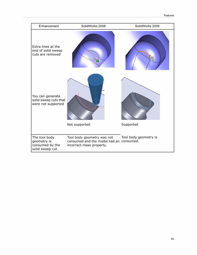
SolidWorks 2009SolidWorks 2008Enhancement
Extra lines at theend of solid sweepcuts are removed
SupportedNot supported
You can generatesolid sweep cuts thatwere not supported
Tool body geometry isconsumed.
Tool body geometry was notconsumed and the model had anincorrect mass property.
The tool bodygeometry isconsumed by thesolid sweep cut.
50
Features

5Parts
This chapter includes the following topics:
• Dual Dimensions for Measurement Results• Dimensions in Mirrored and Derived Parts• Custom and Default File Properties in Equations• Changing Parts Display Characteristics• Reattach Derived Parts• Custom Properties Assigned to Parts• Sensors• Mold Design• Sheet Metal• Weldments
Dual Dimensions for Measurement ResultsYou can configure theMeasure tool to display results using two different units of measure.For example, you can specify both millimeters and inches for display in the Measuredialog box, measurement callouts, and the status bar.
To use dual dimensions:
51

1. Click Measure (Tools toolbar) or Tools > Measure.
2. In the Measure dialog box, click Units/Precision .3. In theMeasure Units/Precision dialog box, select Use custom settings and select
the first length unit.
If you select Use document settings, dual units are only shown if you haveenabled dual units on the Document Properties tab of the Options dialogbox.
4. Click Use Dual Units and select the second unit.
5. Click .
Dimensions in Mirrored and Derived PartsWhen you create a mirrored or derived part, you can import the sketch and featuredimensions of the original part. While these dimensions are not editable, they can beused in drawings created from the mirrored or derived part.
To import dimensions when you mirror or derive a part, select Model dimensions in theInsert Part PropertyManager.
Original part showing sketch dimension
Mirrored part showing imported dimensions
Drawing based on mirrored part
52
Parts
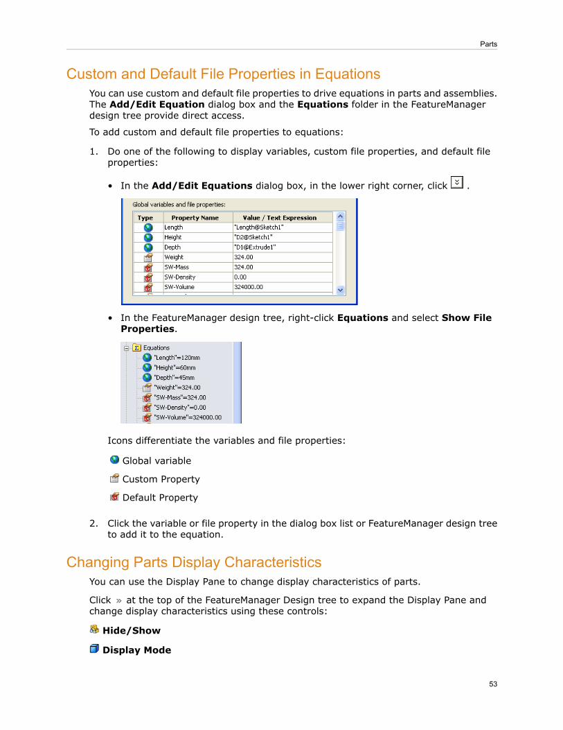
Custom and Default File Properties in EquationsYou can use custom and default file properties to drive equations in parts and assemblies.The Add/Edit Equation dialog box and the Equations folder in the FeatureManagerdesign tree provide direct access.
To add custom and default file properties to equations:
1. Do one of the following to display variables, custom file properties, and default fileproperties:
• In the Add/Edit Equations dialog box, in the lower right corner, click .
• In the FeatureManager design tree, right-click Equations and select Show FileProperties.
Icons differentiate the variables and file properties:
Global variable
Custom Property
Default Property
2. Click the variable or file property in the dialog box list or FeatureManager design treeto add it to the equation.
Changing Parts Display CharacteristicsYou can use the Display Pane to change display characteristics of parts.
Click at the top of the FeatureManager Design tree to expand the Display Pane andchange display characteristics using these controls:
Hide/Show
Display Mode
53
Parts

Appearance
Transparency
For all parts, you can change the appearance (material and color) and transparency ofselected features of the part.
For multibody parts, you can also change the hide/show state and display mode (forexample, Shaded, Hidden Lines Visible, Wireframe) of a selected body.
Reattach Derived PartsThe functionality of the Split feature has been expanded.
New functions include:
• Reattach of existing files while editing the Split feature.• The option to automatically reattach parts when you change the trim tools.
The results of the reattach process are reported in balloon messages.
• Shortened callouts for better readability.
Tooltips provide the full path.
• An Attach File dialog box that lets you reattach existing derived parts that are relatedto the split feature. Visual previews help you identify parts.
You can also specify new names for derived parts.
The Save All Bodies button has been renamed to Auto-Assign Names. You stilluse this control to assign new part names to unassigned bodies created when youcut the part.
54
Parts

You can reattach derived parts to:
• A specified stock part file• Specific bodies in the stock part file
Stock part split by a sketch
Reattaching Existing Derived PartsWhen you edit a split part feature, you can reattach the resultant bodies to existingderived parts. You can select to attempt to reattach the bodies automatically. When abody cannot be reattached automatically, the Assign File dialog box lets you select thepart to which to attach the body.
To reattach derived parts:
1. Open Parts\Split-part.SLDPRT.
2. In the FeatureManager design tree, right-click the Split1 feature and click EditFeature .
3. In the PropertyManager, under Trim Tools, clear Sketch3 and select Sketch4 asthe trim tool to which to reattach parts.
4. Click Cut Part.5. When prompted to attach split bodies to existing files, click Yes.
A message reports the result. In this case, some, but not all of the bodies arereattached.
The software attempts to match parts with bodies using internal information.Changes made to the model may cause unintended results. Always inspect theresults to make sure they are correct.
6. Click the callout for Body 2, the body that was not reattached.7. In the Assign File dialog box, select Existing File.8. Use the drop-down list to select bodya.sldprt, which was not automatically reattached.
A preview shows the part.
9. Click OK in the dialog box, and then click in the PropertyManager.
Reattaching Parts When You Change Trim ToolsWhen you change Trim tools, you can create new parts as well as reattach existing parts,for example, when the number of bodies created with the new trim tool is greater thanthe number of existing parts.
55
Parts

To reattach parts when you change trim tools:
1. Open Parts\Split-part2.SLDPRT.
2. In the FeatureManager design tree, right-click the Split1 feature and click EditFeature .
3. In the PropertyManager, under Trim Tools, clear Right Plane and select Sketch3as the new trim tool.
4. Click Cut Part.5. When prompted to attach split bodies to existing files, click Yes.
A message reports that some of the bodies have been reattached.6. Click the callout for Body 3, the body that has not been reattached.
In the Assign File dialog box, both files listed in the Existing Files drop-down listhave already been reattached.
7. Select New file, and then click the Browse button to open the Save As dialog box.8. Type Middle as the name of the derived part and click Save.
9. Click .
Custom Properties Assigned to PartsYou can assign custom and configuration-specific properties from the new Custom
Properties tab in the Task Pane.
See Custom Properties on page 15.
SensorsSensors monitor selected properties in parts and assemblies and alert you when valuesdeviate from the limits you specify.
See Sensors on page 74.
Mold Design
Analysis Tools
Analysis tools can now run continuously and report changes as the model is changed.The analysis tools are:
• Draft Analysis. Enhancement of the previous Draft Analysis tool.• Undercut Analysis. Enhancement of the previous Undercut Detection tool.• Parting Line Analysis. New tool to analyze potential parting lines as you designmolded parts.
You still need to use Parting Line (Mold Tools toolbar) to add a parting linefeature.
After running an analysis:
• You can turn the display of the results on and off, similar to Zebra Stripes.
56
Parts

• The results update dynamically when the geometry of the part changes.
Display of draft analysis results:
Sheet Metal
Convert to Sheet MetalYou can convert a solid or surface body into a sheet metal part using the Convert toSheet Metal command. The solid body can be an imported sheet metal body.
After you create the part, you can apply all sheet metal features to it.
Use the Convert to Sheet Metal command with:
• Solid or surface bodies that have:
• No shells or fillets• Either a shell or fillets• Both a shell and fillets
• Imported parts that are already in the form of a sheet metal part
Sheet metal part with bends highlightedSolid part
57
Parts

Sheet metal part flattened
Converting a Solid Part to a Sheet Metal PartYou use the Solid to Sheet Metal PropertyManager to specify the thickness and defaultbend radius for the part. When you select the bend edges, the required rips edges areselected automatically so that the completed part can be flattened.
To convert a solid part to a sheet metal part:
1. Open SheetMetal\Solid_to_SM.SLDPRT.
2. Click Convert to Sheet Metal (Sheet Metal toolbar) or Insert > Sheet Metal> Convert To Sheet Metal.
3. In the PropertyManager:a) Under Sheet Metal Parameters, select the top face as the fixed face for the sheet
metal part.
b) Set the sheet thickness to 1mm and the bend radius to 2mm.c) Select Reverse Thickness.d) Under Bend Edges, select the edges of the top face as bend edges, then continue
selecting the edges that are parallel to the one highlighted below. Select a totalof 12 edges.
Changing the display style to Hidden Lines Visible makes it easier to see allbend edges.
58
Parts
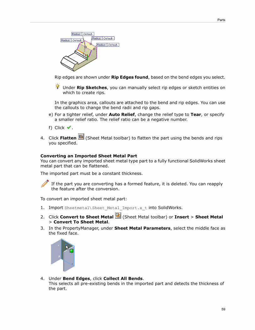
Rip edges are shown under Rip Edges found, based on the bend edges you select.
Under Rip Sketches, you can manually select rip edges or sketch entities onwhich to create rips.
In the graphics area, callouts are attached to the bend and rip edges. You can usethe callouts to change the bend radii and rip gaps.
e) For a tighter relief, under Auto Relief, change the relief type to Tear, or specifya smaller relief ratio. The relief ratio can be a negative number.
f) Click .
4. Click Flatten (Sheet Metal toolbar) to flatten the part using the bends and ripsyou specified.
Converting an Imported Sheet Metal PartYou can convert any imported sheet metal type part to a fully functional SolidWorks sheetmetal part that can be flattened.
The imported part must be a constant thickness.
If the part you are converting has a formed feature, it is deleted. You can reapplythe feature after the conversion.
To convert an imported sheet metal part:
1. Import Sheetmetal\Sheet_Metal_Import.x_t into SolidWorks.
2. Click Convert to Sheet Metal (Sheet Metal toolbar) or Insert > Sheet Metal> Convert To Sheet Metal.
3. In the PropertyManager, under Sheet Metal Parameters, select the middle face asthe fixed face.
4. Under Bend Edges, click Collect All Bends.This selects all pre-existing bends in the imported part and detects the thickness ofthe part.
59
Parts

You can also manually select bend edges.
5. Click .
Converting Using Rip SketchesWhen a rip is required to create a sheet metal part, you can use 2D and 3D sketches todefine the rip. You must create the sketch before converting the solid body to a sheetmetal part.
To use a rip sketch when converting a solid body:
1. Open the part.
2. Click Convert to Sheet Metal (Sheet Metal toolbar) or Insert > Sheet Metal> Convert To Sheet Metal.
3. In the PropertyManager, under Sheet Metal Parameters, select the fixed face.4. Under Bend Edges, select the bend edges.5. Under Rip Sketches, select the sketch you created to define the rip.
6. Click .
Expanded Sheet Metal Gauge/Bend TableThe sheet metal gauge table has been expanded to let you associate a bend allowance,bend radius, or k-factor with any combination of thickness (gauge), bend radius, andmaterial.
The sheet metal gauge tables and bend tables have been combined so that both gaugetable and bend table values can be read into the Sheet Metal Gauges PropertyManager.
You can still use gauge tables and bend tables that have the old format. Only old-stylebend tables can be read into the Bend Table dialog box.
The Gauge No., Thickness, and Radius values in the new tables populate thecorresponding fields in theSheet Metal Gauges PropertyManager.
The value in the Angle column is fed into the Angle drop-down list in the Edge FlangePropertyManager.
To edit the new gauge/bend tables click Edit > Bend Table > Edit Table.
To use the new gauge tables:
1. Right-click a sheet metal part and click Edit Feature .
60
Parts

2. In the PropertyManager, under Sheet Metal Gauges, select Use gauge table.
3. Select a new format gauge table by using the drop-down list or browsing to it.
4. Under Sheet Metal Parameters, select the gauge.The thickness and radius are calculated from the table. You can override these values.
5. Under Bend Allowance, you can use the drop-down list to select the type of bendcalculation to use (K-Factor, Bend Allowance, or Bend Deduction) or to switchfrom the gauge table to an old-style bend table.
6. Click .
Beveled/Chamfered Edges with Sheet MetalSolidWorks maintains bevels and chamfers while you work with sheet metal parts.
Beveled and chamfered edges are now maintained when you:
• Flatten cylindrical sheet metal parts
Cylinder flattenedCylinder with countersunk hole
• Flatten a part with a chamfer along an edge that traverses a bend
Part flattenedChamfer across bend
• Use other sheet metal commands like Sketched Bend, Jog, and Hem• Insert bends into parts with bevels or chamfers
61
Parts

The bevels or chamfers cannot be on an edge that intersects a bend.
Chamfers and bevels are only maintained when the sheet metal parts are createdin SolidWorks 2009.
Cross BreaksYou can add a cross break to a sheet metal part such as a duct to stiffen it, deflect water,etc.
Cross break characteristics:
• You can flatten sheet metal parts with cross breaks.• You can add an edge flange or miter flange to the edge of a face with a cross break.
The corners of the cross break must be at the ends of the edge.
• When you add a cross break, the part's dimensions are not changed.• You can edit the cross break sketch to move corners and change relationships.• When you create a drawing from a part with a cross break, the flattened view is labeledwith the bend direction, bend radius, and bend angle.
Drawing of part, showingcross break labels
Flattened partSheet metal part withcross break
The cross break is a graphical representation, not a geometric entity.
To add a cross break to a sheet metal surface:
1. Click Cross Break (Sheet Metal toolbar) or Insert > Sheet Metal > CrossBreak.
2. In the PropertyManager, select:
• The face on which to create the cross break• The direction of the cross break• The break radius• The break angle
3. Click .
62
Parts

Weldments
GroupsYou can now define a weldment group, a collection of related segments in a structuralmember. Configure a group to affect all its segments without affecting other segmentsor groups in the structural member.
You can define a group in a single plane or in multiple planes. A group can contain oneor more segments. A structural member can contain one or more groups.
Types of groups are:
A continuous contour of segments joinedend-to-end. The end point of the group canoptionally connect to its beginning point.
Contiguous
A discontinuous collection of parallelsegments. Segments in the group cannottouch each other.
Parallel
When you define a group, the second segment you select determines the group type. Tocreate a contiguous group, select two connecting segments. To create a parallel group,select two parallel segments.
After you define a group, you can operate on it as a single unit. You can:
• Specify the corner treatment for the segments in the group.• Create weld gaps between segments to allow space for weld beads.• Mirror the profile of a single group.• Align a group without affecting the rest of the structural member.
Working With Groups
To work with groups:
1. Open Weldments\weldment_groups.sldprt.
2. Configure the structural member:
a) Click Structural Member (Weldments toolbar) or Insert > Weldments >Structural Member.
b) Pin the PropertyManager.c) Under Selections:
• Select ansi inch in Standard.• Select c channel in Type.• Select 3 x 5 in Size.
3. Create groups:
63
Parts

Create Group1 by selecting the highlighted segments:a)
To create a contiguous group, ensure that the second segment you selectconnects to the first.
b) Click New group to create Group2 from the highlighted segments:
c) To create Group3, right-click, select Create New Group, and select the highlightedsegments:
d) In Groups, select each group.In turn, their segments are highlighted in the graphics area and their segmentnames are listed in Path segments under Settings.
4. Apply corner treatments and create weld gaps for Group1:
A weld gap provides space for a weld bead without requiring you to shorten thesegments.
a) In Groups, select Group1.
b) Select Apply corner treatment and click End Miter .
c) Set Gap between Connected Segments in Same Group to 10 and pressTab.
Use Gap between Different Group Segments to control the gap atintersections with other groups.
64
Parts

d) Zoom to the lower left corner of Group1 to see the mitered corner with a weld gap.The changes you made affect Group1 only.
5. Override the corner treatment for the lower-left corner:a) Click the corner.
b) In the dialog box, select Set corner specific weld gaps.
c) Set Gap between Connected Segments in Same Group to 2.
d) Click .e) Inspect the other corners of Group1 to compare their weld gaps.
6. Set the view orientation to Trimetric .Note that the channels in Group2 point inward.
7. Mirror the profile of Group2:a) In Groups, select Group2.b) Under Settings, select Mirror Profile.c) Select Vertical Axis.
The channels now point outward.
8. Rotate one group without rotating the entire structural member:a) In Groups, select Group3.b) Under Settings, set Rotation Angle to 45 and press Tab.c) Rotate the model to verify that members of Group3 are at an angle, while other
groups are unaffected.
9. Unpin the PropertyManager and click .
Working with Enhanced Trim and Extend ToolThe trim and extend tool splits a structural member that is crossed by another structuralmember. You can also specify a weld gap between the structures, keep or discard eithersplit side, or extend a structure.
To work with the enhanced tool:
1. Open Weldments\wld-trim-extend.sldprt.
65
Parts

2. Click Trim/Extend (Weldments toolbar) or Insert > Weldments >Trim/Extend.
3. Under Corner Type, click End Trim .4. Select Structural Member2 and Structural Member3 for Bodies to be Trimmed.5. Under Trimming Boundary:
a) Select Bodies.b) Select Structural Member4 for Face/Bodies.
c) Select Weld Gap and set Weld Trim Gap to 8.The structures are trimmed with a visible gap. Callouts let you keep or discardbodies.
6. Click keep on one callout to toggle to discard.Preview mode shows which structures to retain or delete.
7. Pin the PropertyManager and click .In place of the body you discarded, you see its sketch line.
8. Extend the top structure:a) Rotate the model so you can see the inner face of the right side.b) Select Structural Member1 for Bodies to be Trimmed.c) Under Trimming Boundary, click Face/Plane.d) Select the inside face of Structural Member5 for Face/Bodies.
9. Click .The body extends across the model.
Creating Gussets with ChamfersYou can create a gusset with a chamfer that allows room for a weld bead under the gusset.
66
Parts

Gusset with chamferGusset without chamfer
To create a gusset with a chamfer:
1. Open Weldments\gusset-sample.sldprt.
2. In the FeatureManager design tree, right-click Gusset1 and select Edit Feature .3. In the PropertyManager, under Profile, click Chamfer.
.
4. Set the height, Chamfer Distance5, to 30.
5. Set the width, Chamfer Distance6, to 50.
You can specify the chamfer width (d6) or the chamfer angle (a2).
6. Click .
End Caps
Enhancements:
• You can now simultaneously add end caps to multiple faces at the same time. In the
End Cap PropertyManager, add multiple faces to Face .• When you add an end cap, you can now project it inward, retaining the original lengthof the structure. Previously, you could project the end cap outward only, which extendedthe length of the structure.
In the End Cap PropertyManager for Thickness direction, select:
67
Parts

Inward (New)Outward
BOMs and WeldmentsYou can include detailed weldment cut lists in indented BOMs and you can insert the BOMsin weldment part files.
For more information, see Detailed Weldment Cut Lists in BOMs on page 90.
68
Parts

6Assemblies
This chapter includes the following topics:
• General• Large Assemblies• Assembly Features in Parts• Bills of Materials in Assembly Documents• Clearance Verification• Hinge Mates• Sensors• SpeedPak
General
Custom Properties
You can assign custom and configuration-specific properties from the new Custom
Properties tab in the Task Pane. See Custom Properties on page 15.
Design ClipartYou can now add Design Clipart in assemblies.
Entities you can add as assembly features include:
• Sketches• Features that remove material
Entities you can add while in Edit Component mode include:
• Sketches• Features that add or remove material.
Equations
You can use custom and default file properties to drive equations in parts and assemblies.The Add/Edit Equation dialog box and the Equations folder in the FeatureManagerdesign tree provide direct access. See Custom and Default File Properties in Equationson page 53.
Instant3D in AssembliesAssemblies now support Instant3D. You can use Instant3D to edit components within theassembly, or to edit assembly level sketches, assembly features, and mate dimensions.
See Using Instant3D in Assemblies on page 39.
69

Measurements
You can configure theMeasure tool to display results using two different units of measure.For example, you can specify both millimeters and inches for display in the Measuredialog box and measurement callouts. See Dual Dimensions for Measurement Results onpage 51.
Missing Reference Ghosting for Mates
When an entity used as a reference in a mate is missing, a ghost of the missing referenceappears in the graphics area, and a warning message appears in the PropertyManager.See Missing Reference Ghosting on page 35.
Selection Tools
Select Toolbox on the Select flyout button (Standard toolbar) selects all Toolboxcomponents in the assembly.
Large AssembliesSome enhancements are particularly useful when you work with large assemblies.
Performance
Enhancements have been made to improve performance for very large and complexassemblies. Commands with improved performance include:
• Window selection• Copying and adding sub-components• Deleting sub-assemblies• Saving assemblies• Adding mates• Editing parts
When working in drawings of very large and complex assemblies, commands with improvedperformance include:
• Panning and zooming• Inserting and selecting dimensions• Adding and switching sheets• Inserting views (initial, projected, section, and detail views)• Switching from the drawing to the assembly and back• Creating a drawing from the assembly• Changing the view to shaded
The performance improvements listed above are most noticeable in very large andcomplex assemblies.
Assemblies Larger than One Kilometer
You can now create assemblies that are larger than one kilometer. Though individualparts must still be smaller than one kilometer (1000m; ~3280 feet; ~39,370 inches),you can assemble parts such that the overall size of the assembly exceeds one kilometer.
70
Assemblies

Mate References in Lightweight Assemblies
Mate references are now supported in lightweight assemblies. Previously, the componentcontaining the mate reference needed to be resolved for the mate reference to work.
Motion Studies in Lightweight AssembliesYou can run motion studies for assemblies in lightweight mode. You do not have to resolvea large assembly before running a motion study.
SpeedPak
SpeedPak creates a simplified representation of an assembly without losing references.If you work with very large and complex assemblies, using SpeedPak can significantlyimprove performance while working in the assembly and its drawing. See SpeedPak onpage 75.
Unloading Hidden ComponentsYou can unload hidden components from memory but retain the effects of their mates.
To unload hidden components, right-click the assembly icon at the top of theFeatureManager design tree and select Unload Hidden Components. The componentsare unloaded from memory and are not visible, but the effects of their mates are retained.In SolidWorks 2008, you could use Quick view / Selective open while opening anassembly, to load only visible components, leaving hidden components unloaded. Nowyou can unload hidden components after the assembly is open.
Assembly Features in PartsYou can propagate assembly features into the parts they affect. Features you canpropagate include:
• Hole Wizard holes• Simple holes• Extruded cuts• Revolved cuts
If you pattern the features in the assembly, the pattern feature also propagates to thepart file.
Select Propagate feature to parts in the Feature Scope section of the PropertyManagerwhen you create the feature in the assembly. Otherwise, the feature appears only in theassembly and not in the part.
In the part, external references to the assembly feature are created, and the featureappears at the bottom of the part's FeatureManager design tree. For sketch-based features,a derived sketch is created in the part as well.
You edit the feature in the context of the assembly. If you want to edit the feature fromwithin the part document, you must first break the external references.
In the part document, you can right-click the feature and select Make Independentto break the reference.
71
Assemblies

Bills of Materials in Assembly DocumentsYou can create bills of materials (BOMs) in assembly files. You no longer need to createa drawing first.
Create a BOM in an assembly or part by clicking Insert > Tables > Bill of Materials.After setting parameters in the PropertyManager, click in the graphics area to place theBOM.
BOMs appear in the Tables folder in the FeatureManager design tree. The name of theconfiguration to which a BOM applies appears beside the BOM feature.
Working with Assembly BOMsYou can edit a BOM in the assembly just as you would in a drawing.
You can edit a BOM in a separate window. In the FeatureManager design tree, right-clickthe BOM and select Show Table in NewWindow. When you close the window, the BOMreturns to the graphics area of the assembly.
You can right-click a BOM to:
• Print it• Select Save As and export to these formats:
• Template (.sldbomtbt)• Excel (.xls)• Text (.txt)• Comma-separated values (.csv)• Drawing interchange format (.dxf)• Drawing (.dwg)• eDrawings (.edrw)• Portable document format (.pdf)
After creating an assembly BOM and saving the assembly, you can insert the BOM intoa referenced drawing. See Copying Assembly BOMs into Referenced Drawings on page88.
The BOM in the drawing is not linked to the BOM in the assembly.
The balloon status column is not supported in BOMs in assembly files.
72
Assemblies

Clearance VerificationWith Clearance Verification, you can check the clearance between selected componentsin assemblies. The software checks the minimum distance between the components andreports clearances that fail to meet the minimum acceptable clearance you specify.
You can select entire components or particular faces of components. You can checkbetween just the selected components, or between selected components and the rest ofthe assembly.
To check clearance, click Clearance Verification (Assembly toolbar) or Tools >Clearance Verification. The tool works in a manner similar to Interference Detection.To display a clearance failure in the graphics area, select it in Results in thePropertyManager.
Hinge MatesA hinge mate limits the movement between two components to one rotational degree offreedom. It has the same effect as adding a concentric mate plus a coincident mate. Youcan also limit the angular movement between the two components.
Advantages of hinge mates:
• When modeling, you need to apply only one mate, where otherwise you would haveapplied two.
• If you run an analysis (such as with SolidWorks Simulation), the reaction forces andresults are associated with the hinge mate, not one particular concentric or coincidentmate.
To add a hinge mate:
1. Open Assemblies\hinge_mate.sldasm.
2. Click Mate (Assembly toolbar).
3. In the PropertyManager, under Mechanical Mates, click Hinge .4. Under Mate Selections:
a) For Concentric Selections, select the two cylindrical faces as shown.
b) For Coincident Selections, select the two planar faces as shown.
73
Assemblies
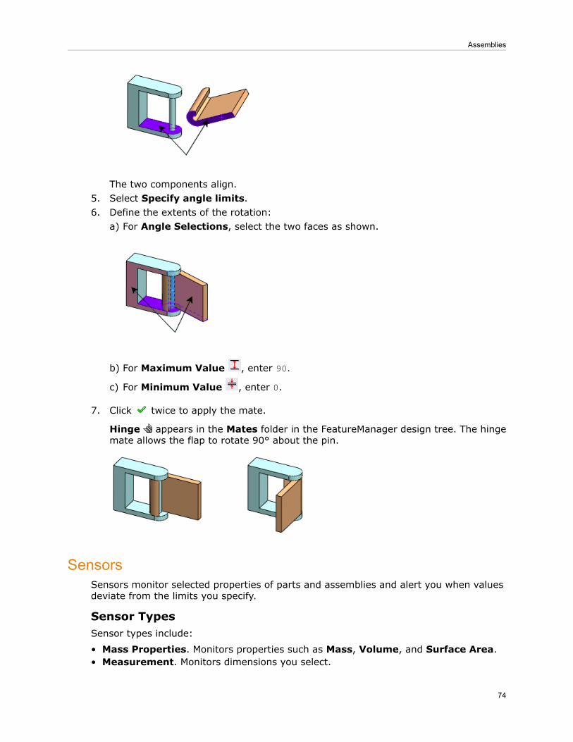
The two components align.5. Select Specify angle limits.6. Define the extents of the rotation:
a) For Angle Selections, select the two faces as shown.
b) For Maximum Value , enter 90.
c) For Minimum Value , enter 0.
7. Click twice to apply the mate.
Hinge appears in the Mates folder in the FeatureManager design tree. The hingemate allows the flap to rotate 90° about the pin.
SensorsSensors monitor selected properties of parts and assemblies and alert you when valuesdeviate from the limits you specify.
Sensor TypesSensor types include:
• Mass Properties. Monitors properties such as Mass, Volume, and Surface Area.• Measurement. Monitors dimensions you select.
74
Assemblies

• Interference Detection. (Available in assemblies only.) Monitors the assembly forinterferences between components you select.
• Simulation Data. (Available in parts and assemblies, for use in SolidWorks Simulation.)Monitors data such as Stress, Strain, Displacement, etc.
For more information about Simulation Data sensors, see Sensors on page 112.
Creating Sensors
To create a sensor, right-click the Sensors folder in the FeatureManager design tree,select Add Sensor, and set parameters in the PropertyManager. Optionally, you can setan alert to notify you immediately when the sensor value deviates from the limits youspecify.
NotificationsNotifications appear at specified intervals to notify you about:
• Sensors that have triggered alerts• Sensors that are out of date
To change the notification intervals, right-click the Sensors folder in the FeatureManagerdesign tree, select Notifications, and set parameters in the PropertyManager.
SpeedPakSpeedPak creates a simplified representation of an assembly without losing references.If you work with very large and complex assemblies, using SpeedPak can significantlyimprove performance while working in the assembly and its drawing.
Use SpeedPak when you want to insert a complex large assembly into a higher levelassembly. A SpeedPak is essentially a subset of the parts and faces of an assembly, whichyou create in the ConfigurationManager. Unlike regular configurations, where you cansimplify an assembly only by suppressing components, SpeedPak simplifies withoutsuppressing. Therefore, you can substitute a SpeedPak for the full assembly in higherlevel assemblies without losing references. Because only a subset of the parts and facesis used, memory usage is reduced, which can increase performance of many operations.
Creating a SpeedPak
For simplicity, a small assembly is used in this example. However, improvementsin assembly performance due to SpeedPak are most noticeable in very large andcomplex assemblies.
To create a SpeedPak:
1. Open Assemblies\computer_assembly\power supply assembly.sldasm.
2. On the ConfigurationManager tab , under Configurations, right-click Defaultand select Add SpeedPak.
3. In the PropertyManager:
a) For Faces to Include , select the front, bottom, and back faces of the chassis.
75
Assemblies

BackBottomFront
b) For Bodies to Include , select the connector.
c) Click .A configuration named Default_speedpak is created as a child of Default.
4. Move the pointer over the assembly.In the region surrounding the pointer, only the faces and body you selected for theSpeedPak are visible.
Assembly with pointerAssembly without pointer
To see the behavior described in step 4, make sure the driver for your graphicscard is up to date. Seehttp://www.solidworks.com/pages/services/VideoCardTesting.html.
76
Assemblies

5. Click the FeatureManager tab .No components appear in the FeatureManager design tree. Note the SpeedPakassembly icon at the top of the tree.
6. Save the assembly.
Inserting a SpeedPak
To insert a SpeedPak:
1. Open Assemblies\computer_assembly\computer01.sldasm.
2. Click Insert > Component > Existing Part/Assembly.3. In the PropertyManager:
a) Under Part/Assembly to Insert, select power supply assembly.b) Click anywhere in the graphics area to insert the assembly.In the region surrounding the pointer, only the faces and body you selected for theSpeedPak are visible. They are the only items you can select for operations such asmating.
When you use SpeedPak configurations in drawings, you can only dimensionsto edges included in the SpeedPak.
77
Assemblies

7Motion Studies
This chapter includes the following topics:
• General• Design Library for Motion Elements• Redundant Constraint Force Results• Motion for Layout Sketches• Mates
General
Name ChangesThe COSMOSMotion™ add-in name is changed to SolidWorks Motion.
Names of study type are also changed.
New Study Type NameOld Study Type Name
Motion AnalysisCOSMOSMotion
Basic MotionPhysical Simulation
AnimationAssembly Motion
These name changes affect the corresponding property headings in the Motion StudyProperties PropertyManager.
Lightweight Assembly SupportYou can run motion studies for assemblies in lightweight mode. You do not have to resolvea large assembly before running a motion study.
Configuration-specific Motion StudiesYou can calculate motion study results for different model configurations.
To obtain results for two configurations:
1. Calculate a motion study for one configuration and plot the results.2. Switch to the other configuration.
3. Click Play from Start to update the configuration-specific results.
Design Library for Motion ElementsYou can save motion elements such as springs, motors, or force specifications for reusein other models.
78

Add motion elements to the Design Library as you would add other items. All motionelements in the Design Library are saved with the .sldsimfvt extension.
While in any motion study, drag saved motion elements from the Design Library to yourmodel.
Redundant Constraint Force ResultsAs in previous releases, aMotion Analysis study eliminates redundant constraints whencalculating motion. This results in a calculation of zero force at the mate locations of theaffected parts. For models with redundant constraints due to mates, you can haveSolidWorks Motion automatically replace these mates with bushings. Forces are thencalculated at the locations of the redundant mates.
These redundant contraint options available in previous releases are now obsolete:
• Make all mates flexible.• Replace redundant constraints with bushings, available by clicking AdvancedOptions.
To address redundant constraints, now you can select Replace redundant mates withbushings under Motion Analysis in the Motion Studies Properties PropertyManagerbefore running the study. This leads to better force results in most cases.
You can edit the overall bushing stiffness and damping values used in the motionstudy by clicking Bushing Parameters from the Motion Study PropertiesPropertyManager.
Motion for Layout SketchesYou can now run Animation and Motion Analysis motion studies for layout sketchmechanisms you create from sketch blocks.
Motion Analysis studies require values for the mass, center of mass, and momentsof inertia for each block in the layout sketch. Estimated values for mass and momentsof inertia are assigned to each block, based on a uniform steel block. The defaultvalue for the center of mass is at the center of the block.
For each block in the layout sketch, you can modify the component mass propertiesby editingMass Properties in the Block PropertyManager before running aMotionAnalysis study.
You cannot edit the mass properties for a layout sketch motion study unless youselect Motion Analysis for the motion study type.
79
Motion Studies

Example: Layout Sketch for a Crane
Run a Motion Analysis study on a two-dimensional layout sketch:
1. Open Motion Studies\Crane_Layout.sldasm and select the MotionStudy tab.
The layout sketch consists of connected blocks. The blocks arelisted in the FeatureManager design tree and in theMotionManager tree.
2. Click the force in the MotionManager design tree.
The force is applied at the piston.
3. Click Layout (Layout Tools toolbar).4. Select the upper arm block in the layout sketch in the graphics area.5. Scroll to Mass Properties in the upper arm Block PropertyManager.
The default mass value is estimated. You can edit the mass,change the center of mass location, or edit moments of inertia.
6. Click and to close the layout sketch.
7. Click Play from Start to view the motion.
Mates
Path MatesYou can now include path mates in Motion Analysis studies.
To constrain assembly component motion to a path:
1. Select Insert > Mate .2. Define a path mate for components.3. Select the Motion Study tab, and select Motion Analysis for Type of Study.4. Include motion study elements as necessary.
You must include a Motor , a Force , or Gravity to force the motion.
5. Run the study.
80
Motion Studies

Example: Path Mate Motion Study with Gravity
1. Open Motion Studies\MazeGame.sldasm.2. Select the Motion Study tab.
3. Click Play from Start .
Game at the start of the study:
• The path mate follows a path along the channels defined by the maze.• The ball, forced by gravity, is set to follow the path defined by thepath mate.
Mate Location PointsSolidWorks Motion studies use mate location points to determine how parts move inrelation to each other. You can now modify the mate location used for motion studies.
You can override default location points by selecting Mate location from the Analysistab of the Mate PropertyManager.
Specifying the Mate Location
To modify the mate location:
1. Select Insert > Mate to create a new mate or edit a selected mate.2. Select the Analysis tab of the Mate PropertyManager.
3. Select the Mate location field and select a point on the model for the matelocation.
The mate location is always a point. If you select another type of entity such asa face for the mate location, the mate location is at the center of the selectedentity.
4. Click .
81
Motion Studies

Motion Study-specific MatesMotion study-specific mates are mates you create for a motion study that are independentof the assembly model mates. Using the new motion study-specific mates, you can nowcreate multiple motion studies to analyze model motion with different mates withoutchanging the model.
To create motion study-specific mates:
1. Select a motion study.2. Add mates to the assembly from the motion study.
Motion study-specific mates are listed only on theMotionManager design tree. Thestring Local prefaces the name of motion study-specific mates.
To see that the motion study-specific mates are not part of the assembly model, viewthe assembly mates from the Model tab.
82
Motion Studies

Example: Working with Study-specific Mates
The model in this example includes four motion studies.
Each motion study:
• Starts with a wrench assembly.• Adds a distance mate to the wrench screw within the motion study.
The distance mate determines how far the screw can turn.
• Adds a force at the wrench handle.
Each motion study uses a different distance mate. Calculate the motionfor each study to find the distance required to make the wrench close:
1. Open Motion Studies\Wrench.sldasm
2. Select the MotionStudy2_Distance=0.6in motion study.3. Expand the mates in the FeatureManager design tree.
These original model mates do not include a distance mate.
4. Expand the mates in the MotionManager design tree.
Notice the distance mate LocalDistance7, defining how far the screwcan turn to adjust the wrench handle and jaw positions as you forcethe handle.
5. Right-click the distance mate and select Edit Feature to view thedistance mate parameters.
For this study, the mate distance is set to 0.6 inch. This distance mateis not part of the original assembly mate group and is relevant onlyto this motion study.
6. Click Play from Start to view the motion.
The wrench does not close all the way.
7. Select the other motion study tabs to view this experiment withdifferent distance mate values. Each study has a different mate
83
Motion Studies

distance value, but none of the studies change the original modelmates.
8. Calculate the final motion study with a mate distance of 1.0 inch tosee the wrench close.
84
Motion Studies

8Drawings and Detailing
This chapter includes the following topics:
• Customized Drafting Standards• Bills of Materials (BOMs)• Detail Positioning• Print Options for Drawings• Title Blocks in Drawing Sheets• Favorites are Renamed to Style• Format Painter• Detailing for Sketch Slots• General
Customized Drafting StandardsDetailing document properties include specifications for dimensions, annotations, andtables. A drafting standard includes a set of detailing document properties that you canuse with multiple drawings. You can now create and customize drafting standards for adrawing document.
You can:
• Save drafting standards to a file, archive them, and send them to others.• Import drafting standards from a saved standards file.• Save custom standard settings to drawing templates.• Rename, copy, or delete custom standards.
You can create customized drafting standards by clicking Options (Standard toolbar)and then selecting Document Properties.
Custom settings for document properties include:
• Base detail and overall drafting standards• Customized drafting settings for each detail type• Document-level layer defaults• Custom leader and frame style and thickness• Preview images for each detail type
The overall drafting standard is saved under a modified name to prevent overwritinga fixed standard when you:
• Select one of the fixed overall drafting standards such as ANSI or ISO.• Modify a detailing document property.
85

Customizing the Drafting Standard
For this example, the drafting standard requirements for your companyare:
• Overall drafting standard: ANSI• Base standard for weld symbols: GB• Leader thickness for all annotations and dimensions: 0.20mm
To set up these requirements:
1. Click Options (Standard toolbar).2. From the Document Properties tab, select Drafting Standard.3. Select ANSI for the Overall Drafting Standard.4. Select Annotations > Weld Symbols and select GB for the Baseweld symbol standard.
5. For each annotation and dimension type, select Custom Size forLeader Thickness and type 0.20mm.
6. Select Drafting Standard and click Save to External File.7. After selecting the necessary directory, click Save to save the .sldstd
standard file.8. Click OK.
All users can refer to a saved standard by loading it. To load asaved standard, select Drafting Standard and click Load.
Overall Drafting Standards and Base Detail StandardsYou can now specify an overall drafting standard that provides defaults for all detailingoptions. Overall drafting standards apply to all detail settings unless you derive settingsfor a particular set of details from another base detail standard.
For example, all detail settings derive defaults from the ANSI standard when you set theOverall drafting standard to ANSI. Diameter dimensions derive default settings fromthe ISO standard when you set the Base diameter dimension standard to ISO.
To select an overall standard:
1. Click Options (Standard toolbar).2. Select Drafting Standard from the Document Properties tab.3. Select an overall standard.
You can also change, load, or save the overall drafting standard.
To customize a base standard for a selected detail:
1. Click Options (Standard toolbar).2. Select the detail, such as Annotations > Balloons, from the Document Properties
tab3. Select a base standard for the detail, for example, the Base balloons standard.
86
Drawings and Detailing

A base detail standard supersedes overall drafting standard settings for the selecteddetail.
Document Layer DefaultsYou can now customize the document-level layer settings for each type of detail.
After creating layers for a drawing, you can select a different layer setting for eachdimension, annotation, table, and view label detail. For example, create two layers andassign one layer to diameter dimensions and the other to surface finish annotations. Bysetting layers for details at the document level, you do not have to switch layers in thedrawing to apply custom layers.
After you assign a document-level layer to a detail type, the detail is added to theselected layer when you add that type of detail to the drawing.
To set document-level layer defaults for a detail:
1. Create layers for a drawing in SolidWorks.
2. Click Options (Standard toolbar).3. Select a detail, such as Dimensions > Chamfer, from the Document Propertiestab.
4. Under Layer, select a layer for the detail.
You can assign document-level layers to dimensions, annotations, view labels,and tables.
Custom Line Thickness and StyleFor each drawing dimension and annotation type, you can now specify document-levelline thickness and style. You can override document-level line thickness and style settingsfor individual annotation and dimension elements when you create or edit them.
To assign line thickness or style:
1. Click Options (Standard toolbar) and select the Document Properties tab.
2. Set style and thickness for the following:
• All dimension leaders• All annotation leaders• Frames for geometric tolerances, balloons, and datums
ThicknessStyle
87
Drawings and Detailing

When setting line thickness, you can customize the thickness by selecting Customsize from the thickness list and typing a value.
Overriding Document-Level Line Thickness and StyleYou can override document-level leader and frame thickness and style settings forindividual annotations or dimensions in a drawing. To override these settings, select theentity and clear Use document display in the PropertyManager.
Detailing Previews for Document PropertiesPreview images now update as you modify document property detail settings.
Preview ImagePreview Selection
Diameter dimension text aligned with diameter
leader
Diameter dimension text aligned horizontally
All detail settings affect the preview image. For example, if you change the dimensionfont, the preview image font changes accordingly.
To view detail preview images:
1. Click Options (Standard toolbar).2. Select a detail from the Document Properties tab.
Bills of Materials (BOMs)
Copying Assembly BOMs into Referenced Drawings
You can create bills of materials (BOMs) in assembly files and multibody part files. Youno longer need to create a drawing first. See Bills of Materials in Assembly Documentson page 72. After creating a BOM in an assembly and saving the assembly, you can insertthe BOM into a referenced drawing.
To insert a BOM saved with an assembly into a referenced drawing:
1. Select Insert > Tables > Bill of Materials.
88
Drawings and Detailing

2. In BOM Options, select Copy existing table.3. Select an assembly BOM from the list.
Restructuring BOMsYou can now restructure assembly components in a BOM table without affecting theassembly structure:
• Dissolve subassemblies or weldments.• Combine all items that are identical to a selected item, such as parts or weldments inthe BOM.
• Drag items from one cell in the Assembly Structure column to another to combine likeitems or re-arrange the hierarchy.
• Display detailed weldment cut lists.
To restore restructured items, right-click a modified assembly item and selectRestore Restructured Components.
Dissolving Subassemblies or WeldmentsYou can remove individual parent components within the indented hierarchy of a BOMwhile retaining child components by dissolving items in the BOM. Right-click cells in theBOM Assembly Structure column to dissolve selected subassemblies or weldments,removing them from the BOM display.
In the indented display of BOM components,right-click the first subassembly in theBOM Assembly Structure column and selectDissolve.
The first subassembly is dissolved. Its partsmove to the bottom of the AssemblyStructure column.
Combining Like ItemsRight-click a cell in the BOM Assembly Structure column to combine the item in theselected cell with all identical items in the BOM.
89
Drawings and Detailing

In the indented display of BOM components,
right-click a washer in the firstsubassembly, and select CombineIdentical Components.
All identical washers are combined with theselected washer. Item numbers andquantities are updated
To separate combined items, right-click a combined item and clear CombineIdentical Components.
Dragging Items to Restructure the BOMYou can combine like items or rearrange items by dragging components and subassembliesin the BOM Assembly Structure column.
You can drag:
• Weldment bodies to weldment bodies or parts• Parts or assemblies to parts or bodies• Parts, bodies, or assemblies to assemblies
Detailed Weldment Cut Lists in BOMsYou can now include detailed weldment cut lists for parts and assemblies in indentedBOMs. A single BOM can contain multiple weldment cut lists. A single drawing with multipleviews can contain multiple BOMs. Each BOM can include different weldment cut lists.
To display BOMs with detailed cut lists:
1. Select Insert > Tables > Bill of Materials.2. Select Indented, and then select Detailed cut list for BOM Type.3. To display cut length information in the Length column of the BOM, select
bom-weldment cut list.sldbomtbt for Table Template.
The weldment cut information is displayed in the Description column of the BOM.
You can display the detailed cut list for indented type BOMs by right-clicking theBOM table and selecting Detailed Cut List.
When you dissolve weldments that include a detailed cut list, the detailed cut list isretained in the table.
Item NumberingYou can now select flat numbering, detailed numbering, or no numbers for items inindented BOMs. Select item numbering in the Bill of Materials PropertyManager.
90
Drawings and Detailing

Flat numbering
Detailed numbering
These new numbering options for indented assemblies replace the now obsoleteShow numbering option.
Detail Positioning
Positioning Notes
You can now position notes in the following ways:
• Specify the position of a selected note from the Note PropertyManager or select Displayon the screen from Parameters.
• After selecting Move Entities (Sketch toolbar), click the note to select it, and thenclick the final position for the note. You can also specify the change in note coordinates,or use snaps to snap a note to a new position.
• Drag notes around.• From the Text Format section of the Note PropertyManager, set the vertical alignmentof note text.
• Right-click a note and select Snap to Rectangle Center to use a rectangle to positiona note.
Specifying Note Position from X-Y Coordinates
To specify note position from its on-screen X-Y coordinates:
1. Select a note.2. From the Note PropertyManager, select Display on the screen from Parameters.
Coordinate fields appear in the graphics area.3. Modify the X-Y coordinates for the selected note in the X and Y fields that appear.4. Click away from the note to close the coordinate fields.
When you select Display on the screen in the Note PropertyManager afterselecting a note, X-Y coordinate fields appear on the drawing for all notes yousubsequently select.
91
Drawings and Detailing

Attaching Dimension Extension Lines
You can now attach dimension extension lines to sketch dimensions or drawing referencedimensions:
• Move dimension extension line endpoints to other vertices or sketch entities in drawingsby single-clicking, moving the mouse to the target location, and clicking again.
• Use the quick snap options available when you select and then right-click a dimensionextension line endpoint.
You cannot attach feature dimensions using either method.
Jogging Extension LinesYou can now right-click a linear dimension extension line and select Display Options >Jog to place a jog in the line.
The dimension extension line afterdragging a jog point
The dimension extension line afterselecting Jog
To remove a jog from a selected dimension extension line, right-clickthe line and clear Display Options > Jog.
Dimension Leader Control for Same-sized FeaturesYou can now move radial, diameter, or chamfer dimension leaders, or hole callout leadersamong same-sized features in a drawing view.
To move the dimension and hole callout leader endpoints for common features, dragleader endpoints from one feature to another.
You cannot drag dimension leaders for like features across views.
92
Drawings and Detailing

Example: Like Fillets and Holes
1. Open Detailing\PARTWITHSAMEFEATURES.slddrw.2. For the bottom view, select the fillet dimension on the left and drag
the dimension leader to the same-sized fillet on the right.
When you drag a dimension extension line to a feature of thesame size, the feature is highlighted as you hover over it.
3. For the front view, select the hole callout and drag the leader toanother hole.
93
Drawings and Detailing

Multiple Jogs for Dimensions and Callouts
You can now add multiple jogs to dimension and callout leaders from Leaders tab ofthe Dimension PropertyManager. You can also add jogs as you place a dimension orcallout by right-clicking and selecting Add jog point. Drag jog points to create the jogafter inserting the jog point.
You can add multi-jog leaders to hole callouts and to these dimension types:
• Diameter• Radial• Chamfer
Print Options for DrawingsThe Print dialog box options have been modified. You can now:
• Print zoomed selections.• Print an active drawing sheet for multi-sheet drawings.• Change the new document-level printed line thickness settings while printing by clickingLine Thickness.
In addtion, the drawing document properties now control the print thickness for lines. Toaccess the printed line thickness settings while printing, from the Print dialog box, clickLine Thickness.
Printing Drawings from Zoomed Selections
To print from a zoomed selection:
1. Zoom in on a portion of a drawing.2. Select File > Print.3. Select Current screen image on the Print dialog box.
Custom Line Thickness for Print SettingsYou can now set the line thickness used in print settings for drawing documents andtemplates from the drawing document properties.
To set the thickness of lines printed from drawings:
94
Drawings and Detailing

1. Click Options (Standard toolbar).2. Select Line Thickness from the Document Properties tab.3. Set the print line thickness for any displayed thickness setting.
You can modify the printed line thickness for a document when you print by clickingLine Thickness in the Print dialog box.
Title Blocks in Drawing Sheets
Title Block ManagementYou can now select the notes in title blocks that can be entered and changed in drawings.
When defining a title block you can:
• Specify which fields are editable by template users.• Specify a hotspot area that users click to enter title block data.
Defining or Editing Title Blocks
To define or edit a title block for use in templates:
1. Open a drawing sheet, right-click the sheet format in the FeatureManager designtree, and select Define Title Block.
If you have already defined the title block, select Edit Title Block.
2. Drag a corner to resize the rectangle laid over the title block area.
95
Drawings and Detailing

This rectangle defines the hotspot that users of the drawing click to enter data in thetitle block.
You can select a hotspot of any size.
3. Select notes in the title block.The selected notes specify the title block data that users can enter into this drawingor into a drawing created from a template based on this drawing.
4. Click arrows or to reorder selected items in the Title Block Notes list in theTitle Block PropertyManager.The note order determines the order in which notes are presented to template userswhen they tab through the fields.
5. To aid users, type informational text for each selected note in the Tooltip field.
6. Click .7. Save the drawing as a template.
Entering Title Block Data
To enter title block data in a drawing:
1. Right-click the Sheet Format > Title Block in the FeatureManager design tree, andselect Enter Title Block Data.Data fields that you can edit are highlighted.
2. Enter text for each data field.
Hover over an editable text field to view information about what text to enter.
3. Click .
96
Drawings and Detailing

Favorites are Renamed to StyleDetailing Favorites is now called Style.
Save detailing styles under Style in the following PropertyManagers:
• Note• Dimension• Weld Symbol• Surface Finish• Datum Feature *
• Datum Target *
• Balloon *
• Auto Balloon• Stacked Balloon• Center Mark *
* indicates that styles for the detail are new.
Format PainterThe Format Painter tool has been moved from SolidWorks Utilities into coreSolidWorks. All current functionality from SolidWorks Utilities is supported. Use Format
Painter to paint the properties or styles used in one annotation to another.
Format Painter supports:
• All annotation properties, such as font, leader line style, line thickness, and layer (exceptfor centerlines and center marks)
• Component line fonts in drawings• Crosshatch
Using Format Painter
In this drawing, you paint the bilateral toleranced dimension format to the other dimension.
To use Format Painter:
1. Click Format Painter (Tools toolbar) or Tools > Format Painter.2. Select the source dimension for the format.
The dimension changes color.
97
Drawings and Detailing
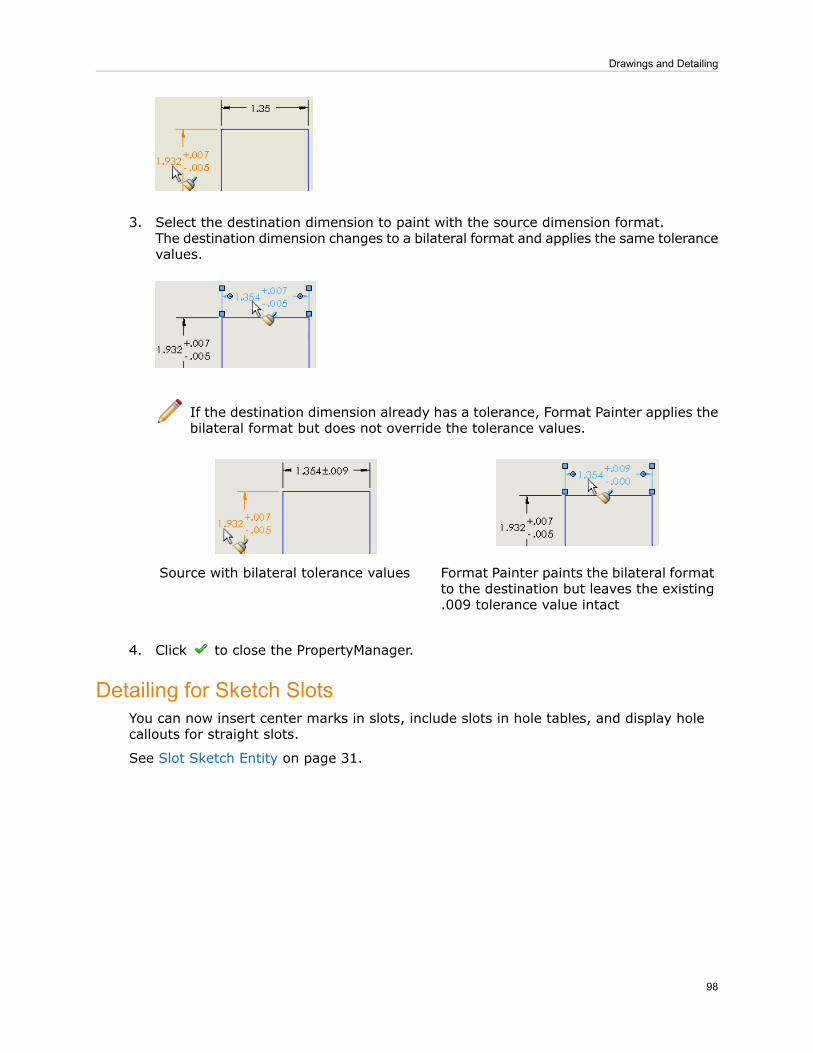
3. Select the destination dimension to paint with the source dimension format.The destination dimension changes to a bilateral format and applies the same tolerancevalues.
If the destination dimension already has a tolerance, Format Painter applies thebilateral format but does not override the tolerance values.
Format Painter paints the bilateral formatto the destination but leaves the existing.009 tolerance value intact
Source with bilateral tolerance values
4. Click to close the PropertyManager.
Detailing for Sketch SlotsYou can now insert center marks in slots, include slots in hole tables, and display holecallouts for straight slots.
See Slot Sketch Entity on page 31.
98
Drawings and Detailing

Center Marks in Slots
End-centered center marksfor an arc slot
Slot-centered center markfor an arc slot
End-centered center marksfor a straight slot
To insert center marks into slots whenever you create drawing views:
1. Click Options (Standard toolbar).2. Select the Document Properties tab.3. Select the Detailing page, and select the Center marks - slots auto-insert option.4. Select the Centerline/Center Mark page, and select the slot center mark placement
options.
The slot center mark placement options affect all center marks you place in slots,not just the ones SolidWorks places in drawing views automatically.
To manually place a center mark in a slot, select Slot center marks for Options in theCenter Mark PropertyManager.
Slots in Hole TablesYou can now include slots in hole tables:
• Slot center location appears in the XLOC and YLOC columns.• Slot dimensions for straight slots appear in the SIZE column.
Hole Callouts for SlotsYou can now apply hole callouts to straight slots. The slot dimensions appear in the callout.
General
Cancelling Long Operations for DrawingsYou can press Esc to interrupt long operations such as drawing view creation or rebuild.
You can:
• Cancel a long drawing rebuild operation to edit the drawing further before completelyrebuilding.
• Cancel long drawing view creation operations if you do not require the full drawingview.
Exporting Tables to ExcelYou can now export tables to all Excel formats., including .xlsx.
99
Drawings and Detailing

Opening Multi-sheet Drawings in Quick ViewYou can now open multi-sheet drawings quickly by viewing most sheets in Quick view,which is a read-only mode that provides a simplified drawing representation. You cannotedit sheets in Quick view. Opening sheets in Quick view can save time when openingcomplex drawings.
To open selected sheets of a multi-sheet drawing in Quick view:
1. Click File > Open.2. Browse your computer to locate a multi-sheet drawing, and click to select it.
The options for multiple sheet drawings appear.
If you double-click the drawing file, the file opens before you can set the options.
3. For Select sheets to load, select:
• Selected:
1. Select the sheet to be active when loaded.2. Press Ctrl + select one or more other sheets to fully load.
• None. Select the sheet to be active when opened in Quick view.
An asterisk appears next to the active sheet.
4. Click Open.
You must convert multi-sheet drawings from previous versions of SolidWorks toSolidWorks 2009 before you can open sheets in Quick view.
To fully load a drawing sheet that is opened in Quick view, right-click the Sheet taband select Load Sheet.
Document Properties Options Reorganization
With a drawing document open:
1. Click Options (Standard toolbar).2. Select the Document Properties tab.
The drawing document properties have been reorganized so that you can now set:
• Dimension details for each dimension type• Annotation details for each annotation type• Table details for each table type on a separate page• View label details for each view label type on a separate page
For more information, see Customized Drafting Standards on page 85.
Lightweight Assembly DrawingsWith some exceptions, assembly drawings are now loaded as lightweight.
The Lightweight option in the drawings Open dialog box is now obsolete.
100
Drawings and Detailing

9Tolerancing
This chapter includes the following topics:
• Intersect Line Features• ISO Standards Support• Orientation Constraints• Redundant Dimensions• Tangency Constraints
Intersect Line FeaturesThe Automatic Dimension Scheme tool dimensions intersect line featuresautomatically. Previously you had to dimension intersect lines manually. You also havethe option to use angle dimensions.
DimXpert for parts creates intersect line features for these cases:
Between non-perpendicular planes thatshare a common edge
Between non-perpendicular planes that havean intermediate fillet or chamfer
101

Within the features of a pocket feature,including non-perpendicular planes thathave an intermediate fillet or chamferfeature
You can have the Auto Dimension Scheme tool apply angle dimensions to planesat an angle to the datum feature. To enable angle dimensions, open a part, click Options
> Document Properties > DimXpert > Location Dimension and select Locateplanes with angle dimensions under Auto dimension scheme.
Option clearedLocate planes with angle dimensionsoption selected
ISO Standards SupportDimXpert for parts now supports ISO standards 1101 and 16792, as well as ANSI.PropertyManagers and the Display Options dialog box are modified. ANSI dimensioningand tolerancing is also enhanced.
Document Properties > DimXpert > Display Options contains these new displayoptions:
• Datum gtol attachment• Gtol linear dimension attachment• Hole callouts
The following examples illustrate the new methods for placing and attaching annotations.Although some examples show only ANSI or ISO, the methods can apply to both standards.
102
Tolerancing

Dimensions
You can dimension outside diameters and spheres using directed leaders (ANSI) anddimensions (ISO) that are attached to the surface of the feature.
ISOANSI
Hole Callouts
You can break and display hole callouts as separate dimensions or combine them. Selectthe dimension, right-click, and select Break Callout Dimension or Combine CalloutDimension. Set the defaults under Hole callouts in the Display Options dialog box.
New method (ISO)Current method (ANSI)
Datums
New attachment options include directed leaders and radial and linear dimensions.
ISOANSI
103
Tolerancing

You can attach a datum symbol to the surface of the feature, the dimension, or the
feature control frame. Click Surface or Gtol under Leader in the Datum FeaturePropertyManager. Set the defaults under Datum Gtol attachment in the DisplayOptions dialog box.
New method (ISO)Current method (ANSI)
You can add notes and symbols to datum feature symbols. Under Text, type notes toadd to the datum feature. Click More to add symbols.
Geometric Tolerances
New attachment options include radial and linear dimensions and directed leaders.
ISOANSI
104
Tolerancing

You can combine and attach the feature control frame with the size limits as shown onthe left, or attach the feature control frame and size limits separately as shown on theright. Set the defaults under Gtol linear dimension attachment in the Display Optionsdialog box.
New method (ISO)Current method (ANSI)
You can attach the feature control frame to the size limits or to the surface using a
directed leader. Click Directed Leader or Dimension under Leader in theGeometric Tolerance PropertyManager.
ISOANSI
You can add notes and symbols to feature symbols. Under Text, type notes to add tothe feature. Click More to add symbols.
Orientation ConstraintsDimXpert for parts recognizes a feature's implied vertical and horizontal constraints whenchecking its tolerance status.
105
Tolerancing

SolidWorks 2009SolidWorks 2008
The top plane is fully constrained by anintersect line and a horizontal constraint.
This part was not considered fullyconstrained. DimXpert does notrecognize that the top plane ishorizontal.
Redundant DimensionsDimXpert for parts has enhanced its handling of duplicate dimensions and tolerances.You can now combine or keep duplicate size dimensions in addition to location dimensions.Automatic dimensioning now combines dimensions where appropriate.
Combined dimensionsRedundant dimensions
Automatic Combination
Depending on how you model a part, the Automatic Dimension Scheme tool (ADS)creates separate size dimensions and tolerances even when they can be dimensioned asone.
To have the ADS tool automatically combine duplicate size dimensions and tolerances,
click Options > Document Properties > DimXpert > Display Options and selectEliminate duplicates under Redundant dimensions and tolerances.
The ADS tool then automatically combines these entities:
• Plus/Minus size dimensions• Size dimensions with geometric tolerances• Geometric tolerances
106
Tolerancing

Manual CombinationTo combine the same types of duplicates manually, Ctrl + select the dimensions in thegraphics area, right-click, and select Combine dimensions or Combine Gtol.
Compatibility restrictions apply. For example, to combine size dimensions, dimensionsmust be the same size, have the same tolerance, and be linked to the same featuretype.
Tangency ConstraintsDimXpert for parts now considers the effects tangencies between planes and cylindershave on dimensioning, tolerances, and constraint status. All DimXpert for part functionssupport and consider tangency constraints.
Tangency constraints exist where a planeand cylinder are adjacent.
Cylinder type features include boss, cylinder,and simple hole.
The Tangency annotation type appears in the DimXpertManager under the tolerancedfeature.
Tangency annotation types have an origin feature and a tolerance feature.
Tangency constraints are supported for pocket features. They are not created forfillet, notch, or slot features, which have a built-in implied tangency.
Show Tolerance Status
SolidWorks 2009SolidWorks 2008
The angled plane and adjacenttangent cylinders are fullyconstrained.
The angled plane and two adjacenttangent cylinders are under constrainedwhen you click Show Tolerance Status
.
107
Tolerancing

10SolidWorks Simulation
This chapter includes the following topics:
• Product Name Changes• Simulation Workflow• Simulation Studies• Assemblies• Connectors• Mesh• Contact and Bonding• Result Viewing
Product Name ChangesThe COSMOS products have been renamed.
New NamePrevious Name
SolidWorks SimulationCOSMOSWorks
SolidWorks SimulationCOSMOSWorks Designer
SolidWorks Simulation ProfessionalCOSMOSWorks Professional
SolidWorks Simulation PremiumCOSMOSWorks Advanced Professional
SolidWorks SimulationXpressCOSMOSXpress
SolidWorks FloXpressCOSMOS FloXpress
SolidWorks Flow SimulationCOSMOSFloWorks PE
SolidWorks Flow SimulationCOSMOSFloWorks STD
SolidWorks Flow SimulationCOSMOSFloWorks
SolidWorks MotionCOSMOSMotion
The enhancements are available in SolidWorks® Simulation and higher unless otherwisenoted. Enhancements marked with (Professional) are available in SolidWorks® SimulationProfessional and higher. Enhancements marked with (Premium) are available in SolidWorks®
Simulation Premium.
108
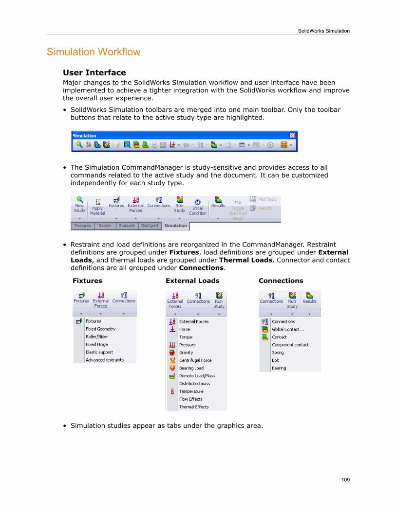
Simulation Workflow
User InterfaceMajor changes to the SolidWorks Simulation workflow and user interface have beenimplemented to achieve a tighter integration with the SolidWorks workflow and improvethe overall user experience.
• SolidWorks Simulation toolbars are merged into one main toolbar. Only the toolbarbuttons that relate to the active study type are highlighted.
• The Simulation CommandManager is study-sensitive and provides access to allcommands related to the active study and the document. It can be customizedindependently for each study type.
• Restraint and load definitions are reorganized in the CommandManager. Restraintdefinitions are grouped under Fixtures, load definitions are grouped under ExternalLoads, and thermal loads are grouped under Thermal Loads. Connector and contactdefinitions are all grouped under Connections.
ConnectionsExternal LoadsFixtures
• Simulation studies appear as tabs under the graphics area.
109
SolidWorks Simulation

• Only the active study appears in the Simulation study tree. In earlier releases, allstudies appeared in the AnalysisManager tree.
• The Loads/Restraints folder has been removed from the Simulation study tree andthe specific load or restraint definitions appear in their External Loads or Fixturesfolders. The Contacts/Gaps folder has been removed from the Simulation study treeand the contact definitions now appear in the Connections folder.
• Load, restraint, and connector objects applied to a body are shown under the bodyicon in the Simulation study tree.
• Each Simulation study tab displays information specific to the study type. For example,a static study lists Fixtures, External Loads, and Mesh, while an optimization studylists Objective, Design Variables, and Constraints. The Parameters, DesignScenario and Results folders appear in the Simulation study tree only if at least oneobject of that type exists in the study; otherwise, these folders are hidden.
• PropertyManagers have been redesigned to show by default the most commonly usedoptions under the Standard group box and the less frequently used options underAdvanced.
• A new Split tab is added to the Fixtures, External Loads, and ConnectorsPropertyManagers. The Split tab allows the creation of split faces within thePropertyManager. You can split a selected face of a solid geometry by creating a sketchand projecting it on the face, or by intersecting other faces with the selected one. Usethe Split tool to apply features to the desired portions of faces.
• When you apply a load, restraint, or connector to a valid geometry, you can previewthe object symbol in the graphics area by hovering over the selected geometry. Youdo not have to click to display the object symbol to appear.
• You can double-click a fixture or load symbol in the graphics area to display thecorresponding PropertyManager.
110
SolidWorks Simulation

• All applicable SolidWorks entities are accepted as selections. For example, cylindricalfaces, axes, and sketch lines are accepted where a linear direction is needed.
• In the Gravity PropertyManager, the default direction is selected as normal to theBottom view orientation plane (negative Y direction). You can add additional gravitycomponents under the Advanced group box.
• The Connectors PropertyManager now has a message window with tips for eachconnector type.
Managing Simulation Studies
Create a study• Click New Study (Simulationtoolbar), or
• Click Simulation, Study, or• Right-click under the graphics area andselect Create New Simulation Study.
Click its tab. The Simulation study treeappears.
Activate a study
Right-click its tab and select Delete.Delete a study
Rename a study • Double-click its tab and type a new name,or
• Right-click its tab and select Rename.
Right-click its tab and select Duplicate.Specify a name and a configuration for theduplicate study.
Duplicate a study
Activate Study A, select the desired featuresin the Study A tree, and drag them to theStudy B tab.
Copy features from Study A to Study B
The mesh type has been removed from the Simulation study definition. See MeshSelection on page 126.
111
SolidWorks Simulation

General
• The magnifying glass feature is supported for Simulation studies. Press G to invokethe magnifying glass. See Using the Magnifying Glass on page 17.
• When the program detects large displacement in static studies, the solver issues amessage that allows you to proceed with the small displacement solution, orautomatically activate the large displacement option and run. If you click Yes, theprogram sets the large displacement option on and restarts the solver automatically.In the Static dialog box, the Large displacement flag is selected.
• (Professional) The Sparse solver is enhanced for 64-bit machines to solve large modelsby optimizing memory allocation for frequency and buckling studies.
• When you run one or multiple Simulation studies, they now run as backgroundprocesses. Right-click the study and select Run. Simulation continues to run in thebackground after the SolidWorks session is ended. When the simulation completes,results are stored in the designated directory.
To run multiple studies, click the down arrow on Run , and select Run AllStudies.
• Simulation API Help now supports connectors.
Simulation Studies
Simulation AdvisorAn improved version of Analysis Advisor, called Simulation Advisor, helps you:
• Determine the proper study types and create them automatically• Define internal interactions between various bodies in the model as well as externalinteractions between the model and the environment
• Assess the safety, including possibilities of failure due to fatigue• Optimize the model• Interpret results
The Simulation Advisor drives the interface by starting the appropriate PropertyManagersand includes links to online help topics for more information. Simulation Advisor workswith the Simulation user interface and opens PropertyManagers when you select specificoptions. For example, Simulation Advisor can help you create the proper studyautomatically.
SensorsSimulation sensors are integrated with SolidWorks. The new sensors definition allowstracking of Simulation results across multiple studies. Simulation sensors now providevisual and sound alerts when tracked values exceed pre-defined threshold limits.
• Sensors for tracking Simulation data are now part of the SolidWorks SensorsPropertyManager defined in the FeatureManager design tree. To add a sensor, right-clickSensors in the FeatureManager design tree and select Add Sensor.
• For documents with multiple studies, sensor entities are updated automatically to showresults of the active study.
112
SolidWorks Simulation

• You can set a sound alarm notification to warn you when data values are equal to,greater than, or less than a threshold limit. In the Sensors PropertyManager, checkAlarm and set the notification criteria.
• Sensors can now track factor of safety data for connectors in addition to stress, strain,displacement, connector forces, free body forces, thermal results, velocity, andacceleration. Trend tracker graphs are also defined as sensor objects. Sensor objectsare listed under the Sensors folder in the FeatureManager design tree.
• You can defineWorkflow Sensitive sensors on vertices or on reference points whereyou want to graph results from transient studies such as nonlinear, linear dynamic,drop test, and transient thermal. Design scenarios also support Workflow Sensitivesensors. In the Sensors PropertyManager, under Data Quantity, select WorkflowSensitive. Under Properties, select vertices or reference points to graph results.
For legacy studies, selection entities that were listed under Locations for Graphs(Result Options PropertyManager) appear as Workflow Sensitive sensors inthe Sensors folder. Legacy Tracked Data Graphs are also mapped to sensors.
See Defining Sensors in the help.
MaterialThe material libraries for SolidWorks and SolidWorks Simulation have been merged intoa single database.
Enhancements to the material user interface:
• Three new tabs, Custom Properties, Application Data and Favorites, have beenadded in the Material dialog box.
1. Use the Custom Properties tab to define new properties for custom-definedmaterials.
2. Use the Application Data tab to include any descriptive information forcustom-defined materials. You can include the content of Application Data inreports. Select Include Application Data under Report Options.
3. Use the Favorites tab to apply most commonly used materials. Right-clickMaterialin the FeatureManager design tree and select from the list of materials that appearin the menu.
• Source text fields have been added in the Properties, Tables & Curves, and FatigueSN Curves tabs to include reference information. Type the source of reference forspecifying material properties. Reports include the content of the Source field.
• The new Default failure criterion option has been added under Properties. Selectan appropriate failure criterion for each material. The user-defined failure criterion isconsidered by default for the Factor of Safety plot when you select Automatic forCriterion in the Factor of Safety PropertyManager.
113
SolidWorks Simulation

(Premium) Composite Shells
In earlier releases, only single-layered shells were supported. In this release, you candefine a composite shell with up to 50 layers. Each layer can have a different isotropicor orthotropic material.
You can use composite materials for linear static, frequency, and buckling studies. Theplies are assumed to be perfectly bonded with no bonding thickness and negligible sheardeformation between them.
SolidWorks Simulation supports these composite options:
• Symmetric laminate: Define a symmetric stack with respect to materials, plyorientations, and thicknesses about the mid-plane. Material properties can be linearelastic orthotropic, or isotropic.
• Unsymmetric laminate: Define an unsymmetric stack with respect to materials(orthotropic or isotropic), ply orientations, or thicknesses about the mid-plane.
• Sandwich composite: These are special laminates with three plies arranged in symmetriclay-up about the mid-plane. Material properties can be linear elastic orthotropic, orisotropic. The outer two plies (skins) should be stiffer than the middle ply. The middleply (core) is usually thicker than the outer plies.
You define ply orientation for composites in the modified Shell DefinitionPropertyManager. You can align plies directly on geometric features without using referencegeometry.
After running a static study, you can plot stress values (at top and bottom faces) for eachply or maximum values across all plies. You can also plot stresses in the ply-angledirections.
To plot stresses along the ply-angle direction:
1. In the Stress Plot PropertyManager, select SX:X Normal Stress.2. Under Composite Options, check Display results in ply direction on compositesurfaces.
114
SolidWorks Simulation

To plot stresses transverse to ply-angle direction, select SY:Y Normal Stress inStep 1.
In addition to all stress quantities available for shells, you can also plot interlaminar shearstress. Interlaminar shear stress is reported in local (material) coordinate system for eachshell.
Failure Criteria for Composite Shells
To determine whether a laminate will fail due to applied loading, the program firstcalculates stresses in all plies. It applies next a failure criterion based on these stresslevels using a failure theory. A laminate is considered to fail when at least one ply fails.
The program applies the Tsai-Wu, Tsai-Hill, and Max stress failure theories to each ply.Tsai-Hill and Tsai-Wu are interactive theories that consider interaction between differentcomponents of stress in the failure criterion. The Max stress theory considers anon-interactive stress-based criterion.
See Composite Shells in the help.
Example of a Composite Shell StudyYou create a buckling study to examine the behavior of a cylindrical composite panel witha circular hole under a compressive load of 100 kN.
To create a composite shell study:
1. Open Simulation\composite-example.sldprt
2. To create a new study, click Study > New Study on the SimulationCommandManager.
3. Under Type, select Buckling , then click .A Simulation study tab appears below the graphics area and a Simulation study treeappears in the SolidWorks FeatureManager design tree.
4. In the Simulation study tree, right-click the shell icon and select Edit Definition
. Under Type, select Composite. Under Composite Options:a) Set Total Plies to 16.b) Select Symmetric and All Plies Same Material.c) Select Rotate 0o Reference to rotate the 0 degree ply-angle reference orientation
by 90 degrees.
d) Select mm in Unit .e) Enter the Thickness and Angle data for the first eight plies:
115
SolidWorks Simulation

AngleThicknessPly
450.1421
-450.1422
900.1423
00.1424
00.1425
900.1426
-450.1427
450.1428
The remaining eight plies are populated automatically, because the lay-up issymmetric. The program locates the plies from the bottom to the top shellface. The ply lay-up is reversed if you flip the shell faces.
f) Under Composite Orientation, select Mirror Orientation.
5. To apply the same material properties for all plies, click .
6. In the Material dialog box, do the following, then click :a) Select Custom defined.b) For Model Type, select Linear Elastic Orthotropic.c) Set Units to SI.d) Type Composite1 for Name.
116
SolidWorks Simulation

e) Type these material properties:
ValueProperty
135e9Elastic modulus in x
13e9Elastic modulus in y
0.38Poisson's ratio in xy
6.4e9Shear modulus in xy
4.3e9Shear modulus in yz
6.4e9Shear modulus in xz
1.5e3Mass density
The program highlights the reference orientation for 0 degree ply angle on thegeometry by means of stripes. The material fiber direction for each ply, which isthe X directionfor material properties is highlighted on the geometry. The Ydirection is transverseto fiber direction (on surface) and the Z direction is normalto the ply surface. The images show the X, Y and Z directions for fiber directionangles 0 degrees and 60 degrees.
Fiber direction angle: 60 degreesFiber direction angle: 0 degrees
7. Drag the Fixtures and External Loads folders from the Ready study tree toStudy 1 tab.The software copies restraints and loads from Ready study to Study 1.
8. Mesh the panel with the Curvature-based mesher.
a) Set maximum element size to 5 mm.b) Check Draft Quality Mesh under Advanced.c) Run the study.
9. Right-click Results and select Define Mode Shape/Displacement Plot . Plotthe first two buckling mode shapes.
117
SolidWorks Simulation

Second Buckling ModeFirst Buckling Mode
10. Right-click Results and select List Buckling Load Factors .The first five buckling loads agree with numerical results.
Mode 5Mode 4Mode 3Mode 2Mode 1BucklingLoads (kN)
151.3140.1116.2109.6107Reference
166.7140.1114.5110.7107.6SolidWorksSimulationProfessional
Multiply buckling load factors by 100 to get the actual buckling loads.
Reference:
1. Stanley G.M., "Continuum Based Shell Elements," Ph.D. Dissertation, Departmentof Mechanical Engineering, Stanford University, 1985.
Beams
The algorithm used to evaluate joints connecting structural members is improved. Inearlier releases, some joints for models with crossed beams or complex geometries wereincorrectly defined. In this release, the software automatically identifies joints for:
• Touching or interfering structural members.• Non-touching structural members within a certain distance (tolerance). The softwarecomputes an optimal tolerance value, but the user can overwrite it. In the Edit JointsPropertyManager, under Criteria, check the option Treat as joint for clearance lessthan and set the threshold distance between structural members.
The Pinball Options in the Edit Joints PropertyManager is removed. The newoption Treat as joint for clearance less than replaces the definition of pinballradius.
(Premium) Nonlinear static studies now support linear elastic beam elements. All types ofloading and restraints for beams that can be defined in static studies are supported fornonlinear studies. You can create shear and moment diagrams and list beam forces andstresses. Large displacement formulation is supported.
118
SolidWorks Simulation

No penetration contact is not supported when beam elements are part of the mesh,unless they are treated as solids. To treat a beam as a solid, right-click the beamicon in the study tree and select Treat as Solid.
(Professional) Thermal Studies
• You can now select all of the exposed faces of a part or assembly to apply thermalloads. This option is available in the Temperature, Convection, Radiation, HeatFlux, and Heat Power PropertyManagers. Click Select all exposed faces in a thermalload PropertyManager. In assembly documents, you can apply thermal loads to facesof all components. Fully contacting faces of parts are not selected for thermal loads.However, exposed portions of partially contacting faces are selected.
Model with partially touching faces (total of12 exposed faces)
Model with fully touching faces (total of10 exposed faces)
• Interaction of thermal studies with static, nonlinear, or transient thermal studies nowaccommodates dissimilar meshes. After obtaining the temperature distribution from athermal analysis with certain mesh properties, you can import the temperature datato a static, nonlinear, or transient thermal study with different mesh properties.
Finer mesh for static studyCoarse mesh for thermal study
(Professional) Geometry from Deformed ShapeAfter running a static or nonlinear study, you can now save the deformed geometry as anew part document, or as a new configuration and create new studies based on it. Studieswith solids and surfaces are supported.
You can use this functionality to control the shape of the deformed model for manufacturingpurposes. For example, consider a planar plate subjected to a uniform pressure p. If yousave and manufacture the deformed shape of the plate under a uniform pressure -p, theplate will remain planar when the pressure p is applied.
119
SolidWorks Simulation

The creation of new studies from deformed geometries of models with beams orsheet metals is not supported in this release. Deformed shapes of assemblydocuments are saved as multibody parts.
To save the deformed geometry of a part or assembly to a new document:
1. Open Simulation\Tutor1.sdprt
2. Run the Ready study.
3. Right-click Results and select Create Body from Deformed Shape.4. In the PropertyManager:
a) Under Save Body as , click Save As New Part/Assembly.b) Type Deformed in Part name.
c) Click .A new document Deformed.sldprt is created in the <Examples_dir> directory.
If you run a nonlinear study, the software saves the deformed geometrycorresponding to the last solution step.
Stress/Deformation
A Stress/Deformation tool is included on the Sheet Metal, Evaluate, and Weldmentstoolbars to guide you through the common tasks needed to perform an analysis and viewthe results.
The Stress/Deformation tool works with SolidWorks Simulation Quick Tips to assistyou through the analysis workflow. Selecting Stress/Deformation from the Sheet Metalor Weldments toolbars creates a new Static study with gravity applied in the negative Ydirection and displays SolidWorks Simulation Quick Tips.
(Premium) Remote Load/Mass for Linear Dynamic StudiesYou can apply remote loads, or treat a solid body as a remote mass for linear dynamicstudies.
You can apply remote loads that are time-dependent for time history studies, orfrequency-dependent for harmonic and random vibration studies. To apply a remote load,
click External Loads , Remote Load/Mass .
In assembly or multi-body part documents, you now have the option to treat one or moresolid bodies as remote masses for linear dynamic studies. Bodies treated as remotemasses are excluded from meshing, but their mass properties and moments of inertiaare considered in frequency and dynamic analyses. The application of remote mass reducesthe mesh size and expedites the solution process, particularly for large assemblies thatare subjected to dynamic loading environments.
To treat a solid body as a remote mass, right-click it in the Simulation study tree andselect Treat as a Remote Mass. The body appears in the Remote Mass folder. Youcan select only one body at a time for remote mass.
You can also define a remote mass in with the Remote Load/Mass PropertyManager.
120
SolidWorks Simulation

Bodies treated as remote masses are notmeshed.
All bodies are meshed.
See Treat as Remote Mass in the help.
Assemblies
Enhancements to Assembly Modeling
When working with assemblies, you can exclude selected solid bodies from simulation ortreat them as rigid, flexible, floating, or fixed in space. Right-click the part in the studytree to set these options:
• Exclude from Analysis. The part is excluded from the study without suppression.This option toggles to Include in Analysis.
• Make Rigid. The body is not allowed to deform. Results for its strains and stressesare not computed. However, its contact interactions are considered in simulation. Thisoption toggles to Make Deformable. (Available for static and frequency studies).
• Make Deformable. The body is allowed to deform to the extent allowed by its restraintsand connections to other parts. Results for its strains and stresses are available.
• Fix. The body is not allowed to move. Since the entire body cannot move, it is effectivelymade rigid as well. A fixed body can still transfer contact interactions to touching parts.This option toggles to Float. (Available for static and frequency studies).
To fix a portion of a body, use the Fixed restraint.
• Float. The body can move to the extent allowed by its restraints and connections toother parts. A floating body may be either rigid or flexible depending on the MakeRigid/Make Deformable setting.
You should treat a component as rigid only if it is much stiffer than its surroundingcomponents of interest.
For example, the figure below shows stress results for a symmetrical, no penetrationcontact between a rigid sphere and a flexible block. Note that no stresses develop in thesphere.
121
SolidWorks Simulation

Sheet Metal Parts
You can now analyze assemblies made of sheet metal parts, solids, and surfaces. Sheetmetal bodies mesh with shell elements. The mesh is located at the mid-surface of thesheet metal.
You can apply all Simulation features directly to the solid geometry. The solver transfersloads, restraints, contact definitions, and connectors to the mid-surface.
Mesh with Shells at the Mid-surfacesAssembly with Two Sheet Metal Parts
Study Tree Enhancements
When you add, delete, or suppress components or bodies in an assembly document inthe SolidWorks FeatureManager design tree, the existing Simulation studies are updatedautomatically. Warning icons next to the Mesh and Results folders in the Simulationstudy tree alert you to changes in model geometry.
Connectors
Factor of Safety for ConnectorsThe Factor of Safety Check is extended to bolt and pin connectors.
After running a static or nonlinear study, you can identify safe and failed connectors. Toperform a Factor of Safety (FOS) check for bolt and pin connectors, in the Connectors
122
SolidWorks Simulation

PropertyManager, expand Strength Data and enter the tensile stress area, connectorstrength, and minimum safety factor. When the analysis is complete, you can view go/nogo status for all connectors, as well as their factors of safety. In the graphics area,connectors that are safe are show in green and connectors that have failed are show inred.
For nonlinear studies, the program performs FOS check for each solution step.
See Factor of Safety for Connectors in the help.
To perform a FOS check for bolt connectors:
1. Open Simulation\Basketball_Hoop.sldasm.
2. Right-click the Ready study tab and select Duplicate.3. In the dialog box, type FOS_check for Study Name. Click OK.
A new FOS_check study tab appears at the lower portion of the graphics area.
4. Right-click Bolt Connector-1 in the FOS_check study tree and select Edit
Definition .5. In the PropertyManager, check Strength Data and set the following:
• Select Known Tensile Stress Area.• Type 40 (mm2) for Tensile Stress Area.• Set Unit to psi for Bolt Strength, and type 3.e07.
6. Click .7. Repeat steps 4, 5, and 6 for the other three bolt connectors.8. Run the study. In the message window, click No to solve without using the large
displacement option.
9. Right-click Results and select Define Pin/Bolt Check Plot.
10. Click .All four connectors are safe and are listed under the OK folder . The boltconnectors are colored green in the graphics area.
Connectors that fail the FOS check are listed in the Needs attention folder.Failed connectors are colored red in the graphics area.
11. Expand the OK folder and click Bolt Connector-2.A callout in the graphics area lists the factor of safety for the connector.
123
SolidWorks Simulation

Bolt ConnectorsBolt connectors have been enhanced.
• Bolt connectors for shells are now available. You can define bolts through a mixed stackof solids, shells, and sheet metal bodies.
• (Premium) Multi-layered bolts are now available for nonlinear studies. To bolt more thantwo solid components, in the Connectors PropertyManager, select Bolt series underAdvanced Option, then select the cylindrical faces from the middle components. Fornonlinear studies, you can define multi-layered bolts through solid bodies only.
• (Premium) Bolts for 1/2 or 1/4 symmetry are now available for nonlinear studies. Todefine a symmetric bolt, in the Connectors PropertyManager, select Symmetricalbolt under Advanced Option.
124
SolidWorks Simulation
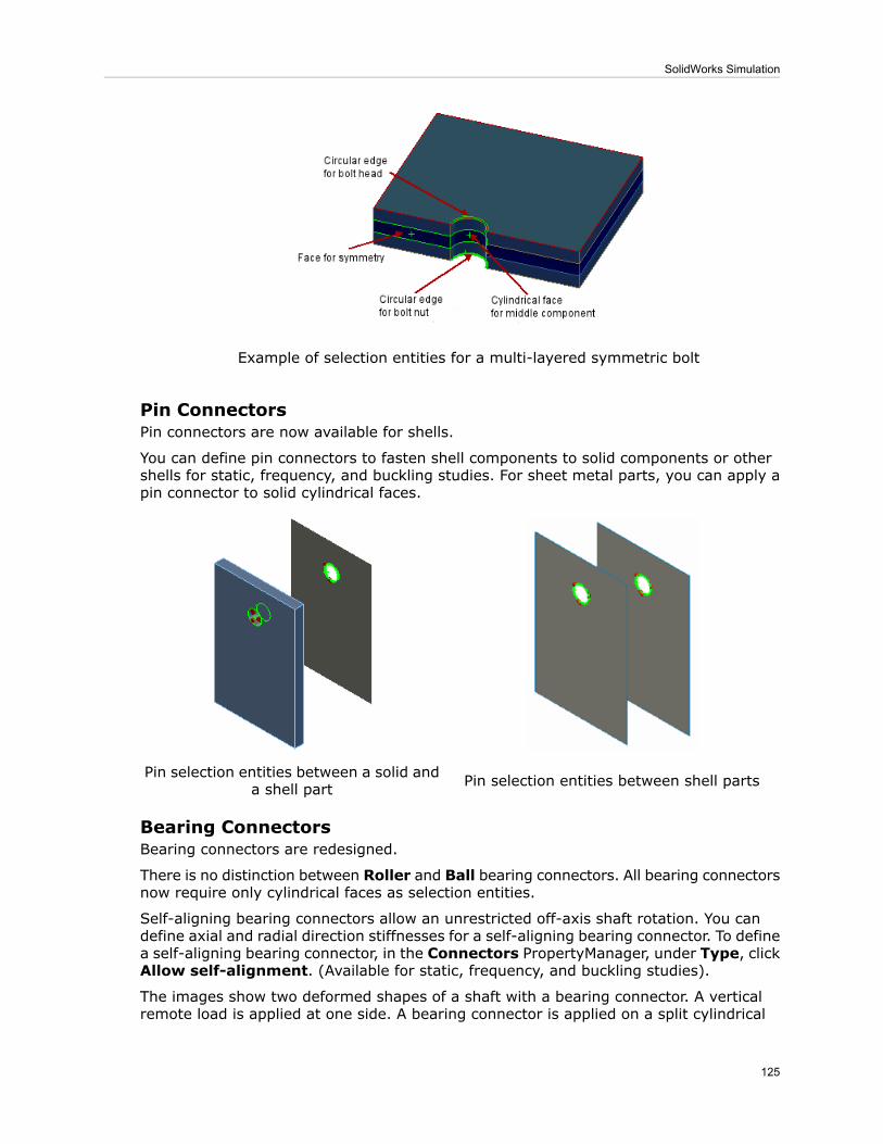
Example of selection entities for a multi-layered symmetric bolt
Pin ConnectorsPin connectors are now available for shells.
You can define pin connectors to fasten shell components to solid components or othershells for static, frequency, and buckling studies. For sheet metal parts, you can apply apin connector to solid cylindrical faces.
Pin selection entities between shell partsPin selection entities between a solid anda shell part
Bearing ConnectorsBearing connectors are redesigned.
There is no distinction between Roller and Ball bearing connectors. All bearing connectorsnow require only cylindrical faces as selection entities.
Self-aligning bearing connectors allow an unrestricted off-axis shaft rotation. You candefine axial and radial direction stiffnesses for a self-aligning bearing connector. To definea self-aligning bearing connector, in the Connectors PropertyManager, under Type, clickAllow self-alignment. (Available for static, frequency, and buckling studies).
The images show two deformed shapes of a shaft with a bearing connector. A verticalremote load is applied at one side. A bearing connector is applied on a split cylindrical
125
SolidWorks Simulation

face of the shaft. When the Allow self-alignment option is selected, the cylindrical faceof the bearing connector rotates off its axis. When the option is cleared, the cylindricalface is restricted from off-axis rotation.
Shaft with a bearing connector.
Allow self-alignment is cleared.Allow self-alignment is selected.
To prevent rotational instability that can cause numerical singularities, check Stabilizeshaft rotation in the Connectors PropertyManager.
Mesh
Mesh SelectionYou no longer need to select a mesh type when creating a new study. The softwareautomatically assigns the appropriate mesh type to bodies based on their geometryfeatures:
• Solid bodies mesh with solid elements. You can still mesh a solid body as a shell bydefining reference surfaces first.
• Surface bodies mesh with shell elements. The software assigns a default shell thicknessand thin shell formulation to each surface body. You can edit the default shell definitionbefore running the study.
• Sheet metal bodies with uniform thicknesses mesh with shells created at mid-surfaces.The software assigns a single shell to each sheet metal body. Sheet metal bodies withnon-uniform thicknesses mesh with solid elements.
For drop test studies only, sheet metals parts mesh with solids.
• Structural members mesh with beam elements and the program automatically detectsthe beam joint group.
The icons in the study tree indicate the mesh type:
126
SolidWorks Simulation

Mesh ElementBodyIcon
Tetrahedral solid elementsSolid
Triangular shell elementsSurface and sheet metal
Beam and truss elementsStructural member and weldment
After you create a study, you can change the default mesh types for selected bodies:
• To treat a solid body as a beam , right-click it in the study tree and select Treat
as Beam. Its icon changes to . To convert it back to a solid, right-click and selectTreat as Solid.
• To treat a sheet metal body as a solid , right-click it in the study tree and select
Treat as Solid. Its icon changes to . To convert it back to a sheet metal body,right-click and select Treat as Sheet Metal.
To mesh a thin solid body with shells, create a mid-surface.
Curvature-based MesherThe curvature-based mesher now allows meshing of surfaces in addition to solid bodies.
The curvature-based mesher generates a finer mesh on areas of high curvature andtransitions the mesh automatically. It supports studies with solid, shell, and beam elementsthat use incompatible mesh for contact conditions.
To mesh with the curvature-based mesher, in the Mesh PropertyManager under MeshParameters, select Curvature based mesh.
Example of a 3D surface model with varying curvature meshed with the curvature-basedmesher. The mesher generates finer mesh at regions where the change in curvature isprominent.
Top viewIsometric view
For shell components with touching edges, mesh is always compatible when youselect the curvature-based mesher.
127
SolidWorks Simulation

Mesh ControlThe user interface for component mesh control has been enhanced.
The software automatically refines the mesh based on the volume of the individualcomponents. Previously, if you wanted to specify different element sizes for differentcomponents in an assembly, you assigned Component significance values in theMeshControl PropertyManager.
To apply mesh control to multiple bodies simultaneously, select Use per part size in theMesh Control PropertyManager. The program assigns an element size for mesh controlto each component based on each component's volume. You can still control the elementsize for mesh control by moving the slider under Mesh Density.
You can now apply mesh control on components and edges in addition to faces whenyou choose the curvature-based mesher.
Simplify Model for MeshingA Simplify Model for Meshing option provides quick access to the SolidWorks Utilities
Simplify tool.
To select the Simplify Model for Meshing option, right-click Mesh in the Simulationstudy tree. You can also click Utilities > Simplify.
Simplification of geometry can alter stress results significantly.
Contact and Bonding
Contact for Nonlinear StudiesThe solution time for nonlinear problems involving studies of large assemblies with Nopenetration contact has been improved.
A new Surface to surface contact option is available in the Contact Set PropertyManager.The application of a finer mesh in the contact area improves the results. You can still usethe other contact options, Node to node and Node to surface, under Advanced optionsin the Contact Set PropertyManager.
The same approach is used for draft-quality mesh, but using high-quality meshmakes the increased speed for simulation more evident.
No Penetration and Shrink Fit ContactThe interface is simplified by removing options for contact type.
The contact set interface is simplified for the No penetration and Shrink fit options inthe Contact Set PropertyManager (static study). The program assigns by default a Nodeto surface contact type to all contact set definitions without user input.
You can assign a Surface to surface contact type to all contact definitions by checkingImprove accuracy for contacting surfaces with incompatible mesh (slower) inthe Static dialog box.
For legacy studies, you can still access the Node to node, Node to surface, andSurface to Surface contact types. On the Default Options > Mesh, check Show
128
SolidWorks Simulation

advanced options for contact set definitions (No penetration and shrink fitonly). The No Penetration contact type options become available under Advancedin the Contact Set PropertyManager.
The source and target grouping for entities is eliminated. You identify faces, edges, orvertices into Set 1, and faces into Set 2 in the Contact Set PropertyManager. The solveridentifies source and target entities automatically.
Shell Thickness Consideration
You can now consider the thicknesses of surface and sheet metal components that meshwith shells for no penetration and virtual wall contact. In earlier releases, shell thicknesseswere not considered for contact and bonding. In this release, contact is realized whenthe distance between the midsurfaces of two shells becomes (t1+t2)/2 as shown in thefigure. Contact forces are then applied regardless of any clearance shown in result plots.Shell thickness consideration is available for static and nonlinear studies.
• The thicknesses of surface and sheet metal components that mesh with shells for nopenetration and virtual wall contact is always considered when you create new staticand nonlinear studies. To improve the results of legacy studies, rerun the studies.
• No initial interference should exist between the shell bodies.• For models that have both solid and surface/sheet metal components, the global optionIgnore clearance for surface contact in the Static dialog box is not supported forno penetration and virtual wall contact. However, you can still set a local condition forignoring clearances between solid components in the Contact Set PropertyManager.
Bonding
Enhanced algorithms automatically bond touching entities for the following cases:
• A face or edge of a shell with a solid• A face or edge of a shell with another shell• A face of a shell with a structural member
Make sure that the global contact condition is set to Bonded.
For touching faces of sheet metal components that mesh with shells created atmid-surfaces, the program transfers the bonding contact to mid-surface shellsautomatically.
129
SolidWorks Simulation

Side view of mesh (zoomed)Surface edge touching a sheet metal face
Side view of mesh (zoomed)Solid face touching a sheet metal face
Bonding between touching structural members with a sheet metal face is also automaticallycreated and transferred to mid-surface shells.
Side view of mesh (zoomed)Structural members touching a sheet metalface
For a Bonded Contact Set between shell components that is defined with an edge (Set1) to edge (Set 2) selection set, meshing for the coincident shell edges is compatiblewhen you use the Curvature-base mesher.
Result Viewing
Factor of Safety CheckFactor of Safety plots have been expanded to studies with shell and mixed mesh.
130
SolidWorks Simulation
Factor of Safety plots can now assess the safety of design for shell (single-layered andcomposite), beam, and mixed mesh models based on a failure criterion assigned for eachmaterial. The Factor of Safety PropertyManager has been enhanced with new options:
• An Automatic option allows you to select the most appropriate failure criteria acrossall element types. When you select Automatic in Criterion, the software applies thefollowing conditions:
1. The Default failure criterion assigned in theMaterial dialog box for each material.
See Default failure criterion on page 113.
2. If you have not assigned a default failure criterion in the Material dialog box, thesoftware assigns the Mohr-Coulomb stress criterion.
3. If you selected Max von Mises or Max shear (Tresca) criterion for a beam material,the software uses the yield strength as the allowable stress.
4. If you selected Max normal or Mohr-Coulomb criterion for a beam material, thesoftware uses the tensile strength as the allowable stress.
• A new radio button Show combined stress on Beams is added in the Factor ofSafety PropertyManager to calculate the factor of safety for beams with the worst casecombined stress.
• New options for shells allow you to perform design check with the minimum, maximum,top face, or bottom face stresses. The Membrane and Bending options are removed.
• The Tsai-Wu, Tsai-Hill, and Max stress failure criteria allow you to perform factor ofsafety check for composite shells.
In general, for multi-directional laminates, you can test all three criteria todetermine the worst case for increasing safety of design.
Results
• The deformation plot is merged with the Plot Results menu and the Default Optionsdialog box for plots. You can still access deformation plots through the DisplacementPlot PropertyManager. Clear Show colors under Deformed Shape.
Legacy deformation plots are shown as displacement plots with the Show colorsoption cleared.
• A new button Deformed Result (Simulation toolbar) toggles the deformed andundeformed shape of the model in an active plot.
• (Premium) Strain energy density plots are now supported for harmonic and randomvibration dynamic studies. To create a strain energy density plot, right-click the Resultsfolder and select Define Strain Energy Density Plot.
• Selection of nodes and vertices locations for time history and response graphs are nowpart of the sensor definition. DefineWorkflow Sensitive sensors for locations whereyou want to graph results from nonlinear, dynamic, and drop test studies and designscenarios.
• You can superimpose a Design Insight plot on your model while you are editinggeometry features.
131
SolidWorks Simulation

Compare Results
A Compare Results tool is available for all study types and lets you easily comparestudies.
Compare Results is available whenever multiple studies or results are available. Youcan create:
• Comparisons of the current plot to the same study plot from up to three other studies• Comparisons of arbitrary plots from different studies• A quick view of the available plots for the current study at the same time
132
SolidWorks Simulation

11Other Functionality
This chapter includes the following topics:
• Installation• Application Programming Interface• DWGeditor• PhotoView 360• SolidWorks eDrawings• SolidWorks Rx
Installation
Administrative Image Configuration and DeploymentSolidWorks Administrative Image configuration and deployment capabilities have beenenhanced.
Option Editor EnhancementsThe SolidWorks Administrative Image Option Editor now supports most SolidWorksinstallation parameters.
• Specify company contact and product usage information• Start installations automatically• Create a diagnostic log for each installation• Use a different user account when installing• Update an existing installation location or create a new location• Specify the locations of standard libraries shared by users and groups• Use pre-defined options from a previous release or a Copy Settings wizard export file
You now can customize administrative image settings for each machine, rather than foreach user. A single administrative image now can serve all users.
Upgrading an Existing Administrative ImageUpgrading an existing administrative image has been simplified, both in the InstallationManager and in the documented instructions.
Restoring Settings from a Previous ImageWhen creating or updating an administrative image, you now can re-use installationsettings from an existing image.
You can re-use users.xml settings from only SW 2009 images. You cannot re-usesettings from images created using versions prior to SW 2009.
133

Installation Manager Support for Manually Downloading FilesIt is now possible to use the Installation Manager even when files must be downloadedmanually.
The Installation Manager is capable of downloading all files needed to complete aninstallation. However, in some cases proxy servers installed on the local network or byan internet service provider might prevent an application (such as Installation Manager)from downloading files, while permitting users to download files manually using an internetbrowser.
Installation Manager enhancements to support manually downloaded files include:
• One set of files: The Installation Manager and the Customer Portal now use the sameset of downloaded files for installation. You can download manually all files theInstallation Manager requires to complete an installation.
• Automatic processing of manual downloads: The Installation Manager now detectsand processes all files downloaded manually, even if you downloaded files to a differentfolder or if you missed any files. You can browse to any folder to locate previouslydownloaded files and then download any remaining files (manually or automatically).
• Downloadingmanually within the Installation Manager: The Installation Managernow specifies exactly what files are required based on what products you are installingand the system requirements. Select the Individual Files option on the Ready toDownload page and follow the instructions. A Web page listing all required files appearsin the default Web browser. Click the links to download the files and then follow theinstructions to place each file on the computer.
Installation Error Message LinksUnder some error conditions, the SolidWorks Installation Manager provides links toWeb-based installation information.
This new Web-based capability provides immediate access to the latest installationinformation, supplementing the information provided in the installation documentation.
Application Programming InterfaceClick Help > API Help to access the SolidWorks Application Programming Interface (API)Help systems.
The major enhancements made to the SolidWorks API in SolidWorks 2009 are:
• VSTA (Microsoft Visual Basic .NET and C#) macro recording added. Microsoft VisualStudio 2005-formatted, Microsoft .NET version of API Help introduced to support thesenew macro recording languages.
• Access to coordinate features added (ICoordinateSystemFeatureData interface andIFeatureManager::InsertCoordinateSystem method).
• Access to Save Bodies features added (ISaveBodyFeatureData interface andIFeatureManager::CreateSaveBodyFeature method).
• Support for creating and attaching callouts to a location in space, hiding and showingcallouts, and getting and setting the callout's leader properties added(IModelDocExtension::CreateCallout, ICallout::Display, ICallout::GetLeader, andICallout::SetLeader methods).
• Support for getting sketch's regions and contours added(ISketch::GetSketchRegionCount, ISketch::GetSketchRegions,ISketch::IGetSketchRegions, ISketch::GetSketchContourCount,
134
Other Functionality

ISketch::GetSketchContours, ISketch::IGetSketchContours, ISketchContour::IsClosed,and ISketchRegion::GetFirstLoop methods).
• Support for reordering and reorganizing components added(IAssemblyDoc::ReorganizeComponents and IAssemblyDoc::IReorganizeComponentsmethods, and DAssemblyDocEvents ComponentReorganizeNotifyEventHandler delegate).
• Support for getting and setting display dimensions' extension line gaps and jogs added(IDisplayDimension::GetJogParameters, IDisplayDimension::GetWitnessLineGap,IDisplayDimension::SetJogParameters, and IDisplayDimension::SetWitnessLineGapmethods).
• Support for selecting hidden bodies added (IBody2::DisableDisplay property).
• Support for editing selected reference points added(IFeatureManager::EditReferencePoint method).
• Notifications added to track changes specific to configurations(DAssemblyDocEvents_ConfigurationChangeNotifyEventHandler andDPartDocEvents_ConfigurationChangeNotifyEventHandler delegates).
• Notification added to fire when SolidWorks creates a new file(DSldWorksEvents_FileNewPreNotifyEventHandler delegate and swAppFileNewPreNotifyenumerator). Support to name the newly created file added(ISldWorks::SetNewFilename method).
• Additional support for Motion Studies added (ISimulation3DContactFeatureData andISimulationDamperFeatureData interfaces).
• Support for strongly named macro features added.
See the SolidWorks API Release Notes topic, which is available in the API Help, for a listof all of the changes made to the SolidWorks API 2009.
DWGeditorIn the DWGeditor®, you can use the SolidWorks 2D View Palette to create drawings fromSolidWorks parts and assemblies. After you import a SolidWorks model, you can workwith configurations, display modes, and layers. A drawing entity can be parametricallylinked to the original SolidWorks model, allowing you to update the drawing when themodel changes.
In DWGeditor:
135
Other Functionality

StepsAction
Click Tools > View Palette.Prepare to work with aSolidWorks model
Do one:Open a SolidWorks model
• Click Browse for SolidWorks model and select amodel file.
• Drag a model file from Microsoft Windows® Explorer toDWGeditor.
• Open a model in SolidWorks, then start DWGeditor.
Available views of the model appear on the View Palette.
Clear Insert as Block Reference, then drag the view tothe drawing sheet.
A SolidWorks drawing view entity is added to the sheet.You cannot edit this entity.
Add a view to a drawing witha parametric link toSolidWorks
Select Insert as Block Reference, then drag the viewto the drawing sheet.
A block is added. You can explode the block to createindividual sketch entities.
Add a view to a drawingwithout a parametric link toSolidWorks
Select the object on the drawing sheet and explode it byclicking Modify > Explode.
The parametric link to SolidWorks is removed.
Convert a SolidWorks entityto a block
Click Tools > Update Views.
The SolidWorks drawing view entities are updated.
Update a drawing when amodel changes
Before adding a view to a drawing, on the View Palette:
StepsAction
For a SolidWorks model with more than one configuration,select a new value from Configuration.
Work with a differentconfiguration of the model
Type a value for Drawing View Scale or select SpecifyOn-screen.
Set the size of an object inthe drawing
From Display Style, select Hidden Lines Removed,Hidden Lines Visible, or Wireframe.
Select the display mode foran object
Define layers. Then select distinct layers for Visible LinesLayer, Hidden Lines Layer, and Tangent Lines Layer.
Define visual properties forvisible edges, hidden edges,and tangent edges
PhotoView 360PhotoView 360 is a state-of-the art progressive rendering solution for SolidWorks models.This new product is included for users of SolidWorks Office, SolidWorks Professional, andSolidWorks Premium.
136
Other Functionality

You must have a valid SolidWorks license installed on your system to use PhotoView 360.If you have a valid license but get a license error message, reactivate PhotoView 360 byselecting Activate Licenses from the Help menu.
SolidWorks eDrawings
Graphics Hardware Acceleration OptionsYou can select graphics card hardware acceleration options from the General tab of theOptions dialog box. SolidWorks eDrawings® initially sets these options based on yourgraphics hardware.
Select Graphics boost to use your graphics card hardware acceleration. Select optionsto optimize for speed or appearance.
If you experience display problems with eDrawings and your graphics card is not onthe list of approved graphics cards, close all open files and clear Graphics boost.
Clearing Graphics boost is equivalent to selecting Use software OpenGL inprevious releases.
Appearances and SceneseDrawings now supports the appearances, scenes, and lighting defined in SolidWorks2009 parts and assemblies. eDrawings also now applies floor reflection to parts andassemblies from all supported applications.
You must select Best appearance under Graphics boost to view these displaysettings in eDrawings.
Assembly Bills of Materials in eDrawingseDrawings supports viewing BOM data stored within SolidWorks part or assembly files.You can also save the BOM data to an eDrawings part or assembly file.
When saving the selected SolidWorks document, click Options in the Save As dialogbox, and select Save Bill of Materials features to eDrawings file.
When you open files that include BOMs, you can view a BOM but not move or resizeit.
SolidWorks Rx
Problem CaptureYou can now provide more information when you report a problem.
To start Problem Capture, start SolidWorks Rx and click the Problem Capture tab.
In step a, the Problem Capture Detail form prompts you for more detailed informationthan it did previously.
In step b, when you recreate the problem, you can:
• Use the data from your last SolidWorks session.
137
Other Functionality

• Record a video that recreates the problem in a new SolidWorks session or in the currentsession.
138
Other Functionality

12SolidWorks Professional
This chapter includes the following topics:
• FeatureWorks• PhotoWorks• Design Checker• SolidWorks Tools• SolidWorks Utilities• Toolbox
FeatureWorks
General
FeatureWorks Options Dialog Box Enhancements
• The Options dialog box is reorganized. All existing options are still available. Selectfrom these categories:
• General• Dimensions/Relations• Resize Tool• Advance Controls
• The Resize Tool Recognition Order dialog box lets you set the recognition order forfeatures you create using the resize tool. Upon feature recognition, FeatureWorkscreates resized features in the order you set.
• Click Default to reset all values to the default FeatureWorks values, including thefeature selection filters.
User Interface Enhancements• The PropertyManager has been redesigned to improve usability:
• The single FeatureWorks PropertyManager has been split into three wizard-likePropertyManagers: Feature selection, Intermediate for feature recognitionoperations, and Pattern Recognition.
• Click graphical navigation tools , , , and to move through the wizard-likerecognition process.
• The navigation tools replace the FeatureWorks FeatureManager dialog box, whichhas been removed. The dialog box functionality, such as Recognize Patterns, MapFeatures, and Continue, has been integrated into the PropertyManagers.
• Colored Message boxes in the PropertyManagers guide you through the recognitionprocess.
139
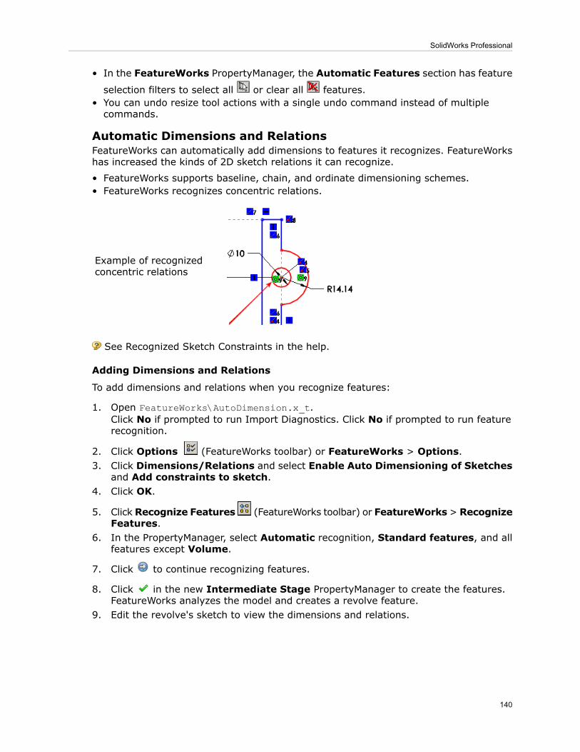
• In the FeatureWorks PropertyManager, the Automatic Features section has feature
selection filters to select all or clear all features.• You can undo resize tool actions with a single undo command instead of multiplecommands.
Automatic Dimensions and RelationsFeatureWorks can automatically add dimensions to features it recognizes. FeatureWorkshas increased the kinds of 2D sketch relations it can recognize.
• FeatureWorks supports baseline, chain, and ordinate dimensioning schemes.• FeatureWorks recognizes concentric relations.
Example of recognizedconcentric relations
See Recognized Sketch Constraints in the help.
Adding Dimensions and Relations
To add dimensions and relations when you recognize features:
1. Open FeatureWorks\AutoDimension.x_t.Click No if prompted to run Import Diagnostics. Click No if prompted to run featurerecognition.
2. Click Options (FeatureWorks toolbar) or FeatureWorks > Options.3. Click Dimensions/Relations and select Enable Auto Dimensioning of Sketches
and Add constraints to sketch.4. Click OK.
5. Click Recognize Features (FeatureWorks toolbar) or FeatureWorks> RecognizeFeatures.
6. In the PropertyManager, select Automatic recognition, Standard features, and allfeatures except Volume.
7. Click to continue recognizing features.
8. Click in the new Intermediate Stage PropertyManager to create the features.FeatureWorks analyzes the model and creates a revolve feature.
9. Edit the revolve's sketch to view the dimensions and relations.
140
SolidWorks Professional

Base Loft RecognitionFeatureWorks can interactively recognize base lofts.
FeatureWorks recognizes base lofts with two or more similar or dissimilar profiles. Theprofiles can be parallel or non-parallel.
Unsupported Loft Entities:
• End conditions Normal to profile and Direction vector• Guide curves• Profile connectors• Splines as profiles
Recognizing Lofts
To interactively recognize base lofts:
1. Open FeatureWorks\BaseLoft.x_t.Click No if prompted to run Import Diagnostics.
2. Do one:
• Click Yes if prompted to run feature recognition.
• Click Recognize Features (FeatureWorks toolbar) or FeatureWorks >Recognize Features.
3. In the PropertyManager:a) Select Interactive under Recognition Mode.b) Select Standard features under Feature Type.
4. Under Interactive Features:a) Select Base-Loft in Feature type.
b) Select the faces shown for End Face 1 and End Face 2 .
141
SolidWorks Professional

5. Click Recognize.
6. Click .
End Conditions for Holes and Cut ExtrudesFeatureWorks has increased the kinds of end conditions it recognizes for holes and cutextrudes.
In addition to Blind, FeatureWorks now recognizes these end conditions for holes andcut extrudes:
• Up to Next• Through All
Use Automatic or Interactive mode to recognize these end conditions.
For holes, FeatureWorks also recognizes these end conditions when you use theresize tool.
Mirror PatternsFeatureWorks recognizes mirror patterns.
You can recognize mirror patterns using Automatic or Interactive mode. FeatureWorksautomatically selects the mirror plane.
Recognizing Mirror Patterns
To automatically recognize mirror patterns:
1. Open FeatureWorks\MirrorPattern.x_t.Click No if prompted to run Import Diagnostics.
2. Do one of the following:
• Click Yes if prompted to run feature recognition.
• Click Recognize Features (FeatureWorks toolbar) or FeatureWorks >Recognize Features.
3. In the PropertyManager, select Automatic recognition and click to recognizefeatures using the other default settings.
4. Under Recognized features, click Find patterns.5. In the Pattern Recognition PropertyManager:
a) Select Automatic in Pattern Recognition Mode.
142
SolidWorks Professional

b) Select Mirror in Pattern Type.c) In Pattern Features, select Boss-Revolve6 shown for Seed feature.
d) Select Boss-Revolve1 shown for Mirror feature.
e) Click .A dialog box reports 2 mirrors found. FeatureWorks calculates mirrors for the revolvesand holes as separate features.
6. Click OK to close the dialog box.
7. Click .FeatureWorks calculates the mirror plane and creates mirrors for all features withvalid mirrors about that plane.
8. In the FeatureManager design tree, select the mirror features to highlight them inthe graphics area.
Resize ToolFeatureWorks® software has increased the number of features you can directly edit usingthe resize tool.
You can directly edit these features using the resize tool:
• Boss revolve• Cut revolve• Edge flange• Hem flange
143
SolidWorks Professional

PhotoWorks
Preview WindowDisplay the Preview window to see an accurate, interruptible, view of a rendered model.Complicated models can take a long time to render. Use the Preview window to savetime before you commit to a full rendering.
Click PhotoWorks > PreviewWindow. When the teapot in the upper right corner stopsspinning, the window has finished updating. Within the Preview window, you can zoom,pan, or change the view orientation.
Small preview windows are updated more quickly than larger ones.
As you change the model in the graphics area, the Preview window synchronizes with,but does not disrupt, your work. The rendering preview restarts for most changes. Whenyou edit features or components, the Preview window pauses until you complete thechange.
Work with the toolbar buttons:
ActionButton
Suspends the preview in its current state. When youresume, the preview undergoes a single translation beforerefinement restarts.
Stop / Resume
Takes a snapshot of the preview as of the moment youclick Save in the Save As dialog box.Save
Displays the entire model within the Preview window.Fit to screen
Selects a smaller area of the model to view within thePreview window.Zoom to area
Views the preview in more or less detail.Zoom In/Out
Changes the position of the preview within the window.Pan
Selects a new orientation, which can be different from theone in the graphics area.View orientation
Abstract ScenesAdditional abstract scenes, including a new default background, are available. On theAppearances/PhotoWorks tab, select Scenes > Basic Scenes.
144
SolidWorks Professional

In a reflective environment, colors and images in real-world scenes can distract from themodel. An abstract scene is an environment more typical of the setup in a photographystudio. It does not contain recognizable objects other than lighting. With abstract scenes,the viewer focuses on the model, rather than the background.
The background and reflective environment are the same in these abstract scenes.
145
SolidWorks Professional

EffectScene
Backdrop - AmbientWhite
Backdrop - Black withFill Lights
Backdrop - Grey withOverhead Light
Backdrop - StudioRoom (default scene)
146
SolidWorks Professional

EffectScene
Backdrop - Studio withFill Lights.
Aspect RatioYou can now change a camera's aspect ratio, giving you more control when you definea camera view, render a model, or save an Animator file.
• You can express an aspect ratio:
• Explicitly, by setting aspect ratio, the ratio of width to height. These formats areequivalent:
1.334 : 34 / 34 x 3
• Implicitly, by setting the width and height of the image in pixels, inches, orcentimeters.
You can fix an aspect ratio and change the width or height only. The other dimensionupdates proportionately.
Aspect ratio is independent of resolution.
• When you set up a camera, you can specify the aspect ratio. A Field of View rectangleshows the shape and area of the model that is visible to the camera.
Example: Camera setup
Setting the aspect ratio changes how much of the model is visible if you render to afile, as displayed between the horizontal and vertical lines in the Field of View rectangle.
147
SolidWorks Professional

11 : 8
1 : 1
2 : 7
• In the graphics area, when you set the view orientation to a camera, the camera's fieldof view is visible by default.
148
SolidWorks Professional

Right-click in the graphics area and select Display Field of View Box to toggle theField of View display off and on.
• When you render to a file or save an animation to a file, the aspect ratio affects theview of the model in the resulting file. As you change the aspect ratio, the image inthe graphics area provides a preview of the result.
Design Checker
User InterfaceThe user interface of the Design Checker has changed to be more consistent with theSolidWorks UI.
Highlights:
• In the Build tool:
• Click Show All Checks to switch between viewing only the requirements for theactive tab and the requirements for the current standards file.
• Click the title bar or the appropriate window controls to collapse or expandrequirements.
• Design Checker > Check Active Document displays a Design Checker tab in theTask Pane rather than displaying the Select Standards dialog box.
• Click Add Standards (+) or Remove Standards (-) to add or remove files.• Select or clear the check boxes to specify which standards files to use in the validation.
• After you check a document, click Results or Settings to switch betweenwindows.
New Validation ChecksDesign Checker provides new types of validation checks.
149
SolidWorks Professional

AutoCorrection?
DescriptionCheck
NoChecks for dimensions orannotations that no longer have areference.
Dangling Dimension /Annotation on DrawingDocument Checks tab
YesOn drawings, checks the gapbetween an object and the origin ofan extension line of dimension. Alsochecks for extension lines beyondthe dimension line.
Extension Line Visible Gap onDrawing Document Checks tab
NoChecks for the interference ofcomponents in an assembly.
Interference Volume onAssembly Document Checks tab
Custom ChecksYou can create macros that perform custom checks.
Use the Document Checks tab to add and view macros.
To create validation macros, click Tools > Macro > New. The macro cannot havearguments. Call SetCustomCheckResult to indicate what to show on the result page,passing one of the following values:
true - the check passesfalse - the check fails
Read about Custom Check in the Design Checker API Help for information about DesignChecker objects and methods.
Custom check macros are now stored with the standards file to make it easier to distributethe correct combination of standards and macros to multiple users.
• When you save a standards file that includes a custom check, the associated macro issaved with the other standards.
• To save an updated macro, go to the Document's Custom Check window where youadded the macro. Reselect the Macro File Path and the Module Name.ProcedureName.
Specifying a File LocationA system option lets you specify the directory for Design Checker files.
To check or set the directory:
1. Click Options .2. Select File Locations.3. From Show folders for, select Design Checker Files.4. Add or change one or more directories.
Design Checker uses the standards files, .swstd, in the specified directories, but notin subdirectories.
Validating Documents SequentiallyYou can validate multiple documents sequentially without having to restart Design Checkerfor each document.
150
SolidWorks Professional

To validate more than one open document:
1. Check the first active document and review the results.2. Switch to the second document.
The Design Checker tab on the Task Pane remains open.3. Click Check Document to validate the second document using the same settings.
You can now view both results sets by switching between active documents.
New Result Category: Not Applicable Checks
Design Checker validation can produce results in a new category, Not Applicable Checks.For example, when you validate an assembly, the results for any tests that check drawingsare categorized under Not Applicable Checks.
SolidWorks Tools
Task Scheduler
Design CheckerYou can select multiple standard files when you run the Design Checker task inSolidWorks Task Scheduler. In earlier releases, you could only select a single standardfile.
File ConversionThe new Convert Files task in the SolidWorks Task Scheduler replaces the ConversionWizard as the utility for performing file conversions from earlier SolidWorks releases.
For more information, see Converting Files to the Current Version of SolidWorks on page14.
Property Tab BuilderA new interface is available for entering custom and configuration-specific properties intoSolidWorks files.
You customize the Custom Properties tab using the new Property Tab Builder,which is a stand-alone utility. You can create different versions of the tab for parts,assemblies, and drawings.
See Custom Properties on page 15.
SolidWorks Utilities
GeneralThe SolidWorks Utilities user interface has been modified.
Tools Moved to Task PaneMost tools now open in the Task Pane instead of in dialog boxes. Their functionality isunchanged.
Affected tools:
• Compare Documents
151
SolidWorks Professional

• Compare Features
• Compare Geometry
• Find Features
• Modify Features
• Suppress Features
• Simplify
• Feature Paint
• Power Select
Compare Documents
You can run Compare Documents on parts in the SolidWorks Enterprise PDM software.See Compare Documents in the Enterprise PDM What's New.
Format Painter
The Format Painter tool has been removed from Utilities and added to the Toolstoolbar in the SolidWorks software.For more information, see Format Painter on page 97 and Using Format Painter on page97.
Coordinate Systems AlignmentYou can align parts using coordinate systems before comparing their geometry.
Select Align parts using Coordinate system in the Compare Geometry pane.
This option is useful for comparing geometrically similar bodies located in differentpositions, relative to the origin.
Aligning Coordinate Systems
To align coordinate systems:
1. Open Utilities\Short.sldprt and Long.sldprt.The parts have different positions related to the origin. They have a coordinate system,CS1, which you can use to align them.
152
SolidWorks Professional

2. In Long.sldprt, click Compare Geometry (Utilities toolbar) or Utilities >Compare Geometry.
3. In the Compare Geometry Task Pane:a) Select Long.sldprt in Reference Document.b) Select Short.sldprt in Modified Document.c) Select Align parts using Coordinate system.d) Under Alignment, select CS1 for the reference and modified document's coordinate
system.e) Click Compare.The volume comparison window shows a useful comparison because of the alignedcoordinate systems.
Results with alignment option clearedResults with alignment option selected
4. Click Close in the Task Pane and do not save the comparison results.
Symmetry Check
Symmetry Check is modified and enhanced.
PropertyManager Enhancements:
• The Message section displays messages to guide you.• The Type of Check section displays two options:
• Manual Face Check. Checks for symmetry using the existing functionality.• Automatic Symmetry Split. New functionality that automatically reduces a partto its smallest repeatable symmetrical body. This functionality is especially usefulwhen you run analyses using the SolidWorks Simulation software.
153
SolidWorks Professional

Using Symmetry Check
To use Automatic Symmetry Split:
1. Open Utilities\Symmetry.sldprt.
2. Click Symmetry Check (Utilities toolbar) or Utilities > Symmetry Check.3. Under Type of Check, select Automatic Symmetry Split.
The Message box prompts you to select a body to keep.4. Hover over areas of the model to preview the smallest symmetrical bodies to which
you can reduce the part.Three bodies are available.
5. Select the lower body shown. You can select one body only.The body name appears in Body for Split.
6. Click Split Part.The model is reduced to the selected body. A Split feature appears in theFeatureManager design tree.
Toolbox
Enabling SolidWorks ToolboxIt is now easier to enable SolidWorks Toolbox.
After you install SolidWorks, clicking Toolbox in the Design Library can display statusmessages about Toolbox installation and in some cases, suggestions for corrective actions.
154
SolidWorks Professional

Examples:
• If Toolbox components were not installed during the SolidWorks installation, a messagereminds you.
• If you have installed Toolbox components on your computer, you should considerwhether a centralized Toolbox on another computer is shared within your work group.
• If you have configured access to a centralized Toolbox using a Windows mapped drive,you should consider using a UNC path instead.
SolidWorks Toolbox ConfigurationThe Toolbox configuration interface now guides you through the process of configuringhardware.
The utility has five pages, one for each configuration task:
• Selecting standards and hardware• Customizing hardware properties• Setting Toolbox user settings• Setting permissions for modifying Toolbox data• Configuring Smart Fasteners
To configure Toolbox:
1. Click Options or Tools > Options.2. Click Hole Wizard/Toolbox and then click Configure.
Automatic Lengths for Smart FastenersYou can configure Smart Fasteners to automatically adjust the fastener length to yourthread engagement requirements. You can accept or override the automatic length whenyou create a hole series or add a fastener.
In the Toolbox interface, on the Smart Fasteners page, you can adjust the fastenerlength to be:
• A number of threads beyond the nut• A multiple of the tapped hole diameter
Toolbox MaterialsYou can specify material properties for standard fasteners. The list of materials is commonto SolidWorks and SolidWorks Simulation. You assign materials to a fastener using acustom property on the Customize Hardware page in the Toolbox interface.
Localized Fasteners for the GB StandardSolidWorks displays GB standard fastener names and designations in the installedlanguage. You can enable localized component names in the FeatureManager and in BOMsby using Toolbox user settings.
To display localized GB standard fasteners:
1. Click Options or Tools > Options.2. Click Hole Wizard/Toolbox and then click Configure.3. Click Define user settings.4. Under Designation (For DIN, GB, and ISO only), select one or more of these
options:
155
SolidWorks Professional

Show as Component Name in FeatureManager•• Show as Part Number in Bill of Materials• Show as Description in Bill of Materials
Korean and Indian StandardsSolidWorks Toolbox contains Korean (KS) and Indian (IS) standards for hardware.
Unloading Toolbox ComponentsYou can unload Toolbox components using two new tools, Select Toolbox and UnloadHidden Components. Unloading Toolbox components reduces the amount of memory thesoftware uses and can improve performance in large assemblies.
To unload SolidWorks Toolbox components:
1. Click Select (Standard toolbar) and then Select Toolbox.All Toolbox components in the assembly are selected.
2. In the FeatureManager design tree:a) Right-click a selected Toolbox component and select Hide componentsb) Right-click the assembly and select Unload Hidden Components.The components are unloaded from memory and are not visible in the graphics area,but the effects of their mates are retained.
Graphical Sizing ToolsYou can set the size and length of Toolbox components in the graphics area when youadd or edit them in assemblies.
Drag to change the length. Select from the list in the callout to change the size.
156
SolidWorks Professional

13SolidWorks Premium
This chapter includes the following topics:
• CircuitWorks• ScanTo3D• Routing• TolAnalyst
CircuitWorks
CircuitWorks ModelsThe CircuitWorks™ add-in, now included in SolidWorks Premium, lets you create 3Dmodels from the IDF and PADS file formats written by most Electrical Computer AidedDesign (ECAD) systems. Electrical and mechanical engineers can collaborate to designprinted circuit boards that fit and function in SolidWorks assemblies.
Use CircuitWorks to:
• Import ECAD files of printed circuit board data into SolidWorks.• Filter out board elements such as components or plated holes.• Save commonly used filter settings for reuse.• Compare circuit board files.• Access a library of circuit board components.• Modify board elements.• Export circuit board models from SolidWorks.
User InterfaceThe CircuitWorks FeatureManager tree and preview tools let you locate and modify printedcircuit board entities.
The FeatureManager tree shows ECAD data from the imported circuit board. The structureof the tree depends on what features are supported for the file type and on the entitiesincluded in the imported circuit board.
Top level directories can include:
• Boards (Board Outlines, Non-plated Holes, and Plated Holes)
• Components
• Keep-In and Keep-Out Areas
You can expand directories, right-click items in the tree to apply filters, zoom or highlightitems, and modify properties.
Use tools on the Preview tab to change the view and perspective of the image. Use toolson the Show tab to show or hide entities, such as Outlines or Filtered Items.
157

FilteringApply filters to reduce visual complexity in a circuit board drawing or to eliminate entitiesnot necessary for the SolidWorks model.
You can set up filters for board elements such as Components, Plated Holes, andOutlines.
Use Export Filters and Import Filters to save complex rule sets and reapply themto other files.
Generating a ModelCircuitWorks uses the ECAD data in IDF and PADS files to generate SolidWorks modelsautomatically.
To generate a model from an ECAD file:
1. From the CircuitWorks menu, click Open ECAD File , selectCircuitWorks\cellphone.emn, and click Open.
The ECAD data is displayed in the CircuitWorks FeatureManager tree.
2. Select Tools > SolidWorks > Build Model.
The file is scanned and any warning messages are displayed before the build begins.
For this example, you see: This file contains 8 zero height Components whichSolidWorks will model as 2D sketches.
3. Read additional information below the item list:Zero height components are marked in the list on the left and will
not be extruded by CircuitWorks. Click on the component to add a heightvalue if required.
4. Click Cancel.5. To locate the zero height components:
a) Select Tools > Filter > Components.b) In the Component Filters panel, select Taller than and enter 0.
The zero height components are displayed in the FeatureManager tree.
158
SolidWorks Premium

c) Select CONN_6212_30_POLE.All instances of the component (in this example, X200) are highlighted.
6. In the Component Properties dialog, enter 2.0000 for Height (mm).
7. Locate and modify the remaining zero-height components.8. Click .
9. When you see Process Complete , close the progress dialog box.10. Exit CircuitWorks to view the completed model.
159
SolidWorks Premium

ScanTo3D
Curve WizardThe ScanTo3D Curve Wizard can now import and edit IGES, IBL, and TXT files containingpoint data that defines discrete curve sets. These enhancements are most useful toadvanced SolidWorks users in the aerospace and engineering markets, and to those whodefine curves by mathematical formulas.
The Curve Wizard user interface has been modified to support these files.
Importing Discrete Curve Sets
To import discrete curve sets using the Curve Wizard:
1. Open a new part.
2. Click CurveWizard (ScanTo3D toolbar) or Tools > ScanTo3D > CurveWizard.3. In the PropertyManager, click Browse for Mesh/Cloud/File.4. Browse to ScanTo3D\ClosedCurve.csv and click Open.
Under Creation Method, Discrete is automatically selected. Under CreationParameters, two discrete curve sets are listed. You can use the editing tools to editthe curves.
5. Click .The software imports the curves as a 3D sketch.
Routing
General
Enhancements to the workflow and usability in SolidWorks Routing:
• All route sub-assemblies, as well as route components such as pipes, cables, and tubes,are now created as virtual components. This streamlines the route creation processand simplifies data management.
• The FeatureManager design tree representation for route sub-assemblies has beensimplified. A Components folder contains items such as connectors, flanges, andelbows. A Route parts folder contains items such as pipes, tubes, and cables.
• You can undo the drag and drop of a routing component into a route sub-assembly.• Shortcut menus have been enhanced to present the most commonly used routingcommands and group them under a Routing heading.
• In the Auto Route PropertyManager, select Flip through clip, and then click a clipin the graphics area to change the direction of the route through the clip.
160
SolidWorks Premium
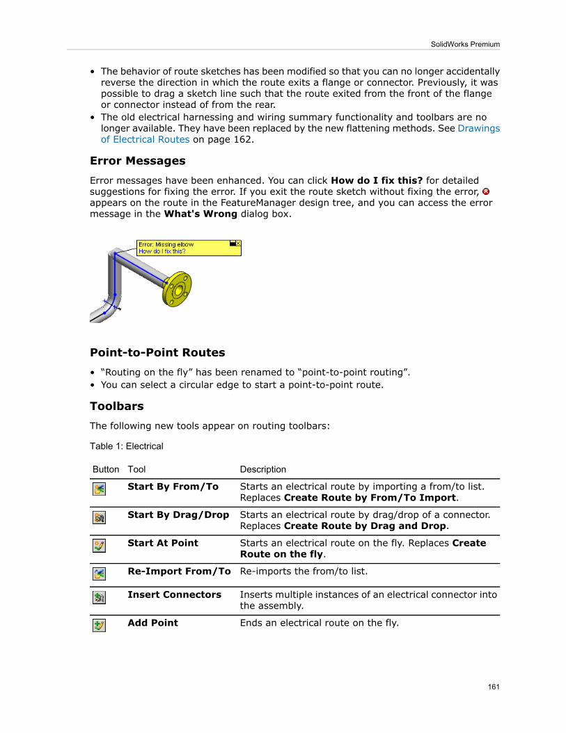
• The behavior of route sketches has been modified so that you can no longer accidentallyreverse the direction in which the route exits a flange or connector. Previously, it waspossible to drag a sketch line such that the route exited from the front of the flangeor connector instead of from the rear.
• The old electrical harnessing and wiring summary functionality and toolbars are nolonger available. They have been replaced by the new flattening methods. See Drawingsof Electrical Routes on page 162.
Error Messages
Error messages have been enhanced. You can click How do I fix this? for detailedsuggestions for fixing the error. If you exit the route sketch without fixing the error,appears on the route in the FeatureManager design tree, and you can access the errormessage in the What's Wrong dialog box.
Point-to-Point Routes
• “Routing on the fly” has been renamed to “point-to-point routing”.• You can select a circular edge to start a point-to-point route.
Toolbars
The following new tools appear on routing toolbars:
Table 1: Electrical
DescriptionToolButton
Starts an electrical route by importing a from/to list.Replaces Create Route by From/To Import.
Start By From/To
Starts an electrical route by drag/drop of a connector.Replaces Create Route by Drag and Drop.
Start By Drag/Drop
Starts an electrical route on the fly. Replaces CreateRoute on the fly.
Start At Point
Re-imports the from/to list.Re-Import From/To
Inserts multiple instances of an electrical connector intothe assembly.
Insert Connectors
Ends an electrical route on the fly.Add Point
161
SolidWorks Premium

Table 2: Flexible Tubing
DescriptionToolButton
Starts a tube route by drag/drop of a fitting. ReplacesCreate Route by Drag and Drop.
Start By Drag/Drop
Starts a tube route on the fly. Replaces Create Routeon the fly.
Start At Point
Adds a fitting to the route.Add Fitting
Ends a tube route on the fly.Add Point
Table 3: Piping
DescriptionToolButton
Starts a pipe route by drag/drop of a fitting. ReplacesCreate Route by Drag and Drop.
Start By Drag/Drop
Starts a pipe route on the fly. Replaces Create Routeon the fly.
Start At Point
Adds a fitting to the route.Add Fitting
Ends a pipe route on the fly.Add Point
Electrical Routes
Drawings of Electrical Routes
You can now create electrical drawings at the same time you flatten the 3D electricalroute assembly in the Flatten Route PropertyManager. You can include balloons andvarious electrical tables on the drawing. The tables are automatically placed so that theydo not overlap each other or the model geometry.
You can also add tables to drawings by clicking Insert > Tables > Electrical Tables.
Creating a Drawing
1. Open Routing\SensorEnclosure\routeAssy2-_Sensor Enclosure.sldasm.
2. Click Flatten Route (Electrical toolbar) or Routing > Electrical > Flatten Route.3. In the PropertyManager, under Flatten Options, select Display 3D Connectors.4. Select Create Electrical Drawing and select:
• Electrical BOM• Cut List• Connector Table• AutoBalloon
5. Click .
162
SolidWorks Premium

A flattened configuration is created in the route assembly file, and a drawing file iscreated. The drawing contains the tables and balloons you selected in thePropertyManager.
Keep the files open for the Highlight Search example below.
Highlight SearchYou can select text strings in an electrical (ECAD) drawing and search an electrical routeassembly for corresponding items.
Highlight Search enables you to capture a string of text from items such as importedschematic drawings or natively created electrical drawings. Then in an electrical routeassembly, you can search for corresponding 3D electrical items such as core wires, cables,assemblies, end connectors, and other electrical routing components. When HighlightSearch finds these items, they are highlighted in the graphics area and can be used foradditional finer searches.Activating Highlight Search
To activate Highlight Search:
1. In the Task Pane, select the Highlight Search tab .
2. Click to pin the Task Pane open.
Finding Components
To find a component:
1. In the Task Pane, under Text Capture, select Connector.2. In the graphics area of the drawing, zoom to the area shown below:
3. In the table, select the cell that contains the text Part:connector (3pin) female-2.The text appears in Search text in the Task Pane.
You can also type text in Search text.
4. In the Task Pane:
163
SolidWorks Premium

Click Find.The assembly becomes the active document, and a connector is highlighted in theFeatureManager design tree and graphics area. In the Task Pane, under Results,
a)
the full component name appears in Component name. Wires related to theconnector appear in Related wires/cables.
b) Click Zoom.The graphics area zooms to the highlighted connector.
You can also view the connector in the non-flattened view of the route.
5. In the FeatureManager design tree, right-click Route and select Showconfiguration.
6. Change the view to Isometric.7. In the Task Pane, click Find.
The connector is highlighted again.
8. In the Task Pane:a) In Related wires/cables, select 20gred_2@routeAssy2-_Sensor Enclosure.b) Click Find.The wire is highlighted in the graphics area.
ECAD Interfaces
You can import an AutoCad® Electrical, EPlan, or Mentor drawing and use the net list fromthat drawing to drive the creation of an electrical route in SolidWorks. You can import
the data by clicking Start By From/To (Electrical toolbar) or by dragging the net listinto an assembly.
Electrical Bills of Materials
Enhancements:
164
SolidWorks Premium

• The Electrical BOM and Cut List tables are now native SolidWorks tables. You canedit the tables to add and delete columns, and save the tables as templates.
• In the BOM, you can now access properties you add in custom columns in the cable/wirelibrary. To add a custom column to the cable/wire library, right-click an existing columnheader, select Insert, and then Column Right or Column Left.
TolAnalyst
Constructed FeaturesWhen you perform a tolerance study using TolAnalyst™, it now considers dimensions andtolerances you apply to constructed features with DimXpert for parts, and their effect onother features in the tolerance chain.
Affected Constructed Features:
• Intersect points• Intersect lines
165
SolidWorks Premium

Intersect Lines Example
Using TolAnalyst, you create a study to determine the tolerance stackfor a measurement defined from the plane on the right to the right-handhole, shown by the 11.18 reference dimension. The plane's location iscontrolled by two constructed features, intersect lines, shown by the redcircles.
The TolAnalyst study does not consider dimensionsand tolerances applied to constructed features. A
SolidWorks2008
warning message appears, indicating incompletetolerance chains.
For example, TolAnalyst does not consider thedimensions applied to the intersect line. The values20, 50, and 60 do not change. TolAnalyst does considerthe dimensions applied to the holes.
166
SolidWorks Premium

The TolAnalyst study considers dimensions andtolerances applied to the constructed features andholes. No warning messages appear.
The values 20, 50, and 60 change.
SolidWorks2009
Fixed and Floating Fastener AssembliesTolAnalyst can now consider the clearances resulting from fixed and floating fastenerassemblies when it computes the worst case tolerance conditions.
When you locate and constrain parts in assemblies using fasteners, the new Floatfasteners and pins option uses the clearances between the holes and fasteners toincrease the worst-case minimum and maximum result. Each part can move in an amountequal to the radial distance between the hole and fastener.
For fixed fastener assemblies, float applies to the part with clearance holes only. Forfloating fastener assemblies, float applies to both parts. You can also apply float to partsthat are located and constrained using hole–pin mating schemes.
Floating Fastener AssembliesFixed Fastener Assemblies
Bolts pass through both parts and are boundwith nuts.
Bolts pass through one part and arethreaded into another.
When to Consider Using Fastener Float• If the sole function of the clearance holes is to provide room for the fasteners, and theclearances are used to aid and provide adjustment to the assembly, using fastenerfloat is generally not recommended.
• If the clearance holes are also used to locate the parts, and you need to know theadverse effects the clearances allow, using fastener float is recommended.
Using Float in a Fixed Fastener AssemblyThis example illustrates the effects fastener float has on a measurement with partsconstrained by fixed fastener assemblies.
167
SolidWorks Premium

The measurement to evaluate is theminimum and maximum distancebetween the inner faces of the axlesupports.
The assembly includes axle supports that arefastened to the top plate using 10 mm bolts.
The top plate and axle supportshave these dimensions andtolerances.
Fixed Fastener Assembly Without Float
To evaluate the worst case scenario without considering fastener float:
1. Open TolAnalyst\Fixed\Castor.sldasm.
2. In the DimXpertManager , right-click Study1 and select Edit Feature.In the Result PropertyManager, under Analysis Parameters, note that Floatfasteners and pins is cleared. Float is not considered. Under Analysis Summary,the Min is 48.5 and the Max is 51.5, for a total range of 3mm.
168
SolidWorks Premium

To achieve the worstcase minimum, given thetop plate's threaded holediameter 0.5 positiontolerance, TolAnalystsimulates the 105 basicdimension between thethreaded holes at 104.5.
For the axle supports,when TolAnalystsimulates the clearanceholes at their LMC size of11.5, the resultantposition tolerance is 1.0,enabling the 27.5 basicdimension from datum Bto the holes to becalculated at 28.
Assembling the parts with the fastener float option cleared, TolAnalystaligns the clearance holes in the axle supports concentrically with thethreaded holes in the top plate, resulting in a worst case minimum of48.5.
Fixed Fastener Assembly With Float
To evaluate the worst case scenario considering fastener float:
• In the PropertyManager, select Float fasteners and pins under Analysis Parameters.The worst case minimum decreases to 47 while the worst case maximum increases to53. The total range of 6mm is double the range of that without fastener float.
169
SolidWorks Premium

To achieve the worst case minimum result, TolAnalyst calculates theparts as described in the procedure where float is not considered. SeeFixed Fastener Assembly Without Float on page 168. When the parts areassembled, the axle supports are pushed inward (as shown by the redarrows below) until the clearance holes make contact with the bolts,resulting in a minimum worst case of 47.
Using Float in a Floating Fastener AssemblyThis example illustrates the effects fastener float has on a measurement with partsconstrained by floating fastener assemblies.
The measurement to evaluate is theminimum and maximum distancebetween the inner faces of the axlesupports.
The assembly includes axle supports fastenedto the top plate using 10 mm bolts.
170
SolidWorks Premium

The top plate and axle supportshave these dimensions andtolerances.
Floating Fastener Assembly Without Float
To evaluate the worst case scenario without considering fastener float:
1. Open TolAnalyst\Floating\Castor.sldasm.
2. In the DimXpertManager , right-click Study1 and select Edit Feature.In the Result PropertyManager, under Analysis Parameters, note that Floatfasteners and pins is cleared. Float is not considered. Under Analysis Summary,the Min is 48 and the Max is 52, for a total range of 4mm.
171
SolidWorks Premium

To achieve the worstcase minimum,TolAnalyst calculatesthe top plates clearanceholes at their LMC sizeof 11, resulting in aposition tolerance of 1.TolAnalyst can thensimulate the 105 basicdimension between theholes at 104.
For the axle supports,when TolAnalystcalculates the clearanceholes at their LMC sizeof 11, the resultantposition tolerance is 1.0,enabling the 27.5 basicdimension from datumB to the holes to becalculated at 28.
Assembling the parts with the fastener float option cleared, TolAnalystaligns the clearance holes in the axle supports concentrically with thethreaded holes in the top plate, resulting in a worst case minimum of48.
Floating Fastener Assembly with Float
To evaluate the worst case scenario considering fastener float:
• In the PropertyManager, select Float fasteners and pins under Analysis Parameters.The worst case minimum decreases to 46 while the worst case maximum increases to54. The total range of 8mm is double the range for when TolAnalyst did not considerfastener float.
172
SolidWorks Premium

To achieve the worst case minimum result, TolAnalyst simulates the partsas described in the procedure where float is not considered. See FloatingFastener Assembly Without Float on page 171. When the parts areassembled, the axle supports are pushed up against the inside faces ofthe top plate's clearance holes, and to the outside faces of the axlesupports' clearance holes, resulting in a worst case minimum of 46.
173
SolidWorks Premium