
What's New in Pro/ENGINEER Wildfire 4 - Pretech · PDF fileProduct What's New Pro/ENGINEER...
262
Product What's New : Pro/ENGINEER Wildfire 4.0 View by Package ● Pro/ENGINEER Advanced Assembly (4) ● Pro/ENGINEER Advanced Mechanica (5) ● Pro/ENGINEER Advanced Rendering (5) ● Pro/ENGINEER Behavioral Modeling (1) ● Pro/ENGINEER Cabling Design (6) ● Pro/ENGINEER Computer-Aided Verification (3) ● Pro/ENGINEER Foundation XE (113) ● Pro/ENGINEER Interactive Surface Design (4) ● Pro/ENGINEER Interface for Unigraphics with ATB (1) ● Pro/ENGINEER Mechanica (21) ● Pro/ENGINEER Piping Design (4) ● Pro/ENGINEER Prismatic and Multi-surface Milling (11) ● Pro/ENGINEER Production Machining (3) ● Pro/ENGINEER Reverse Engineering (8) ● Pro/ENGINEER Tool Design (1) View by Functional Area ● 2D Interface (2) ● 3D Interface (4) ● Assembly (19) ● Cabling Design (6) ● Detail Drawing (23) ● ECAD (2) ● Fundamentals & Pro/PROGRAM (12) ● Import Data Doctor (1) ● Manufacturing (GPOST, Vericut) (2) ● Manufacturing (NC, Expert Machinist) (15) ● ModelCHECK (2) ● Mold Design & Casting (1) ● Other Functional Areas (16) ● Part Modeling (26) ● Piping (Spec Driven & Non-Spec Driven) (4) ● Rendering (7) ● Sheetmetal Design and Manufacturing (5) ● Simulation - Behavorial Modeling (1) ● Simulation - Mechanism Design & Dynamics (4) ● Simulation - Structural & Thermal (26) ● Surfacing - Facet Modeling (8) ● Surfacing - ISDX (4) Copyright © 2007 Parametric Technology Corporation
Transcript of What's New in Pro/ENGINEER Wildfire 4 - Pretech · PDF fileProduct What's New Pro/ENGINEER...

Product What's New : Pro/ENGINEER Wildfire 4.0
View by Package
● Pro/ENGINEER Advanced Assembly (4) ● Pro/ENGINEER Advanced Mechanica (5) ● Pro/ENGINEER Advanced Rendering (5) ● Pro/ENGINEER Behavioral Modeling (1) ● Pro/ENGINEER Cabling Design (6) ● Pro/ENGINEER Computer-Aided Verification (3) ● Pro/ENGINEER Foundation XE (113) ● Pro/ENGINEER Interactive Surface Design (4) ● Pro/ENGINEER Interface for Unigraphics with ATB (1) ● Pro/ENGINEER Mechanica (21) ● Pro/ENGINEER Piping Design (4) ● Pro/ENGINEER Prismatic and Multi-surface Milling (11) ● Pro/ENGINEER Production Machining (3) ● Pro/ENGINEER Reverse Engineering (8) ● Pro/ENGINEER Tool Design (1)
View by Functional Area
● 2D Interface (2) ● 3D Interface (4) ● Assembly (19) ● Cabling Design (6) ● Detail Drawing (23) ● ECAD (2) ● Fundamentals & Pro/PROGRAM (12) ● Import Data Doctor (1) ● Manufacturing (GPOST, Vericut) (2) ● Manufacturing (NC, Expert Machinist) (15) ● ModelCHECK (2) ● Mold Design & Casting (1) ● Other Functional Areas (16) ● Part Modeling (26) ● Piping (Spec Driven & Non-Spec Driven) (4) ● Rendering (7) ● Sheetmetal Design and Manufacturing (5) ● Simulation - Behavorial Modeling (1) ● Simulation - Mechanism Design & Dynamics (4) ● Simulation - Structural & Thermal (26) ● Surfacing - Facet Modeling (8) ● Surfacing - ISDX (4)
Copyright © 2007 Parametric Technology Corporation

Product What's New
Pro/ENGINEER Advanced Assembly
Assembly Process Planning Improvement In Assembly Process Planning, also referred to as Pro/PROCESS for Assemblies, you can start the process planning sequence with a fully assembled design model.
Breaking Dependencies in Reference Viewer You can now break certain dependencies using the Reference Viewer.
New Reference Viewer The Reference Viewer has a new consolidated user interface with expanded functionality.
Replace Unrelated Components You can replace a component with an unrelated part or subassembly. Pro/ENGINEER provides the tools to map the references required from both objects to ensure that there is no feature failure due to missing references.

Product What's New
Pro/ENGINEER Advanced Mechanica
Contacts and Infinite Friction Contact analysis now includes the ability to specify infinite friction between the contacting surfaces.
External Coefficient Field A pressure load field can be imported through an external .fnf (FEM neutral file) file.
Isolate for Exclusion AutoGEM Control (IEAC) In integrated mode, you can exclude elements in areas of singularities using the Isolate for Exclusion AutoGEM Control (IEAC).
Nonlinear Materials Nonlinear (hyperelastic) materials are supported for large deformation analysis.
Thermal Resistance Interface Thermal Resistance interface is available.

Product What's New
Pro/ENGINEER Advanced Rendering
Color Temperature You can set the color temperature of a light source.
Environment Lighting You can render models using only a HDRI (High Dynamic Range Image) as a light source.
Expanded Graphics Library The Graphics Library with Pro/ENGINEER includes new scene files and improved Photolux materials.
Illuminance Units Added Seven illuminance units have been added to Pro/ENGINEER Wildfire to affect the intensity of light.
Skylight Lighting Skylight lighting has been added to Pro/ENGINEER Wildfire.

Product What's New
Pro/ENGINEER Behavioral Modeling
External Analysis Non-toolkit based, external analysis is now available.

Product What's New
Pro/ENGINEER Cabling Design
Auto Route Shields Cable shields are automatically routed.
Cable Locations with Missing References You can fix cable locations that fail regeneration due to lost references
Checking Network Continuity There are new tools to identify non continuous networks and to automatically merge overlapping location network breaks.This improves the success of autorouting.
External Representations with Cabling Design You can use external representation with Cabling design.
Improved Subharness Control You can rename, color, and place subharnesses on a layer.
Routing Ribbon Cables You can route ribbon cables

Product What's New
Pro/ENGINEER Computer-Aided Verification
Pro/CMM with Pro/NC User Model Pro/CMM and Pro/NC use a common user model.
Scanning for Pro/CMM Pro/CMM support s canning probe and measured points.
Theoretical Elements in Pro/CMM You can create theoretical (nonmeasured) elements in Pro/CMM.

Product What's New
Pro/ENGINEER Foundation XE
2D Wizards Enhancements Pro/ENGINEER Wildifre 4.0 introduces new enhancements to several of the 2D Import and Export Wizards.
Absolute Accuracy for Sheet Metal Parts Absolute accuracy is the default for all new sheet metal parts.
Active Layer in 3D You can activate a layer in a 3D model so that all newly created objects are automatically placed in that layer.
Allow Limited Visibility in Unfolded Views You can set the visible area of an unfolded view to Full view, Half view, Partial view, or Broken view. You can convert any broken view back to a full view.
Annotation Orientation Definition For any created 3D Annotation, the Active Orientation Annotation dialog box helps you to define the planar space, text direction, and viewing angle. In this dialog box you can set the orientation by datum plane, flat surface, or named view.
Assembly Control of Part Layers You can control component-level layers at the assembly level without changing the display status of the sub models. You do not have to save the sub models to save the display status at the assembly level.
Assembly Model Tree Enhancements The Assembly Model Tree is improved.
Assigning Bend Notes to Annotation Planes Annotation planes are supported for bend notes.
Associative Annotation Placement The position of annotations in 2D drawing views is associated to the position of the annotations in the 3D model.
Asynchronous Curve Creation

You can create composite curves using Copy and Paste after pausing the dashboard.
Auto Round Tool The new Auto Round Feature creates Round features automatically in your model. These Round features are referred to as Auto-Round Members (ARMs).
AutoCAD DXF and DWG Enhancements Several enhancements to Pro/ENGINEER's Interface for AutoCAD are introduced including upgraded support for AutoCAD 2005 and AutoCAD 2006 formats.
Automated On-Demand Simplified Representations On Demand is now active when a Simplified Representation is active.
Automatic Creation of Diameter Dimensions in Sketcher You can automatically create diameter dimensions in Sketcher.
Automatic Locking of User Defined Dimensions User defined dimensions in sketcher can be automatically locked.
Automatic Model Fixes with ModelUPDATE Mode ModelCHECK now includes a ModelUPDATE mode.
AVI Format in Playbacks AVI is now an available format for capturing an analysis playback.
Bill of Material (BOM) Balloon Support for Flexible Components and Family Tables You can now create BOM balloons for Flexible components, Bulk items, Included items, and Family table top generics
Capture Layer Visibility Status in Combined States When creating or redefining a Combined State, click the include layer status checkbox to capture the visibility status of all current layers.
Control of View Name Placement You can control the location of a drawing view name by using a drawing setup option.
Controlling Leading and Trailing Zeroes for Geometric Tolerances In drawings, the drawing setup option gtol_lead_trail_zeros controls leading and trailing zeroes for geometric tolerances (GTOLs). This setting for GTOLS is independent of what is set for dimensions using the drawing setup option lead_trail_zeroes.

Copying and Pasting Parameters You can copy a parameter definition and paste it into another model or context.
Correct Display of Tapered Threads in Drawings Simplified drawing representation of new tapered threads is available, according to the ANSI, ISO, and JIS drawing standards.
Creating Zones Using an Offset Coordinate System You can create zones by defining offsets from a coordinate system.
Creating Zones Using an Offset Coordinate System You can create zones by defining offsets from a coordinate system.
Damper Objects as Pro/ENGINEER Features Damper objects are now Pro/ENGINEER features.
Datum Tag Placement in Drawings Tag placement for set datums attached to Geometric Tolerances (GTOLs) is controlled by where you click on the GTOL to place the tag.
Default Placement for Surface Finish A new configuration option sets the default placement type for surface finish annotations within the Surface Finish dialog box
Delete Missing References using the Reference Viewer You can delete individual references from the Reference Viewer when there is a failure or when you decide against using the reference.
Delete or Suppress Individual Group Members You can delete or suppress an individual feature embedded within a group without ungrouping the group first.
Displaying the Active Model Activating a model within an assembly dims all inactive models.
Draft Datum Improvements You can create parametric draft datums using the Vertex or On Entity options. The leader and elbow segments of a set datum tag are independently controlled and adjustable.
Draft Features on Open Surfaces You can create Draft features on open surfaces

Dragging and Dropping Operations in the Model Tree Dragging and Dropping Operations in the Model Tree are improved.
Driving Dimension Annotation Elements The driving dimensions of your model can appear as 3D annotations.
Dynamic Placement of Textures You can dynamically position and orient textures on a model. .
Enhanced Hole Tool Enhancements to the Hole tool include tapered holes and threads, simple holes with counterbores, countersinks and point angles, and format control for hole types.
Enhancements to Annotation Feature User Interface You can create annotation elements more efficiently, gain better control over references, and easily change the active annotation orientation.
Enhancements to Cosmetic Threads You can create tapered cosmetic threads.
Enhancements to the Parameters Dialog Box. In the Parameters dialog box, you can move rows up and down to help organize parameters for an object.
Exact Expressions You can use the syntax =( ) to force Pro/ENGINEER to calculate the precise value of the expression without the need for a relation.
Expanded Basis for a Mirroring Operation When mirroring draft entities in a drawing, you can select any straight entity as the mirror plane. Previously, you could use straight draft lines and straight construction lines.
Extension Lines for Symbols Attached to Draft Entities You can drag a symbol or surface finish off a straight draft entity or straight model curve, and create extension lines.
External Simplified Representation (ESR) Enhancements You can assemble components and create features in an External Simplified Representation and create simplified representations of an external simplified representation.
File Open Dialog Enhancements

Navigation and Retrieval in the File Open dialog box is easier.
Finding Annotation Elements with Missing References Use ModelCHECK or the Search Tool to collect Annotation Elements with missing references
Flat-to-Screen Annotation Plane You can place annotations on an annotation plane that remains flat to the screen even during model rotation.
Flipping Orientation for Insert, Axis Alignment, and Motion Axis. You can flip the orientation of insert and axis align constraints and the orientation of an entire (motion) connection.
Geometric Tolerance (GTOL) Enhancements You can add additional text to the GTOL definition. You can also use the Copy From option to duplicate an existing GTOL.
Handling Invalid and Missing References in Sketcher You can replace invalid and missing references for sketches in Sketcher.
Help Center Improvements The Pro/ENGINEER Help Center has been improved in content, navigation, and search mechanism.
Heterogeneous Design in Context Heterogeneous Design in Context helps provide companies with data managed use of multi-cad data in Pro/ENGINEER.
Import DataDoctor Improvements The Import DataDoctor (IDD) environment provides tools for repair or reuse of your imported data.
Improved Conversion to Draft Entities Model edges more efficiently convert to multiple draft types such as Draft lines, Draft arcs, Draft splines, and Draft ellipses
Improved ModelCHECK Parameter Management ModelCHECK edits parameters only when necessary.
Improved Performance when Importing Holes The performance when importing boards containing a large number of holes is improved.
Improved Sharing of User-Defined Wall Sections

You can store user-defined wall sections for reuse on other parts.
Improved Swept Blend You can add a normal to plane constraint on a Swept Blend.
Improvements to Basic Dimension Types When text is added to basic dimensions such as a prefix or suffix), the content appears outside of the basic dimension box.
Improvements to Cross Hatching in Drawings Cross hatches in drawings have greater flexibility. You can use the same workflow for controlling section attributes for 2D sketches and 2D sections. You can also control the visibility of entire sections, components, or component areas. You can hatch or fill flat surfaces. You can control hidden line removal (HLR) for surface and 2D section crosshatches, and control default visibility of crosshatches for 2D and 3D sections.
Incremental Update and Design Collaboration You can incrementally update printed circuit board (PCB) outline and component information. By cross-highlighting objects with reference designs between Pro/ENGINEER and InterComm Expert, live MCAD/ECAD collaboration sessions are possible.
Intent Objects as Sketcher References Intent objects are supported as sketcher references.
Intent Objects Enhancements You can use Intent Objects in more areas and there are more types of intent objects.
Interface for ProductView Enhancement The Interface for ProductView now supports the import of ProductView data as exact representation geometry.
Line Style and Color for Sketched Entities You can assign a line style and color to sketched entities
Mapkey Enhancements Mapkey recording for relations and selection filters is improved.
Mathcad - Pro/ENGINER Integration Enhancements In Pro/ENGINEER Wildfire 4.0, new Mathcad compatibility and other enhancements are provided.
Merge Features Accept Multiple Quilts

You can use the Merge feature to merge more than two quilts
Modify Model Edges in Drawings You can alter the display of model edges directly in drawings.
New Interface for JT PTC introduces a new Interface for JT module for Pro/ENGINEER Wildfire 4.0.
New Method for Positioning Walls in Sheet Metal Mode Sheet Metal mode includes an Add to Part Edge option for locating walls.
Offset Notes to Reference Points and Axes You can create an offset note referencing datum points and axes in a drawing. You can create Hole table callouts that are either offset or on-axis, and remain offset during geometry modifications.
One-by-One Chain Selection It is easier to select one-by-one chains.
Ordinate Dimensions in 3D Models You can create ordinate dimension sets as 3D annotations.
Parameter and Relations User Interface in Mechanism Design. The parameter and relations user interfaces are now in Mechanism Design.
Pattern Enhancements The Pattern tool is more consistent with other dashboard tools.
PDF Enhancements Several improvements to the Interface for PDF are introduced including support for generation of 3D PDF content.
Redefinition Options for Features with External References New options are available while redefining features disconnected from their external references.
Reference Handle Visibility When placing features that require reference handles, such as Holes or Datum Axes, the offset reference handles are different than the handles you use for resizing and reorienting.
Referencing by Intent Name You can create intent objects using a query that searches by intent name.

Remove Feature The new Remove Feature allows user to remove surface geometry from models for downstream uses like structural analysis or casting creation.
Reorient Driven Dimension Annotations You can reorient driven dimensions that have been created using two points, without redefining.
Replace Unrelated Components You can replace a component with an unrelated part or subassembly. Pro/ENGINEER provides the tools to map the references required from both objects to ensure that there is no feature failure due to missing references.
Restored Features Performance It takes less time to restore the features in a model after canceling a feature redefinition.
Restricted Parameter Enhancements There are enhancements to restricted parameter definitions.
Retain Last Used Annotation Orientation The definition of planar space, text direction, and viewing angle of a 3D annotation are captured in a single definition of the active annotation orientation. This definition establishes the orientation for any newly created annotations.
Retrieving Family Table Instances is Faster Retrieving assemblies that contain Family Table Instances is now faster. This is due to improvements in Instance accelerator files, and in the retrieval of nested Family Table Instances and Instance dependencies.
Saving Models in a Clipped State You can save a model in a clipped state.
Selecting Silhouette Edges of Non-Analytic Surfaces In Drawing mode you can reference the silhouette edges that are created by non analytic surfaces.
Set Datum Tag Improvements in Drawings You can attach draft set datum tags to model arcs, model circles, draft arcs, and draft circles.
Setting for Displayed Significant Digits The detail setup option, dim_trail_zero_max_places, sets the number of decimal places when trailing zeroes are used to reach the number of decimal places set by configuration option, default_dec_places.
Sheet Metal Thickness is a Part Parameter The thickness of sheet metal parts is controlled by a new part-level parameter.
Shell Geometry Enhancements You can create more robust geometry using the Shell feature.
Shortcut to Layer Commands The following layer commands are removed from the Visibility menu (View > Visibility) and relocated under Layer in the Layer Tree: Isolate, Hidden Line, Copy Status From, and Drawing Dependent.
Show Full Part Names in the Graphics Window When a part is activated in an assembly, you can see the entire part name in the Graphics window.
Shrinkwrap Feature Enhancements Shrinkwrap features regenerate faster and remain associated with the Simplified Representation or Family Table instance in which they were created or redefined. Surface selection is simplified.
Simplified Representation Preview You can preview a simplified representation before you open it.
Simplified Representation Support in Family Table Instances. You can create Simplified Representations of Assembly Family Tables instances in the same way that you create a simplified representation of an assembly. The simplified representation can now be created in the actual instance.
Sketcher Diagnostics Sketcher diagnostic tools are added to help you understand issues in your sketch real-time.
Snapping a Room to the Model Any aspect of a room can be snapped to the model.
Spring Objects as Pro/ENGINEER Features Spring objects are now Pro/ENGINEER features.
Starting Pro/TOOLKIT Applications from Distributed Pro/BATCH Distributed Pro/BATCH has been extended to allow batch execution of custom Pro/TOOKLIT applications.
Superscripted Symmetric Tolerance Display You can set symmetric tolerances to appear superscripted from the nominal dimension value.

Surface Profile Geometric Tolerance Comply with Standard You can create a surface profile geometric tolerance (GTOL) in accordance with the Y14.41 standard. This enables an unequal disposition of the tolerance zone.
Surface Reference for Driven Dimensions When creating driven 3D dimensions, you can use both surface references and traditional edge references.
Toggle Display of Annotations You can quickly turn on and off the display of all 3D annotations.
Transparent Display Style There is a new transparent display style for components.
UDF Enhancements Previewing User-Defined Features (UDFs) is enhanced. Hidden status is maintained in the target object.
Undoing and Redoing View Orientation States in Sketcher Undo and Redo commands are available for view orientation states in Sketcher.
Updates to Active Layers Objects maintain their active layer status as you navigate between open windows. When a layer is activated, layers with the same name are activated in any sub-models.
User-Defined Feature (UDF) Replacement Improvements You can replace a UDF with a family table instance and preserve the IDs of those objects included in the UDFs that are common. This results in successful feature regeneration downstream.
Visual Basic Application Programming Interface (API) Pro/ENGINEER Wildfire 4.0 introduces a new programming interface for Visual Basic.
Witness Line and Arrow Options for 3D Dimensions You can alter witness lines and arrow options for 3D dimensions.

Product What's New
Pro/ENGINEER Interactive Surface Design
Style Curve Tuning The Style curve creation and editing tools are enhanced
Style in Assembly Style is available for assembly-level features
Style Tree The Style feature has a sub-feature tree, listing each entity in the feature
Surface Edit You can use the Style feature to directly edit a surface by pulling on a control mesh

Product What's New
Pro/ENGINEER Interface for Unigraphics with ATB
Unigraphics Support Upgraded support for import and export of UG parts and assemblies.

Product What's New
Pro/ENGINEER Mechanica
Assembly Connectivity Manager Interfaces are created through a common dialog box.
AutoGEM Max Element Size for Mesh Control You can control the maximum size of elements for mesh created by the AutoGEM mesh generator in particular areas of a model.
AVI Format Available in Movie Export AVI format is now available for the export of movies.
Bearing Load, Heat Load, and Convection Coefficient Improvements Dialog boxes for Bearing Loads, Heat Loads, and Convection Coefficients have been improved.
Collector Style Selection Reference selection in Mechanica is consistent with standard mode.
Component-Component Interface Assignment Component-Component has been added as a reference type for creating interfaces.
Default Interface You can select a default interface type between components in an assembly.
Dynamic Query on Capping and Cutting Surfaces Dynamic query is available with capping and cutting surfaces.
Enhanced Assembly Modeling Faster, more accurate modeling of compressed assemblies is possible.
Enhanced Viewing of Results Geometry Greater control over area of viewing in Mechanica results.
Exploded Views in Results You can view results of assemblies in an exploded state in Pro/ENGINEER Mechanica.
Improved Diagnostics
A diagnostics tool helps in identifying issues with models.
Improvements to Meshing for Simple Models Curvature-based, AutoGEM mesh controls improve meshing for simple models.
Loads Propagated from Part to Assembly Level You can propagate loads and constraints from the part level to the assembly level.
Location in Dynamic Query You can view coordinates for the position of the dynamic query.
Merged Installation Pro/ENGINEER Mechanica now installs as a component of Pro/ENGINEER.
Model Connectivity You can preview interface types between components in an assembly.
Model Tolerance Enhancements Enhancements to the model tolerance report make it easier to understand where problems are introduced.
Offset Shells for FEM Mode Shells that are not compressed to the midsurface are exported with an offset to NASTRAN.
Resultant Measures Resultant measures, previously only in standalone Mechanica, are available in integrated mode.
Results Legend Editing Greater control over customizing the results legend significantly improves your ability to format your results to match your own specifications and needs.

Product What's New
Pro/ENGINEER Piping Design
Display Routing Environment Information in the Graphics Window The active routing environment appears in the Graphics window.
External Representations with Piping Design You can use external representation with Piping design
Lightweight Pipe Representation A lightweight representation for thick pipes improves design performance
Weld Control in Specification-Driven Piping You can insert welds on cuts and fitting ports, and export the weld information to a *.pcf file

Product What's New
Pro/ENGINEER Prismatic and Multi-surface Milling
Automatic Creation of Workpieces You can automatically create a manufacturing workpiece based on the reference model envelope.
Corner Finishing Tool Path You can automatically remove the remaining material in corners and valleys with the Corner Finishing tool path.
Degouging of the Tool Holder You can degouge the tool holder during the computation of the tool path.
Direct Output of NURBS Interpolation You can generate output of NURBS Interpolation for cutting motions
G-POST Version 6.1 G-POST version 6.1 has been integrated into Pro/ENGINEER.
Improved Quality for Surface Finishes You can conontrol the quality of surface finishes with parameters MAX_SEGMENT_LENGHT and POINT_DISTRIBUTION.
Machine Kinematics Simulation Automated collision checking and machine kinematics for NC and CMM tool path simulation is now available.
Manufacturing Components Toolbar A Manufacturing Components toolbar simplifies the definition of manufacturing models
NC and CMM Parameters Setup User Interface The redesign of the NC and CMM Parameters Setup dialog box simplifies the definition of tool paths.
Roughing, Re-roughing, and Finishing Tool Paths In the Process Manager, you can directly create the roughing, re-roughing, and finishing tool paths
VERICUT Version 6.0 VERICUT Version 6.0 has been integrated into Pro/ENGINEER.

Product What's New
Pro/ENGINEER Production Machining
3-Axis Trajectory in the Process Manager You can create a customizable step for a 3-axis trajectory mill in the Process Manager.
Customizable Names for Table Headers You can customizable header names in the Process Table for manufacturing.
Turn Profile User Interface You can define a Turn Profile using a dashboard user interface.

Product What's New
Pro/ENGINEER Reverse Engineering
Creation of Symmetry Planes You can create a symmetry plane on the facet geometry.
Display of Outlier points The display of outlier points are now previewed
Filling of Holes The definition and display of holes for filling in facet models is much improved.
Offsetting and Thickening of Facets You can offset and thicken facet models.
Point Phase Performance The displaying and filtering of points while you manipulate a large point cloud has improved.
Return to the Points Phase You can return to the Point Phase from the Wrap Phase in Facet modeling.
Selection of Connected Facets You can select all connected facets in one command.
Trimming Facets by a Plane You can trim facets by a datum plane.

Product What's New
Pro/ENGINEER Tool Design
Color Assignment for Split Surfaces Colors are assigned automatically to Split and Slider surfaces during component extraction.

Product What's New
2D Interface
2D Wizards Enhancements Pro/ENGINEER Wildifre 4.0 introduces new enhancements to several of the 2D Import and Export Wizards.
AutoCAD DXF and DWG Enhancements Several enhancements to Pro/ENGINEER's Interface for AutoCAD are introduced including upgraded support for AutoCAD 2005 and AutoCAD 2006 formats.

Product What's New
3D Interface
Interface for ProductView Enhancement The Interface for ProductView now supports the import of ProductView data as exact representation geometry.
New Interface for JT PTC introduces a new Interface for JT module for Pro/ENGINEER Wildfire 4.0.
PDF Enhancements Several improvements to the Interface for PDF are introduced including support for generation of 3D PDF content.
Unigraphics Support Upgraded support for import and export of UG parts and assemblies.

Product What's New
Assembly
Assembly Control of Part Layers You can control component-level layers at the assembly level without changing the display status of the sub models. You do not have to save the sub models to save the display status at the assembly level.
Assembly Model Tree Enhancements The Assembly Model Tree is improved.
Assembly Process Planning Improvement In Assembly Process Planning, also referred to as Pro/PROCESS for Assemblies, you can start the process planning sequence with a fully assembled design model.
Automated On-Demand Simplified Representations On Demand is now active when a Simplified Representation is active.
Breaking Dependencies in Reference Viewer You can now break certain dependencies using the Reference Viewer.
Capture Layer Visibility Status in Combined States When creating or redefining a Combined State, click the include layer status checkbox to capture the visibility status of all current layers.
Creating Zones Using an Offset Coordinate System You can create zones by defining offsets from a coordinate system.
Creating Zones Using an Offset Coordinate System You can create zones by defining offsets from a coordinate system.
Displaying the Active Model Activating a model within an assembly dims all inactive models.
External Simplified Representation (ESR) Enhancements You can assemble components and create features in an External Simplified Representation and create simplified representations of an external simplified representation.
Flipping Orientation for Insert, Axis Alignment, and Motion Axis.
You can flip the orientation of insert and axis align constraints and the orientation of an entire (motion) connection.
New Reference Viewer The Reference Viewer has a new consolidated user interface with expanded functionality.
Replace Unrelated Components You can replace a component with an unrelated part or subassembly. Pro/ENGINEER provides the tools to map the references required from both objects to ensure that there is no feature failure due to missing references.
Replace Unrelated Components You can replace a component with an unrelated part or subassembly. Pro/ENGINEER provides the tools to map the references required from both objects to ensure that there is no feature failure due to missing references.
Retrieving Family Table Instances is Faster Retrieving assemblies that contain Family Table Instances is now faster. This is due to improvements in Instance accelerator files, and in the retrieval of nested Family Table Instances and Instance dependencies.
Shrinkwrap Feature Enhancements Shrinkwrap features regenerate faster and remain associated with the Simplified Representation or Family Table instance in which they were created or redefined. Surface selection is simplified.
Simplified Representation Preview You can preview a simplified representation before you open it.
Simplified Representation Support in Family Table Instances. You can create Simplified Representations of Assembly Family Tables instances in the same way that you create a simplified representation of an assembly. The simplified representation can now be created in the actual instance.
Transparent Display Style There is a new transparent display style for components.

Product What's New
Cabling Design
Auto Route Shields Cable shields are automatically routed.
Cable Locations with Missing References You can fix cable locations that fail regeneration due to lost references
Checking Network Continuity There are new tools to identify non continuous networks and to automatically merge overlapping location network breaks.This improves the success of autorouting.
External Representations with Cabling Design You can use external representation with Cabling design.
Improved Subharness Control You can rename, color, and place subharnesses on a layer.
Routing Ribbon Cables You can route ribbon cables

Product What's New
Detail Drawing
Allow Limited Visibility in Unfolded Views You can set the visible area of an unfolded view to Full view, Half view, Partial view, or Broken view. You can convert any broken view back to a full view.
Associative Annotation Placement The position of annotations in 2D drawing views is associated to the position of the annotations in the 3D model.
Bill of Material (BOM) Balloon Support for Flexible Components and Family Tables You can now create BOM balloons for Flexible components, Bulk items, Included items, and Family table top generics
Control of View Name Placement You can control the location of a drawing view name by using a drawing setup option.
Controlling Leading and Trailing Zeroes for Geometric Tolerances In drawings, the drawing setup option gtol_lead_trail_zeros controls leading and trailing zeroes for geometric tolerances (GTOLs). This setting for GTOLS is independent of what is set for dimensions using the drawing setup option lead_trail_zeroes.
Correct Display of Tapered Threads in Drawings Simplified drawing representation of new tapered threads is available, according to the ANSI, ISO, and JIS drawing standards.
Datum Tag Placement in Drawings Tag placement for set datums attached to Geometric Tolerances (GTOLs) is controlled by where you click on the GTOL to place the tag.
Draft Datum Improvements You can create parametric draft datums using the Vertex or On Entity options. The leader and elbow segments of a set datum tag are independently controlled and adjustable.
Expanded Basis for a Mirroring Operation When mirroring draft entities in a drawing, you can select any straight entity as the mirror plane. Previously, you could use straight draft lines and straight construction lines.

Extension Lines for Symbols Attached to Draft Entities You can drag a symbol or surface finish off a straight draft entity or straight model curve, and create extension lines.
Geometric Tolerance (GTOL) Enhancements You can add additional text to the GTOL definition. You can also use the Copy From option to duplicate an existing GTOL.
Improved Conversion to Draft Entities Model edges more efficiently convert to multiple draft types such as Draft lines, Draft arcs, Draft splines, and Draft ellipses
Improvements to Basic Dimension Types When text is added to basic dimensions such as a prefix or suffix), the content appears outside of the basic dimension box.
Improvements to Cross Hatching in Drawings Cross hatches in drawings have greater flexibility. You can use the same workflow for controlling section attributes for 2D sketches and 2D sections. You can also control the visibility of entire sections, components, or component areas. You can hatch or fill flat surfaces. You can control hidden line removal (HLR) for surface and 2D section crosshatches, and control default visibility of crosshatches for 2D and 3D sections.
Modify Model Edges in Drawings You can alter the display of model edges directly in drawings.
Offset Notes to Reference Points and Axes You can create an offset note referencing datum points and axes in a drawing. You can create Hole table callouts that are either offset or on-axis, and remain offset during geometry modifications.
Reorient Driven Dimension Annotations You can reorient driven dimensions that have been created using two points, without redefining.
Selecting Silhouette Edges of Non-Analytic Surfaces In Drawing mode you can reference the silhouette edges that are created by non analytic surfaces.
Set Datum Tag Improvements in Drawings You can attach draft set datum tags to model arcs, model circles, draft arcs, and draft circles.
Setting for Displayed Significant Digits The detail setup option, dim_trail_zero_max_places, sets the number of decimal places when trailing

zeroes are used to reach the number of decimal places set by configuration option, default_dec_places.
Shortcut to Layer Commands The following layer commands are removed from the Visibility menu (View > Visibility) and relocated under Layer in the Layer Tree: Isolate, Hidden Line, Copy Status From, and Drawing Dependent.
Superscripted Symmetric Tolerance Display You can set symmetric tolerances to appear superscripted from the nominal dimension value.
Updates to Active Layers Objects maintain their active layer status as you navigate between open windows. When a layer is activated, layers with the same name are activated in any sub-models.

Product What's New
ECAD
Improved Performance when Importing Holes The performance when importing boards containing a large number of holes is improved.
Incremental Update and Design Collaboration You can incrementally update printed circuit board (PCB) outline and component information. By cross-highlighting objects with reference designs between Pro/ENGINEER and InterComm Expert, live MCAD/ECAD collaboration sessions are possible.

Product What's New
Fundamentals & Pro/PROGRAM
Dragging and Dropping Operations in the Model Tree Dragging and Dropping Operations in the Model Tree are improved.
Enhancements to the Parameters Dialog Box. In the Parameters dialog box, you can move rows up and down to help organize parameters for an object.
Exact Expressions You can use the syntax =( ) to force Pro/ENGINEER to calculate the precise value of the expression without the need for a relation.
File Open Dialog Enhancements Navigation and Retrieval in the File Open dialog box is easier.
Finding Annotation Elements with Missing References Use ModelCHECK or the Search Tool to collect Annotation Elements with missing references
Help Center Improvements The Pro/ENGINEER Help Center has been improved in content, navigation, and search mechanism.
Mapkey Enhancements Mapkey recording for relations and selection filters is improved.
One-by-One Chain Selection It is easier to select one-by-one chains.
Restricted Parameter Enhancements There are enhancements to restricted parameter definitions.
Show Full Part Names in the Graphics Window When a part is activated in an assembly, you can see the entire part name in the Graphics window.
UDF Enhancements Previewing User-Defined Features (UDFs) is enhanced. Hidden status is maintained in the target object.
User-Defined Feature (UDF) Replacement Improvements

You can replace a UDF with a family table instance and preserve the IDs of those objects included in the UDFs that are common. This results in successful feature regeneration downstream.

Product What's New
Import Data Doctor
Import DataDoctor Improvements The Import DataDoctor (IDD) environment provides tools for repair or reuse of your imported data.

Product What's New
Manufacturing (GPOST, Vericut)
G-POST Version 6.1 G-POST version 6.1 has been integrated into Pro/ENGINEER.
VERICUT Version 6.0 VERICUT Version 6.0 has been integrated into Pro/ENGINEER.

Product What's New
Manufacturing (NC, Expert Machinist)
3-Axis Trajectory in the Process Manager You can create a customizable step for a 3-axis trajectory mill in the Process Manager.
Automatic Creation of Workpieces You can automatically create a manufacturing workpiece based on the reference model envelope.
Corner Finishing Tool Path You can automatically remove the remaining material in corners and valleys with the Corner Finishing tool path.
Customizable Names for Table Headers You can customizable header names in the Process Table for manufacturing.
Degouging of the Tool Holder You can degouge the tool holder during the computation of the tool path.
Direct Output of NURBS Interpolation You can generate output of NURBS Interpolation for cutting motions
Improved Quality for Surface Finishes You can conontrol the quality of surface finishes with parameters MAX_SEGMENT_LENGHT and POINT_DISTRIBUTION.
Machine Kinematics Simulation Automated collision checking and machine kinematics for NC and CMM tool path simulation is now available.
Manufacturing Components Toolbar A Manufacturing Components toolbar simplifies the definition of manufacturing models
NC and CMM Parameters Setup User Interface The redesign of the NC and CMM Parameters Setup dialog box simplifies the definition of tool paths.
Pro/CMM with Pro/NC User Model Pro/CMM and Pro/NC use a common user model.

Roughing, Re-roughing, and Finishing Tool Paths In the Process Manager, you can directly create the roughing, re-roughing, and finishing tool paths
Scanning for Pro/CMM Pro/CMM support s canning probe and measured points.
Theoretical Elements in Pro/CMM You can create theoretical (nonmeasured) elements in Pro/CMM.
Turn Profile User Interface You can define a Turn Profile using a dashboard user interface.

Product What's New
ModelCHECK
Automatic Model Fixes with ModelUPDATE Mode ModelCHECK now includes a ModelUPDATE mode.
Improved ModelCHECK Parameter Management ModelCHECK edits parameters only when necessary.

Product What's New
Mold Design & Casting
Color Assignment for Split Surfaces Colors are assigned automatically to Split and Slider surfaces during component extraction.
Product What's New
Other Functional Areas
Annotation Orientation Definition For any created 3D Annotation, the Active Orientation Annotation dialog box helps you to define the planar space, text direction, and viewing angle. In this dialog box you can set the orientation by datum plane, flat surface, or named view.
Copying and Pasting Parameters You can copy a parameter definition and paste it into another model or context.
Default Placement for Surface Finish A new configuration option sets the default placement type for surface finish annotations within the Surface Finish dialog box
Driving Dimension Annotation Elements The driving dimensions of your model can appear as 3D annotations.
Enhancements to Annotation Feature User Interface You can create annotation elements more efficiently, gain better control over references, and easily change the active annotation orientation.
Flat-to-Screen Annotation Plane You can place annotations on an annotation plane that remains flat to the screen even during model rotation.
Heterogeneous Design in Context Heterogeneous Design in Context helps provide companies with data managed use of multi-cad data in Pro/ENGINEER.
Mathcad - Pro/ENGINER Integration Enhancements In Pro/ENGINEER Wildfire 4.0, new Mathcad compatibility and other enhancements are provided.
Ordinate Dimensions in 3D Models You can create ordinate dimension sets as 3D annotations.
Retain Last Used Annotation Orientation The definition of planar space, text direction, and viewing angle of a 3D annotation are captured in a

single definition of the active annotation orientation. This definition establishes the orientation for any newly created annotations.
Starting Pro/TOOLKIT Applications from Distributed Pro/BATCH Distributed Pro/BATCH has been extended to allow batch execution of custom Pro/TOOKLIT applications.
Surface Profile Geometric Tolerance Comply with Standard You can create a surface profile geometric tolerance (GTOL) in accordance with the Y14.41 standard. This enables an unequal disposition of the tolerance zone.
Surface Reference for Driven Dimensions When creating driven 3D dimensions, you can use both surface references and traditional edge references.
Toggle Display of Annotations You can quickly turn on and off the display of all 3D annotations.
Visual Basic Application Programming Interface (API) Pro/ENGINEER Wildfire 4.0 introduces a new programming interface for Visual Basic.
Witness Line and Arrow Options for 3D Dimensions You can alter witness lines and arrow options for 3D dimensions.

Product What's New
Part Modeling
Active Layer in 3D You can activate a layer in a 3D model so that all newly created objects are automatically placed in that layer.
Asynchronous Curve Creation You can create composite curves using Copy and Paste after pausing the dashboard.
Auto Round Tool The new Auto Round Feature creates Round features automatically in your model. These Round features are referred to as Auto-Round Members (ARMs).
Automatic Creation of Diameter Dimensions in Sketcher You can automatically create diameter dimensions in Sketcher.
Automatic Locking of User Defined Dimensions User defined dimensions in sketcher can be automatically locked.
Delete Missing References using the Reference Viewer You can delete individual references from the Reference Viewer when there is a failure or when you decide against using the reference.
Delete or Suppress Individual Group Members You can delete or suppress an individual feature embedded within a group without ungrouping the group first.
Draft Features on Open Surfaces You can create Draft features on open surfaces
Enhanced Hole Tool Enhancements to the Hole tool include tapered holes and threads, simple holes with counterbores, countersinks and point angles, and format control for hole types.
Enhancements to Cosmetic Threads You can create tapered cosmetic threads.

Handling Invalid and Missing References in Sketcher You can replace invalid and missing references for sketches in Sketcher.
Improved Swept Blend You can add a normal to plane constraint on a Swept Blend.
Intent Objects as Sketcher References Intent objects are supported as sketcher references.
Intent Objects Enhancements You can use Intent Objects in more areas and there are more types of intent objects.
Line Style and Color for Sketched Entities You can assign a line style and color to sketched entities
Merge Features Accept Multiple Quilts You can use the Merge feature to merge more than two quilts
Pattern Enhancements The Pattern tool is more consistent with other dashboard tools.
Redefinition Options for Features with External References New options are available while redefining features disconnected from their external references.
Reference Handle Visibility When placing features that require reference handles, such as Holes or Datum Axes, the offset reference handles are different than the handles you use for resizing and reorienting.
Referencing by Intent Name You can create intent objects using a query that searches by intent name.
Remove Feature The new Remove Feature allows user to remove surface geometry from models for downstream uses like structural analysis or casting creation.
Restored Features Performance It takes less time to restore the features in a model after canceling a feature redefinition.
Saving Models in a Clipped State You can save a model in a clipped state.

Shell Geometry Enhancements You can create more robust geometry using the Shell feature.
Sketcher Diagnostics Sketcher diagnostic tools are added to help you understand issues in your sketch real-time.
Undoing and Redoing View Orientation States in Sketcher Undo and Redo commands are available for view orientation states in Sketcher.

Product What's New
Piping (Spec Driven & Non-Spec Driven)
Display Routing Environment Information in the Graphics Window The active routing environment appears in the Graphics window.
External Representations with Piping Design You can use external representation with Piping design
Lightweight Pipe Representation A lightweight representation for thick pipes improves design performance
Weld Control in Specification-Driven Piping You can insert welds on cuts and fitting ports, and export the weld information to a *.pcf file

Product What's New
Rendering
Color Temperature You can set the color temperature of a light source.
Dynamic Placement of Textures You can dynamically position and orient textures on a model. .
Environment Lighting You can render models using only a HDRI (High Dynamic Range Image) as a light source.
Expanded Graphics Library The Graphics Library with Pro/ENGINEER includes new scene files and improved Photolux materials.
Illuminance Units Added Seven illuminance units have been added to Pro/ENGINEER Wildfire to affect the intensity of light.
Skylight Lighting Skylight lighting has been added to Pro/ENGINEER Wildfire.
Snapping a Room to the Model Any aspect of a room can be snapped to the model.

Product What's New
Sheetmetal Design and Manufacturing
Absolute Accuracy for Sheet Metal Parts Absolute accuracy is the default for all new sheet metal parts.
Assigning Bend Notes to Annotation Planes Annotation planes are supported for bend notes.
Improved Sharing of User-Defined Wall Sections You can store user-defined wall sections for reuse on other parts.
New Method for Positioning Walls in Sheet Metal Mode Sheet Metal mode includes an Add to Part Edge option for locating walls.
Sheet Metal Thickness is a Part Parameter The thickness of sheet metal parts is controlled by a new part-level parameter.

Product What's New
Simulation - Behavorial Modeling
External Analysis Non-toolkit based, external analysis is now available.

Product What's New
Simulation - Mechanism Design & Dynamics
AVI Format in Playbacks AVI is now an available format for capturing an analysis playback.
Damper Objects as Pro/ENGINEER Features Damper objects are now Pro/ENGINEER features.
Parameter and Relations User Interface in Mechanism Design. The parameter and relations user interfaces are now in Mechanism Design.
Spring Objects as Pro/ENGINEER Features Spring objects are now Pro/ENGINEER features.

Product What's New
Simulation - Structural & Thermal
Assembly Connectivity Manager Interfaces are created through a common dialog box.
AutoGEM Max Element Size for Mesh Control You can control the maximum size of elements for mesh created by the AutoGEM mesh generator in particular areas of a model.
AVI Format Available in Movie Export AVI format is now available for the export of movies.
Bearing Load, Heat Load, and Convection Coefficient Improvements Dialog boxes for Bearing Loads, Heat Loads, and Convection Coefficients have been improved.
Collector Style Selection Reference selection in Mechanica is consistent with standard mode.
Component-Component Interface Assignment Component-Component has been added as a reference type for creating interfaces.
Contacts and Infinite Friction Contact analysis now includes the ability to specify infinite friction between the contacting surfaces.
Default Interface You can select a default interface type between components in an assembly.
Dynamic Query on Capping and Cutting Surfaces Dynamic query is available with capping and cutting surfaces.
Enhanced Assembly Modeling Faster, more accurate modeling of compressed assemblies is possible.
Enhanced Viewing of Results Geometry Greater control over area of viewing in Mechanica results.
Exploded Views in Results

You can view results of assemblies in an exploded state in Pro/ENGINEER Mechanica.
External Coefficient Field A pressure load field can be imported through an external .fnf (FEM neutral file) file.
Improved Diagnostics A diagnostics tool helps in identifying issues with models.
Improvements to Meshing for Simple Models Curvature-based, AutoGEM mesh controls improve meshing for simple models.
Isolate for Exclusion AutoGEM Control (IEAC) In integrated mode, you can exclude elements in areas of singularities using the Isolate for Exclusion AutoGEM Control (IEAC).
Loads Propagated from Part to Assembly Level You can propagate loads and constraints from the part level to the assembly level.
Location in Dynamic Query You can view coordinates for the position of the dynamic query.
Merged Installation Pro/ENGINEER Mechanica now installs as a component of Pro/ENGINEER.
Model Connectivity You can preview interface types between components in an assembly.
Model Tolerance Enhancements Enhancements to the model tolerance report make it easier to understand where problems are introduced.
Nonlinear Materials Nonlinear (hyperelastic) materials are supported for large deformation analysis.
Offset Shells for FEM Mode Shells that are not compressed to the midsurface are exported with an offset to NASTRAN.
Resultant Measures Resultant measures, previously only in standalone Mechanica, are available in integrated mode.
Results Legend Editing

Greater control over customizing the results legend significantly improves your ability to format your results to match your own specifications and needs.
Thermal Resistance Interface Thermal Resistance interface is available.

Product What's New
Surfacing - Facet Modeling
Creation of Symmetry Planes You can create a symmetry plane on the facet geometry.
Display of Outlier points The display of outlier points are now previewed
Filling of Holes The definition and display of holes for filling in facet models is much improved.
Offsetting and Thickening of Facets You can offset and thicken facet models.
Point Phase Performance The displaying and filtering of points while you manipulate a large point cloud has improved.
Return to the Points Phase You can return to the Point Phase from the Wrap Phase in Facet modeling.
Selection of Connected Facets You can select all connected facets in one command.
Trimming Facets by a Plane You can trim facets by a datum plane.

Product What's New
Surfacing - ISDX
Style Curve Tuning The Style curve creation and editing tools are enhanced
Style in Assembly Style is available for assembly-level features
Style Tree The Style feature has a sub-feature tree, listing each entity in the feature
Surface Edit You can use the Style feature to directly edit a surface by pulling on a control mesh

Product What's New
Assembly Process Planning Improvement
In Assembly Process Planning, also referred to as Pro/PROCESS for Assemblies, you can start the process planning sequence with a fully assembled design model.
Product Information
Product Pro/ENGINEER Advanced Assembly
PTC Support Release Wildfire 4.0
Product Functional Area Assembly
User Interface Location N/A
Benefits and Description
Creating disassembly instructions no longer requires a first assembly step. You can now choose to start with a fully assembled design model.

Product What's New
Breaking Dependencies in Reference Viewer
You can now break certain dependencies using the Reference Viewer.
Product Information
Product Pro/ENGINEER Advanced Assembly
PTC Support Release Wildfire 4.0
Product Functional Area Assembly
User Interface Location Info > Reference Viewer
Benefits and Description
You can now find and break non-required dependencies that cause data management ghost objects before you submit to your data management system.

Product What's New
New Reference Viewer
The Reference Viewer has a new consolidated user interface with expanded functionality.
Product Information
Product Pro/ENGINEER Advanced Assembly
PTC Support Release Wildfire 4.0
Product Functional Area Assembly
User Interface Location Info > Reference Viewer
Benefits and Description
The Parent/Child and Global Reference Viewer tools are combined to share one user interface. You can:
· Quickly investigate a model.
· Follow and detect a reference path.
· View the full reference path.
· Easily find all objects with external references.
· View data management type dependencies.
· Break certain dependency types.
· Highlight references and dependencies in the graphics area.

Product What's New
Replace Unrelated Components
You can replace a component with an unrelated part or subassembly. Pro/ENGINEER provides the tools to map the references required from both objects to ensure that there is no feature failure due to missing references.
Product Information
Product Pro/ENGINEER Advanced Assembly
PTC Support Release Wildfire 4.0
Product Functional Area Assembly
User Interface Location Click Edit > Replace.
Benefits and Description
You can replace a part or assembly component at any assembly level and the target component and all its children are automatically replaced. From the Replace dialog box, you can map references from one object to the other. A table walks you through each reference tag by highlighting and color-coding the target and source references. Advanced and more granular reference definitions are also available.
Enhancements include:
● A method to map the assembly references between a model that exists in an assembly and the model that is to replace it.
● A prompt for you to confirm that the assembly references will be mapped correctly before the model is replaced.
● The option to manually change the mapped references, if the references were not mapped correctly.
● Failure resolution procedures if the reference mapping method fails.

● Mapping table storage so that you can automatically replace multiple occurrences of the same model.
You can automatically find pairs of references between the outgoing component and the replacement component. There are several pairing rules:
● Same Name —Automatically pairs objects with the same name and type.
● Component Interfaces—Searches for the interfaces with the same names and then examines each definition. If the same reference types are used in each interface then these can be mapped automatically.
● Same History —Searches the replacement model for any external references to the original model. If found, these references are automatically paired.
● Same Parameters—Automatically pairs parameters with the same name and type.
After auto-tagging, auto-selection, or manual selection, a pairing table is created. You can store the pairing table and then use it for replacing the original component or for replacing the same two components in some other assembly. Your storage method may be the current assembly or you may create a new interchange assembly. Both methods have advantages and disadvantages.
Storing a pairing table as a separate interchange assembly:
· Advantage: Easy to find all interchange assemblies where this component is located.
· Advantage: Easy to offer all possible candidates for replacement.
· Disadvantage: Modifies the models (unwanted with library parts)
Storing a pairing table in the context of the current assembly:
· Advantage: Does not modify the models used for replacement.
· Disadvantage: During subsequent replacements on other assemblies, you need to search and find the appropriate assemblies that define tags for outgoing and incoming components. This may be time consuming.

Product What's New
Contacts and Infinite Friction
Contact analysis now includes the ability to specify infinite friction between the contacting surfaces.
Product Information
Product Pro/ENGINEER Advanced Mechanica
PTC Support Release Wildfire 4.0
Product Functional Area Simulation - Structural & Thermal
User Interface Location Click Insert > Connection > Interface.
Benefits and Description
During an analysis with contacts, the contacting surfaces are assumed to be frictionless. That is, they are free to slide relative to each other. With the expanded contact algorithm, contact analysis becomes easier: • While two surfaces are in contact, they are prevented from sliding relative to one another. • You can model assemblies with components whose motion are constrained only by contact with other components. •You can avoid underconstrained models without having to manually add constraints that prevent rigid body motion of the contacting components. • You can add friction to individual contact regions and keep others free. • You can also define “slippage measures” to know whether the normal force with the specified friction coefficient is enough to keep the parts from moving.

Product What's New
External Coefficient Field
A pressure load field can be imported through an external .fnf (FEM neutral file) file.
Product Information
Product Pro/ENGINEER Advanced Mechanica
PTC Support Release Wildfire 4.0
Product Functional Area Simulation - Structural & Thermal
User Interface Location Click Insert > Pressure Load.
Benefits and Description
For pressure loads, you can import a field file of the coefficients for spatial variation of the pressure load and apply them as loads to Mechanica models. Other existing capabilities with external files include importing temperature loads, temperatures, and convection coefficients.

Product What's New
Isolate for Exclusion AutoGEM Control (IEAC)
In integrated mode, you can exclude elements in areas of singularities using the Isolate for Exclusion AutoGEM Control (IEAC).
Product Information
Product Pro/ENGINEER Advanced Mechanica
PTC Support Release Wildfire 4.0
Product Functional Area Simulation - Structural & Thermal
User Interface Location Click AutoGEM > Control.
Benefits and Description
After you select geometry in areas where singularities may occur, stresses and possible displacements for the elements that touch the geometrical references defined by using the IEAC are ignored. The Preselect Singularities option automatically detects areas for exclusion, such as near point loads and point constraints.
By ignoring singularities in a model during analysis, you save analysis time and get accurate results for the areas outside the singularities.

Product What's New
Nonlinear Materials
Nonlinear (hyperelastic) materials are supported for large deformation analysis.
Product Information
Product Pro/ENGINEER Advanced Mechanica
PTC Support Release Wildfire 4.0
Product Functional Area Simulation - Structural & Thermal
User Interface Location Click Properties > Materials.
Benefits and Description
Mechanica has expanded its support of hyperelastic material properties for large deformation analysis. In previous releases, only the (modified) neo-Hookean model was supported. The following models are now supported:
• Arruda-Boyce • Mooney-Rivlin (polynomial form or order 1) • Neo-Hookean (reduced polynomial form of order 1) • Polynomial form of order 2 • Reduced polynomial form of orders 1 and 2. • Yeoh (reduced polynomial form of order 3) These material models are valid for rubber and other elastomeric or rubber-like materials.
You can specify hyperelastic material coefficients on the material definition dialog box, or you can enter material test data from which the coefficients are computed automatically.
Product What's New
Thermal Resistance Interface
Thermal Resistance interface is available.
Product Information
Product Pro/ENGINEER Advanced Mechanica
PTC Support Release Wildfire 4.0
Product Functional Area Simulation - Structural & Thermal
User Interface Location Click Insert > Connection > Interface.
Benefits and Description
In the simulation interface, you can use a new object type to model a thermal gap, a thermal gap filler pad, thermal grease, thermal paste, or any very thin region with conductivity different from its surroundings. This interface helps define thermal resistance of contacts for inclusion in steady-state thermal analyses in Mechanica. You can define the thermal resistance on surfaces that are touching between different components.
Product What's New
Color Temperature
You can set the color temperature of a light source.
Product Information
Product Pro/ENGINEER Advanced Rendering
PTC Support Release Wildfire 4.0
Product Functional Area Rendering
User Interface Location View > Model Display > Lights
Benefits and Description
The following predefined options are available to set the color temperature of a light source:
● Candle● Low Pressure Sodium● High Pressure Sodium● Light Bulb● Studio Lamps● Warm White Fluorescent● Tungsten Halogen● White Fluorescent● Cool White Fluorescent● Improved Color Mercury● Daylight● Daylight D55● Clear Mercury● Midday Sun● Daylight Fluorescent● Daylight D64● Lightly Overcast Sky● Daylight D75

● Hazy Sky● Heavily Overcast Sky

Product What's New
Environment Lighting
You can render models using only a HDRI (High Dynamic Range Image) as a light source.
Product Information
Product Pro/ENGINEER Advanced Rendering
PTC Support Release Wildfire 4.0
Product Functional Area Rendering
User Interface Location View > Model Display > Lights
Benefits and Description
Defining an HDRI image as a light source significantly reduces the setup time required to output high quality images.
With environment lighting, you can:
● Use the image for lighting, reflections, and background● Alter the accuracy of the rendering calculation● Use a noise factor to blend the hard shadows together

Product What's New
Expanded Graphics Library
The Graphics Library with Pro/ENGINEER includes new scene files and improved Photolux materials.
Product Information
Product Pro/ENGINEER Advanced Rendering
PTC Support Release Wildfire 4.0
Product Functional Area Rendering
User Interface Location View > Color and Appearance > File > PhotoLux System Library
Benefits and Description
The Graphics Library contains more realistic appearances for commonly used materials. This reduces the amount of appearance modification required for generating accurate renderings. New scene files exploit the improvements in Environment light and skylights.

Product What's New
Illuminance Units Added
Seven illuminance units have been added to Pro/ENGINEER Wildfire to affect the intensity of light.
Product Information
Product Pro/ENGINEER Advanced Rendering
PTC Support Release Wildfire 4.0
Product Functional Area Rendering
User Interface Location View > Model Display > Lights
Benefits and Description
You can define light intensity using the following units:
● Lux● Kilolux● Footcandles● Lumens● Kilolumens● Candelas● Kilocandelas● Brightness (existing method for the previous release)
Product What's New
Skylight Lighting
Skylight lighting has been added to Pro/ENGINEER Wildfire.
Product Information
Product Pro/ENGINEER Advanced Rendering
PTC Support Release Wildfire 4.0
Product Functional Area Rendering
User Interface Location View > Model Display > Lights
Benefits and Description
You can define a skylight to illuminate your model. The skylight generates a dome of lights around your object to give an even distribution of light. Controls can define the accuracy of the results. A noise factor can blend multiple hard shadows together.

Product What's New
External Analysis
Non-toolkit based, external analysis is now available.
Product Information
Product Pro/ENGINEER Behavioral Modeling
PTC Support Release Wildfire 4.0
Product Functional Area Simulation - Behavorial Modeling
User Interface Location Click Analysis > External Analysis > External Analysis.
Benefits and Description
With the External Analysis tool, you can create a customized analysis within Pro/ENGINEER to run commands that drive external software. The analysis provides five different steps in the following commands: • Setup--Defines preprocess relations. • Write--Writes parameters and dimensions to an external file. • Execute--Executes a command that drives an external application. • Read--Read parameters from an external file. • Post-Process--Post-processes relations.
You can save the external analysis as an Analysis Feature in BMX. Then you can use your external software to drive the geometry of your model.

Product What's New
Auto Route Shields
Cable shields are automatically routed.
Product Information
Product Pro/ENGINEER Cabling Design
PTC Support Release Wildfire 4.0
Product Functional Area Cabling Design
User Interface Location Click Logical Ref > Compare.
Benefits and Description
When auto routing shielded cables, the shield conductor is automatically terminated on the cable end-location point that is closest to the connector. The logical data comparison report notes the shielded conductor is terminated on the cable.

Product What's New
Cable Locations with Missing References
You can fix cable locations that fail regeneration due to lost references
Product Information
Product Pro/ENGINEER Cabling Design
PTC Support Release Wildfire 4.0
Product Functional Area Cabling Design
User Interface Location Click Cabling > Location > Convert to Offset.
Benefits and Description
● Start to design your 3D harnesses much earlier, even if the mechanical design in still in development
● Comply more easily with requirements that disallow harnesses to reference assembly components
● Fixed failed locations individually or setup cabling design to automatically freeze them in the last known position, when cable locations fail after a design change.
● Redefine the locations individually after they are frozen, or convert multiple locations to be dimensioned from a coordinate system, removing all external references.

Product What's New
Checking Network Continuity
There are new tools to identify non continuous networks and to automatically merge overlapping location network breaks.This improves the success of autorouting.
Product Information
Product Pro/ENGINEER Cabling Design
PTC Support Release Wildfire 4.0
Product Functional Area Cabling Design
User Interface Location Click Cabling > Network Ops > Check Continuity or Check Locations.
Benefits and Description
● Quickly identify all non-continuous sections of a network. The first eight non-continuous sections are highlighted in eight different colors, and a message appears with the number of identified sections.
● Manually merge overlapping location points into a single location point or have this done automatically.
● Increase the success of autorouting by making a continuous network.
Product What's New
External Representations with Cabling Design
You can use external representation with Cabling design.
Product Information
Product Pro/ENGINEER Cabling Design
PTC Support Release Wildfire 4.0
Product Functional Area Cabling Design
User Interface Location Click File > New > Assembly > External Simplified Representation
Benefits and Description
External representations dramatically reduce the system requirements for high-quality visualization and quick regeneration. External simplified representations are created without modifying the master assembly. The creation process generates a new assembly file with a dependency on the original assembly.

Product What's New
Improved Subharness Control
You can rename, color, and place subharnesses on a layer.
Product Information
Product Pro/ENGINEER Cabling Design
PTC Support Release Wildfire 4.0
Product Functional Area Cabling Design
User Interface LocationIn Model Tree right-click the subharness and select Hide, Unhide, Assign Cables, Remove Cables, or Rename.
Benefits and Description
Subharnesses are visible in the model. Right-click on the sub harness to rename, hide, add and remove cables. To set the color or assign to a use the model tree to quickly locate the subharness.

Product What's New
Routing Ribbon Cables
You can route ribbon cables
Product Information
Product Pro/ENGINEER Cabling Design
PTC Support Release Wildfire 4.0
Product Functional Area Cabling Design
User Interface Location Click Route > Ribbons.
Benefits and Description
You can route ribbon cables with tools to split, fold and bend the cable. You can create ribbon using logical information from Routed Systems Designer.

Product What's New
Pro/CMM with Pro/NC User Model
Pro/CMM and Pro/NC use a common user model.
Product Information
Product Pro/ENGINEER Computer-Aided Verification
PTC Support Release Wildfire 4.0
Product Functional Area Manufacturing (NC, Expert Machinist)
User Interface Location Accessible for all CMM models.
Benefits and Description
The standard Pro/NC user interface and workflow for CMM Steps and Operations enable:
· View of CMM Operations and Steps in the Process Manager
· Display of CMM-specific parameters in the step table
· Enhanced Pro/NC OPERATION User Interface for CMM operation definition
· Enhanced Pro/NC WORKCELL User Interface for CMM Workcell definition
· Enhanced Pro/NC Tool Manager for CMM tool definition and selection
· Access PLAY PATH from the Right Mouse Button in the Model Tree
· Enhanced CL Player for DMIS Code simulation including collision detection
· Support of RETRACT in Pro/CMM
· Ability to use Model Tree for copy, paste, redefine, reorder, and display of CMM parameters in columns

Product What's New
Scanning for Pro/CMM
Pro/CMM support s canning probe and measured points.
Product Information
Product Pro/ENGINEER Computer-Aided Verification
PTC Support Release Wildfire 4.0
Product Functional Area Manufacturing (NC, Expert Machinist)
User Interface LocationTool Manager UI Settings tab > Scanning check box & Sequence > Step > New Step > Measure > Plane > Pts and Path > Scan
Benefits and Description
With the scanning probe, Pro/CMM can acquire measured points along surfaces, planes, cylinders, and so forth. Your selection of a curve chain provides a path for the scanning probe to follow. The scanning probe speeds up point measurement and improves quality.
Product What's New
Theoretical Elements in Pro/CMM
You can create theoretical (nonmeasured) elements in Pro/CMM.
Product Information
Product Pro/ENGINEER Computer-Aided Verification
PTC Support Release Wildfire 4.0
Product Functional Area Manufacturing (NC, Expert Machinist)
User Interface LocationSequence > Step > New Step > Construct > Plane > Theoretical & Sequence > Step > New Step > Set Ref Csys > Theoretical
Benefits and Description
A theoretical element can be used as any measured or constructed element when using other features in Pro/CMM. You can select elements from previously created datum features or on the fly while creating asynchronous datum features..

Product What's New
2D Wizards Enhancements
Pro/ENGINEER Wildifre 4.0 introduces new enhancements to several of the 2D Import and Export Wizards.
Product Information
Product Pro/ENGINEER Foundation XE
PTC Support Release Wildfire 4.0
Product Functional Area 2D Interface
User Interface LocationFile > Open > DXF or DWG (file types) > Properties (tab) OR File > Save As > DXF or DWG (file types) > Properties (tab)
Benefits and Description
Description
The DXF and DWG import and export wizards, which provide easy-to-use control of 2D exchange settings, now include wizard tabs. With the tabs, you can map the following drawing entity attributes to and from Pro/ENGINEER:
● Colors● Layers● Line Styles● Text Fonts.
Benefits
With the 2D wizards, you can easily manage attributes when translating data from Pro/ENGINEER to AutoCAD and visa versa. This increased flexibility help to meet your unique translation needs.

Product What's New
Absolute Accuracy for Sheet Metal Parts
Absolute accuracy is the default for all new sheet metal parts.
Product Information
Product Pro/ENGINEER Foundation XE
PTC Support Release Wildfire 4.0
Product Functional Area Sheetmetal Design and Manufacturing
User Interface Location N/A
Benefits and Description
New sheet metal parts are created with an absolute accuracy of 0.0005 inch or 0.0125 mm. Setting the configuration option enable_absolute_accuracy has no impact on this default. The change to absolute accuracy gives you direct control over the accuracy setting for sheet metal parts. You can modify the default by changing the sheet metal part templates in the templates directory at the Pro/ENGINEER load point.

Product What's New
Active Layer in 3D
You can activate a layer in a 3D model so that all newly created objects are automatically placed in that layer.
Product Information
Product Pro/ENGINEER Foundation XE
PTC Support Release Wildfire 4.0
Product Functional Area Part Modeling
User Interface Location Click Layer > Activate or right-click a valid layer.
Benefits and Description
When a layer is set active in a 3D model, it collects all newly created 3D elements. That layer remains active until the active layer is changed to another layer, it is deactivated, or until the session is ends. Any entity that can be added to layer is added to the active layer when the entity is created.

Product What's New
Allow Limited Visibility in Unfolded Views
You can set the visible area of an unfolded view to Full view, Half view, Partial view, or Broken view. You can convert any broken view back to a full view.
Product Information
Product Pro/ENGINEER Foundation XE
PTC Support Release Wildfire 4.0
Product Functional Area Detail Drawing
User Interface Location Right-click on the view. In the Visible Area tab, click View Visibility
Benefits and Description
If you have a complex model that is best depicted by unfolding a section, you are no longer limited to full visibility, which may not fit on a drawing sheet.
After a view is broken you can convert it back to a full view, eliminating the need to delete and recreate the view.
Product What's New
Annotation Orientation Definition
For any created 3D Annotation, the Active Orientation Annotation dialog box helps you to define the planar space, text direction, and viewing angle. In this dialog box you can set the orientation by datum plane, flat surface, or named view.
Product Information
Product Pro/ENGINEER Foundation XE
PTC Support Release Wildfire 4.0
Product Functional Area Other Functional Areas
User Interface Location Click View > Annotation Orientation.
Benefits and Description
You can quickly set the active annotation orientation to one of the following:
● Reference Plane (datum plane or a flat model surface) ● Named orientation ● Flat to screen (based on screen or geometry location)
When you click Reference plane or Named orientation, a grid appears in the Graphics window, showing the viewing direction and text rotation.
Click Freeze Annotation Plane reference so that any created annotation is independent of the original annotation reference.

Product What's New
Assembly Control of Part Layers
You can control component-level layers at the assembly level without changing the display status of the sub models. You do not have to save the sub models to save the display status at the assembly level.
Product Information
Product Pro/ENGINEER Foundation XE
PTC Support Release Wildfire 4.0
Product Functional Area Assembly
User Interface Location Layer Tree
Benefits and Description
You can manipulate assembly layers without changing the display status of component layers. From the Layer tree you can control component layers from the assembly and individual component levels. You do not need to save parts to make changes in the visibility of layers because changes are only stored at the assembly level. The layer visibilities of components are also derived from the top=level assembly.

Product What's New
Assembly Model Tree Enhancements
The Assembly Model Tree is improved.
Product Information
Product Pro/ENGINEER Foundation XE
PTC Support Release Wildfire 4.0
Product Functional Area Assembly
User Interface Location Assembly Model Tree
Benefits and Description
Symbols to distinguish frozen components and children of frozen components are added to the Assembly Model Tree:
When a Model Tree representing an assembly with various components and subassemblies is expanded, the display of the Model Tree is preserved when defining:
● Simplified representations.● Component displays.● The explode status of exploded assembly components.
Product What's New
Assigning Bend Notes to Annotation Planes
Annotation planes are supported for bend notes.
Product Information
Product Pro/ENGINEER Foundation XE
PTC Support Release Wildfire 4.0
Product Functional Area Sheetmetal Design and Manufacturing
User Interface Location N/A
Benefits and Description
Bend notes are automatically assigned to the planar surface that is formed when the bend is flattened. You can reassign the bend notes to another surface or change their orientation. Flipping the text direction of the note also flips the direction of the bend arrow so it appears correctly on the drawing.

Product What's New
Associative Annotation Placement
The position of annotations in 2D drawing views is associated to the position of the annotations in the 3D model.
Product Information
Product Pro/ENGINEER Foundation XE
PTC Support Release Wildfire 4.0
Product Functional Area Detail Drawing
User Interface Location N/A
Benefits and Description
When a 3D annotation is shown in a drawing view, its position and attachment is based on the position and attachment in the 3D model. This minimizes the amount of reorganization required in the drawing view.
This functionality is very useful when combined with the:
● Automatic display of annotations, based on the view orientation (Wildfire 3.0) ● Correct layer visibility based on the combined state of the view (see What's New)
It is easy to get automatic detailed drawing views, during drawing creation and Quick Print model output.
If the annotation’s position or attachment is altered, you can right-click the annotation and select Restore 3D Dependencies.

Product What's New
Asynchronous Curve Creation
You can create composite curves using Copy and Paste after pausing the dashboard.
Product Information
Product Pro/ENGINEER Foundation XE
PTC Support Release Wildfire 4.0
Product Functional Area Part Modeling
User Interface Location N/A
Benefits and Description
While in a dashboard, you can pause the tool and create curves using Copy and Paste. The curve creation dashboard opens on top of the dashboard in which you are currently working. When you resume the paused tool, the curve is used only if it is suitable to the current active collector. The curve creation tools that also support surface creation and are available only when curve and edge collection is active prior to pausing the tool.

Product What's New
Auto Round Tool
The new Auto Round Feature creates Round features automatically in your model. These Round features are referred to as Auto-Round Members (ARMs).
Product Information
Product Pro/ENGINEER Foundation XE
PTC Support Release Wildfire 4.0
Product Functional Area Part Modeling
User Interface Location Click Insert > Auto Round.
Benefits and Description
Characteristics of the Auto Round Feature include:
●
The Auto Round feature creates Round features referred to as Auto-Round Members (ARMs). ARMs are represented on the Model Tree as subnodes of the Auto Round feature. You cannot modify the order in which the ARMs are created. By default, the ARMs are not displayed on the Model Tree.
●
The maximum number of edge chains that each ARM of an Auto Round feature can contain is defined by the autoround_max_n_chains_per_feat configuration option.
●
Auto Round is available in the Part mode for models with solid or quilt geometry or both. In the Assembly mode, the Auto Round feature is available for models with assembly-level quilts.
●
Pro/ENGINEER assigns a default name for each Auto Round feature as you create it. You can rename the Auto Round feature as a whole but you cannot rename the ARMs individually.
●
The Auto Round feature can have a maximum of two radii dimensions, one each for convex and concave edges. Convex and concave radii are attributes owned by the Auto Round feature.

While creating or redefining an Auto Round feature, you can define it as an Auto Round feature with subnodes, or a round group.
●
You can convert an Auto Round feature to a round. A round group is a set of round features. When you convert an Auto Round feature to a round group, the Auto Round feature is regenerated and a regular group of round features is created. The individual round features inherit the attributes of the Auto Round feature.
●
After you modify a model and regenerate the Auto Round, the order in which the edges are rounded can change. Pro/ENGINEER creates geometry checks for edges or chains of edges that could not be rounded by the Auto Round feature. The Troubleshooter dialog box displays the reason why the edges or chains of edges could not be rounded.
●
You cannot perform feature operations such as suppress, resume, pattern, and so on, on the ARMs but you can right-click an ARM for information.

Product What's New
AutoCAD DXF and DWG Enhancements
Several enhancements to Pro/ENGINEER's Interface for AutoCAD are introduced including upgraded support for AutoCAD 2005 and AutoCAD 2006 formats.
Product Information
Product Pro/ENGINEER Foundation XE
PTC Support Release Wildfire 4.0
Product Functional Area 2D Interface
User Interface Location File > Open > DWG or DXF or File > Save As > DWG or DXF
Benefits and Description
Description
AutoCAD 2004, 2005, and 2006 are now supported in Pro/ENGINEER Wildfire 4.0 the most complete AutoCAD support to date. New capabilities focus on export with selected import enhancements. In Pro/ENGINEER you can:
● Export Pro/ENGINEER hatching as AutoCAD hatching.● Export Pro/ENGINEER tolerance symbols to DWG and DXF formats.● Export items on blanked layers to DWG or DXF (also STEP) blanked layers.● Export one, several, or all drawing sheets to DWG or DXF (also IGES) in one operation. Each
drawing sheet is maintained as a separately numbered export file.● Export Pro/ENGINEER assembly hierarchy as nested AutoCAD blocks.
Additionally, you can:
● Translate AutoCAD tables into tables in Detailed Drawings and visa versa.● Import AutoCAD OLE image objects into Pro/ENGINEER drawings.
Benefits

These DXF and DWG enhancements transfer more content to AutoCAD and ease the post translation manipulation of drawings in AutoCAD. The import of AutoCAD drawings into Pro/ENGINEER now captures intelligent entities to make it easier to manipulate and maintain the drawings.

Product What's New
Automated On-Demand Simplified Representations
On Demand is now active when a Simplified Representation is active.
Product Information
Product Pro/ENGINEER Foundation XE
PTC Support Release Wildfire 4.0
Product Functional Area Assembly
User Interface Location Click Tools > Assembly Settings > On Demand
Benefits and Description
The automation of On-Demand Simplified Representations makes large assembly management easier.
On-Demand Simplified Representations automatically retrieve or remove models during selection, manipulation of components, and regeneration. If a component is unchanged, the component is automatically downgraded to a lower-level representation when an action is performed. You can easily change the default retrieval or removal for specific actions.

Product What's New
Automatic Creation of Diameter Dimensions in Sketcher
You can automatically create diameter dimensions in Sketcher.
Product Information
Product Pro/ENGINEER Foundation XE
PTC Support Release Wildfire 4.0
Product Functional Area Part Modeling
User Interface Location N/A
Benefits and Description
Set the configuration option sketcher_dim_of_revolve_axis to Y to have the sketcher solver automatically create diameter dimensions to section entities. A centerline must exist in the section.

Product What's New
Automatic Locking of User Defined Dimensions
User defined dimensions in sketcher can be automatically locked.
Product Information
Product Pro/ENGINEER Foundation XE
PTC Support Release Wildfire 4.0
Product Functional Area Part Modeling
User Interface Location N/A
Benefits and Description
Set the configuration option sketcher_dimension_autolock to Y to automatically lock dimensions when they are created in Sketcher.

Product What's New
Automatic Model Fixes with ModelUPDATE Mode
ModelCHECK now includes a ModelUPDATE mode.
Product Information
Product Pro/ENGINEER Foundation XE
PTC Support Release Wildfire 4.0
Product Functional Area ModelCHECK
User Interface Location N/A
Benefits and Description
Run ModelCHECK in ModelUPDATE mode to automatically transform a part, assembly or drawing from one set of corporate standards to another. ModelUPDATE supports many layer management, parameter management, and drawing management checks and there are many new checks for ModelUPDATE.
New ModelUPDATE Checks in the Config_init.mcn file:
● UPDATE_SKELETON—Controls whether skeletons are updated by ModelUPDATE.● UPDATE_SHEETMETAL: Controls whether ModelUPDATE updates sheet metal parts.● UPDATE_INTER_ASM: Controls whether ModelUPDATE updates interchange assemblies.● ADD_MU_TIMESTAMP: Adds a timestamp of the last ModelUPDATE run.● DESIGNATE_MU_STAMP: Allows the PDM System to use the ModelUPDATE timestamp.● SAVE_MU: Saves only models that are modified when the process is complete.● MU_ENABLED: Enables ModelUPDATE mode. If ModelUPDATE is enabled when ModelCHECK
is also enabled, ModelUPDATE runs first, followed by ModelCHECK.● MU_REGENERATE: Regenerates the model after processing with ModelUPDATE
New ModelUPDATE Checks in the Check.mch file:
● PARAM_UNWANTED: Works with the new start configuration file options PRT_PARAM_UNWANTED, ASM_PARAM_UNWANTED, and DRW_PARAM_UNWANTED to

automatically remove unwanted parameters.● PARAM_MAP: Works with the new start configuration file options PRT_PARAM_MAP,
ASM_PARAM_MAP, and DRW_PARAM_MAP to map an old parameter to a new parameter.● REL_UNWANTED: Works with the new start configuration file options
PRT_RELATION_REMOVE, ASM_RELATION_REMOVE, and DRW_RELATION_REMOVE to remove unwanted relations.
● LAYER_UNWANTED: Works with the new start configuration file options PRT_LAYER_UNWANTED, ASM_LAYER_UNWANTED and DRW_LAYER_UNWANTED to remove unwanted layers.

Product What's New
AVI Format in Playbacks
AVI is now an available format for capturing an analysis playback.
Product Information
Product Pro/ENGINEER Foundation XE
PTC Support Release Wildfire 4.0
Product Functional Area Simulation - Mechanism Design & Dynamics
User Interface Location Click Analysis > Playback > Capture.
Benefits and Description
You can now export the playback of your Mechanism Design analysis in AVI format in addition to the previously available MPEG, JPEG, TIFF, and BMP formats.

Product What's New
Bill of Material (BOM) Balloon Support for Flexible Components and Family Tables
You can now create BOM balloons for Flexible components, Bulk items, Included items, and Family table top generics
Product Information
Product Pro/ENGINEER Foundation XE
PTC Support Release Wildfire 4.0
Product Functional Area Detail Drawing
User Interface Location Click Table > BOM Balloons > Create Balloon.
Benefits and Description
You can create BOM balloons for items that were previously in BOM tables, but required manual creation of balloon notes.
BOM balloons are automatically created for flexible components and family table top_generic items. Balloons for bulk and included items are created by record, and then manually placed on any edge, surface, or entity in a drawing view.

Product What's New
Capture Layer Visibility Status in Combined States
When creating or redefining a Combined State, click the include layer status checkbox to capture the visibility status of all current layers.
Product Information
Product Pro/ENGINEER Foundation XE
PTC Support Release Wildfire 4.0
Product Functional Area Assembly
User Interface LocationClick View > View Manager > All. Right-click the name of a combined state, and click the layer checkbox to capture the current status.
Benefits and Description
Use the include layer status checkbox to control layer visibilities for combined states. This gives you flexibility in organizing 3D annotations, including driving dimension annotations within geometry features.
Layer visibilities are defined independently from a combined state. When you select include layer status, you assign the status of all layers to the combined state, When the combined state is later selected for viewing, the layer visibilities change to reflect the as-defined status.

Product What's New
Control of View Name Placement
You can control the location of a drawing view name by using a drawing setup option.
Product Information
Product Pro/ENGINEER Foundation XE
PTC Support Release Wildfire 4.0
Product Functional Area Detail Drawing
User Interface LocationClick File > Properties > Drawing Options and set default_view_label_placement.
Benefits and Description
You can control the default placement of view names using the drawing setup option default_view_label_placement. Set placement to one of the following locations:
●
bottom_left (default)
●
bottom_center●
bottom_right●
top_left●
top_center●
top_right
All view types are controlled by this option, including:

●
Section Views●
Projection Views●
Scaled Views●
Detail Views

Product What's New
Controlling Leading and Trailing Zeroes for Geometric Tolerances
In drawings, the drawing setup option gtol_lead_trail_zeros controls leading and trailing zeroes for geometric tolerances (GTOLs). This setting for GTOLS is independent of what is set for dimensions using the drawing setup option lead_trail_zeroes.
Product Information
Product Pro/ENGINEER Foundation XE
PTC Support Release Wildfire 4.0
Product Functional Area Detail Drawing
User Interface Location Click File > Properties > Drawing Options, and set gtol_lead_trail_zeros.
Benefits and Description
There are many settings for gtol_lead_trail_zeroes. A few are listed below:
●
same_as_lead_trail_zeros—Driven by the setting for dimensions●
by_model_units—Driven by the appropriate standard, based on the model units●
both[trail_only(english)]—Showing trailing zeroes only, for both primary and secondary units in a dual dimensioning scheme.

Product What's New
Copying and Pasting Parameters
You can copy a parameter definition and paste it into another model or context.
Product Information
Product Pro/ENGINEER Foundation XE
PTC Support Release Wildfire 4.0
Product Functional Area Other Functional Areas
User Interface Location Click Tools > Parameters
Benefits and Description
You can right-click the parameter definition in the Parameters dialog box, select Copy and then paste it to another model or feature. You can also select multiple parameters to copy and paste. When selecting a single parameter, right-click the parameter and click Select Parameter.

Product What's New
Correct Display of Tapered Threads in Drawings
Simplified drawing representation of new tapered threads is available, according to the ANSI, ISO, and JIS drawing standards.
Product Information
Product Pro/ENGINEER Foundation XE
PTC Support Release Wildfire 4.0
Product Functional Area Detail Drawing
User Interface LocationClick Edit > Properties > Drawing Options and set the drawing setup options hlr_for_threads and thread_standard.
Benefits and Description
To control hidden line removal (HLR) for threads, set the drawing setup option hlr_for_threads. If the HLR setting for threads is turned on, the side and top views appear according to the view display style. To further refine the display for tapered threads, set the drawing setup option thread_standard:
●
ANSI—No change●
ISO—Top views display a 270° arc of the thread, broken at the lower left.●
JIS—Incomplete threads are shown at the ends of threads on side views, top views display a 270° arc of the thread, broken at the upper right.
Tapered threads can be created using the hole tool or cosmetic threads.

Product What's New
Creating Zones Using an Offset Coordinate System
You can create zones by defining offsets from a coordinate system.
Product Information
Product Pro/ENGINEER Foundation XE
PTC Support Release Wildfire 4.0
Product Functional Area Assembly
User Interface Location Click View > Zone.
Benefits and Description
You can define a zone by specifying offset distances from a coordinate system. After selecting a coordinate system, enter two values for the boundary in the X axis, two values for the boundary in the Y-axis, and two values in the Z-axis. A preview of the zone updates dynamically in the Graphics window as you enter values.

Product What's New
Damper Objects as Pro/ENGINEER Features
Damper objects are now Pro/ENGINEER features.
Product Information
Product Pro/ENGINEER Foundation XE
PTC Support Release Wildfire 4.0
Product Functional Area Simulation - Mechanism Design & Dynamics
User Interface Location Click Insert > Dampers.
Benefits and Description
Dampers in Mechanism Design are now Pro/ENGINEER features. They can be used in any feature operations, such as suppress or resume, Family Tables, relations, and BMX analyses. Stiffness and damping values are parameterized.

Product What's New
Datum Tag Placement in Drawings
Tag placement for set datums attached to Geometric Tolerances (GTOLs) is controlled by where you click on the GTOL to place the tag.
Product Information
Product Pro/ENGINEER Foundation XE
PTC Support Release Wildfire 4.0
Product Functional Area Detail Drawing
User Interface LocationWhen placing a set datum tag callout, select In Gtol and pick the target GTOL near either the top or the bottom of the control frame.
Benefits and Description
You can place the set datum tag on the top of the GTOL if you select the GTOL near the top during placement. You can attach it to the bottom if selected near the bottom. If you prefer, you can still control tag placement by using the drawing setup option, gtol_datum_placement_default.

Product What's New
Default Placement for Surface Finish
A new configuration option sets the default placement type for surface finish annotations within the Surface Finish dialog box
Product Information
Product Pro/ENGINEER Foundation XE
PTC Support Release Wildfire 4.0
Product Functional Area Other Functional Areas
User Interface Location N/A
Benefits and Description
Setting the configuration option default_placement_surfacefinish eliminates the need to adjust this for each annotation. The new default value is Normal to Entity.

Product What's New
Delete Missing References using the Reference Viewer
You can delete individual references from the Reference Viewer when there is a failure or when you decide against using the reference.
Product Information
Product Pro/ENGINEER Foundation XE
PTC Support Release Wildfire 4.0
Product Functional Area Part Modeling
User Interface Location Click Info > Reference Viewer.
Benefits and Description
From the Reference Viewer dialog box you can remove a missing reference or when you decide you no longer want a specific reference .This functionality is supported for the following features:
● Round● Chamfer● Copy Geometry● Publish Geometry● Annotation Features● Datum Curve through Points
You are given the option to remove only those references that are safe to remove.

Product What's New
Delete or Suppress Individual Group Members
You can delete or suppress an individual feature embedded within a group without ungrouping the group first.
Product Information
Product Pro/ENGINEER Foundation XE
PTC Support Release Wildfire 4.0
Product Functional Area Part Modeling
User Interface Location N/A
Benefits and Description
You can delete or suppress individual features in a group. Additionally, if a failed feature has children in a group, you can deal with the entire group or just with the children of the failed feature. For tighter control, use family tables to create instances with individual members suppressed. In Inheritance features, you can create variants with specific members deleted or suppressed.

Product What's New
Displaying the Active Model
Activating a model within an assembly dims all inactive models.
Product Information
Product Pro/ENGINEER Foundation XE
PTC Support Release Wildfire 4.0
Product Functional Area Assembly
User Interface Location Right-click on a model and click Activate.
Benefits and Description
The active model is accentuated because the inactive models appear gray and transparent. As a result you can:
· Easily select model entities.
· Minimize unintended model changes.
Use the configuration option dim_inactive_components to turn off or turn on the dimming of inactive components. The default value isYes.

Product What's New
Draft Datum Improvements
You can create parametric draft datums using the Vertex or On Entity options. The leader and elbow segments of a set datum tag are independently controlled and adjustable.
Product Information
Product Pro/ENGINEER Foundation XE
PTC Support Release Wildfire 4.0
Product Functional Area Detail Drawing
User Interface Location
Click Insert > Draft Datum > Plane or Insert > Draft Datum > Axis and then click Vertex or On Entity . To change the datum tag segment lengths, click File > Properties > Drawing Options and set set_datum_leader_length and leader_elbow_length.
Benefits and Description
When you create draft datums using the Vertex or On Entity options, they stay associated to the model view as it is moves in the drawing. You have more flexibility in organizing your drawing with independent control over the leader and elbow segments of a set datum tag.

Product What's New
Draft Features on Open Surfaces
You can create Draft features on open surfaces
Product Information
Product Pro/ENGINEER Foundation XE
PTC Support Release Wildfire 4.0
Product Functional Area Part Modeling
User Interface Location Click Insert > Draft.
Benefits and Description
When you are selecting surfaces to draft, you can select open quilts and surfaces. Previously, selection was limited to closed quilts and surfaces.

Product What's New
Dragging and Dropping Operations in the Model Tree
Dragging and Dropping Operations in the Model Tree are improved.
Product Information
Product Pro/ENGINEER Foundation XE
PTC Support Release Wildfire 4.0
Product Functional Area Fundamentals & Pro/PROGRAM
User Interface Location Model Tree Area
Benefits and Description
● When dragging one or more features for reordering, the bar that appears in the in the Model Tree indicates the exact point on the tree where the feature or features will be dropped.
● The bar changes length, according to the length of the name of the item in the model tree it is under.
● When you drag an item to a collapsed item, and continue to press and hold the left mouse button for more than two seconds, the collapsed item automatically expands.
● If a location on the Model Tree is invalid, an icon appears.

Product What's New
Driving Dimension Annotation Elements
The driving dimensions of your model can appear as 3D annotations.
Product Information
Product Pro/ENGINEER Foundation XE
PTC Support Release Wildfire 4.0
Product Functional Area Other Functional Areas
User Interface LocationRight-click on any features or visible edit dimensions and select Create Driving Dimension AE.
Benefits and Description
You can detail your model more quickly by using the driving dimensions of the model as 3D annotations. Any driving dimension that you modify using Feature > Edit, can appear as a Driving Dimension Annotation Element within the feature that owns it.
Driving Dimension Annotation Elements:
● Are created according to the active annotation orientation● Cannot have user-defined references● Need to use layers to control visibility (not simplified representations)

Product What's New
Dynamic Placement of Textures
You can dynamically position and orient textures on a model. .
Product Information
Product Pro/ENGINEER Foundation XE
PTC Support Release Wildfire 4.0
Product Functional Area Rendering
User Interface Location View > Color and Appearance
Benefits and Description
When placing a texture on a model, you can dynamically drag, scale, and rotate the texture. This works for the following projection types:
● Planar● Cylindrical● Spherical
A list of key functions follows:
● Dragging the border of the texture frame scales the image.● Dragging the center point of the texture changes the orientation and position of the pole for
projection.● Dragging the image moves the position of the image.● Dragging the circle above the image rotates the image.● Dragging the icon at the top of the sphere rotates the pole for the projection.● Right-clicking on the image frame enables the flipping of the image.● Holding down SHIFT while dragging a corner maintains the aspect ratio.● Snapping the center point of the sphere to existing geometry makes positioning easier.

Product What's New
Enhanced Hole Tool
Enhancements to the Hole tool include tapered holes and threads, simple holes with counterbores, countersinks and point angles, and format control for hole types.
Product Information
Product Pro/ENGINEER Foundation XE
PTC Support Release Wildfire 4.0
Product Functional Area Part Modeling
User Interface Location Click Insert > Hole
Benefits and Description
General hole enhancements:
● Hole references are defined with green handles to distinguish them from the handles defining the shape of the hole.
● A new custom hole supports the addition of counterbores, countersinks, and point angles.● The depth of holes using a point angle can be defined from the tip or the shoulder.
Standard hole enhancements:
● In Assemblies use the To Selected depth option to define a standard hole.● Support for tapered holes and pipe thread NPT, NPTF and ISO 7-1 standard tables.● A new parameter to identify the value that appears in the Hole dashboard.● A new drilled hole style.● Decimal places are preserved for values inherited from the hole file.● The hole axis and thread surface are separated for placement on specific layers.● Callout formats are defined for each choice in the hole definition

Product What's New
Enhancements to Annotation Feature User Interface
You can create annotation elements more efficiently, gain better control over references, and easily change the active annotation orientation.
Product Information
Product Pro/ENGINEER Foundation XE
PTC Support Release Wildfire 4.0
Product Functional Area Other Functional Areas
User Interface Location Click Insert > Annotations > Annotation Feature.
Benefits and Description
Enhancements to the Annotation Feature User Interface include:
● Use of current active annotation plane, with shortcut to modify it.
● Removed prompt for orientation when adding the first annotation element.
● Options to assign other surface or chain references to the selected annotation.
● The last selected type is set by default when adding a new annotation element.
● Repeat and Duplicate commands: Right-click on the annotation element and click Repeat to create an annotation element of the same type, or Duplicate to create a duplicate annotation element.
All annotation commands are located under Insert > Annotations. There are no annotation commands under Edit > Setup.

Product What's New
Enhancements to Cosmetic Threads
You can create tapered cosmetic threads.
Product Information
Product Pro/ENGINEER Foundation XE
PTC Support Release Wildfire 4.0
Product Functional Area Part Modeling
User Interface Location Click Insert > Cosmetic > Thread.
Benefits and Description
When defining a cosmetic thread, you can create tapered cosmetic threads after selecting conical surfaces. You are prompted for the thread height and the tapered cosmetic thread is created in the direction specified. Legacy cosmetic threads that reference a conical surface, can be redefined and converted to the new geometry after specifying a thread height.

Product What's New
Enhancements to the Parameters Dialog Box.
In the Parameters dialog box, you can move rows up and down to help organize parameters for an object.
Product Information
Product Pro/ENGINEER Foundation XE
PTC Support Release Wildfire 4.0
Product Functional Area Fundamentals & Pro/PROGRAM
User Interface Location Click Tools > Parameters
Benefits and Description
You can:
· Select parameters and their corresponding values in the parameter table and move them up or down in the table. This is similar to the way you move features in the model tree.
· Select multiple parameters from the table and move them up or down in the table.

Product What's New
Exact Expressions
You can use the syntax =( ) to force Pro/ENGINEER to calculate the precise value of the expression without the need for a relation.
Product Information
Product Pro/ENGINEER Foundation XE
PTC Support Release Wildfire 4.0
Product Functional Area Fundamentals & Pro/PROGRAM
User Interface Location N/A
Benefits and Description
In the Dimension Property dialog box, you can set the expression: =( ). This expression takes the result of a calculation in the parentheses and displays the exact result on the dimension field. This exact result has the minimum number of decimal points needed to display the dimension in its exact value or to the number of decimal places defined by the configuration option default_dec_places. Exact values override the number of decimal places currently set globally or locally for the dimension. For example, if you type =(360/29) in the dimension field, the value read is 12.413793103448 and the number of digits for the dimension is set to 12. In 3D, the dimension appears with trailing zeros sufficient to show the number of decimal places defined in the dimension properties. In 2D, the display of trailing zeros is controlled by the Detail Setup option, lead_trail_zeros.

Product What's New
Expanded Basis for a Mirroring Operation
When mirroring draft entities in a drawing, you can select any straight entity as the mirror plane. Previously, you could use straight draft lines and straight construction lines.
Product Information
Product Pro/ENGINEER Foundation XE
PTC Support Release Wildfire 4.0
Product Functional Area Detail Drawing
User Interface Location Click Edit > Transform > Mirror and then select the draft entities to mirror.
Benefits and Description
The following types are available for selection:
· Draft axes
· Draft datum planes
· Snap lines
· Model datum planes perpendicular to the drawing
· Model datum axes
· Model edges that are straight or appear straight based on the view orientation
Product What's New
Extension Lines for Symbols Attached to Draft Entities
You can drag a symbol or surface finish off a straight draft entity or straight model curve, and create extension lines.
Product Information
Product Pro/ENGINEER Foundation XE
PTC Support Release Wildfire 4.0
Product Functional Area Detail Drawing
User Interface LocationSelect a symbol or surface finish attached to a draft entity or straight model curve and drag it beyond the extents of the object.
Benefits and Description
To create extension lines, you can drag symbols and surface finishes off:
●
Straight model edges●
Straight draft entities●
Model curves that appear straight, creating the same visible extension lines

Product What's New
External Simplified Representation (ESR) Enhancements
You can assemble components and create features in an External Simplified Representation and create simplified representations of an external simplified representation.
Product Information
Product Pro/ENGINEER Foundation XE
PTC Support Release Wildfire 4.0
Product Functional Area Assembly
User Interface Location N/A
Benefits and Description
You can
· Assemble new components to the ESR.
· Create Datum and Annotation features in the ESR top level .
· Create cross sections of the ESR top level.
· Create embedded Simplified Representations of the ESR.
· Externalize Simplified Representations with substituted models.

Product What's New
File Open Dialog Enhancements
Navigation and Retrieval in the File Open dialog box is easier.
Product Information
Product Pro/ENGINEER Foundation XE
PTC Support Release Wildfire 4.0
Product Functional Area Fundamentals & Pro/PROGRAM
User Interface Location Click File > Open
Benefits and Description
The File Open dialog box is new and improved.
The File Open dialog box includes a:
● New address bar to quickly return to other folders and places up the hierarchy.
● Search bar to filter and narrow the items in the content area.
● Folder Navigation panel to easily navigate to areas such as Favorites, Desktop, History, and so on.
● New Toolbar to set a view type, manage files and folders, and select a tool.
● Shortcut menus to easily make changes.

Product What's New
Finding Annotation Elements with Missing References
Use ModelCHECK or the Search Tool to collect Annotation Elements with missing references
Product Information
Product Pro/ENGINEER Foundation XE
PTC Support Release Wildfire 4.0
Product Functional Area Fundamentals & Pro/PROGRAM
User Interface Location Click Applications > ModelCHECK. Click Edit > Find.
Benefits and Description
You can search for Annotation Elements with missing user-defined references using ModelCHECK or the Search tool. In ModelCHECK, the check returns Annotation Elements with all user-defined references that are missing at the end of regeneration. With ModelCHECK you can also delete the Annotation Elements that are found.

Product What's New
Flat-to-Screen Annotation Plane
You can place annotations on an annotation plane that remains flat to the screen even during model rotation.
Product Information
Product Pro/ENGINEER Foundation XE
PTC Support Release Wildfire 4.0
Product Functional Area Other Functional Areas
User Interface Location Click View > Annotation Orientation, and then click Flat to Screen.
Benefits and Description
The options for Flat-to-screen orientation are Screen Location and Geometry Location. Screen Location is independent of geometry, where the text height for annotations is controlled in screen units. Annotations placed with a Geometry Location move with the model, yet remain flat to screen and can be set to either screen or model units.
These options are set within the Annotation Orientation user interface.

Product What's New
Flipping Orientation for Insert, Axis Alignment, and Motion Axis.
You can flip the orientation of insert and axis align constraints and the orientation of an entire (motion) connection.
Product Information
Product Pro/ENGINEER Foundation XE
PTC Support Release Wildfire 4.0
Product Functional Area Assembly
User Interface LocationSelect the constraint and click Flip in the Component Placement dashboard.
Benefits and Description
You can quickly flip the orientation of insert and axis alignment constraints without creating additional orientation constraints. The Flip constraint option for insert and axis alignment is available unless an additional planar constraint is orienting the component. To easily flip the orientation of all motion axes in a connection, use the new option Flip Connection.
User Interface Location
Insert/Align Select the constraint and click Flip in the Component Placement dashboard. Right-click on the model and select Insert/Align constraint > Flip Constraint
Connections Select the connection and click Flip Connection on the component placement dashboard. Right-click on the connection and select Flip Connection.

Product What's New
Geometric Tolerance (GTOL) Enhancements
You can add additional text to the GTOL definition. You can also use the Copy From option to duplicate an existing GTOL.
Product Information
Product Pro/ENGINEER Foundation XE
PTC Support Release Wildfire 4.0
Product Functional Area Detail Drawing
User Interface LocationIn a model, click Insert > Annotations > Geometric Tolerance or Insert > Annotations > Annotation Feature > Add > Geometric Tolerance. In a drawing, click Insert > Geometric Tolerance.
Benefits and Description
For GTOLs, you can:
●
Add a prefix and suffix in feature control frame●
Add multi-line text above or to the right of the GTOL●
Use the text symbol palette.
To quickly create a GTOL, click Copy From to copy all attributes from an existing GTOL. You need only make minor adjustments and determine final placement.
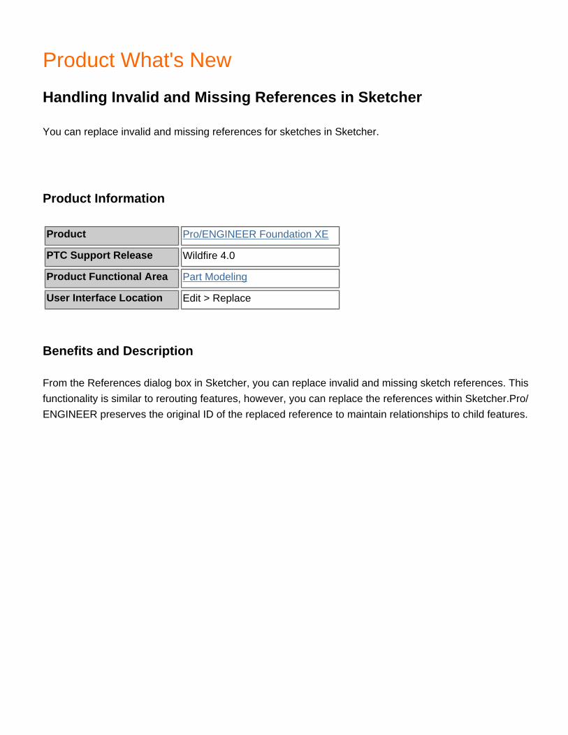
Product What's New
Handling Invalid and Missing References in Sketcher
You can replace invalid and missing references for sketches in Sketcher.
Product Information
Product Pro/ENGINEER Foundation XE
PTC Support Release Wildfire 4.0
Product Functional Area Part Modeling
User Interface Location Edit > Replace
Benefits and Description
From the References dialog box in Sketcher, you can replace invalid and missing sketch references. This functionality is similar to rerouting features, however, you can replace the references within Sketcher.Pro/ENGINEER preserves the original ID of the replaced reference to maintain relationships to child features.

Product What's New
Help Center Improvements
The Pro/ENGINEER Help Center has been improved in content, navigation, and search mechanism.
Product Information
Product Pro/ENGINEER Foundation XE
PTC Support Release Wildfire 4.0
Product Functional Area Fundamentals & Pro/PROGRAM
User Interface Location Click Help > Help Center
Benefits and Description
To improve the quality and accessibility to information, the following improvements have been made to the Pro/ENGINEER Help Center:
● Added support for two levels of search: a simplified search to search through topic titles and an Advanced Search to search through one or more Help areas.
● Added more examples, conceptual information, and tutorials. ● Added and updated overview pages that provide basic introduction to the Help module for most of
the key Help areas.● Enhanced glossaries with new terms and definitions and made them easily accessible. Added
new glossaries for a few Help areas.● Improved navigation within Help with optimized usage of See Also links, inline links, and
bookmarks.● Improved accuracy for context-sensitivity.● Added links to Knowledge Base, Tutorials, and PTC Online Technical Support Tools available on
ptc.com for easy access to useful information.

Product What's New
Heterogeneous Design in Context
Heterogeneous Design in Context helps provide companies with data managed use of multi-cad data in Pro/ENGINEER.
Product Information
Product Pro/ENGINEER Foundation XE
PTC Support Release Wildfire 4.0
Product Functional Area Other Functional Areas
User Interface Location N/A
Benefits and Description
Description
Heterogeneous Design in Context (HDIC) addresses the CAD and data management needs of companies who must use multiple CAD systems in their product development processes. CAD interoperability, multi-CAD data management, and enterprise visualization are key components of HDIC. Wildfire 4.0 in conjunction with PDMLink 9.1 supports heterogeneous design in context between Pro/ENGINEER Wildfire 4.0, Unigraphics NX3/NX4, and CATIA V5 R16.
Wildfire 4.0 data translators for Unigraphics NX3/NX4 and CATIA V5 R10-R16 are Associative Topology Bus (ATB) translators. If ATB source files are modified, Pro/ENGINEER visibly identifies the import geometry as out of date. Users may update the import geometry without losing placement or feature references.
PDMLink 9.1 maps, controls, and maintains the CAD data and interdependency links between Pro/ENGINEER, Unigraphics NX3/NX4, and CATIA V5 R16, tying source and translated CAD Documents to a common WT Part.
Pro/ENGINEER supports import and export of multiple visualization formats including ProductView, JT, and CGR. These formats enable enterprise users to visualize heterogeneous information in the viewer or

CAD system of their choice.
Benefits
Pro/ENGINEER users interacting with Unigraphics and CATIA V5 data sources will find HDIC streamlines the CAD interoperability process. HDIC capabilities eliminate much of the manual conversion process and redefinition of feature and placement references allowing users to work with, rather than on, the data.
PDMLink maintains all the data, ensuring all enterprise users can utilize the design data regardless of their preferred CAD system.
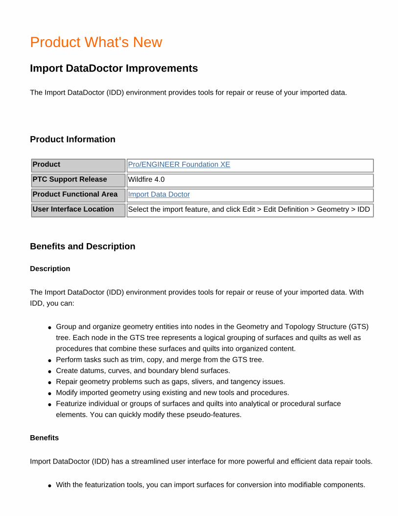
Product What's New
Import DataDoctor Improvements
The Import DataDoctor (IDD) environment provides tools for repair or reuse of your imported data.
Product Information
Product Pro/ENGINEER Foundation XE
PTC Support Release Wildfire 4.0
Product Functional Area Import Data Doctor
User Interface Location Select the import feature, and click Edit > Edit Definition > Geometry > IDD
Benefits and Description
Description
The Import DataDoctor (IDD) environment provides tools for repair or reuse of your imported data. With IDD, you can:
● Group and organize geometry entities into nodes in the Geometry and Topology Structure (GTS) tree. Each node in the GTS tree represents a logical grouping of surfaces and quilts as well as procedures that combine these surfaces and quilts into organized content.
● Perform tasks such as trim, copy, and merge from the GTS tree.● Create datums, curves, and boundary blend surfaces.● Repair geometry problems such as gaps, slivers, and tangency issues.● Modify imported geometry using existing and new tools and procedures.● Featurize individual or groups of surfaces and quilts into analytical or procedural surface
elements. You can quickly modify these pseudo-features.
Benefits
Import DataDoctor (IDD) has a streamlined user interface for more powerful and efficient data repair tools.
● With the featurization tools, you can import surfaces for conversion into modifiable components.

● The GTS Tree displays surface collections in a hierarchy. From the GTS Tree, you can manipulate surfaces and collections of surfaces. You can rename defined groups of surfaces for clarity.
● With these user interface improvements, you can make robust geometry changes without remodeling components. You spend less time remodeling and repairing imported data for downstream use.
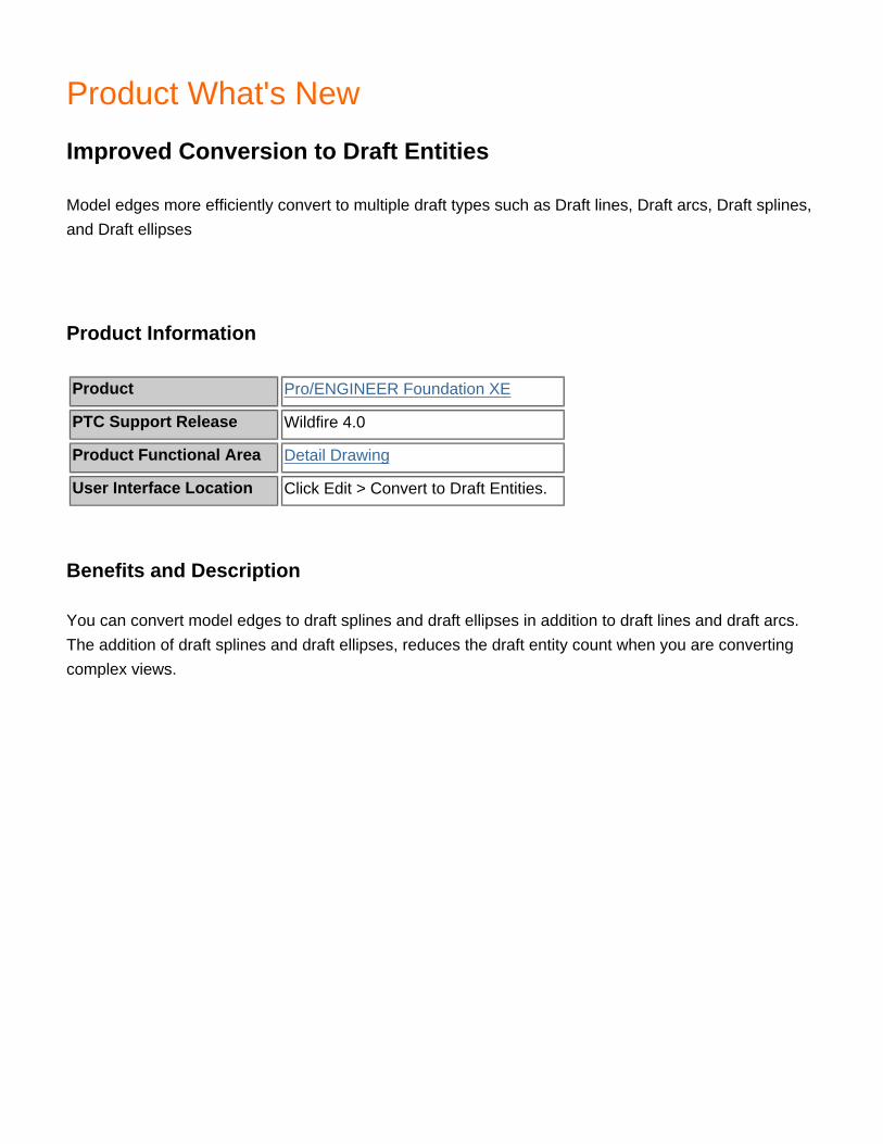
Product What's New
Improved Conversion to Draft Entities
Model edges more efficiently convert to multiple draft types such as Draft lines, Draft arcs, Draft splines, and Draft ellipses
Product Information
Product Pro/ENGINEER Foundation XE
PTC Support Release Wildfire 4.0
Product Functional Area Detail Drawing
User Interface Location Click Edit > Convert to Draft Entities.
Benefits and Description
You can convert model edges to draft splines and draft ellipses in addition to draft lines and draft arcs. The addition of draft splines and draft ellipses, reduces the draft entity count when you are converting complex views.

Product What's New
Improved ModelCHECK Parameter Management
ModelCHECK edits parameters only when necessary.
Product Information
Product Pro/ENGINEER Foundation XE
PTC Support Release Wildfire 4.0
Product Functional Area ModelCHECK
User Interface Location N/A
Benefits and Description
ModelCHECK updates the following ModelCHECK parameters only if the model is modified. This eliminates unnecessary transactions with the PDM system.
● MC_ERRORS● MODEL_CHECK● MC_CONFIG● MC_MODE

Product What's New
Improved Performance when Importing Holes
The performance when importing boards containing a large number of holes is improved.
Product Information
Product Pro/ENGINEER Foundation XE
PTC Support Release Wildfire 4.0
Product Functional Area ECAD
User Interface Location Click File > Open and then select ECAD IDF in the Type box.
Benefits and Description
Performance when importing holes as features is improved by up to 50%. To further improve import performance, you can import holes as a single cut with a non regenerated section or you can filter holes out based on:
● Hole type● Hole type and associated part● Associated part● Diameter

Product What's New
Improved Sharing of User-Defined Wall Sections
You can store user-defined wall sections for reuse on other parts.
Product Information
Product Pro/ENGINEER Foundation XE
PTC Support Release Wildfire 4.0
Product Functional Area Sheetmetal Design and Manufacturing
User Interface LocationFor the Flat Wall click the Shape panel in the dashboard. For the Flange Wall, click the Profile panel in the dashboard.
Benefits and Description
You can store flat wall and flange wall sections to disk from the dashboard. You can then retrieve them from disk using the dashboard. This makes it easier for team member to reuse special walls. The wall sections are stored as *.sec files.

Product What's New
Improved Swept Blend
You can add a normal to plane constraint on a Swept Blend.
Product Information
Product Pro/ENGINEER Foundation XE
PTC Support Release Wildfire 4.0
Product Functional Area Part Modeling
User Interface Location Insert> Swept Blend
Benefits and Description
When creating a Swept Blend, you can make the start or end section normal to the sketching plane.

Product What's New
Improvements to Basic Dimension Types
When text is added to basic dimensions such as a prefix or suffix), the content appears outside of the basic dimension box.
Product Information
Product Pro/ENGINEER Foundation XE
PTC Support Release Wildfire 4.0
Product Functional Area Detail Drawing
User Interface LocationRight-click a dimension and click Properties. Under Display click Basic. Create additional text.
Benefits and Description
For all types of basic dimension presentations, additional text appears outside the basic dimension box.

Product What's New
Improvements to Cross Hatching in Drawings
Cross hatches in drawings have greater flexibility. You can use the same workflow for controlling section attributes for 2D sketches and 2D sections. You can also control the visibility of entire sections, components, or component areas. You can hatch or fill flat surfaces. You can control hidden line removal (HLR) for surface and 2D section crosshatches, and control default visibility of crosshatches for 2D and 3D sections.
Product Information
Product Pro/ENGINEER Foundation XE
PTC Support Release Wildfire 4.0
Product Functional Area Detail Drawing
User Interface Location
Right-click on the crosshatch or fill and select Properties to open the MOD XHATCH menu. Set the configuration option hlr_for_xhatches. Set the drawing options default_show_2d_section_xhatch and default_show_3d_section_xhatch.
Benefits and Description
You can hatch or fill by right-clicking the surface and selecting Hatch or Fill. Then, right-click the crosshatch and select Properties to edit the properties of the crosshatch.
On the MOD XHATCH menu, use the Area command to show or hide areas of component sections. You can also control visibility for components or the entire section. However, control of the hatch definition is only at the component level.
The configuration option hlr_for_xhatches enables hidden line removal (HLR) for crosshatches in drawings. Two new drawing setup options control the default visibility of 2D and 3D sections in drawings: default_show_3d_section_xhatch and default_show_2d_section_xhatch.

Product What's New
Incremental Update and Design Collaboration
You can incrementally update printed circuit board (PCB) outline and component information. By cross-highlighting objects with reference designs between Pro/ENGINEER and InterComm Expert, live MCAD/ECAD collaboration sessions are possible.
Product Information
Product Pro/ENGINEER Foundation XE
PTC Support Release Wildfire 4.0
Product Functional Area ECAD
User Interface Location Click Applications > ECAD Collaboration.
Benefits and Description
Incrementally updating PCBs:
● Improves performance and assembly stability. ● Enhances the ability to preview, highlight, and zoom into changed components. ● Provides tools to investigate proposed changes prior to acceptance or rejection.
When you dynamically collaborate and cross highlight between the ECAD and MCAD domains, design queries and proposals are more efficient.

Product What's New
Intent Objects as Sketcher References
Intent objects are supported as sketcher references.
Product Information
Product Pro/ENGINEER Foundation XE
PTC Support Release Wildfire 4.0
Product Functional Area Part Modeling
User Interface Location N/A
Benefits and Description
You can select composite curves and intent chains as sketcher references. This extends point-on and tangent constraints across multiple entities within the sketch. As a result there are more complex and robust relationships between features. You can also select intent chains and composite curves for Use-Edge and Offset-Edge operations. Intent chain modifications are automatically updated in the sketch.
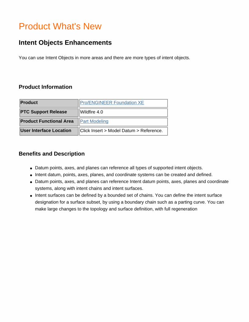
Product What's New
Intent Objects Enhancements
You can use Intent Objects in more areas and there are more types of intent objects.
Product Information
Product Pro/ENGINEER Foundation XE
PTC Support Release Wildfire 4.0
Product Functional Area Part Modeling
User Interface Location Click Insert > Model Datum > Reference.
Benefits and Description
● Datum points, axes, and planes can reference all types of supported intent objects.● Intent datum, points, axes, planes, and coordinate systems can be created and defined.● Datum points, axes, and planes can reference Intent datum points, axes, planes and coordinate
systems, along with intent chains and intent surfaces.● Intent surfaces can be defined by a bounded set of chains. You can define the intent surface
designation for a surface subset, by using a boundary chain such as a parting curve. You can make large changes to the topology and surface definition, with full regeneration

Product What's New
Interface for ProductView Enhancement
The Interface for ProductView now supports the import of ProductView data as exact representation geometry.
Product Information
Product Pro/ENGINEER Foundation XE
PTC Support Release Wildfire 4.0
Product Functional Area 3D Interface
User Interface Location File > Open > ProductView *.ol, *.ed, *.edz (Type drop down)
Benefits and Description
Description
Pro/ENGINEER Wildfire 4.0 now supports import of ProductView exact representation data in addition to existing support for facet representation data. Users can choose which representation to import when opening ProductView files in Pro/ENGINEER.
Benefits
Any CAD specific format published with exact representation data into ProductView format can be opened in Pro/ENGINEER as exact geometry.

Product What's New
Line Style and Color for Sketched Entities
You can assign a line style and color to sketched entities
Product Information
Product Pro/ENGINEER Foundation XE
PTC Support Release Wildfire 4.0
Product Functional Area Part Modeling
User Interface LocationRight-click the entity and select Properties or click View > Display Settings > System Colors > Sketcher.
Benefits and Description
You can assign a line color and style to sketched entities by right-clicking the entity and selecting Properties. These settings remain with the completed sketch. For some entities you can preset line style and color from the System Colors dialog box.
Product What's New
Mapkey Enhancements
Mapkey recording for relations and selection filters is improved.
Product Information
Product Pro/ENGINEER Foundation XE
PTC Support Release Wildfire 4.0
Product Functional Area Fundamentals & Pro/PROGRAM
User Interface Location N/A
Benefits and Description
The configuration option relation_tool_mapkey_behavior improves the use of mapkeys when adding relations. You can set this configuration option to incremental or full_output. When set to incremental:
● As you record the mapkey,the incremental changes made in the Relations dialog box and any new information is stored.
● When you activate the mapkey in another model, the information is added to the existing relations.
● You can use the mapkey to remove text and record the number of characters that were deleted at the cursor position. When executed, the same number of characters from the current cursor position is removed.
You can also use mapkeys to select a specific filter, regardless of the position of the filter in a list. When executed, the filter name stored in the mapkey is used.

Product What's New
Mathcad - Pro/ENGINER Integration Enhancements
In Pro/ENGINEER Wildfire 4.0, new Mathcad compatibility and other enhancements are provided.
Product Information
Product Pro/ENGINEER Foundation XE
PTC Support Release Wildfire 4.0
Product Functional Area Other Functional Areas
User Interface Location
Benefits and Description
N/A

Product What's New
Merge Features Accept Multiple Quilts
You can use the Merge feature to merge more than two quilts
Product Information
Product Pro/ENGINEER Foundation XE
PTC Support Release Wildfire 4.0
Product Functional Area Part Modeling
User Interface Location Click Edit > Merge.
Benefits and Description
You can use the Merge feature to merge more than two quilts if the quilts share the same edge boundary. Select individual adjacent quilts, or select a region. All selected quilts are added to the collector in the order they appear in the Model tree. You must add quilts in the Merge feature sequentially. Diagnostics in the dashboard and in the troubleshooter provide feedback to help you reorder quilts when they are in the wrong order or do not share common edge boundaries.

Product What's New
Modify Model Edges in Drawings
You can alter the display of model edges directly in drawings.
Product Information
Product Pro/ENGINEER Foundation XE
PTC Support Release Wildfire 4.0
Product Functional Area Detail Drawing
User Interface Location Right-click on an edge and select Line Style.
Benefits and Description
There is no need to convert model edges to draft entities before altering their display state in drawings. You can modify the following attributes of model edges directly on the model view:
●
Color
●
Thickness
●
Line style (font)
When modifying a model edge, you can select to alter only the selected edge or all occurrences of that edge in the sheet.

Product What's New
New Interface for JT
PTC introduces a new Interface for JT module for Pro/ENGINEER Wildfire 4.0.
Product Information
Product Pro/ENGINEER Foundation XE
PTC Support Release Wildfire 4.0
Product Functional Area 3D Interface
User Interface Location File > Open > JT *.jt (file type) OR File > Save A Copy > JT *.jt (file type)
Benefits and Description
Description
Pro/ENGINEER Wildfire 4.0 now supports JT visualization format through a new add-on module. Pro/ENGINEER parts and assemblies can be exported to JT format and JT parts and assemblies can be imported into Pro/ENGINEER. Users may choose between facet or exact representations for import or export.
Benefits
Importing and exporting JT format enables Pro/ENGINEER users to share more information with Unigraphics and JT Open users. JT files may be imported into Pro/ENGINEER, and used as Pro/ENGINEER parts or assemblies. Pro/ENGINEER can export to JT format for similar use in Unigraphics.

Product What's New
New Method for Positioning Walls in Sheet Metal Mode
Sheet Metal mode includes an Add to Part Edge option for locating walls.
Product Information
Product Pro/ENGINEER Foundation XE
PTC Support Release Wildfire 4.0
Product Functional Area Sheetmetal Design and Manufacturing
User Interface Location Insert > Sheetmetal Wall > Flat/Flange
Benefits and Description
When you select Add to Part Edge , the bend line of the wall is coincident with the selected attachment edge on the part. This gives you direct control over the position of the bend line regardless of the wall bend angle.

Product What's New
Offset Notes to Reference Points and Axes
You can create an offset note referencing datum points and axes in a drawing. You can create Hole table callouts that are either offset or on-axis, and remain offset during geometry modifications.
Product Information
Product Pro/ENGINEER Foundation XE
PTC Support Release Wildfire 4.0
Product Functional Area Detail Drawing
User Interface Location Click Insert > Note and then set Note Types to Offset. Click Make Note.
Benefits and Description
You can manually place notes to be offset from either draft or model datum points and axes.
Hole table callouts are moved, deleted, or added as changes are made to the model and the hole table is updated. You can place callouts on center or at the upper right.

Product What's New
One-by-One Chain Selection
It is easier to select one-by-one chains.
Product Information
Product Pro/ENGINEER Foundation XE
PTC Support Release Wildfire 4.0
Product Functional Area Fundamentals & Pro/PROGRAM
User Interface Location Graphics window
Benefits and Description
To construct a one-by-one chain, select the first segment , press SHIFT and click an adjacent segment. A preview of the chains you can construct appears with the one-by-one chain at the top of the list. Continue to press SHIFT and click to select the segments to add to the one-by-one chain.

Product What's New
Ordinate Dimensions in 3D Models
You can create ordinate dimension sets as 3D annotations.
Product Information
Product Pro/ENGINEER Foundation XE
PTC Support Release Wildfire 4.0
Product Functional Area Other Functional Areas
User Interface Location
Click Insert > Annotations > Annotation Feature. In the Add Annotation dialog box select Ord Baseline, Ord Driven Dimension, or Ord Reference Dimension. To create Ordinate driven and reference dimensions as general model annotations click Insert > Annotations > Ordinate.
Benefits and Description
You can create and organize ordinate baselines and dimension sets like other 3D annotations. Formats such as ANSI, ISO, and JIS are available, and baselines are easily redefined, unlike traditional 2D ordinate baselines.
Product What's New
Parameter and Relations User Interface in Mechanism Design.
The parameter and relations user interfaces are now in Mechanism Design.
Product Information
Product Pro/ENGINEER Foundation XE
PTC Support Release Wildfire 4.0
Product Functional Area Simulation - Mechanism Design & Dynamics
User Interface Location Click Tools > Parameters.
Benefits and Description
You can now use the parameter and relations dialog boxes directly within Mechanism Design. This significantly improves the Mechanism workflow. You can easily use parameters and relations while assigning forces or motors, for example, without having to return to standard mode.

Product What's New
Pattern Enhancements
The Pattern tool is more consistent with other dashboard tools.
Product Information
Product Pro/ENGINEER Foundation XE
PTC Support Release Wildfire 4.0
Product Functional Area Part Modeling
User Interface Location Click Edit > Pattern.
Benefits and Description
Fill patterns use the most recently used (MRU) filters in the following dashboard panels:
● Spacing● Boundary width● Rotation angle● Radial spacing
You can define dimension patterns using relations with the new relations user interface. From the relations toolbar you can click an icon for information on sample relations and symbols you can use to generate a pattern relation.

Product What's New
PDF Enhancements
Several improvements to the Interface for PDF are introduced including support for generation of 3D PDF content.
Product Information
Product Pro/ENGINEER Foundation XE
PTC Support Release Wildfire 4.0
Product Functional Area 3D Interface
User Interface Location File > Save As > *.pdf or *.u3d (file types)
Benefits and Description
Description
Pro/ENGINEER Wildfire 4.0 integrates with Adobe Acrobat 7.0. You can export Pro/ENGINEER parts and assemblies in the following ways:
● Export a 3D model as a U3D model embedded in a 3D PDF page● Export a 3D model as 2D raster image(s) on a PDF page● Export a 3D model as a U3D model
You can select the sheets of a drawing for export to a PDF file.
Benefits
You can export 3D PDFs and leverage U3D files for their specific needs directly from Pro/ENGINEER. Pro/TOOLKIT and Distributed Pro/BATCH also support export of 3D PDF and U3D models for user-developed, custom applications and business automation requirements, respectively.

Product What's New
Redefinition Options for Features with External References
New options are available while redefining features disconnected from their external references.
Product Information
Product Pro/ENGINEER Foundation XE
PTC Support Release Wildfire 4.0
Product Functional Area Part Modeling
User Interface Location N/A
Benefits and Description
If you are using the model in different assembly you can
· See internal backup references (created through Reference Control) as feature sub nodes.
· Externalize the sub notes to be regular Copy Geometry features (Advanced Assembly Design only).
If you are using another occurrence of the Model in the same assembly you can:
· Redefine the feature in the context it was created.
· Update the context of the feature to the context where redefinition began.
Product What's New
Reference Handle Visibility
When placing features that require reference handles, such as Holes or Datum Axes, the offset reference handles are different than the handles you use for resizing and reorienting.
Product Information
Product Pro/ENGINEER Foundation XE
PTC Support Release Wildfire 4.0
Product Functional Area Part Modeling
User Interface Location N/A
Benefits and Description
You can now distinguish reference handles from the handles you use to resize and reorient. This makes it easier to select the appropriate references.
Product What's New
Referencing by Intent Name
You can create intent objects using a query that searches by intent name.
Product Information
Product Pro/ENGINEER Foundation XE
PTC Support Release Wildfire 4.0
Product Functional Area Part Modeling
User Interface Location Click Insert > Model Datum > Reference.
Benefits and Description
With a new type of referencing, you can create a feature by searching for an intent name. Intent names are defined within intent objects and are used to define the intent object and how the intent object is referenced by other features.
The intent-name property of an intent object must be unique within a model. To place the same User-Defined feature (UDF) several times in the same model but at different locations, the intent name property has: two parts, For example if the intent name is boss_location:in_* the string boss_location is used for finding all intent objects suitable as a reference, and * is a wild card that is used to select a specific instance and makes the intent name property unique.
To enable a referencing system using intent names, datum reference features can store queries for intent objects. The queries search all datum reference features containing the appropriate type of reference for the appropriate value of the intent-name property. After validating the query, you can store the query in the reference feature. You can then place all objects based off these reference features into a UDF or copy and paste them into other objects. When placed into other objects, the references are reevaluated and regenerated.
After creating a UDF, you are not prompted for any reference containing a query. It is evaluated on placement. Placement is automatic when one match is found or you are prompted for placement if multiple matches are found.

Product What's New
Remove Feature
The new Remove Feature allows user to remove surface geometry from models for downstream uses like structural analysis or casting creation.
Product Information
Product Pro/ENGINEER Foundation XE
PTC Support Release Wildfire 4.0
Product Functional Area Part Modeling
User Interface Location Edit > Remove
Benefits and Description
Description
The Remove feature is a new Object-Action only tool. When the surface geometry allows, it removes user-selected surfaces from a solid or surface quilt and re-intersects adjacent surfaces to fill the resulting gap appropriately. Remove can replace import surfaces and parametric feature surfaces. A Remove solid feature is available in the model tree so geometry removal can be rolled back with suppress, delete, or insert operations.
Benefits
Remove surface is valuable for removing static geometry such as rounds from import features so these surfaces may be reapplied as parametric Pro/ENGINEER features. Users may also find the remove surface tool useful for filling in holes and other machined features to quickly make cast parts or simplification prior to structureal analyses.

Product What's New
Reorient Driven Dimension Annotations
You can reorient driven dimensions that have been created using two points, without redefining.
Product Information
Product Pro/ENGINEER Foundation XE
PTC Support Release Wildfire 4.0
Product Functional Area Detail Drawing
User Interface Location Right-click the dimension and select Properties. Click Orient.
Benefits and Description
You do not have to recreate a driven dimension if a change in orientation is needed. In the Dimension Properties dialog box, click Orient to go to the DIM ORIENT menu. Then select a horizontal, vertical, slanted, parallel, or normal orientation.

Product What's New
Replace Unrelated Components
You can replace a component with an unrelated part or subassembly. Pro/ENGINEER provides the tools to map the references required from both objects to ensure that there is no feature failure due to missing references.
Product Information
Product Pro/ENGINEER Foundation XE
PTC Support Release Wildfire 4.0
Product Functional Area Assembly
User Interface Location Click Edit > Replace.
Benefits and Description
You can replace a part or assembly component at any assembly level and the target component and all its children are automatically replaced. From the Replace dialog box, you can map references from one object to the other. A table walks you through each reference tag by highlighting and color-coding the target and source references. Advanced and more granular reference definitions are also available.
Enhancements include:
● A method to map the assembly references between a model that exists in an assembly and the model that is to replace it.
● A prompt for you to confirm that the assembly references will be mapped correctly before the model is replaced.
● The option to manually change the mapped references, if the references were not mapped correctly.
● Failure resolution procedures if the reference mapping method fails.● Mapping table storage so that you can automatically replace multiple occurrences of the same
model.
You can automatically find pairs of references between the outgoing component and the replacement

component. There are several pairing rules:
● Same Name —Automatically pairs objects with the same name and type. ● Component Interfaces—Searches for the interfaces with the same names and then examines
each definition. If the same reference types are used in each interface then these can be mapped automatically.
● Same History —Searches the replacement model for any external references to the original model. If found, these references are automatically paired.
● Same Parameters—Automatically pairs parameters with the same name and type.
After auto-tagging, auto-selection, or manual selection, a pairing table is created. You can store the pairing table and then use it for replacing the original component or for replacing the same two components in some other assembly. Your storage method may be the current assembly or you may create a new interchange assembly. Both methods have advantages and disadvantages.
Storing a pairing table as a separate interchange assembly:
●
Advantage: Easy to find all interchange assemblies where this component is located.●
Advantage: Easy to offer all possible candidates for replacement.●
Disadvantage: Modifies the models (unwanted with library parts)
Storing a pairing table in the context of the current assembly:
● Advantage: Does not modify the models used for replacement.● Disadvantage: During subsequent replacements on other assemblies, you need to search and
find the appropriate assemblies that define tags for outgoing and incoming components. This may be time consuming.

Product What's New
Restored Features Performance
It takes less time to restore the features in a model after canceling a feature redefinition.
Product Information
Product Pro/ENGINEER Foundation XE
PTC Support Release Wildfire 4.0
Product Functional Area Part Modeling
User Interface Location N/A
Benefits and Description
When you cancel a feature redefinition before making modifications, it takes less time to restore the features in the model. Regeneration messages no longer appear.

Product What's New
Restricted Parameter Enhancements
There are enhancements to restricted parameter definitions.
Product Information
Product Pro/ENGINEER Foundation XE
PTC Support Release Wildfire 4.0
Product Functional Area Fundamentals & Pro/PROGRAM
User Interface Location Click Tools > Parameters
Benefits and Description
When defining a restricted parameter you can:
●
Accept the default for the parameter name and value.●
Select a parameter from the list or type characters to filter the list.●
Press ENTER to select the parameter and automatically position the cursor in the Value box.●
Select a restricted parameter value from the list or type the name of value in the Name box.●
Define restricted parameter names but leave the values of these restricted parameters open for definition.
●
Define conditional ranges of parameters that are defined by specific values from another parameter. Using a table of restrictions a lead parameter, the set label, is defined. Defining one parameter automatically adds all parameters in the table and applies their definitions and restrictions. If the set label changes, then you can apply new restrictions for the effected parameters.

Product What's New
Retain Last Used Annotation Orientation
The definition of planar space, text direction, and viewing angle of a 3D annotation are captured in a single definition of the active annotation orientation. This definition establishes the orientation for any newly created annotations.
Product Information
Product Pro/ENGINEER Foundation XE
PTC Support Release Wildfire 4.0
Product Functional Area Other Functional Areas
User Interface Location N/A
Benefits and Description
You do not have to manually set the annotation plane and text orientation for each 3D annotation. After you set an active annotation orientation, new annotations use this same orientation, until you define a new one.

Product What's New
Retrieving Family Table Instances is Faster
Retrieving assemblies that contain Family Table Instances is now faster. This is due to improvements in Instance accelerator files, and in the retrieval of nested Family Table Instances and Instance dependencies.
Product Information
Product Pro/ENGINEER Foundation XE
PTC Support Release Wildfire 4.0
Product Functional Area Assembly
User Interface Location N/A
Benefits and Description
Instance accelerator files are used even though they may be partially out of date. This significantly reduces the need for regeneration while retrieving Family Table Instances, even though changes have been made to the Generic.
Retrieving nested family tables instances requires retrieval and regeneration of the top level Generic only.
Less regeneration reduces assembly retrieval time.
Use the following options to control instance dependencies:
· Full retrieval —All Generics and all their dependencies are retrieved and fully regenerated. This was the default prior to Pro/ENGINEER Wildfire 4.0.
· Required dependencies only —Dependency retrieval is limited to Generic and Instance dependencies that are required for full regeneration of the retrieved Instance. This is the new default..
· Instance dependencies only—Dependency retrieval is limited to Instance dependency. Missing dependencies result in frozen references or additional model regeneration.


Product What's New
Saving Models in a Clipped State
You can save a model in a clipped state.
Product Information
Product Pro/ENGINEER Foundation XE
PTC Support Release Wildfire 4.0
Product Functional Area Part Modeling
User Interface Location N/A
Benefits and Description
Set the configuration option save_clipped_view to to yes, to save the clipping state of a model, when you save the model. When retrieved, the model appears with the clipped view.

Product What's New
Selecting Silhouette Edges of Non-Analytic Surfaces
In Drawing mode you can reference the silhouette edges that are created by non analytic surfaces.
Product Information
Product Pro/ENGINEER Foundation XE
PTC Support Release Wildfire 4.0
Product Functional Area Detail Drawing
User Interface Location When dimensioning, creating snap lines, and so on.
Benefits and Description
You can select silhouette edges of both analytic and non analytic surfaces for referencing.
Valid analytic surfaces include:
●
Cylinder●
Cone●
Torus (when axis is perpendicular or parallel to the drawing)●
Revolved surface (when revolution axis is perpendicular or parallel to the drawing)
Now, silhouette edges from all other surfaces are valid for referencing and dimensioning.

Product What's New
Set Datum Tag Improvements in Drawings
You can attach draft set datum tags to model arcs, model circles, draft arcs, and draft circles.
Product Information
Product Pro/ENGINEER Foundation XE
PTC Support Release Wildfire 4.0
Product Functional Area Detail Drawing
User Interface LocationWhen editing the properties of a draft datum axis tag, click Set (display with a triangle).
Benefits and Description
You can create:
● Set datum tags on the axes of model arcs, draft arcs, model circles, and draft circles.
● Triangular-style datum tags on model edges or draft entities.
When attached to small-radius edges or entities, there is no gap between the datum triangle and the entity.

Product What's New
Setting for Displayed Significant Digits
The detail setup option, dim_trail_zero_max_places, sets the number of decimal places when trailing zeroes are used to reach the number of decimal places set by configuration option, default_dec_places.
Product Information
Product Pro/ENGINEER Foundation XE
PTC Support Release Wildfire 4.0
Product Functional Area Detail Drawing
User Interface LocationClick File > Properties > Drawing Options, and set dim_trail_zero_max_places.
Benefits and Description
Specify a value for dim_trail_zero_max_places that is less than the specified number of decimal places to control the number of trailing zeros for dimensions and tolerances. This option:
●
Does not affect decimal places if the value specified for the lead_trail_zeros prevents the display of trailing zeros.
●
Affects the display of all dimensions in a drawing. You cannot individually control the number of decimal places for dimensions with trailing zeros.
●
Does not affect angular dimensions displayed in the degree, minute, and second format.
For example if dim_trail_zero_max_places is set to 2 and the default decimal places is set to 3:
●
A value of 0.5 appears as 0.50●
A value of 0.3278 appears as 0.328

Product What's New
Sheet Metal Thickness is a Part Parameter
The thickness of sheet metal parts is controlled by a new part-level parameter.
Product Information
Product Pro/ENGINEER Foundation XE
PTC Support Release Wildfire 4.0
Product Functional Area Sheetmetal Design and Manufacturing
User Interface Location Tools > Parameter
Benefits and Description
New sheet metal parts contain the part-level parameter SMT_THICKNESS, which drives the thickness of all sheet metal walls.
You can still access the thickness value by editing the first wall of the part, but editing the first wall now updates the parameter value.

Product What's New
Shell Geometry Enhancements
You can create more robust geometry using the Shell feature.
Product Information
Product Pro/ENGINEER Foundation XE
PTC Support Release Wildfire 4.0
Product Functional Area Part Modeling
User Interface Location Click Insert > Shell.
Benefits and Description
From the Shell feature you can:
● Remove individual surfaces that are tangent to neighboring surfaces. ● Specify a unique thickness value to an individual surface even if the surface is tangent to its
neighbors. ● Close off a shell if a portion of the model is removed. You can leave the void or close it off from
the Options panel.

Product What's New
Shortcut to Layer Commands
The following layer commands are removed from the Visibility menu (View > Visibility) and relocated under Layer in the Layer Tree: Isolate, Hidden Line, Copy Status From, and Drawing Dependent.
Product Information
Product Pro/ENGINEER Foundation XE
PTC Support Release Wildfire 4.0
Product Functional Area Detail Drawing
User Interface Location Right-click on a layer in the Layer Tree.
Benefits and Description
Using a floating layer tree is more efficient now that all layer commands are available.

Product What's New
Show Full Part Names in the Graphics Window
When a part is activated in an assembly, you can see the entire part name in the Graphics window.
Product Information
Product Pro/ENGINEER Foundation XE
PTC Support Release Wildfire 4.0
Product Functional Area Fundamentals & Pro/PROGRAM
User Interface Location Graphics window
Benefits and Description
● The character limit is increased to 31 characters after the colon..● In 3D, the position of the text is left justified, increasing the allowable amount of text. ● Window tags are slightly smaller than datum tags.● Window tags have the same color as the hidden line color.

Product What's New
Shrinkwrap Feature Enhancements
Shrinkwrap features regenerate faster and remain associated with the Simplified Representation or Family Table instance in which they were created or redefined. Surface selection is simplified.
Product Information
Product Pro/ENGINEER Foundation XE
PTC Support Release Wildfire 4.0
Product Functional Area Assembly
User Interface Location Right-click on the Shrinkwrap dashboard and select Exclude.
Benefits and Description
· Shrinkwrap feature regeneration is more robust, reducing design time.
· By default, the Shrinkwrap feature stays associated with the Simplified Representation or Family Table instance in which it was redefined or created.
· You can edit the definition of a Shrinkwrap feature to associate it with a different Simplified Representation or Family Table Instance.
· You can easily clear individual surfaces from the definition.

Product What's New
Simplified Representation Preview
You can preview a simplified representation before you open it.
Product Information
Product Pro/ENGINEER Foundation XE
PTC Support Release Wildfire 4.0
Product Functional Area Assembly
User Interface LocationClick File > Open and select an assembly. Click Open Rep. In the Open Rep dialog box click >> (Show Preview).
Benefits and Description
Previewing a simplified representation is fully supported.
You can:
· Preview simplification definitions in the Open Rep dialog box.
· Preview external simplified representations.

Product What's New
Simplified Representation Support in Family Table Instances.
You can create Simplified Representations of Assembly Family Tables instances in the same way that you create a simplified representation of an assembly. The simplified representation can now be created in the actual instance.
Product Information
Product Pro/ENGINEER Foundation XE
PTC Support Release Wildfire 4.0
Product Functional Area Assembly
User Interface Location N/A
Benefits and Description
All Simplified Representation definitions are shared within the Family Table. You can use a Simplified Representation definition in another instance or generic, regardless of whether it was created in an instance or a generic. This gives you more flexibility and makes simplified representations easier to reuse.

Product What's New
Sketcher Diagnostics
Sketcher diagnostic tools are added to help you understand issues in your sketch real-time.
Product Information
Product Pro/ENGINEER Foundation XE
PTC Support Release Wildfire 4.0
Product Functional Area Part Modeling
User Interface Location Sketch > Diagnostics
Benefits and Description
Four diagnostic tools are available:
● Shade Closed Loops—Shades entities that form a closed loop by filling the area enclosed by the entity, with a predefined color.
● Highlight Open Ends—Highlights the end points of entities that are not common to more than one entity
● Overlapping Geometry—Highlights overlapping entities.
● Feature Requirements—Analyzes the sketch to determine if it meets the requirements for the feature in which it is embedded. The Feature Requirements diagnostic tool is available only with 3D Sketcher and not with 2D Sketcher.

Product What's New
Snapping a Room to the Model
Any aspect of a room can be snapped to the model.
Product Information
Product Pro/ENGINEER Foundation XE
PTC Support Release Wildfire 4.0
Product Functional Area Rendering
User Interface Location View > Model Display > Room
Benefits and Description
You can snap the walls, floor, and ceiling of the room to the closest geometric element of the model.

Product What's New
Spring Objects as Pro/ENGINEER Features
Spring objects are now Pro/ENGINEER features.
Product Information
Product Pro/ENGINEER Foundation XE
PTC Support Release Wildfire 4.0
Product Functional Area Simulation - Mechanism Design & Dynamics
User Interface Location Click Insert > Spring.
Benefits and Description
Springs in Mechanism Design are now Pro/ENGINEER features. They can be used in any feature operations, such as suppress or resume, Family Tables, relations, and BMX analyses.

Product What's New
Starting Pro/TOOLKIT Applications from Distributed Pro/BATCH
Distributed Pro/BATCH has been extended to allow batch execution of custom Pro/TOOKLIT applications.
Product Information
Product Pro/ENGINEER Foundation XE
PTC Support Release Wildfire 4.0
Product Functional Area Other Functional Areas
User Interface Location N/A
Benefits and Description
Description
With Distributed Pro/BATCH, you can now create and run powerful, customized batch tasks based on your own Pro/TOOLKIT applications. A customizable Task Type Definition (TTD) template is provided. This template expands the usability of Pro/BATCH, which uses over 70 predefined tasks.
Benefits
Batch automation of your enterprise tasks is now only limited by your imagination. You can take tedious, repetitive tasks off-line, freeing designers to do value-added design work.
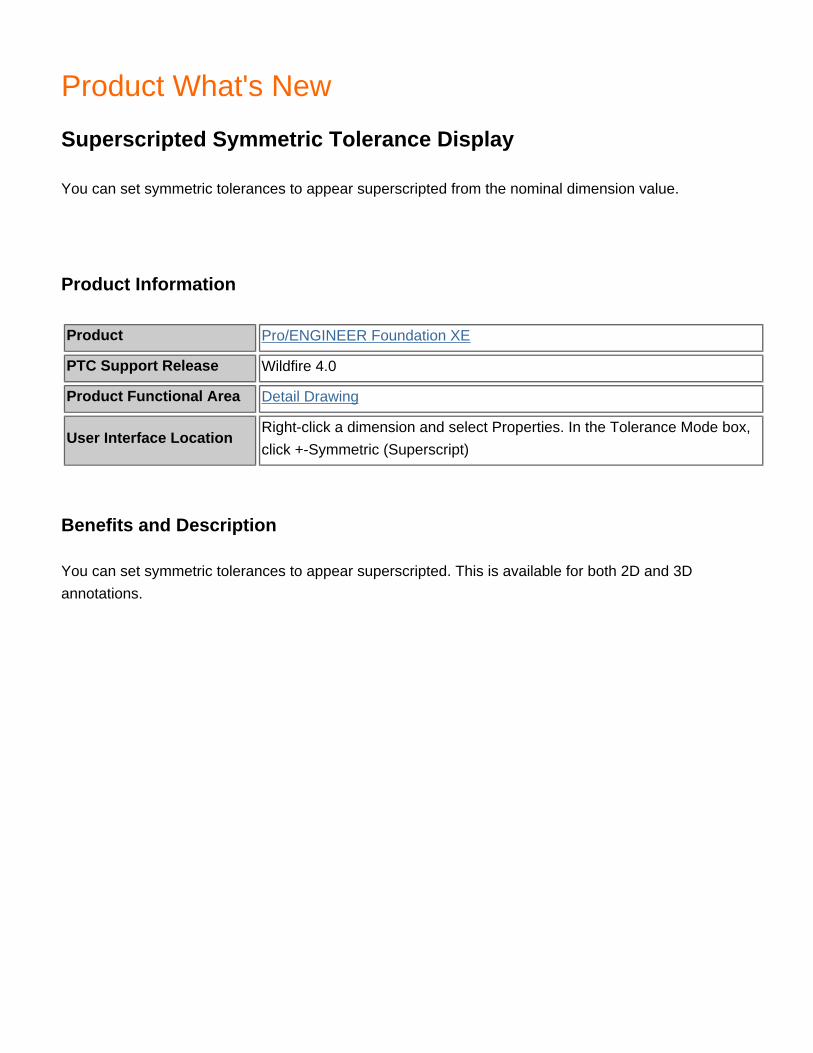
Product What's New
Superscripted Symmetric Tolerance Display
You can set symmetric tolerances to appear superscripted from the nominal dimension value.
Product Information
Product Pro/ENGINEER Foundation XE
PTC Support Release Wildfire 4.0
Product Functional Area Detail Drawing
User Interface LocationRight-click a dimension and select Properties. In the Tolerance Mode box, click +-Symmetric (Superscript)
Benefits and Description
You can set symmetric tolerances to appear superscripted. This is available for both 2D and 3D annotations.

Product What's New
Surface Profile Geometric Tolerance Comply with Standard
You can create a surface profile geometric tolerance (GTOL) in accordance with the Y14.41 standard. This enables an unequal disposition of the tolerance zone.
Product Information
Product Pro/ENGINEER Foundation XE
PTC Support Release Wildfire 4.0
Product Functional Area Other Functional Areas
User Interface LocationIn a model or drawing, click Insert > Geometric Tolerance and select the Profile type. Click the Symbols tab and set the style to ASME Y14.41.
Benefits and Description
You can create a GTOL with unequal disposition. When you create a GTOL with unequal or unilateral disposition, a circled U symbol appears in the GTOL control frame, in compliance with ASME Y14.41 standards.

Product What's New
Surface Reference for Driven Dimensions
When creating driven 3D dimensions, you can use both surface references and traditional edge references.
Product Information
Product Pro/ENGINEER Foundation XE
PTC Support Release Wildfire 4.0
Product Functional Area Other Functional Areas
User Interface LocationWhen creating driven dimension annotations, click On Surface from the Attach Type menu.
Benefits and Description
Using surface references increases the robustness of driven dimensions, since edge references can change or be deleted when other features are added or modified.

Product What's New
Toggle Display of Annotations
You can quickly turn on and off the display of all 3D annotations.
Product Information
Product Pro/ENGINEER Foundation XE
PTC Support Release Wildfire 4.0
Product Functional Area Other Functional Areas
User Interface LocationClick View > Display Settings > Datum Display, and click 3D Annotations. A button is also added to the default Datum Display toolbar.
Benefits and Description
There is a new option to toggle the display of all 3D annotations. This replaces the previous Environment option to hide or show 3D Notes.
As you add more annotation content to the 3D model, the Graphics window may appear cluttered. When you don’t need this content, such as when using Sketcher, you can turn it off for a cleaner display.

Product What's New
Transparent Display Style
There is a new transparent display style for components.
Product Information
Product Pro/ENGINEER Foundation XE
PTC Support Release Wildfire 4.0
Product Functional Area Assembly
User Interface Location Click View > Display Style > Transparent.
Benefits and Description
You can easily make components transparent in assemblies. This is critical when you need to view the inner components. From the View Manager, you can save the transparent style into a style state as you can save other display styles. To easily toggle different styles, simplified representations, explode states, and orientations, store graphical changes into combination states.
Set the configuration option style_state_transparency to change the default transparency for components. The values for this option range between 0 and 100. When set to 100, the component is completely transparent..

Product What's New
UDF Enhancements
Previewing User-Defined Features (UDFs) is enhanced. Hidden status is maintained in the target object.
Product Information
Product Pro/ENGINEER Foundation XE
PTC Support Release Wildfire 4.0
Product Functional Area Fundamentals & Pro/PROGRAM
User Interface Location N/A
Benefits and Description
When you place a UDF containing features with external references to datum planes, you may need to define the side. A new Preview dialog box opens so you can choose the datum plane and flip the direction. You can also use a Preview button to see the new location. If you like, you can choose to accept all defaults and then make changes later if you are not satisfied with the placement.
Hidden items in the UDF also have hidden status when placed into the target object.
You can automatically hide Annotation Elements in UDFs when copying and pasting a UD,F by setting the configuration option autohide_copied_group_af. For example, f you place a UDF and then copy it three times, the Annotation Elements for the last three UDFs are automatically hidden. You can also automatically unhide the content of the next UDF if the first UDF is deleted. For example if you delete the first UDF, the Annotation Elements in the second UDF are automatically unhidden.

Product What's New
Undoing and Redoing View Orientation States in Sketcher
Undo and Redo commands are available for view orientation states in Sketcher.
Product Information
Product Pro/ENGINEER Foundation XE
PTC Support Release Wildfire 4.0
Product Functional Area Part Modeling
User Interface Location Click Edit > Undo or Edit > Redo
Benefits and Description
Set the configuration option sketcher_undo_reorient_view to Yes to save the view state as part of the undo/redo stack in sketcher mode. You can click Undo or Redo to quickly view recent changes, including changes to the view.

Product What's New
Updates to Active Layers
Objects maintain their active layer status as you navigate between open windows. When a layer is activated, layers with the same name are activated in any sub-models.
Product Information
Product Pro/ENGINEER Foundation XE
PTC Support Release Wildfire 4.0
Product Functional Area Detail Drawing
User Interface Location Click View > Layers.
Benefits and Description
You must manually activate a layer for any object opened in a new window. The layer you activate is recalled as you navigate between open windows. If that top-level model has any sub models containing layers with the same name, those layers are also activated.
Adding draft content to an active drawing layer adds the appropriate model content to the layer with the same, if one exists in the model of the drawing.
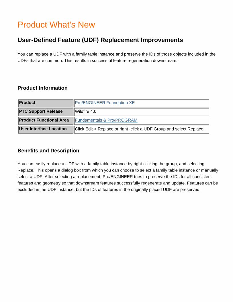
Product What's New
User-Defined Feature (UDF) Replacement Improvements
You can replace a UDF with a family table instance and preserve the IDs of those objects included in the UDFs that are common. This results in successful feature regeneration downstream.
Product Information
Product Pro/ENGINEER Foundation XE
PTC Support Release Wildfire 4.0
Product Functional Area Fundamentals & Pro/PROGRAM
User Interface Location Click Edit > Replace or right -click a UDF Group and select Replace.
Benefits and Description
You can easily replace a UDF with a family table instance by right-clicking the group, and selecting Replace. This opens a dialog box from which you can choose to select a family table instance or manually select a UDF. After selecting a replacement, Pro/ENGINEER tries to preserve the IDs for all consistent features and geometry so that downstream features successfully regenerate and update. Features can be excluded in the UDF instance, but the IDs of features in the originally placed UDF are preserved.

Product What's New
Visual Basic Application Programming Interface (API)
Pro/ENGINEER Wildfire 4.0 introduces a new programming interface for Visual Basic.
Product Information
Product Pro/ENGINEER Foundation XE
PTC Support Release Wildfire 4.0
Product Functional Area Other Functional Areas
User Interface Location N/A
Benefits and Description
Description
A new Parametric Foundation Classes (PFC) based Visual Basic API is available in Wildfire 4.0. Users versed in Visual Basic programming can use this new API to automate and customize Pro/ENGINEER from Visual Basic.NET applications and Visual Basic macros in applications like Microsoft Word, Excel or Access.
The Visual Basic API:
● Contains the same capabilities as asynchronous J-Link (core Pro/ENGINEER part, assembly, and drawing manipulation; Windchill server access; data exchange; Pro/ENGINEER user interface customization and applications triggered by events occurring in the Pro/ENGINEER session)
● Is compatible with Visual Basic .NET 2005 and Visual Basic for Applications● Can be used to transfer data between drawings and OLE objects embedded in Pro/ENGINEEER
drawings, such as Excel spreadsheets● Requires no license beyond the license to run Pro/ENGINEER
Benefits
Users already familiar with Visual Basic will find this API easier to use than less familiar APIs. Users may

apply this API to transfer information between Pro/ENGINEER and other Windows applications with Visual Basic APIs.
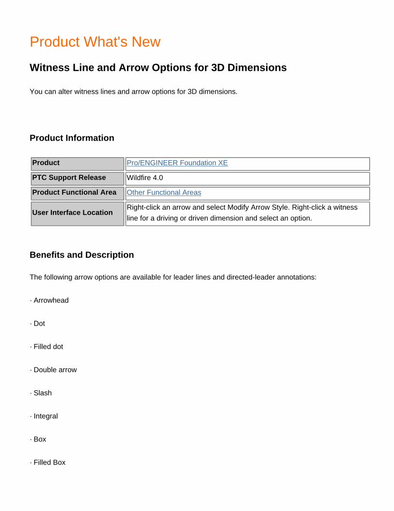
Product What's New
Witness Line and Arrow Options for 3D Dimensions
You can alter witness lines and arrow options for 3D dimensions.
Product Information
Product Pro/ENGINEER Foundation XE
PTC Support Release Wildfire 4.0
Product Functional Area Other Functional Areas
User Interface LocationRight-click an arrow and select Modify Arrow Style. Right-click a witness line for a driving or driven dimension and select an option.
Benefits and Description
The following arrow options are available for leader lines and directed-leader annotations:
· Arrowhead
· Dot
· Filled dot
· Double arrow
· Slash
· Integral
· Box
· Filled Box

· None
· Target (new)
You can alter witness lines for driving and driven 3D dimensions by:
· Skewing the dimension.
· Inserting or removing jogs.
· Inserting or removing breaks.
· Erasing or showing witness lines.
· Clipping witness lines.

Product What's New
Style Curve Tuning
The Style curve creation and editing tools are enhanced
Product Information
Product Pro/ENGINEER Interactive Surface Design
PTC Support Release Wildfire 4.0
Product Functional Area Surfacing - ISDX
User Interface Location Click Show Original on the Curve Edit dashboard
Benefits and Description
You can extend a curve-on-surface (COS) to the boundaries of a surface. Use the Extend option on the dashboard to force COS sub-features (Drop and Offset) to run to the boundary of their parent surface. For a generic COS, a shortcut menu provides the same functionality. COS sub-features are enhanced when required for trimming a surface.
During editing, a ghosted display of the original curve appears so you can see how far you move the curve. This ghosted display is removed when you complete the edit operation. You can hide the ghost if it is not required.

Product What's New
Style in Assembly
Style is available for assembly-level features
Product Information
Product Pro/ENGINEER Interactive Surface Design
PTC Support Release Wildfire 4.0
Product Functional Area Surfacing - ISDX
User Interface Location Insert > Style
Benefits and Description
You can now create assembly-level Style features. Previously, Style was available for part-level features only.
As a result, part-level trace-sketches are now visible when viewing an assembly.

Product What's New
Style Tree
The Style feature has a sub-feature tree, listing each entity in the feature
Product Information
Product Pro/ENGINEER Interactive Surface Design
PTC Support Release Wildfire 4.0
Product Functional Area Surfacing - ISDX
User Interface Location Under the Pro/ENGINEEER model tree
Benefits and Description
The Style tree gives you a new way to interact with and interrogate a Style feature. The tree is embedded under the Pro/ENGINEER model tree. Each entity in the Style feature is listed so that you can select, rename, hide or unhide. Information on entities, such as parent and child information, is also available

Product What's New
Surface Edit
You can use the Style feature to directly edit a surface by pulling on a control mesh
Product Information
Product Pro/ENGINEER Interactive Surface Design
PTC Support Release Wildfire 4.0
Product Functional Area Surfacing - ISDX
User Interface Location On the Style toolbar, or click Styling > Surface Edit
Benefits and Description
You can use the Surface Edit tool inside the Style feature to directly pull and push on a surface, using a control mesh. You can edit a surface multiple times at different mesh resolutions and all edits are managed during model regeneration. When the underlying surface changes, then the surface edit is reapplied during regeneration.
This is important when you need a subtle surface change to smooth out a small ripple or add more loft to a surface. This tool is also useful for general surface modeling, eliminating the need to construct internal curves.
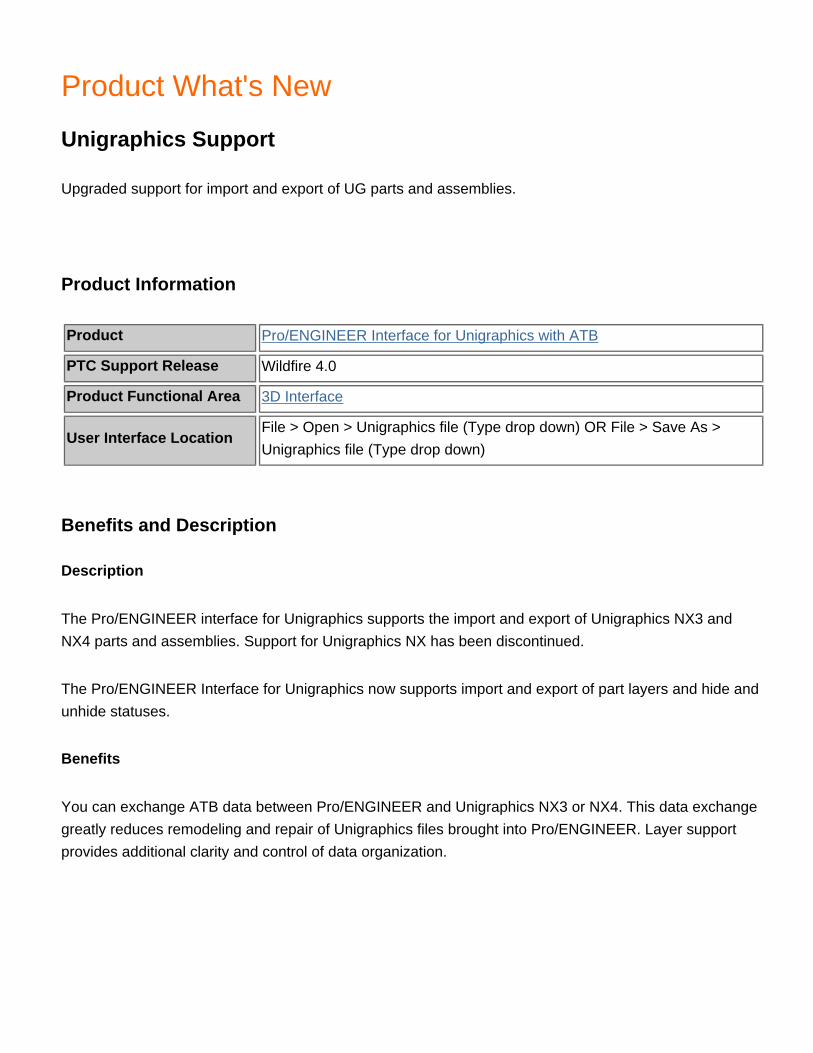
Product What's New
Unigraphics Support
Upgraded support for import and export of UG parts and assemblies.
Product Information
Product Pro/ENGINEER Interface for Unigraphics with ATB
PTC Support Release Wildfire 4.0
Product Functional Area 3D Interface
User Interface LocationFile > Open > Unigraphics file (Type drop down) OR File > Save As > Unigraphics file (Type drop down)
Benefits and Description
Description
The Pro/ENGINEER interface for Unigraphics supports the import and export of Unigraphics NX3 and NX4 parts and assemblies. Support for Unigraphics NX has been discontinued.
The Pro/ENGINEER Interface for Unigraphics now supports import and export of part layers and hide and unhide statuses.
Benefits
You can exchange ATB data between Pro/ENGINEER and Unigraphics NX3 or NX4. This data exchange greatly reduces remodeling and repair of Unigraphics files brought into Pro/ENGINEER. Layer support provides additional clarity and control of data organization.

Product What's New
Assembly Connectivity Manager
Interfaces are created through a common dialog box.
Product Information
Product Pro/ENGINEER Mechanica
PTC Support Release Wildfire 4.0
Product Functional Area Simulation - Structural & Thermal
User Interface Location Click Insert > Connection > Interface
Benefits and Description
All interfaces are now created through a common user interface. With the Interface dialog box, you can assign Bonded, Free or Contact interfaces between selected components in structural analyses, and Bonded, Adiabatic, or Thermal Resistance interfaces in Thermal assemblies.

Product What's New
AutoGEM Max Element Size for Mesh Control
You can control the maximum size of elements for mesh created by the AutoGEM mesh generator in particular areas of a model.
Product Information
Product Pro/ENGINEER Mechanica
PTC Support Release Wildfire 4.0
Product Functional Area Simulation - Structural & Thermal
User Interface Location Click AutoGEM > Control.
Benefits and Description
You can define the maximum element size for AutoGEM controls on the following types of geometry:
• Components • Volumes • Surfaces • Edges and curves
Limiting the size of the elements created is useful in areas of concern, such as stress concentration.

Product What's New
AVI Format Available in Movie Export
AVI format is now available for the export of movies.
Product Information
Product Pro/ENGINEER Mechanica
PTC Support Release Wildfire 4.0
Product Functional Area Simulation - Structural & Thermal
User Interface Location Click File > Export > Movie.
Benefits and Description
You can now export the movie of your Mechanica analysis in AVI format in addition to the previously available MPEG format.

Product What's New
Bearing Load, Heat Load, and Convection Coefficient Improvements
Dialog boxes for Bearing Loads, Heat Loads, and Convection Coefficients have been improved.
Product Information
Product Pro/ENGINEER Mechanica
PTC Support Release Wildfire 4.0
Product Functional Area Simulation - Structural & Thermal
User Interface Location Click Insert > Force/Moment Load.
Benefits and Description
Dialog boxes for Bearing Loads, Heat Loads, and Convection Coefficients support parameter input, display the units, and support collector-style selection.

Product What's New
Collector Style Selection
Reference selection in Mechanica is consistent with standard mode.
Product Information
Product Pro/ENGINEER Mechanica
PTC Support Release Wildfire 4.0
Product Functional Area Simulation - Structural & Thermal
User Interface Location NA
Benefits and Description
Selecting entities in Mechanica follows the same workflow as in standard mode. This simplifies selection in several ways:
• Selection is always active when you are actively using a dialog box. • You can switch between reference selection using the right mouse button without leaving the model. • You can work more directly on the model.

Product What's New
Component-Component Interface Assignment
Component-Component has been added as a reference type for creating interfaces.
Product Information
Product Pro/ENGINEER Mechanica
PTC Support Release Wildfire 4.0
Product Functional Area Simulation - Structural & Thermal
User Interface Location Click Insert > Connection > Interface.
Benefits and Description
To simplify the workflow of setting up interfaces (bond, free, contact, thermal resistance), you can create the interface using a Component-Component reference type. Mechanica then creates contact interfaces between any two components that satisfy your specifications under Selection Filtering Tolerance.
The settings include separation distance and angle. You can also create contact between only planar surfaces. You can easily remove unwanted contacts or change them to a bonded or free interface.

Product What's New
Default Interface
You can select a default interface type between components in an assembly.
Product Information
Product Pro/ENGINEER Mechanica
PTC Support Release Wildfire 4.0
Product Functional Area Simulation - Structural & Thermal
User Interface Location Click Edit > Mechanica Model Setup
Benefits and Description
When entering Mechanica, you can select the default interface type for the coincident surfaces of components of your assembly. You can choose to merge them, leave them free, or create contacts (or thermal resistance) between them. Mechanica will automatically create interfaces to connect coincident surfaces and components while meshing or during an analysis.

Product What's New
Dynamic Query on Capping and Cutting Surfaces
Dynamic query is available with capping and cutting surfaces.
Product Information
Product Pro/ENGINEER Mechanica
PTC Support Release Wildfire 4.0
Product Functional Area Simulation - Structural & Thermal
User Interface Location Click Info > Dynamic Query.
Benefits and Description
You can dynamically query the results windows containing capping and cutting surfaces or query the capping and cutting surfaces themselves. With full dynamic query, you can also display the coordinate system location of the dynamic query point.
Product What's New
Enhanced Assembly Modeling
Faster, more accurate modeling of compressed assemblies is possible.
Product Information
Product Pro/ENGINEER Mechanica
PTC Support Release Wildfire 4.0
Product Functional Area Simulation - Structural & Thermal
User Interface Location NA
Benefits and Description
When running assemblies containing midsurface compressed components, Pro/ENGINEER Mechanica uses enhanced bonding elements instead of links to couple the structure across these gaps. These new bonding elements use less memory, solve faster, and provide more accurate results.

Product What's New
Enhanced Viewing of Results Geometry
Greater control over area of viewing in Mechanica results.
Product Information
Product Pro/ENGINEER Mechanica
PTC Support Release Wildfire 4.0
Product Functional Area Simulation - Structural & Thermal
User Interface Location Click Insert > Result Window.
Benefits and Description
In Mechanica results, you can select specific geometry to review. You can use the complete range of Pro/ENGINEER selection and display capabilities, including the smart filter and query select.
Product What's New
Exploded Views in Results
You can view results of assemblies in an exploded state in Pro/ENGINEER Mechanica.
Product Information
Product Pro/ENGINEER Mechanica
PTC Support Release Wildfire 4.0
Product Functional Area Simulation - Structural & Thermal
User Interface Location Click View > Explode.
Benefits and Description
Use the Explode command for fringe, vector, or model plotting to view an exploded state of the assembly. Using the exploded state, you can more easily investigate results at the connection point between different components.

Product What's New
Improved Diagnostics
A diagnostics tool helps in identifying issues with models.
Product Information
Product Pro/ENGINEER Mechanica
PTC Support Release Wildfire 4.0
Product Functional Area Simulation - Structural & Thermal
User Interface Location Info -> Diagnostics
Benefits and Description
The tool helps diagnose and resolve potential problems in your model by: • Displaying meshing, error messages, and warnings through a new, common and improved user interface • Identifying clearly the differences between information, errors, and warnings • Zooming in on the identified problem areas • Allowing review of “groups,” such as knife-edge elements created during meshing process
Existing messages are more explicit and clear, and new ones have been added.

Product What's New
Improvements to Meshing for Simple Models
Curvature-based, AutoGEM mesh controls improve meshing for simple models.
Product Information
Product Pro/ENGINEER Mechanica
PTC Support Release Wildfire 4.0
Product Functional Area Simulation - Structural & Thermal
User Interface Location Click AutoGEM > Control.
Benefits and Description
The default values for the AutoGEM limits produce p-meshes for accurate results for nearly all real-world models. On very simple models, AutoGEM may be overly aggressive in minimizing the number of elements in a mesh. On rare occasions, a low mesh density in a region may lead to stress results of limited accuracy.
With the new curvature-based mesh control, you can add additional elements only where the geometry of the model has curvature. These additional elements are automatically sized by the local curvature.
Product What's New
Loads Propagated from Part to Assembly Level
You can propagate loads and constraints from the part level to the assembly level.
Product Information
Product Pro/ENGINEER Mechanica
PTC Support Release Wildfire 4.0
Product Functional Area Simulation - Structural & Thermal
User Interface Location Click Insert > Heat Load.
Benefits and Description
The propagation of loads and constraints is advantageous with thermal models in particular. The benefits include:
• You no longer must recreate at the assembly level heat loads and convection conditions that were already applied on individual components. • You can assign and store heat loads in a library of components. • For clarity, whenever you can select a load or constraint set, component names are listed with the name of the load or constraint set. • You can control the visibility of component loads and constraints at the assembly level.

Product What's New
Location in Dynamic Query
You can view coordinates for the position of the dynamic query.
Product Information
Product Pro/ENGINEER Mechanica
PTC Support Release Wildfire 4.0
Product Functional Area Simulation - Structural & Thermal
User Interface Location Click Info > Location in Dynamic Query.
Benefits and Description
When using dynamic query in results, you can display or not display the coordinates of the dynamic query along with the current value.

Product What's New
Merged Installation
Pro/ENGINEER Mechanica now installs as a component of Pro/ENGINEER.
Product Information
Product Pro/ENGINEER Mechanica
PTC Support Release Wildfire 4.0
Product Functional Area Simulation - Structural & Thermal
User Interface Location NA
Benefits and Description
Using PTC.Setup for installation, you select the Mechanica component with Pro/ENGINEER. The new installation streamlines the process of installing new or maintenance releases of Pro/ENGINEER Mechanica.
Product What's New
Model Connectivity
You can preview interface types between components in an assembly.
Product Information
Product Pro/ENGINEER Mechanica
PTC Support Release Wildfire 4.0
Product Functional Area Simulation - Structural & Thermal
User Interface Location Click Info > Model Connectivity
Benefits and Description
Select Info > Model Connectivity for a graphics preview of all types of interfaces that were created in your model. You can easily see what components are bonded, in contact, or connected through rigid links. You can also select a color to highlight the different connections in your model. Using the Model Connectivity command, you get an overview of your assembly setup. The overview makes it easier to spot components without the correct interface type.

Product What's New
Model Tolerance Enhancements
Enhancements to the model tolerance report make it easier to understand where problems are introduced.
Product Information
Product Pro/ENGINEER Mechanica
PTC Support Release Wildfire 4.0
Product Functional Area Simulation - Structural & Thermal
User Interface Location Click Info > Simulation Model Tolerance.
Benefits and Description
Meshing assemblies whose components have large variances in tolerance is sometimes a problem. With the enhanced model tolerance report, you can easily view the accuracy and type for all of the components in an assembly.

Product What's New
Offset Shells for FEM Mode
Shells that are not compressed to the midsurface are exported with an offset to NASTRAN.
Product Information
Product Pro/ENGINEER Mechanica
PTC Support Release Wildfire 4.0
Product Functional Area Simulation - Structural & Thermal
User Interface Location Click Insert > Midsurface.
Benefits and Description
When compressing shells to a midsurface, the resulting shell is sometimes created on the red or yellow surfaces or a user-selected surface. In these cases, the output indicates an offset of the actual midsurface from the shell element location. The output to NASTRAN includes a correction for the offset.

Product What's New
Resultant Measures
Resultant measures, previously only in standalone Mechanica, are available in integrated mode.
Product Information
Product Pro/ENGINEER Mechanica
PTC Support Release Wildfire 4.0
Product Functional Area Simulation - Structural & Thermal
User Interface Location Click Insert > Simulation Measure.
Benefits and Description
In integrated mode, you simply "cut" the model by using volume regions and extract the reaction force through this cut. The new, more accurate algorithm computes the resultant measures for static and steady-state thermal analyses.

Product What's New
Results Legend Editing
Greater control over customizing the results legend significantly improves your ability to format your results to match your own specifications and needs.
Product Information
Product Pro/ENGINEER Mechanica
PTC Support Release Wildfire 4.0
Product Functional Area Simulation - Structural & Thermal
User Interface Location Click Format > Legend.
Benefits and Description
You now have more control over customizing and interacting with the legend in results. Added capability includes:
• Defining the colors used for each legend level • Associating specific values to each legend level • Saving the customized legend spectrum • Setting a config.pro option to point to a legend directory or to point to the default legend

Product What's New
Display Routing Environment Information in the Graphics Window
The active routing environment appears in the Graphics window.
Product Information
Product Pro/ENGINEER Piping Design
PTC Support Release Wildfire 4.0
Product Functional Area Piping (Spec Driven & Non-Spec Driven)
User Interface Location Graphics window
Benefits and Description
The name of the active pipeline appears on a label in the Graphics window. This name appears when the corner type is bend or elbow, and when you are routing flex hoses if the line shape is flex or straight.

Product What's New
External Representations with Piping Design
You can use external representation with Piping design
Product Information
Product Pro/ENGINEER Piping Design
PTC Support Release Wildfire 4.0
Product Functional Area Piping (Spec Driven & Non-Spec Driven)
User Interface Location Click File > New > Assembly > External Simplified Representation.
Benefits and Description
External representations dramatically reduce the system requirements for high-quality visualization and quick regeneration. External simplified representations are created without modifying the master assembly. The creation process generates a new assembly file with a dependency on the original assembly.

Product What's New
Lightweight Pipe Representation
A lightweight representation for thick pipes improves design performance
Product Information
Product Pro/ENGINEER Piping Design
PTC Support Release Wildfire 4.0
Product Functional Area Piping (Spec Driven & Non-Spec Driven)
User Interface Location Click Tools > Environment and then click Check Thick Pipes.
Benefits and Description
A lightweight representation for thick pipes is available, enabling a quick visual check without making the pipe solid. This improves retrieval and regeneration performance. You can also use the lightweight representation to create a drawing. Set the configuration option display thick_pipes to Yes for a lightweight representation.

Product What's New
Weld Control in Specification-Driven Piping
You can insert welds on cuts and fitting ports, and export the weld information to a *.pcf file
Product Information
Product Pro/ENGINEER Piping Design
PTC Support Release Wildfire 4.0
Product Functional Area Piping (Spec Driven & Non-Spec Driven)
User Interface Location Click Fabrication > Weld.
Benefits and Description
In Specification-Driven Piping you can manually create welds and assign additional information such as:
· Weld number
· Weld specification
· Weld type
· Weld description
· Weld note

Product What's New
Automatic Creation of Workpieces
You can automatically create a manufacturing workpiece based on the reference model envelope.
Product Information
Product Pro/ENGINEER Prismatic and Multi-surface Milling
PTC Support Release Wildfire 4.0
Product Functional Area Manufacturing (NC, Expert Machinist)
User Interface Location Automatic Workpiece Creation icon.
Benefits and Description
The Workpiece Creation dashboard allow the dynamic creation of workpiece based on reference model envelop with additional stock. You can use the fault billet or the bar shape and modify it dynamically or add optional stock values with the dashboard

Product What's New
Corner Finishing Tool Path
You can automatically remove the remaining material in corners and valleys with the Corner Finishing tool path.
Product Information
Product Pro/ENGINEER Prismatic and Multi-surface Milling
PTC Support Release Wildfire 4.0
Product Functional Area Manufacturing (NC, Expert Machinist)
User Interface Location Machining > NC Sequence > Corner Finishing
Benefits and Description
A performing, slope-based tool path simplifies the finishing of cornerx and valleys in parts. With Corner Finishing tool path, the system computes corner areas that cannot be reached by a reference tool and a stock allowance. You can use slope-based strategies to finish these detected surface areas. Additionally, you can control the size of the remaining area by minimum and maximum parameter for the remaining area depth, by a maximum corner-angle parameter, and surface extension parameter as defined by an offset value.
Shallow area scans include::
● Single-pencil cut
● Multipencil cut
● Spiral cut
● Stitch cut
Steep area scan include: :

● Z-level
● Single-Pencil cut
● Multipencil cut
● Spiral cut

Product What's New
Degouging of the Tool Holder
You can degouge the tool holder during the computation of the tool path.
Product Information
Product Pro/ENGINEER Prismatic and Multi-surface Milling
PTC Support Release Wildfire 4.0
Product Functional Area Manufacturing (NC, Expert Machinist)
User Interface LocationNC Parameters TRIM_TOOLPATH_ON_HOLDER and CALCULATE_MIN_TOOL_LENGTH during NC sequence definition
Benefits and Description
Tool holders defined by HOLDER_DIAM and HOLDER_LENGHT are now degouged during computation of the tool path for roughing, re-roughing ,and finishing. Additionally Pro|ENGINEER can report the minimum tool length to avoid collision. This allows the NC programmer to use the shortest tool possible to minimize vibration, particularly during roughing.
Holder degouging and reporting of the minimum tool length are controlled by the NC parameters TRIM_TOOLPATH_ON_HOLDER and CALCULATE_MIN_TOOL_LENGTH.

Product What's New
Direct Output of NURBS Interpolation
You can generate output of NURBS Interpolation for cutting motions
Product Information
Product Pro/ENGINEER Prismatic and Multi-surface Milling
PTC Support Release Wildfire 4.0
Product Functional Area Manufacturing (NC, Expert Machinist)
User Interface Location NC parameter OUTPUT_3D_NURBS
Benefits and Description
High speed machining performances are enhanced through the use of spline-based NURBS (nonuniform rational B-splines) tool path output. The output machines directly to the desired shape, eliminating additional processing steps before machining. The tool path is smoothened to keep C2 continuity wherever possible and to minimize curvature changes.
The NURBS output is controlled by the NC parameter OUTPUT_3D_NURBS available for surface milling (3- and 5-axis), finishing, trajectory milling (3- and 5-axis), swarf milling, profile milling (3-and 5-axis), volume milling, roughing, re-roughing, local milling, face milling, pocket milling, and corner machining.
Pro/NC-GPOST is used to output specific syntax for Siemens, Fanuc, Heidenhain, and Maho.

Product What's New
G-POST Version 6.1
G-POST version 6.1 has been integrated into Pro/ENGINEER.
Product Information
Product Pro/ENGINEER Prismatic and Multi-surface Milling
PTC Support Release Wildfire 4.0
Product Functional Area Manufacturing (GPOST, Vericut)
User Interface Location Applications > NC Post-processor
Benefits and Description
Some key enhancements to G-POST that are directly related to Pro/ENGINEER:
● Support for 4-axis wire EDM CL files defined using two contours method..
● Support for the MOVNRB CL command for NURBS interpolation for 3-_and 5-axis milling.
● Support for head attachment defined by SET/HOLDER command
● Support for Mill/Turn post-processor using a single post file.
● Support for DMIS syntaxes in the CL file.
Please check complete release notes for G-POST Version 6.[pip1] 1 in the gpost directory under the Pro/ENGINEER load point.
[pip1]The rest of the topic says 6.1..

Product What's New
Improved Quality for Surface Finishes
You can conontrol the quality of surface finishes with parameters MAX_SEGMENT_LENGHT and POINT_DISTRIBUTION.
Product Information
Product Pro/ENGINEER Prismatic and Multi-surface Milling
PTC Support Release Wildfire 4.0
Product Functional Area Manufacturing (NC, Expert Machinist)
User Interface LocationNC parameters for surface milling, profile milling, volume milling profile only, and finishing
Benefits and Description
The quality of sufaces in surface milling, finishing, profile and volume milling profile without increasing the precision of calculations or the computation time with two additional parameters :
● MAX_SEGMENT_LENGHT defines the maximum distance allowed between two points with the calculation based on the tool-path tolerance. Small values improve surface quality in high-speed machining on surfaces with a large curvature.
● POINT_DIRECTIBUTION controls the output of the calculated points. With the current Pro/NC behavior, points for a slice are aligned with the slice above and bellow. The Shifted option offsets points between slices.

Product What's New
Machine Kinematics Simulation
Automated collision checking and machine kinematics for NC and CMM tool path simulation is now available.
Product Information
Product Pro/ENGINEER Prismatic and Multi-surface Milling
PTC Support Release Wildfire 4.0
Product Functional Area Manufacturing (NC, Expert Machinist)
User Interface Location View > Collision Checking, and View > Stop at Collision from the CL Player
Benefits and Description
A kinematics assembly model for a NC machine, defined using Pro/ENGINEER Mechanism, can be associated to a Pro/NC workcell. You can use the machine model during tool-path simulation to dynamically check for collision between tool, holder, fixtures, machine components, and the reference part. Additionally, You can activate basic collision checking in the CL player to enable collision checking between a tool (including solid tools) and any component of the manufacturing assembly other than the workpiece.
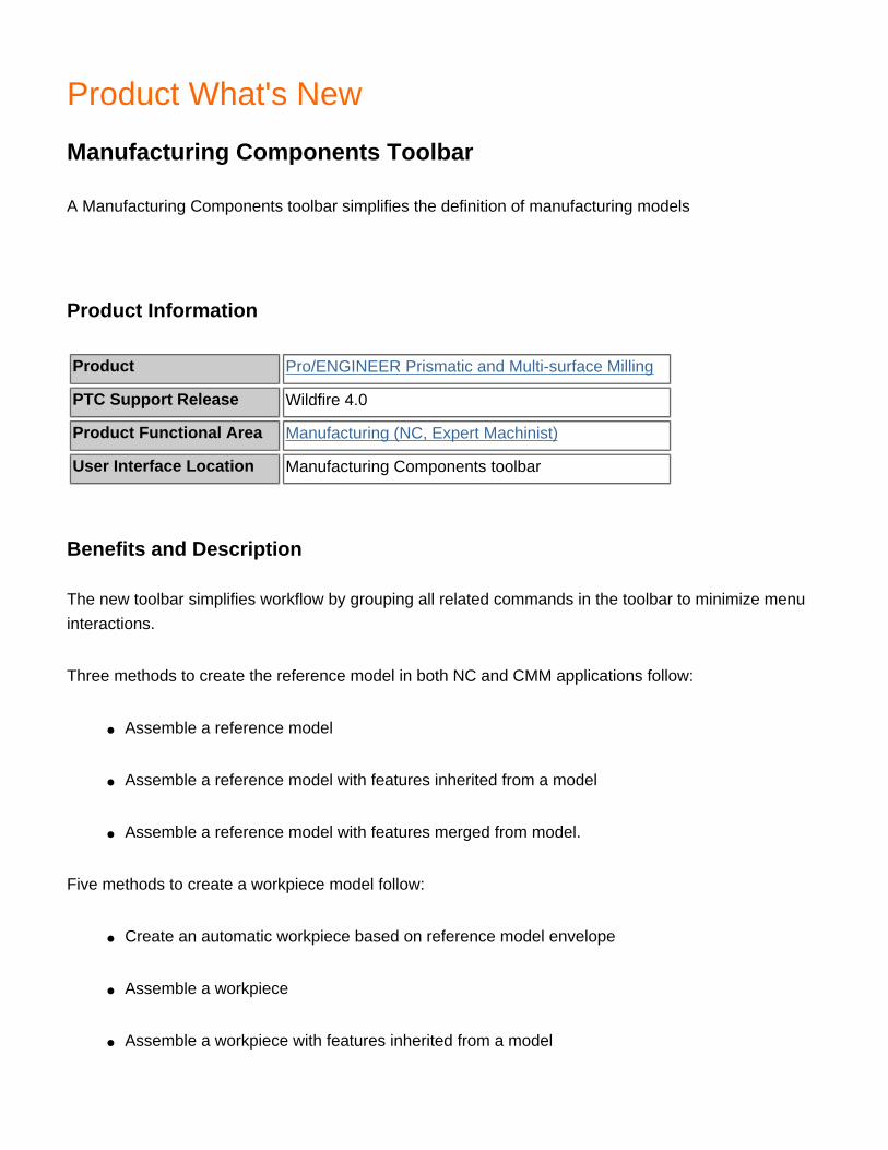
Product What's New
Manufacturing Components Toolbar
A Manufacturing Components toolbar simplifies the definition of manufacturing models
Product Information
Product Pro/ENGINEER Prismatic and Multi-surface Milling
PTC Support Release Wildfire 4.0
Product Functional Area Manufacturing (NC, Expert Machinist)
User Interface Location Manufacturing Components toolbar
Benefits and Description
The new toolbar simplifies workflow by grouping all related commands in the toolbar to minimize menu interactions.
Three methods to create the reference model in both NC and CMM applications follow:
● Assemble a reference model
● Assemble a reference model with features inherited from a model
● Assemble a reference model with features merged from model.
Five methods to create a workpiece model follow:
● Create an automatic workpiece based on reference model envelope
● Assemble a workpiece
● Assemble a workpiece with features inherited from a model

● Assemble a workpiece with features merged from a model● Create a manual workpiece

Product What's New
NC and CMM Parameters Setup User Interface
The redesign of the NC and CMM Parameters Setup dialog box simplifies the definition of tool paths.
Product Information
Product Pro/ENGINEER Prismatic and Multi-surface Milling
PTC Support Release Wildfire 4.0
Product Functional Area Manufacturing (NC, Expert Machinist)
User Interface Location Select the NC Parameter Setup icon during NC sequence definition.
Benefits and Description
The more intuitive dialog box helps quickly define tool paths or measuring steps. The same dialog box is used in the Process Manager, Menu Manager, and in customizing cut motions when defining parameters.
● Basic parameters are illustrated with graphics.
● Parameters are grouped by category and only pertinent parameters are displayed.
● The dialog box is customizable, including the choosing of your language for the parameter name.
● Descriptions or comments can be associated to each NC parameter.
● Sorting and searching tools simplify the locating of a parameter.
● A standard Pro|ENGINEER relation dialog box can be used to define parameters, including a multiline relation.
● NC parameters are stored in XML file format to improve portability.
● Parameter names and values can be output automatically to CL file using PPRINT.

Product What's New
Roughing, Re-roughing, and Finishing Tool Paths
In the Process Manager, you can directly create the roughing, re-roughing, and finishing tool paths
Product Information
Product Pro/ENGINEER Prismatic and Multi-surface Milling
PTC Support Release Wildfire 4.0
Product Functional Area Manufacturing (NC, Expert Machinist)
User Interface Location Process Manager icon or Manufacture > Process Manager
Benefits and Description
Using the Process Manager for these operations, you can:
● Define steps using the step-editing dashboard in the Process Manager.
● Capture step definitions in XML-based manufacturing templates for data reuse.
● Use steps as part of a manufacturing annotation feature for process extraction.
● Create a new step from a manufacturing template including automatic assignment of references based on type and name if the config.pro option.MFG_AUTO_REF_MFG_TEMPLATE is set to YES.
These operations also apply to all the other NC sequence types already supported by the Process Manager, including the new corner machining and 3-axis trajectory.

Product What's New
VERICUT Version 6.0
VERICUT Version 6.0 has been integrated into Pro/ENGINEER.
Product Information
Product Pro/ENGINEER Prismatic and Multi-surface Milling
PTC Support Release Wildfire 4.0
Product Functional Area Manufacturing (GPOST, Vericut)
User Interface Location Machining > NC Sequence > Play Path > NC Check
Benefits and Description
The Pro/ENGINEER interface supports the XML-based project definition of VERICUT version 6.0 shipped with Pro/ENGINEER Wildfire 4.0
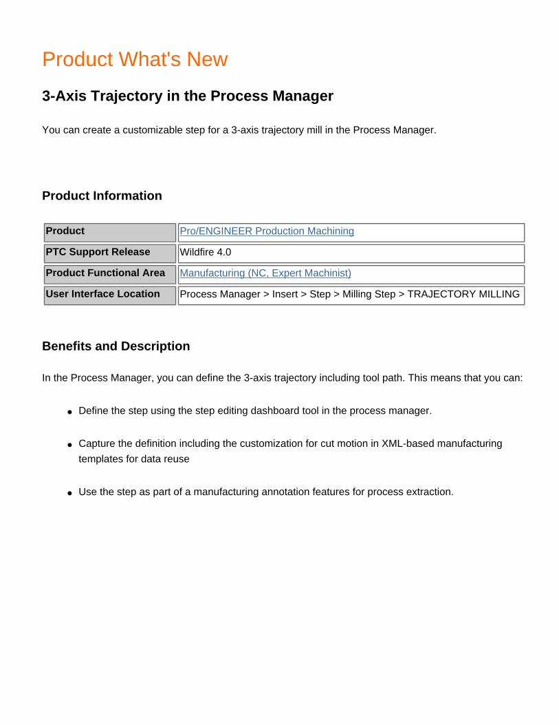
Product What's New
3-Axis Trajectory in the Process Manager
You can create a customizable step for a 3-axis trajectory mill in the Process Manager.
Product Information
Product Pro/ENGINEER Production Machining
PTC Support Release Wildfire 4.0
Product Functional Area Manufacturing (NC, Expert Machinist)
User Interface Location Process Manager > Insert > Step > Milling Step > TRAJECTORY MILLING
Benefits and Description
In the Process Manager, you can define the 3-axis trajectory including tool path. This means that you can:
● Define the step using the step editing dashboard tool in the process manager.
● Capture the definition including the customization for cut motion in XML-based manufacturing templates for data reuse
● Use the step as part of a manufacturing annotation features for process extraction.

Product What's New
Customizable Names for Table Headers
You can customizable header names in the Process Table for manufacturing.
Product Information
Product Pro/ENGINEER Production Machining
PTC Support Release Wildfire 4.0
Product Functional Area Manufacturing (NC, Expert Machinist)
User Interface LocationSelect Process Manager > Process View Builder icon > Column Labels Setup icon
Benefits and Description
Table header names for parameters used in the columns in the Process Table can be customized to company standards and local language. The report and the exported CSV file include the customized name.

Product What's New
Turn Profile User Interface
You can define a Turn Profile using a dashboard user interface.
Product Information
Product Pro/ENGINEER Production Machining
PTC Support Release Wildfire 4.0
Product Functional Area Manufacturing (NC, Expert Machinist)
User Interface Location Turn Profile icon or Insert > Manufacturing Geometry > Turn Profile
Benefits and Description
The Turn Profile dashboard streamlines workflow and adds flexibility to the creation of turn profile features used in turning tool paths. The following commands are available:
● Turn envelop
● Start and End surfaces
● Curve
● Sketch
● Cross-section
You can preview the calculated curve and directly manipulate the profile for the start and end definition, location, direction, and shape.

Product What's New
Creation of Symmetry Planes
You can create a symmetry plane on the facet geometry.
Product Information
Product Pro/ENGINEER Reverse Engineering
PTC Support Release Wildfire 4.0
Product Functional Area Surfacing - Facet Modeling
User Interface Location Insert > Facet Feature
Benefits and Description
The Facet feature tool analyzes the facets and calculates the best plane of symmetry. You can use this plane as a trimming plane.

Product What's New
Display of Outlier points
The display of outlier points are now previewed
Product Information
Product Pro/ENGINEER Reverse Engineering
PTC Support Release Wildfire 4.0
Product Functional Area Surfacing - Facet Modeling
User Interface Location Insert > Facet Feature
Benefits and Description
When you preview outlier points, the points to be removed are highlighted. This allows for easier visualization of the resulting data set.

Product What's New
Filling of Holes
The definition and display of holes for filling in facet models is much improved.
Product Information
Product Pro/ENGINEER Reverse Engineering
PTC Support Release Wildfire 4.0
Product Functional Area Surfacing - Facet Modeling
User Interface Location Insert > Facet Feature
Benefits and Description
The Fill Hole command has the following improvements:
● Upon the selection of the command, all open edges (holes) are highlighted in blue.● Edges selected for filling change from blue to red.● Edges that have been filled change from red to yellow.● Holes to be filled can be defined by selecting an edge, choosing to fill all, or choosing to fill all
holes below a percentage of the model size.

Product What's New
Offsetting and Thickening of Facets
You can offset and thicken facet models.
Product Information
Product Pro/ENGINEER Reverse Engineering
PTC Support Release Wildfire 4.0
Product Functional Area Surfacing - Facet Modeling
User Interface Location Insert > Facet Feature
Benefits and Description
Facet models can be offset or thickened in either direction:
● The Offset command creates an offset of an open or closed manifold of facets. This removes the original facet model.
● Copy and Paste commands enable the duplication of facet models for use with the Offset command.
● The Thicken check box offsets the facet model and then builds side walls to create a closed volume of facets.
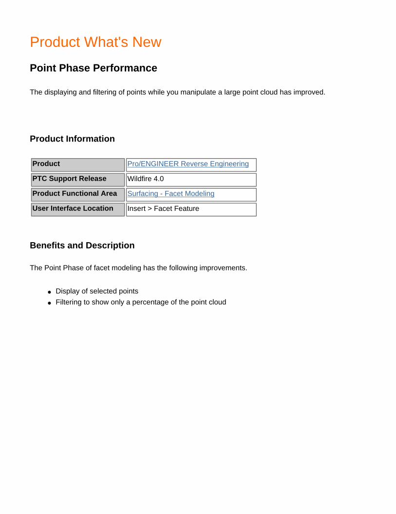
Product What's New
Point Phase Performance
The displaying and filtering of points while you manipulate a large point cloud has improved.
Product Information
Product Pro/ENGINEER Reverse Engineering
PTC Support Release Wildfire 4.0
Product Functional Area Surfacing - Facet Modeling
User Interface Location Insert > Facet Feature
Benefits and Description
The Point Phase of facet modeling has the following improvements.
● Display of selected points● Filtering to show only a percentage of the point cloud

Product What's New
Return to the Points Phase
You can return to the Point Phase from the Wrap Phase in Facet modeling.
Product Information
Product Pro/ENGINEER Reverse Engineering
PTC Support Release Wildfire 4.0
Product Functional Area Surfacing - Facet Modeling
User Interface Location Insert > Facet Feature
Benefits and Description
If the wrap of a point cloud is unsatisfactory, you can return to the Point Phase for further point manipulation.

Product What's New
Selection of Connected Facets
You can select all connected facets in one command.
Product Information
Product Pro/ENGINEER Reverse Engineering
PTC Support Release Wildfire 4.0
Product Functional Area Surfacing - Facet Modeling
User Interface Location Insert > Facet Feature
Benefits and Description
With the new option, you can select all connected facets in one set. You can quickly select and then delete large portions of a facet model.

Product What's New
Trimming Facets by a Plane
You can trim facets by a datum plane.
Product Information
Product Pro/ENGINEER Reverse Engineering
PTC Support Release Wildfire 4.0
Product Functional Area Surfacing - Facet Modeling
User Interface Location Insert > Facet Feature
Benefits and Description
The trimming of a facet model by a datum plane provides the following benefits:
● Reduces the amount of data in the facet model.● Keeps only one-half of a symmetrical part when used in conjunction with the Symmetry Plane
command.

Product What's New
Color Assignment for Split Surfaces
Colors are assigned automatically to Split and Slider surfaces during component extraction.
Product Information
Product Pro/ENGINEER Tool Design
PTC Support Release Wildfire 4.0
Product Functional Area Mold Design & Casting
User Interface Location View > System Colors > Geometry tab > Volume Split or Slider Volume
Benefits and Description
During extraction, user defined colors are automatically assigned to split and slider surfaces. With the colors, a manufacturing engineer can easily differentiate metal to plastic contact surfaces from metal to metal contact (shutoff) surfaces and use the appropriate machining methods.


