What's New in Edgecam 2013 R1 · What’s New in Edgecam 2013 R1 This document highlights new...
60
What’s New in Edgecam 2013 R1 This document highlights new product features and enhancements in Edgecam 2013 R1, including machining enhancements for milling and turning and improved performance. To run Edgecam and Part Modeler 2013 R1, the expiry date in the license must be September 2012 or later.
Transcript of What's New in Edgecam 2013 R1 · What’s New in Edgecam 2013 R1 This document highlights new...

What’s New in Edgecam 2013 R1
This document highlights new product features and enhancements in Edgecam 2013 R1, including
machining enhancements for milling and turning and improved performance.
To run Edgecam and Part Modeler 2013 R1, the expiry date in the license must be
September 2012 or later.

www.edgecam.com
What’s New in Edgecam 2013 R1 2 of 60
Contents
‘WHAT’S NEW’ DOCUMENT OVERVIEW ............................................................................................. 4
IMPORTANT INFORMATION ............................................................................................................... 5
New Product
EDGECAM WIRE EROSION .................................................................................................................. 6
Machining Enhancements
NEW ROUGH PROFILE CYCLE .............................................................................................................. 7
ROUGHING - WAVEFORM IMPROVEMENTS ....................................................................................... 8
MOVING THE SUB-SPINDLE - OPTION TO RETURN HOME WITHOUT THE PART .................................. 9
TURNING TOOL DIALOG - MACHINING OF INTERNAL HOLES & REVERSE RADIAL TOOLS .................. 10
FIVE AXIS MILLING DIALOG - DIRECT PICKING ON MODEL ................................................................ 11
Improved Collision Avoidance (3 to 5-Axis and Five Axis Cycles) ............................................... 11 New Advanced Five Axis Options ................................................................................................. 11 5 axis cycle - separate process and 64-bit support ....................................................................... 11
PROFILING - BREAK CORNER OPTIONS FOR PROFILING CYCLE.......................................................... 12
SET SAFE START POINT FOR MILL/TURN (BACKGROUND PROCESSING) ........................................... 13
Solid Machinist Enhancements
AUTOMATICALLY FINDING FEATURES - FEATURE FINDER RECOGNISES U AND V STYLE GROOVES ... 14
AUTOMATIC FEATURE FINDER - INTERNAL HOLES ............................................................................ 15
Part Modeler Enhancements
FEATURE FINDER - HOLES ................................................................................................................. 16
WINDOW SELECTION INTRODUCED FOR REMOVE FACE PROCEDURES ............................................ 17
ENHANCEMENTS TO DRAWING APPLICATION ................................................................................. 18
ACTIVE COMPONENT INDICATED IN MODEL WINDOW .................................................................... 19
Ease of Use Enhancements
IMAGES WITHIN DIALOGS ................................................................................................................ 20
FEATURE ORDERING ENHANCEMENTS ............................................................................................. 21
Planning Board – Automatic Ordering ......................................................................................... 22
DESIGN - STOCK CREATION AND EDITING IMPROVEMENTS ............................................................. 23
www.edgecam.com
What’s New in Edgecam 2013 R1 3 of 60
Other Enhancements
SIMULATOR ENHANCEMENTS .......................................................................................................... 24
Improved simplification of stock from Simulator .......................................................................... 24 Specifying a Rewind Point ............................................................................................................ 24 Spin Driven Milling Holders ......................................................................................................... 24
EDGECAM - AUTODESK VAULT INTERFACE ....................................................................................... 25
TOOLSTORE ENHANCEMENTS .......................................................................................................... 26
Use of CSV, MEG and STL Graphics for Milling Tools and Probes ............................................ 26 Taper Ball Nose check box ............................................................................................................ 26 Command Line Conversion of Solid to MEG ................................................................................ 26
CODE WIZARD ENHANCEMENTS ...................................................................................................... 27
Support for drilling rotary holes from inside and outside ............................................................. 27 Turning Templates for Siemens ..................................................................................................... 27 Templates – Output from Move to Toolchange / Home ................................................................ 27
OTHER CHANGES .............................................................................................................................. 28
Thread Database ........................................................................................................................... 28 Use Max RPM from the Code Generator ...................................................................................... 28 Update Stock also functions as a Synchronisation command ....................................................... 28 Feature Find - groove features ..................................................................................................... 28 Zoom In/Out .................................................................................................................................. 28 Preferences dialog - New Solid Assembly Preferences for Solids................................................. 28 Direction / Start Arrow for Turn Cycles ....................................................................................... 29 Thread Mill - New "Plunge in Centre" modifier ........................................................................... 29 Partial Hole Feature Template ..................................................................................................... 29 Transfer of External Threads from SolidWorks ............................................................................ 30
LICENSING ........................................................................................................................................ 31
NEW LICENSES ....................................................................................................................................... 31 Edgecam Wire System - Product Code ENPWE-0 ........................................................................ 31 Edgecam Vault Module - Product Code ENVLT-0 ....................................................................... 31 NCSIMUL Link Module - Product Code ENSIM-0 ....................................................................... 31
CHANGES TO EXISTING LICENSES ................................................................................................................ 31 4/5 Axis Positioning now included in Standard Milling and Standard Production licenses ......... 31 Advanced 5 Axis now included in the Edgecam Educational license ............................................ 31 Probing now included in the Educational and Homework licenses .............................................. 31
MAINTENANCE DATABASE REPORT ................................................................................................. 32
NEW FEATURES IN VERSION 2012 R2 ............................................................................................... 33

www.edgecam.com
What’s New in Edgecam 2013 R1 4 of 60
‘What’s New’ Document Overview
Purpose of this Document and Other Sources of Information
The purpose of the document is to highlight new and changed items in the current release. Non-
release specific information such as installation and licensing information, system requirements and
CAD Links information can be found in the relevant document.
For help with your installation, please refer to the Installation Guide. This is available from the DVD
or the Help sub-menu in the Edgecam program group.
For help with licensing your standalone or network license, please refer to the Licensing Guide. This
is available from the Help sub-menu in the Edgecam program group, the CLS menu and the License
Manager dialog.
For information on system requirements and supported CAD systems, please refer to the Installation
Guide.
Targeted Information inside Edgecam and Other Programs
In addition to this document, ‘targeted’ information on new items is available in the dialog help and
user guides for other applications. This allows you to focus on new features/enhancements for a
specific program or the cycle you are currently working on, for example.
Dialogs that have new functionality or where the cycle behaviour has changed have an additional
‘What’s New’ tab in the help. This explains what has been added to the dialog or changed in this
release.
What’s new topic(s) have been added to help files for other programs, such as Code Wizard, Code
Generator, and ToolStore etc. This only lists new functionality for that program, allowing you to focus
on those items.
The Development History of Edgecam
Additional functionality and enhancements are developed with each release of Edgecam software. For
an overview of new features and enhancements in the last release, please refer to New Features in
Version 2012 R2.
For a summary of new features in previous releases, please visit the History section of the Edgecam
website.

www.edgecam.com
What’s New in Edgecam 2013 R1 5 of 60
Important Information
Windows XP Support
Future releases of Edgecam will not support Windows XP:
Edgecam 2013 R1 will support Windows XP.
Edgecam 2013 R2 will install and run on Windows XP. However, the user will be warned that it is not a supported Operating System.
Windows 8 Support
Windows 8 will be officially supported for Edgecam 2013 R2. However, Edgecam 2013 R1 does install on Windows 8 and we are not aware of any specific issues at this time.
Changes to DVD shipments
Starting at the next release, 2013 R2, all future Edgecam R2 releases by default will be available as a download only and all future R1 releases will be shipped on DVD as well as being available for download. We are currently implementing a new software download manager that will ensure that the downloads are delivered to you in a fast and efficient manner. The download manager will also ensure that interrupted downloads are resumed from where they stopped. These changes mean that you can download the software as soon as it is released, however, if you would still like to receive a DVD at the R2 releases please contact our Support team.
Edgecam Wire Erosion
A new Edgecam Wire Erosion product (license code ENPWE-0) is introduced in this release. The old Wire Erosion product (license code EN3W0-0) is no longer available to purchase, and it's license has been renamed to 'Legacy Wire Erosion'. For customers who have the Legacy Wire Erosion product, it will continue to work in this Edgecam release. If you are interested in the new Wire Erosion product, please click here for more information and/or contact your Sales representative.

www.edgecam.com
What’s New in Edgecam 2013 R1 6 of 60
Edgecam Wire Erosion
Edgecam’s new Wire Erosion product is based on the industry leading Vero PEPS Wire product and offers an intuitive environment for the comprehensive programming of all Wire EDM machine tools. Including a comprehensive library of proven post-processors and knowledge-based cutting schemes as standard. Users can select from one of the pre-defined machining strategies such as 'Unattended night runs' and 'Attended day runs' or, alternatively, define their own.
Features include:
Pre-configured code generators, optionally configurable.
Knowledge-based cutting schemes.
Roughing and finishing cuts easily applied to multiple punches / dies.
Reverse cutting with offsets and cutting technology changes.
Multiple strategies for corner types; including square ISO and conic.
Toolpath display indicators showing thread wire, cut wire and program stop positions.
No-core pocket destruction of round and irregular shapes.
No-core pocket destruction considers pre-hole diameter to eliminate air cuts and reduce cycle time.
Note: Edgecam Wire Erosion is now available to purchase and its product code is ENPWE-0.

www.edgecam.com
What’s New in Edgecam 2013 R1 7 of 60
New Rough Profile Cycle
This is a new cycle that replaces the Rough Profile cycle.
It is available with all Turning and Production Licenses.
The Rough Profiling cycle removes material in a series of cuts parallel to the input profile and is typically used for roughing free form profiles from free form stock billets. It is also useful for cutting materials where it is beneficial to minimise re-entrant cutting as it keeps the tool in contact with the material for longer.
Benefits of the new cycle include:
Cycle is optionally stock aware to eliminate air cuts and reduce cycle time.
Intelligent stock entry and exit.
Support for controller tool offset i.e. G41/G42.
Possibility to enter a constant cut depth or different cut depths for X and Z.
Specify ZX or Constant Offset finishing allowance.
Possibility to enter different offsets for each face element.
Option to stop after a specified no. of cuts, return to a safe swarf clearance position, stop the machine, clear the swarf then carry on.
The old Rough Profile cycle has been removed from the default user interface but can be retrieved using Customise -> Commands -> Turn Cycles.

www.edgecam.com
What’s New in Edgecam 2013 R1 8 of 60
Roughing - Waveform Improvements
Roughing Waveform has been improved:
The Waveform strategy now has the
ability to set the Approach Type;
Helix and Pre-drill are possible. It
works in the same way as the other
strategies. A 10% bigger drill tool is
expected for the pre-drill option.
Waveform pattern has been
improved to avoid unnecessary
cutting interruptions when opening
the initial 'virtual pocket'. The
transition between this area and
actual toolpath is much smoother.
Percentage Plunge Feed added to Approach Options The Plunge feedrate for approach moves can now be specified as a percentage of the Plunge feedrate on the General tab. This option is available for all Roughing strategy types. Clean Up Final Pass added to Control Options Some machines tools, due to the "Look Ahead" calculation and the high feeds, may leave pegs in the material showing unmachined areas. These pegs would be removed if the feeds were reduced, meaning that the toolpath is correct but, due to the "Look Ahead" calculation, the machine tool is avoiding those areas. Clean Up Final Pass has been added to the Control options which will add a pass at the end of the area to ensure that all material has been removed.

www.edgecam.com
What’s New in Edgecam 2013 R1 9 of 60
Moving the Sub-spindle - Option to
Return Home without the part
The sub spindle can be docked to support the part for a machining process after which it may be sent back to its home position without the part. Previously, the stock was always returned home with the sub spindle - this is now optional.
There is an additional code constructor:
Sub Spindle Retract Empty. This is used to format the NC code for the Return Home Without Part option.
Note
If the With Part option is selected, the sub spindle should be docked at its final grip position prior to returning home with the part. If it is not, a message is issued requesting you do this.

www.edgecam.com
What’s New in Edgecam 2013 R1 10 of 60
Turning Tool dialog - Machining of
Internal Holes & Reverse Radial
Tools
Machining of internal rotary holes has been improved to provide better access and handle situations which were previously not possible. Two situations are being improved:
Correctly handle internal holes when using a Radial tool. Typical work for very large parts where the whole turret can sometimes go inside the component to do machining.
Load a Reverse Radial tool. which on
an Index type turret will allow for
two situations (driven by machine
parameter).
Either load the tool at the front of
the turret (with special holder /
mounting mechanism) or load the
tool at the back of the turret.

www.edgecam.com
What’s New in Edgecam 2013 R1 11 of 60
Five Axis Milling dialog - Direct
Picking on Model
Previously, the Five Axis cycle had to use
geometry created from the solid, for
example, Edge Loops and Face Features. The
cycle can now pick edges and faces directly
from the model without having to create
Edge Loops or Face Features.
Improved Collision Avoidance (3 to 5-Axis and Five Axis Cycles)
In Edgecam 2013 R1, a new Remove Remaining Collisions option has been introduced. This option,
when checked, will remove any collisions remaining after the main checks have been completed by
retracting the tool away from the surface.
New Advanced Five Axis Options
In Edgecam 2013 R1, new Chaining Tolerance and Slow and Safe Path Creation options have been
introduced on the General tab:
Chaining Tolerance is an internal value, greater than zero, used for the toolpath generation.
The Chaining Tolerance might have an effect for a flat or slightly curved face where, since
less tool path points are generated, the toolpath has less information. In this situation the
chaining tolerance makes the toolpath accurate. However, if a smaller tolerance is selected,
more computing time is required.
When Slow and Safe Path Creation is checked, the Chaining Tolerance will be set to an
interval not longer than the maximum stepover distance. As with the Chaining Tolerance,
activating this parameter requires more computing time.
5 axis cycle - separate process and 64-bit support
In Edgecam 2013 R1, a 5 Axis cycle will always be moved into a separate process, regardless of whether Set Safe Start Point (SSSP) has been set.
A 64-bit version of the application has also been created (EdgeSrv5Axis64.exe).
This will improve situations where the cycle previously ran out of memory during calculation.

www.edgecam.com
What’s New in Edgecam 2013 R1 12 of 60
Profiling - Break Corner options for
Profiling Cycle
The Profiling cycle has been updated to
include options to break sharp corners with
either a radius or chamfer. This will reduce
secondary de-burring operations.

www.edgecam.com
What’s New in Edgecam 2013 R1 13 of 60
Set Safe Start Point for Mill/Turn
(Background processing)
Set Safe Start Position is now available in the
Mill/Turn environment. Turning cycles are
not affected.
The Safe Start Point can now be set up using
the options in the new Background
Processing tab:
Two safe points can be defined for
each turret when there is a Sub
Spindle. Only one is required when
no Sub Spindle is present.
Only Main Spindle points need to be
defined; Sub Spindle points will be
created automatically.
The initial setup allows you to specify the Safe Start Position for both milling and turning environments. The turn environment allows positions to be set for both turrets:

www.edgecam.com
What’s New in Edgecam 2013 R1 14 of 60
Automatically Finding Features -
Feature Finder recognises U and V
style grooves
Feature finder now recognises U and V style grooves and sets appropriate attributes.
This is useful for machining of such features using strategies.
The new Groove Type Attribute defines:
V style grooves need to have equal side wall angles.
U and V Style Grooves need to start and end at same level.
U and V style grooves can include a lead in corner radius or chamfer.
U style grooves need to have a full
180 degree base radius.
V style grooves can include a blend radius at its base.
V style grooves have Included Angle attribute.
U and V style grooves have Groove
Width attribute. This is the distance
across the top of the groove.
Groove features are put on a separate layer.

www.edgecam.com
What’s New in Edgecam 2013 R1 15 of 60
Automatic Feature Finder - Internal
Holes
Internal holes will not be found by Automatic Feature Finder if they are impractical to machine.
As a general rule, internal holes will not be found if the space (bore / cavity) before the start of the internal hole is either:
Less than 4 times the depth of the hole OR
Less than 4 times the diameter of the hole at the internal face.

www.edgecam.com
What’s New in Edgecam 2013 R1 16 of 60
Feature Finder - Holes
It is now possible to find holes from a
"dumb" model, add them to the model tree
and edit them, if required, within Part
Modeler.
This new introduction will.
Allow ALL "dumb" holes in the solid
model to be defined and edited
within Part Modeler.
Allow users to add extra information
to "dumb" holes, e.g. thread data.
Allow similar holes to be processed
as a group.
Allow similar holes to be processed
individually.

www.edgecam.com
What’s New in Edgecam 2013 R1 17 of 60
Window Selection Introduced for
Remove Face Procedures
It is now possible to use a window selection
to select multiple faces when using the
Remove Face procedure within Part Modeler.
This new function will:
Allow multiple faces of a feature to
be selected easily to allow removal
of the "dumb" feature.
Allow faces that are FULLY within a
window selection to be selected
(Left to Right window selection).
Allow faces that are PARTIALLY
within the window selection to be
selected (Right to Left window
selection).

www.edgecam.com
What’s New in Edgecam 2013 R1 18 of 60
Enhancements to Drawing
Application
Various enhancements have been made to
the Drawing Application within Part Modeler.
These include:
The introduction of "Force Aligned
Parallel" dimension button, found
on the "Modifier" Toolbar.
The introduction of the
"Construction" line button, found on
the "Locate" Toolbar. This button is
also available in the Model
application.

www.edgecam.com
What’s New in Edgecam 2013 R1 19 of 60
Active Component indicated in
Model Window
When two or more components are present
in the model space, the active (selected)
component is now indicated in the Model
Window by a red tick.

www.edgecam.com
What’s New in Edgecam 2013 R1 20 of 60
Images within Dialogs
The dialog mechanism within Edgecam has now been changed to an XML format which will benefit users and developers.
This new feature will:
Allow images to be used within dialog boxes to help explain modifiers. For Edgecam 2013 R1, images have been added to the Automatic Feature Finder dialog.
Allow dialogs to be more flexible in design, enabling different styles of dialogs to be implemented within Edgecam.
Allow greater customisation of dialogs within Edgecam.

www.edgecam.com
What’s New in Edgecam 2013 R1 21 of 60
Feature Ordering Enhancements
Feature Finder internally groups features with similar attributes prior to performing a nearest next sort.
Nearest Next
Mill features on the same solid that share the same CPL level are now ordered using a "nearest next" logic. This ensures that the features are in a reasonable machining order for use by Strategy Manager and Planning Board. This is primarily needed in the milling environment where you have a plate with many pockets.
Feature Find internally groups features with similar attributes before performing a "nearest next" sort and automatically ordering the features:
Closed Pockets, Open Pockets and Open Mill features are considered together for the purpose of internal grouping. The feature attributes that are considered for internal grouping are MaxXyRadius (range +/- 50%), Depth (range +/- 50%), Lower Radius (exact) and MinimumXYRadius (exact). Each feature group starts at the bottom left.
In the example, all attributes are identical except for the MaxXyRadius (The radius of the greatest circle fitting inside the top contour).
Internal groups have been identified by colour and these groups would typically be roughed / rest roughed with different tooling sets. However, all of these features have the same MinimumXYRadius and would, therefore, be finished with the same tool. The feature order used for roughing is, therefore, not necessarily useful for finishing.
Features on Parallel CPLs (Z axis) are considered together
The predefined manufacture ordering now groups all mill / hole features on CPLs which share the same Z same direction together. This ensures that the order of features is highest level first irrespective of CPL. Previously, mill and hole features were sorted by CPL and then CPL level.
Previously, if Feature Find was run more than once on different CPLs, features could be identified on different CPLs which shared the same Z direction. In this situation, ordering features by CPL could lead to features on a lower level being ordered before features on a higher level.

www.edgecam.com
What’s New in Edgecam 2013 R1 22 of 60
Planning Board – Automatic Ordering
Feature Find automatically orders features into a logical order for manufacture. Machining Strategies can subsequently be assigned to each feature. Typically, a feature will be assigned a minimum of one roughing and one finishing strategy. The Planning Board can now be automatically ordered based on the priority setting assigned to each strategy. Strategy Manager (File Properties) is used to assign a priority to a strategy.
Automatic Ordering has been added to the
Planning Board:
In Strategy Manager, File Properties specify a priority for each strategy. When the planning board is populated, it is automatically ordered based on this priority setting.
In the sample set of Edgecam strategies, priorities have been set so that all rough turning is done before finish turning and rough milling is done before finish milling.
Automatic Ordering is enabled by selecting Auto Sort Planning Board on the General tab of the Preferences dialog or can be done by pressing the Sort by priority button.

www.edgecam.com
What’s New in Edgecam 2013 R1 23 of 60
Design - Stock creation and editing
improvements
A number of improvements have been made to the Design Stock command:
Stock Profile can now be consistently created from a closed shape without rendering problems.
Arcs are no longer split into several segments of lines.
Profile Stocks now support hollow/holes/through pockets.
Tube stocks for turning and milling.
Ability to edit stocks and re-pick geometry or depth, retaining the original type.

www.edgecam.com
What’s New in Edgecam 2013 R1 24 of 60
Simulator Enhancements
Improved simplification of stock from Simulator
The previous simplifier could take minutes to simplify complicated stock, the new simplifier (using OpenMP-based parallelism and a much improved algorithm) should take a couple of seconds (on a Core I7 quad core) to simplify very complicated stock (100MB+ STL) and fractions of seconds for anything more reasonably sized.
The simplifier is utilised by the Update Stock command; when the resultant stock exceeds the size stated on the dialog, the simplification is performed. It is also used when saving STL stock directly from the simulator, when requested.
Specifying a Rewind Point
Simulator has been enhanced in version 2013 R1 and you can now specify a Rewind Point at any point in the instruction list.
Spin Driven Milling Holders
Simulator has been enhanced in version 2013 R1 to show driven milling tool holders and tool graphics as spun; this is optional with the default being spun. If your driven mill holders include more than just the spinning holder, for example, the holder graphic includes the complete turret, this setting should be unchecked.

www.edgecam.com
What’s New in Edgecam 2013 R1 25 of 60
Edgecam - Autodesk Vault Interface
The Vault Interface in Edgecam allows users to manage their data within Autodesk Vault 2013. Note that this functionality is supported for Autodesk Vault 2013 and above.
The Vault functionality implemented for Edgecam is available in all versions of Autodesk Vault 2013 (Vault Basic, Vault Workgroup, Vault Collaboration and Vault Professional).
Autodesk Vault
Autodesk Vault is a data management tool
integrated with Autodesk Inventor Series,
Autodesk Inventor Professional, AutoCAD
Mechanical, AutoCAD Electrical, and Civil 3D
products. It helps design teams track work in
progress and maintain version control in
multi-user environments. It allows them to
organize and reuse designs by consolidating
product information and reducing the need
to re-create designs from scratch. Users can
store and search both CAD data (such as
Autodesk Inventor, DWG, and DWF files) and
non-CAD documents (such as Microsoft
Word and Microsoft Excel files).

www.edgecam.com
What’s New in Edgecam 2013 R1 26 of 60
ToolStore Enhancements
Use of CSV, MEG and STL Graphics for Milling Tools and Probes
Some Tooling suppliers have made available tool and tool holder models as STEP files. These files can be loaded into Edgecam and saved as MEG files to be used in the ToolStore:
A Paste button is now available in Tool Geometry for Milling and Probes enabling the use of
CSV, MEG and STL files as graphics.
No Shank geometry is available with tools using MEG or STL graphics.
The Simulator will automatically generate a 2D revolved profile for tools using MEG and STL
graphics.
Taper Ball Nose check box
Previously, a Taper Ball Nose was defined with a Taper, Corner Radius and by leaving the Small Diameter blank. However, this was not obvious and caused confusion.
A new Ball Nose check box has been added which, when checked, will grey out the Small Diameter and Flute Length as they are automatically calculated.
Command Line Conversion of Solid to MEG
Some Tooling suppliers have made available tool and tool holder models as Solid CAD files. These files can be loaded into Edgecam and saved as MEG files to be used in the ToolStore:
If you have many tool models to convert, then this command line program can be used to
automate the process.
The program can translate and rotate the part, if required, to achieve the correct orientation
for ToolStore.
Note: The ability to convert the CAD file is dependent on having an Edgecam license for that model type.

www.edgecam.com
What’s New in Edgecam 2013 R1 27 of 60
Code Wizard Enhancements
Support for drilling rotary holes from inside and outside
Edgecam 2013 R1 introduces support for the machining of Internal Holes and Reverse Radial tools. A new Rotate for Reverse Mount setting on the Machine Parameters Dialog - Turret tab allows tools to be mounted on the front or back of a turret.
Turning Templates for Siemens
The default Siemens adaptive turning template has been changed to have a generic Siemens format. In order to retain the WFL capability, new .CGX files have been added to the release for those machines in Inch and Metric units.
Existing .CGD files for any Siemens controller should not be affected and should update correctly.
The revised templates are:
adaptive-siemens.cgt and adaptive-siemens-inch.cgt which are generic "Siemens" templates.
adaptive-siemens wfl.cgx and adaptive-siemens wfl-inch.cgx which are generally formatted for WFL controllers. These templates equate to the previous Siemens versions supplied with Edgecam 2012 R2.
Templates – Output from Move to Toolchange / Home
The Code Generator and Templates have been enhanced to provide more consistent and useful output from the Move to Toolchange and Move to Home instructions.
The Move to Toolchange and Move to Home instructions will now set, using the XMOVE, YMOVE, ZMOVE system variables, the true tooltip position in current CPL coordinates. This change should remove high coordinates resulting from moves immediately after a Move to Toolchange or Move to Home instruction which would potentially cause an overtravel.
The templates have been enhanced, as follows:
The XMOVE, YMOVE, and ZMOVE tokens at Move to Toolchange and Move to Home now
always contain the tooltip position on current CPL. Not available on Milling templates.
The XTOOL, YTOOL, ZTOOL, XHOME, YHOME and ZHOME tokens follow the Values of Tool
Change Home NC-Style option (Tool Change Tab), where:
o Gauge Adjusted Position will compensate for TOOLXSET and TOOLZSET.
o Machine Datum Coords are the turret centre position.
o Current CPL Coords will give the same result as XMOVE, YMOVE and ZMOVE.
Note:
No changes are expected on post processors with U0V0W0 output style.
Please check your post processor carefully on this area after the update.

www.edgecam.com
What’s New in Edgecam 2013 R1 28 of 60
Other Changes
Thread Database
The Thread Database (threaddata.mdb) location is now defined by the ToolStore Support files folder
and can, therefore, be shared by all users on a network. Users that use a network location for the
Toolstore will now use the Thread Database from that area automatically. Previously, Edgecam always
used the ..\Program Files\..\cam\TStore folder.
Use Max RPM from the Code Generator
A modifier has been added to the Spindle Tab on ToolChange command.
When Use Max RPM from the Code Generator is checked, the new Max RPM will be read
automatically if the Code Generator is edited or changed.
Update Stock also functions as a Synchronisation command
In turning, when there is more than one turret, the Update Stock command also functions as a
Synchronisation command because it is inserted in the instruction browser for each turret. It will also
generate a Sync Point in the NC code.
Feature Find - groove features
A unique layer and colour has been added for groove features.
Zoom In/Out
The default behaviour is to zoom about the mouse position. Previously, Edgecam zoomed about the centre of the screen.
Preferences dialog - New Solid Assembly Preferences for Solids
A new option called Granite Assembly Level Features has been added to the Solids Tab.

www.edgecam.com
What’s New in Edgecam 2013 R1 29 of 60
Direction / Start Arrow for Turn Cycles
In Turn Cycles, the Direction / Start Arrow displayed when picking geometry was the same as milling which showed the side to machine. This gave an incorrect impression for the turn cycles as the tool controls side. The image is now is a simple arrow to avoid confusion.
Thread Mill - New "Plunge in Centre" modifier
A new Plunge in Centre check box has been added to the Lead Tab:
When checked, the tool will plunge down the centre of the hole.
When unchecked, the tool will plunge at the start of the lead in.
The cycle used to always plunge centre, but on large threads there may be an obstruction in the
centre, such as a fixture bolt and the time to feed from centre to edge could be wasted time.
The New option is on by default to maintain the old behaviour.
Partial Hole Feature Template
It is now possible to define parts (elements) of holes and make them into Hole Feature Templates.
Partial Hole Feature Templates can be created by defining the parameters for part of the hole and then setting the Match To Subset flag to Yes.
The partial hole will be saved to a Hole Feature Template (*.ft).

www.edgecam.com
What’s New in Edgecam 2013 R1 30 of 60
Transfer of External Threads from SolidWorks
It is now possible to transfer external threads from SolidWorks.

www.edgecam.com
What’s New in Edgecam 2013 R1 31 of 60
Licensing
New Licenses
Edgecam Wire System - Product Code ENPWE-0
A new Edgecam Wire Erosion system license is introduced in this release to offer Wire EDM 2 and 4 Axis cycles for the comprehensive programming of all Wire EDM machines tools. It includes a comprehensive library of proven post-processors and knowledge-based cutting schemes as standard. The old Wire Erosion product (license code EN3W0-0) is no longer available to purchase, and it's license has been renamed to 'Legacy Wire Erosion'.
Edgecam Vault Module - Product Code ENVLT-0
A new Edgecam Vault module license is now available. This allows you to manage your data within Autodesk Vault 2013 using the Vault Interface in Edgecam. Note that this functionality is supported for Autodesk Vault 2013 and above. The Vault functionality implemented for Edgecam is available in all versions of Autodesk Vault 2013 (Vault Basic, Vault Workgroup, Vault Collaboration and Vault Professional). The Edgecam PC must have the Autodesk Vault Client software installed on it. Note that one of the prerequisites for the installation of the vault client is a qualifying Autodesk CAD product, i.e. Autodesk Inventor (Autodesk Inventor View and Autodesk Inventor LT are not qualifying CAD products).
NCSIMUL Link Module - Product Code ENSIM-0
A new Edgecam module license that provides a link to the NCSIMUL product is now available. The link transfers NC code, stock and tooling information directly to NCSIMUL to simulate the machining. A copy of NCSIMUL with appropriate machine tool graphics (purchased separately from NCSIMUL agents) must also be installed on the Edgecam PC.
Changes to Existing Licenses
All of the licensing changes below will be available when using Edgecam 2013 R1, without the need for a license update.
4/5 Axis Positioning now included in Standard Milling and Standard Production licenses
The Standard Milling and Standard Production licenses now include the 4/5 axis positioning capability. Previously, this was only available on the Advanced and Ultimate Milling and Production licenses.
Advanced 5 Axis now included in the Edgecam Educational license
The Edgecam Educational license now includes access to the Advanced 5 Axis cycle. The Advanced Five Axis cycle is an extension of the standard 5 axis cycle. The cycle has a graphical dialog with interactive geometry selection and extends the functionality available in the standard 5 axis cycle, offering additional calculation methods.
Probing now included in the Educational and Homework licenses
The Edgecam Educational and Homework licenses now include access to the Probing cycles. This enables insertion of probing macros for part setup into the Edgecam machining sequence, removing the need to insert probing instructions after post processing.

www.edgecam.com
What’s New in Edgecam 2013 R1 32 of 60
Maintenance Database Report
For a full list of maintenance items resolved in Edgecam 2013 R1, please refer to the Maintenance
Database Report.

www.edgecam.com
What’s New in Edgecam 2013 R1 33 of 60
New Features in Version 2012 R2
Below is an overview of new features and enhancements in the last release.
For a summary of new features in previous releases, please visit the History section of the Edgecam
website.

www.edgecam.com
What’s New in Edgecam 2013 R1 34 of 60
Quill Support in Milling
Edgecam 2012 R2 introduces quill support. This
allows you to program a secondary Z axis (Z2) on
milling machines for use by Edgecam, Simulator
and Code Generator. The secondary Z axis can be
in the head or the table.
In Code Wizard, specify parametric or
custom quill graphics
New command to select the currently
active Z axis in Edgecam
Simulation of quill movements and collision detection
Note
The new functionality is available with
Advanced Mill/Advanced Production
and above.
To access the new quill functionality
your Code Wizard documents must be
updated to the latest templates or new
CGDs created. Use Configure menu ►
Add Device to add a quill to an existing
machine.
When working with a head quill that is under a rotary axis, some movements in specific cases are not possible if the quill is active. For example, when a head that has a quill underneath it is indexed to 90 degrees and the quill is active, it is not possible to execute a move aligned to the machine Z axis. To detect such cases it is recommended that the "Check Linear Limits" option is always checked (this is the default). Edgecam will then issue a warning and you should deactivate the quill. If the "Check Linear Limits" option is unchecked, invalid moves may be generated.

www.edgecam.com
What’s New in Edgecam 2013 R1 35 of 60
Waveform Roughing Enhancements
The Waveform strategy ensures a constant tool
load and smooth toolpath pattern, offering
greater stability, more precise machining and
faster metal removal. Introduced in the last
release, the strategy has been enhanced in
Edgecam 2012 R2.
Optimised cut direction option for
Waveform pattern, e.g. alternating
climb/conventional in open regions,
slots and corners of pockets.
The Helical entry now includes a 3
degree angle, so the helix is now
tapered, which helps to relieve the flute
load and swarf evacuation. The tapered
helix is only applicable to the Waveform
strategy.
Smoother toolpath: there are
improvements to the arc tangency and
several non-necessary linear moves
have been removed, meaning you have
a more reliable and smoother toolpath.
Percentage Speed for Approach
introduced, so the helical entry can have
a different speed compared to the
machining, similar to Percentage Feed.
This feature is available for all Roughing
strategies.
Note
The Waveform strategy is available with
Standard licenses and above.

www.edgecam.com
What’s New in Edgecam 2013 R1 36 of 60
Five Axis Cycle Enhancements
The Five Axis cycle has been enhanced in
Edgecam 2012 R2.
Move along Vector strategy
(Check/Check More tabs) offers
additional methods giving you greater
control over how the tool is positioned
when being checked.
Rotate and Transform capability
(Multiple Cuts tab). The initial toolpath
can be replicated around and/or along
an axis. There is no need to use the
main Transform commands and the
toolpath stays in 5 Axis mode.
Improved geometry handling
Trim Toolpath to Surface Side option
added for the Blend between Two
Surfaces and Parallel to Surface
strategies
Improvements to the creation of
surfaces from solids, ensuring that all
surface normals points outwards

www.edgecam.com
What’s New in Edgecam 2013 R1 37 of 60
New Advanced Five Axis Cycle
The Advanced Five Axis cycle is an extension of
the standard 5 axis cycle and offers a number of
new features and advantages over the standard
cycle.
Graphical user interface
Interactive picking/geometry selection
Additional calculation methods
Calculation based on Surfaces
This is similar to the standard 5 axis cycle, but
extends the number of controls available and
takes advantage of a graphical interface.
Calculation based on Wireframe
This allows you to pick a drive curve and
orientation lines without the need to have a
drive surface. This is useful when the drive
surface is complicated, badly defined or not
available.
Calculation based on Existing Toolpath
This is the basis of the 3 to 5 axis cycle. The main
benefits of the Advanced Five Axis cycle
(compared to the 3 to 5 axis cycle) are the
additional tilt and gouge check modifiers
available.
Calculation based on Multi-blade Parts
This a specific routine designed to machine
impellers and bladed disks. There are routines to
rough between the blades including splitter
blades, finish the hub and finish the blades.
Calculation based on SWARF Machining
This is a useful addition that creates a SWARF
toolpath based on the upper and lower edge
curves without a drive surface. There are various
settings to control the tool end point.
Note
The Advanced Five Axis cycle is available with the
new Advanced 5-Axis Simultaneous Milling
license (EN050-A). Please note that the
prerequisite for this license is the 5 Axis
Simultaneous Milling license (EN050-S).

www.edgecam.com
What’s New in Edgecam 2013 R1 38 of 60
Enhanced Roughing of Open Mill/ Pocket
Features
Previously, roughing an Open Mill/Pocket feature
from current stock was unbounded. This led to
more than the selected feature being machined.
For example, machining one Open Pocket feature
from current stock would have led to the
complete solid being machined.
In 2012 R2 this has been improved, giving you
more precise control over the features you wish
to machine.
In the illustration on the right, the green area
depicts the Open Pocket feature.
In 2012 R1, the central hole would have
been machined as well.
In 2012 R2, the central hole is no longer
cut.
Note
If you wish to machine all features as one you
can create a composite feature and machine this.

www.edgecam.com
What’s New in Edgecam 2013 R1 39 of 60
Other Milling Enhancements
Percentage Speed added to Approach Options
The speed for approach moves can now be
specified as a percentage of the speed set on the
General tab. This option is available for all
Roughing strategy types.
‘Trim to Toolpath to Surface Side’ added to Flow
Surface Cycle
The new 'Trim Toolpath to Surface Side' option is
now available for the 'Blend between Two
Surfaces' and 'Parallel to Surface' strategies of
the Flow Surface Cycle.
When checked for 'Blend between Two
Surfaces' strategy the toolpath will be
contained to within the 2 surfaces
selected.
When checked for 'Parallel to Surface'
strategy the toolpath is only generated
on the side that the surface normals
point from.
‘Pivot About Tool Tip’ added to the Hole Cycle
The new Pivot About Tool Tip option has been added for indexing head type machines (including B Axis lathes). Its state will default to what has been set in the machine parameters for the post processor in Code Wizard. Note that when using quills an Index about the tool tip will not be allowed when the quill is active.

www.edgecam.com
What’s New in Edgecam 2013 R1 40 of 60
Steady Rests in Edgecam
Edgecam 2012 R2 introduces support for
programmable steady rests. This allows machines
to be configured with steady rests for use by
Edgecam, Simulator and Code Generator.
In Code Wizard, specify parametric or
custom steady rest graphics
Control steady rest movements in
Edgecam
Simulation of steady movement and collision
checking
Notes
To access the new functionality your
Code Wizard documents must be
updated to the latest templates or new
CGDs created. Use Configure menu ►
Add Device to add a steady rest to an
existing machine.
A steady is added in place of a second
turret and can be added to any single
turret lathe.
Configure the steady code constructors
under Auxiliary Devices to suit your
machine tool.
Steadies and tailstocks that are moved
by the turret slide can be programmed
using a modified code constructor but
the turret movements will not be
simulated.

www.edgecam.com
What’s New in Edgecam 2013 R1 41 of 60
Tailstock Support Enhanced
Tailstock support (introduced in the last release)
has been enhanced in Edgecam 2012 R2.
Support added for multiple tailstock
centres
In Code Wizard, you define one default
tailstock centre and optionally include
additional centres
In Edgecam, select the required tailstock
centre in the machine setup
Ability to later change centre in the Edit
Lathe Setup, if required
In Code Wizard you can define one default
tailstock centre and optionally include
additional centres in the Fixtures window (see
illustration below). You can then select the
required tailstock centre when setting up the
machine in Edgecam.
Automatic Turn/Face Split Point for Turn
Features
Finding turn features using the Solids menu ►
Feature Finder dialog has been enhanced in
Edgecam 2012 R2.
Automatic splitting of Turn/Face
features for optimal Turn/Face
machining
Independent control for setting front
and back Turn/Face split points

www.edgecam.com
What’s New in Edgecam 2013 R1 42 of 60
Other Turning Enhancements:
Finish Turn Cycle – Enhancements when Using
Current Stock
The Finish Turn cycle approach moves have been
enhanced to take into account stock, to ensure
the tool always starts and finishes clear of the
material.
Automatically extends toolpath out to
stock edge considering the tool insert’s
lead and trail angles
Option to extend toolpath out to stock
edge along first and last toolpath vector.
The toolpath is extended out to the
stock boundary following the vector of
cut.
Leads are applied to stock entry and
exit moves
Approach moves now clear of stock
Improved support for start and end point
adjustment
Other Turning Enhancements:
New Rough Turn Cycle – Enhancements when
Using Current Stock
In Edgecam 2012 R2, the New Rough Turn cycle
has been enhanced when using current stock
The cycle now considers Start and End
Point adjustment to machine the
selected region
The start point is automatically
adjusted, where necessary
The cycle is gouge protected against the
input profile
Moves on and off stock now consider
lead and trail angles of the tool insert
Notes
The illustration below shows the effect of the
new Adjust to Start Point option. The user has
set a start point which cannot be achieved – the
cycle adjusts the start point to be safe.
www.edgecam.com
What’s New in Edgecam 2013 R1 43 of 60
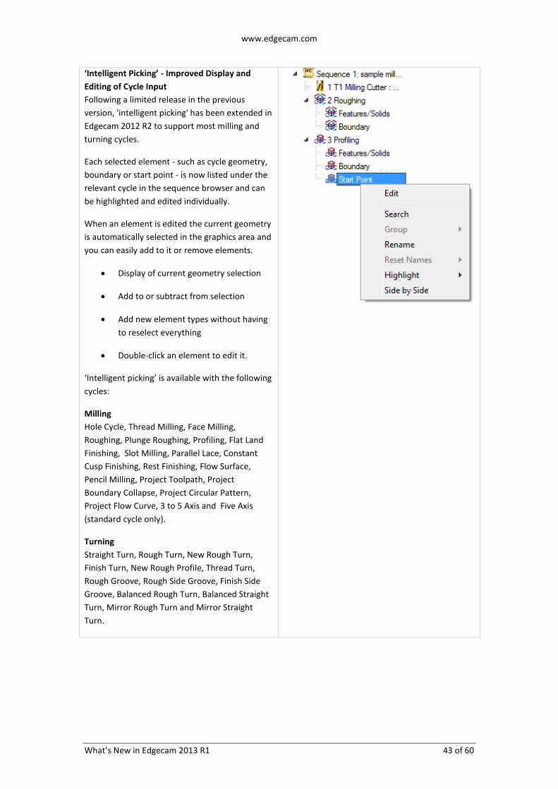
‘Intelligent Picking’ - Improved Display and
Editing of Cycle Input
Following a limited release in the previous
version, 'intelligent picking' has been extended in
Edgecam 2012 R2 to support most milling and
turning cycles.
Each selected element - such as cycle geometry,
boundary or start point - is now listed under the
relevant cycle in the sequence browser and can
be highlighted and edited individually.
When an element is edited the current geometry
is automatically selected in the graphics area and
you can easily add to it or remove elements.
Display of current geometry selection
Add to or subtract from selection
Add new element types without having
to reselect everything
Double-click an element to edit it.
‘Intelligent picking’ is available with the following
cycles:
Milling
Hole Cycle, Thread Milling, Face Milling,
Roughing, Plunge Roughing, Profiling, Flat Land
Finishing, Slot Milling, Parallel Lace, Constant
Cusp Finishing, Rest Finishing, Flow Surface,
Pencil Milling, Project Toolpath, Project
Boundary Collapse, Project Circular Pattern,
Project Flow Curve, 3 to 5 Axis and Five Axis
(standard cycle only).
Turning
Straight Turn, Rough Turn, New Rough Turn,
Finish Turn, New Rough Profile, Thread Turn,
Rough Groove, Rough Side Groove, Finish Side
Groove, Balanced Rough Turn, Balanced Straight
Turn, Mirror Rough Turn and Mirror Straight
Turn.

www.edgecam.com
What’s New in Edgecam 2013 R1 44 of 60
Simplify Stock Output from ‘Update Stock’
Command
When using the Update Stock command the
stock is replaced by an updated version, in the
form of an STL model from Simulator. The STL
models created increase the saved file size of
your parts and can have a detrimental effect on
Edgecam performance and stability.
The new Maximum Stock Size option allows you
to select at which stock size to simplify the
resulting stock.
Simplify the resultant STL stock and
reduce STL file size
Improve performance and system
stability
Ability to machine more complicated
stock
Note
“Very Large” stock can affect Edgecam’s
performance and the Update Stock command
will always simplify stock of this size.

www.edgecam.com
What’s New in Edgecam 2013 R1 45 of 60
Chaining of Solid Edges
Edgecam 2012 R2 has been enhanced to allow
the chaining of edges on a solid model.
Simplified and improved picking of
edges of a solid model
Can be used where edge picking is
required (Geometry, Edge Loop Feature,
etc).
Tangency and 2D options for improved
edge detection during chaining
Allows simple editing and easy removal
of chained edges
Notes
The new functionality is available on all
solid model types and requires the
appropriate Solid module license.
The new 2D Chain button applies to
both wireframe and edge chaining. In
previous releases the 2D Snap button
was used to constrain wireframe
chaining to the 2D plane; this has
changed to allow more flexibility. You
can now chain in 3D to create geometry
snapped to the 2D plane which was
previously not possible.

www.edgecam.com
What’s New in Edgecam 2013 R1 46 of 60
Rotary Machining of Mill Features
Using the new Solids menu ► Rotary Mill
Feature command it is now possible to manually
identify and machine simple rotary features that
are located on a cylinder. The Rotary Mill
features can be machined on Milling and
Mill/Turn machines. Typical simple mill features
that can be detected and machined include:
Helical grooves
Slots
General cavities (pockets, engraving etc)
Bosses (raised areas) on cylinders
If radial slots are found they are visually
represented by a centreline along the length of
the slot located at the bottom of the feature on
the model. Typical feature profiles supported for
machining of simple radial slots:
Notes on machining of rotary mill features
Rotary Mill Features can be machined using the
Roughing, Profiling or Slot cycle. Note that bosses
can only be machined using the Profiling cycle.
To rotary machine mill features, ensure that:
Rotary Mode is selected
The tool has a radial orientation

www.edgecam.com
What’s New in Edgecam 2013 R1 47 of 60
Composite Feature Enhancement
The Solids menu ► Composite Feature
command allows you to group together a
number of features into a single feature. In 2012
R2 this command has been enhanced:
Select which features to include in the
composite
Multiple composite features on same
plane allowed
Roughing is bounded to composite
region - rough regions of the solid
without the need for boundaries
Use different tools for each region
Note
In the example above it is necessary to create
separate composites for each side because the
tooling and cycle requirements for each side are
quite different.
Feature Finding in Manufacture
Feature Finding commands can now be run in
Manufacture Mode. The appropriate commands
can now be executed from the Solids menu and
Toolbar in Manufacture. Note that the Solids
Toolbar is not displayed in Manufacture by
default.

www.edgecam.com
What’s New in Edgecam 2013 R1 48 of 60
Extracting Silhouette Profiles from Geometry
A new Copy from Body/Faces Silhouette option
has been added to the Solids menu ► Geometry
command that allows you to create a silhouette
from a body or selected faces.
Create geometry from edges that “fall
away” or are rounded
Explode extracted geometry and add
offsets to leave material on areas where
further machining is required
Great for leaving allowances on castings
and forgings
Distinguish between Solids and Sheet/Surface
Bodies in Browser
When working in the ‘tree’ view of the Feature
Browser different icons are now displayed for
the sheet and solid body elements in the model,
making it easier to identify each type in
Edgecam.
A ‘filled’ icon denotes a solid body
A ‘crosshatch’ icon denotes a
sheet/surface body

www.edgecam.com
What’s New in Edgecam 2013 R1 49 of 60
Strategy Manager – Planning Board
The Planning Board is a user interface tool
designed for use with machining strategies, and
it is used in conjunction with the Feature
Browser. The Planning Board gives greater
control over the manufacture order and the
application of strategies. It gives graphical
feedback indicating which strategies have been
applied.
Strategies can be applied one at a time,
applied to a marked set or applied to all.
Strategies can be removed from the
Planning Board if they are not required.
Notes
1. Planning Board is available in the
Strategy Manager and Strategy Manager
Run Only licenses and any licenses that
include either of them, i.e. Solid
Machinist for Education.
2. To use the Planning Board strategies
need to conform to a strict documented
structure. Refer to the Strategy
Manager help file for more details.
3. A set of sample strategies configured for
use with Planning Board are installed
with Edgecam. It is recommended that
you use these sample strategies with a
well configured ToolStore and specify a
Toolkit to see the benefits of Planning
Board.
4. Refer to the Edgecam User Guide for
further details on how to apply
strategies using Planning Board.

www.edgecam.com
What’s New in Edgecam 2013 R1 50 of 60
Strategy Manager – Removing Unwanted
Sequence Markers
The Mark Sequence command (introduced in
2012 R1) can leave unwanted markers in your
instruction sequence. Edgecam 2012 R2 offers a
new command to clear any unwanted markers.
Typically this will be used in a strategy
to remove unwanted markers from a
machining sequence.
Remove individual sequence markers by
name or clear all markers.
Note
The Clear Marks command is not present in the
Edgecam user interface as standard; you will
need to add it to a toolbar or menu. The
command is available in the Edit category.
In Strategy Manager, the command needs to be
added directly to the process using the Add Mark
Clear Command option in the shortcut menu of
the Process browser.
Strategy Manager - Setting Tools Modifiers
Based on Selected Tool
When setting tool modifiers it is now possible to
use tool attributes of the selected tool to
calculate and force other toolchange modifier
values.
In this example the Z Gauge modifier is
calculated using the expression
'Tool.FluteLength+Tool.ShankLength'.
Tool.FluteLength and Tool.ShankLength are taken
from the selected tool, so prior to the strategy
committing the toolchange process other
toolchange modifiers can be derived from the
selected tool attributes.

www.edgecam.com
What’s New in Edgecam 2013 R1 51 of 60
Start Simulation from any Instruction
Simulator has been enhanced in Edgecam 2012
R2 so that you can now start the simulation from
any point in the instruction list.
Use the Sequence Browser (now
available in Simulator) to start the
simulation at any point by clicking the
instruction in the list
Rewind to any previous point in
simulation
No need to simulate the whole
sequence each time, pick exactly which
instructions to simulate
Note
This option is only available in Simulate
Machining mode for Standard licenses and
above.
New Stop Options in Simulator
Simulator allows you to specify where to stop the
simulation, by clicking Simulator toolbar ► Stop
Options and selecting the required options.
In Edgecam 2012 R2, Simulator has been
enhanced for more control over where to stop
the simulation:
Several new options, including ‘Stop at
Axis Overtravel’
It is now possible to select multiple Stop
options, for example you might want to
stop at toolchange and at collisions
Note
Some Stop options are only available in Simulate
Machining mode.

www.edgecam.com
What’s New in Edgecam 2013 R1 52 of 60
Report Axis Overtravel in Simulator
In Edgecam 2012 R2, Simulator has been
enhanced to report axis overtravel.
To use axis limit checking, ensure that Options
menu ► Machining tab ► Report Axis
Overtravel is checked.
The Output window shows the number
of axis limit violations
The Warnings window details the axis
and overtravel distance
Simplified STL Model Output
The Export Stock to STL File dialog now offers
simplified STL model output. This is useful as
complex stock may need to be reduced in size for
more efficient processing in Edgecam or a third
party application.
Simplify STL model output for improved
stability and performance
Reduced STL file size
Accept setting recommended by
Edgecam or make your own choice
based on current stock size
‘Large’ stock simplified by default
Note
Edgecam 2012 R2 also introduces simplified
stock output from the Update Stock command.

www.edgecam.com
What’s New in Edgecam 2013 R1 53 of 60
New Part Modeler Loader for Autodesk Inventor
Part Modeler 2012 R2 introduces a new CAD
loader that allows you to load Autodesk Inventor
parts and assemblies (up to and including 2013)
into Part Modeler. The new license is available
for purchase and is called Part Modeler Loader
for Inventor (Product Code ECPMI-L).
Note: Autodesk Inventor or Autodesk Inventor
View must be installed on the same PC as Part
Modeler to enable the loading of files
The new license is available for purchase and is
called Part Modeler Loader for Inventor (Product
Code ECPMI-L).
Part Modeler Loader for Creo Param The Part Modeler Loader for Creo Parametric has been updated to support the loading of Creo Parametric version 2.0 models.
Filling in Features on Third Party Models
The new 3D Construction menu ► Operation ►
Remove Face command allows you to remove
features from a 3rd party solid model (a model
with no history of features in the tree browser).
Benefits of the new functionality include:
Remove features to obtain an
uninterrupted surface for smooth
machining in Edgecam
Easily develop stage drawings for
manufacture (removing features not
related to the manufacturing process).

www.edgecam.com
What’s New in Edgecam 2013 R1 54 of 60
Enhanced Surface Attributes
Following improvements in the last release, the
Surface Finish Attributes dialog has been further
enhanced in Part Modeler 2012 R2.
The Surface Attribute Viewer has been
integrated into the dialog; move
between tabs for visual feedback of face
settings
New Formed Size setting (Surface Finish
drop-down list) denotes the face is
already to size and requires no
machining (i.e. a cast/forged finish or
previously machined face – no stock to
remove)
Use the Machined Faces Viewer to see
which faces are ‘to size’ and which
require machining
Surface Attribute colours are only
displayed when dialog is active to
ensure surface finish colours do not
overwrite user defined colours
Note
The Formed Size setting is not passed to
Edgecam in this release.

www.edgecam.com
What’s New in Edgecam 2013 R1 55 of 60
Rendered Image on Tapped Holes
Following the introduction of rendered threads in
the last release, this has been extended. In Part
Modeler 2012 R2 it is now possible to render
tapped holes on models.
More realistic representation of (blind
and through) tapped holes
Quickly and accurately view where
tapped holes are located on the solid
model
Thread information is carried through to
Edgecam for machining
Note
Only threads that have been created in
Part Modeler will be rendered.
Array (Linear and Circular Array)
procedures are not supported by this
enhancement. The initial tapped hole
will be rendered, the arrayed tapped
holes will contain the thread data but
will not show the rendered tapped hole
image.
To ensure a 'sharper' display of
rendered threads (graphics card
permitting), the System Options ►
Shading tab ► Enable Shaders option is
checked by default. Note that basic
threads will be displayed even if shaders
are not supported by your graphics card.

www.edgecam.com
What’s New in Edgecam 2013 R1 56 of 60
Editing Procedures from Solid Model
Editing procedures has been enhanced in Part
Modeler 2012 R2. You can now edit a procedure
by double-clicking the feature on the model.
Benefits include:
Simple editing - directly from a
feature without having to search
through the browser tree
Quickly see how complex models have
been constructed
Note
This new feature is only available with solid
models that have been created using Part
Modeler.
New Live Job Reports
Edgecam 2012 R2 introduces new Job Reports
that are markedly faster than current job reports
and - as the title suggests - “Live".
Faster database interrogation
Read database from remote machine/
server
No need to install Edgecam on database
PC
View and print reports in PDF/xlsx/rtf
format
Notes
The new Job Reports are a separate
application that you install from your
Edgecam DVD (\Live Job Reports folder).
If the Job Reports database is on a local
machine no additional configuration is
required and you can launch the reports
straightaway. If the database is located
on a remote machine you use the
"Configure" tab to set up database
access first.
Currently the reports are non-
configurable. There are plans to make
the reports configurable in a future
release.

www.edgecam.com
What’s New in Edgecam 2013 R1 57 of 60
PCI-JavaScript - New Browser and Debugging
Tools
The PCI Variables browser has been redesigned
in Edgecam 2012 R2 for improved development
and feedback when writing PCI-JavaScript.
File Open with history drop-down
Play, Step and Stop options
Improved variable layout
Search for a variable
Watch variables
Output window
The PCI Variables tab lists the variables, their
values, and offers additional features such as File
browser, Search, Play/Step/Stop buttons.
The new Watch tab allows you to track JS
variables while the script is running. Enter the
variable name in the Variable column and the
value and type will be updated.
The Output tab allows you to see the processed
PCI commands with the resolved values. Click
Enable Output to view results.

www.edgecam.com
What’s New in Edgecam 2013 R1 58 of 60
Saving PCI Variables with Part File
Edgecam 2012 R2 offers a new function that
allows you to specify which PCI variables are
saved with a part file.
Opening part file sets any saved PCI
variables
Enhanced PCI Variables Browser
indicates which variables are saved with
part
PCI settings are remembered from the
last time PCI was run on that part
Examples
PCI JavaScript
SaveWithPart(["PCD", "HoleDiam",
"NumHoles"]);
Legacy PCI
%savewithpart=PCD,HoleDiam,Numholes
Notes
Loading a part file that has PCI variables
saved with it will overwrite the PCI
variables in the current session.
Inserting a part does not update the PCI
variables from the file.
Read-only variables in the session will
be overwritten with the ones from the
part file that is being loaded.
You have to set read-only variables
before adding them to the SaveWithPart
list.
When saving an aliased variable, the
referenced variable will also be saved
automatically.

www.edgecam.com
What’s New in Edgecam 2013 R1 59 of 60
Code Wizard Enhancements
There have been a large number of Code Wizard
changes in Edgecam 2012 R2, including items
listed on the following page.
For a list of changes, please refer to the What’s
New section in the Code Wizard user guide (see
illustration on the left).
To take advantage of changes and fixes in the
Code Wizard template files
1. Update your code generator documents
(.CGD files) against their latest template
by re-opening the document in Code
Wizard and confirming the prompt to
update it. (You might want to use the
renaming options in the Template
Update dialog to preserve your original
CGDs during the proving stage.)
2. Recompile the code generators.
3. Regenerate and test any machining that
uses the updated code generators. It is
important to check that the update has
not introduced any unwanted changes.
It is advisable to do this routinely for each new
version of Edgecam.
When updating templates that have an extension
file (.cge) the extension file must also be updated
to ensure compatibility.
CAD Support Enhancements
Edgecam supports the latest versions of a wide
range of CAD systems and CAD file formats.
New in Edgecam 2012 R2 is support for
Autodesk Inventor 2013
CreoTM
Parametric 2.0
CATIA V5 R21
SpaceClaim 2012
For more information on supported CAD
systems, please refer to the Installation Guide.

www.edgecam.com
What’s New in Edgecam 2013 R1 60 of 60
ToolStore Server – 64-bit Support and SQL 2008
R2
The ToolStore server setup has been enhanced in
2012 R2 to support 64-bit operating systems and
install SQL 2008 R2.
Support for the latest operating systems
(32 and 64-bit)
Improved reliability
Improved reporting of installation
problems
Note
As part of the update the Edgecam installation
program has been upgraded too. It will identify if
SQL 2005 is already installed and if there is an
ECSQLEXPRESS instance. If so, it will run a repair
of the SQL 2005 instance and then install an
upgrade to SQL 2008 R2. This is necessary as SQL
2005 may be corrupted and cause problems with
the upgrade.
If no SQL instance is found, it will install SQL 2008
R2.
For more information, please refer to the
Installation Guide.