What's New - · PDF fileReinforced Concrete Series (Footing Designer, ... when calculating...
29
What's New 2018 R2
Transcript of What's New - · PDF fileReinforced Concrete Series (Footing Designer, ... when calculating...

What's New
2018 R2


What's New in GRAITEC Advance BIM Designers 2018 R2
3
Table of Contents
ADVANCE BIM DESIGNERS – CONCRETE SERIES .................................................................................... 4
REINFORCED CONCRETE FOOTING DESIGNER ........................................................................................................ 4 Multi-layer soil calculation ............................................................................................................................... 4 Bottom Constructive Reinforcement ............................................................................................................... 5
REINFORCED CONCRETE COLUMN DESIGNER ........................................................................................................ 5 Beams on top located in front/back ................................................................................................................ 5 Enhanced management of starter bars .......................................................................................................... 6
REINFORCED CONCRETE BEAM DESIGNER ............................................................................................................. 7 Precast functionalities implementation ........................................................................................................... 7 Add/edit lifting hooks (Reinforcement tab) ...................................................................................................... 9 Additional drawing settings ........................................................................................................................... 10 Set support conditions .................................................................................................................................. 11 Improved load definition ................................................................................................................................ 12 Display bending and resisting moments on one diagram ............................................................................. 14
GENERAL IMPROVEMENTS ................................................................................................................................... 14 Simplified definition of graphical parameters ................................................................................................ 14 Load combinations acc. Eurocode 0 using equations 6.10a & 6.10b columns ............................................ 15 Enhanced positioning of drawing components ............................................................................................. 15 Edit drawings in the CAD editor column ....................................................................................................... 16 Character Map with symbols for bars annotation ......................................................................................... 16 Rebar shape codes acc. ISO 3766 for Polish localization ............................................................................ 17 New reports for loads and combinations ...................................................................................................... 17 Sheet templates depending on element type ............................................................................................... 18 Progress bar during calculation .................................................................................................................... 18
MISCELLANEOUS IMPROVEMENTS & CORRECTIONS ............................................................................................... 18
ADVANCE BIM DESIGNERS – STEEL SERIES ......................................................................................... 21
ADVANCE BIM DESIGNERS – STEEL CONNECTION DESIGNER ............................................................................... 21 Additional parameters (according to EN 1090) for main elements ............................................................... 21 Enhanced grid results for Clip angle and Gusset connections ..................................................................... 22 Visually improved views for elements exceeding ratios................................................................................ 22 Improved geometrical method of definition for members ............................................................................. 23 Icons on lists for available stiffeners ............................................................................................................. 23 Additional sections of main element for Gusset connections ....................................................................... 23 Recommendations of weld thickness............................................................................................................ 24 Results of welds on stiffeners verifications in MEP reports .......................................................................... 24 Markings for dimensions of failed constructive condition for holes distances .............................................. 24 Simplified reports for Gusset and Clip Angle ................................................................................................ 25 Independent sorting of anchor groups .......................................................................................................... 25 Miscellaneous improvements & corrections ................................................................................................. 26
ADVANCE BIM DESIGNERS – STAIRS AND RAILINGS DESIGNER ............................................................................. 26 Double angles as posts in “Standard Railing” ............................................................................................... 26 Straight cut for posts ..................................................................................................................................... 27 Perpendicular connection for “Wall mounted railing” .................................................................................... 27 Miscellaneous improvements & corrections ................................................................................................. 28

What's New in GRAITEC Advance BIM Designers 2018 R2
4
Advance BIM Designers – Concrete Series Advance BIM Designers 2018 R2 brings many new options and improvements to modules included in the Reinforced Concrete Series (Footing Designer, Beam Designer and Column Designer).
Reinforced Concrete Footing Designer
Multi-layer soil calculation
For the foundation design, two verifications were added for multi-layer soils: multilayered ground failure check soil layer punching check
The new verifications are used when more than one soil layer is located below the footing’s lowermost point.
Note: Availability of these options depends on localization, subsequently they’re available for Eurocode with National Annexes for France, Germany, the Czech Republic, Poland and Italian code NTC2008.
The Ground Failure Check iterates medium soil parameters and does the regular (one layer) check with these values. The new feature checks whether the „one-layer“ ground failure figure reaches the second layer and uses the existing “one-layer” calculation if available, or calculates the medium friction angle of the reached levels.
The ratio of different layers at the figure’s surface is calculated in order to determine a new medium friction angle. The ratio of the different layers at areas of the ground failure figure is calculated, together with the medium cohesion coefficient and the medium soil unit weight. The soil layer punching check is conducted according to the German code DIN 4017 - annex B.
The check must be performed if: More than one soil layer is located below the footing. The first supporting layer has a thickness less than 2 times the footing’s width. The first layer is stiffer than the second layer and has a friction angle higher than 25°. The second layer is weak or pasty, cohesive and saturated.
In the previously revealed cases, it‘s possible for the footing to punch through the first layer. This is checked with a calculation that takes into consideration the ground failure resistance with the punching condition.

What's New in GRAITEC Advance BIM Designers 2018 R2
5
Bottom Constructive Reinforcement A new Bottom Constructive Reinforcement feature for footings was introduced. As the name suggests, it provides bottom constructive reinforcement, in case it does not result from calculation.
Reinforced Concrete Column Designer
Beams on top located in front/back The Top Column Section feature was enriched with new options allowing the definition of a beam separately for each side of the column (including Left, Right, Front, Back).

What's New in GRAITEC Advance BIM Designers 2018 R2
6
Enhanced management of starter bars For improved management of starter bars in columns, two new options were added to the Reinforced Concrete Column Designer 2018 R2 version: Bars cut off at – allows cutting off main bars at the bottom or at the top face of the beam. For main
bars cut off at the bottom face of the beam, the starter bar length is given a length equal to 2 x Anchorage length + height of the beam. If the main bars are to be cut off at the top face of the beam, the starter bar length will have the length equal to 2 x Anchorage length.
Bars length – allows deciding how to determine the length of starter bars. The following options are available: Anchorage length, Lap length or User value.
What's New in GRAITEC Advance BIM Designers 2018 R2
7
Reinforced Concrete Beam Designer
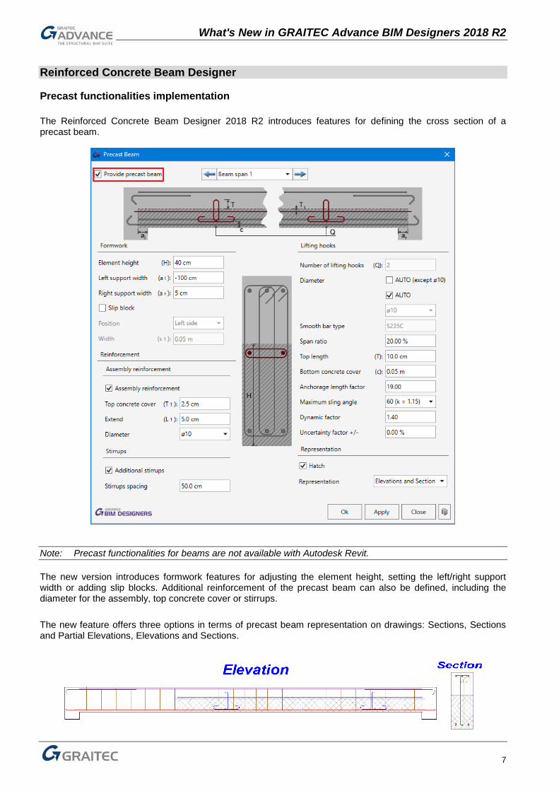
Precast functionalities implementation The Reinforced Concrete Beam Designer 2018 R2 introduces features for defining the cross section of a precast beam.
Note: Precast functionalities for beams are not available with Autodesk Revit.
The new version introduces formwork features for adjusting the element height, setting the left/right support width or adding slip blocks. Additional reinforcement of the precast beam can also be defined, including the diameter for the assembly, top concrete cover or stirrups. The new feature offers three options in terms of precast beam representation on drawings: Sections, Sections and Partial Elevations, Elevations and Sections.

What's New in GRAITEC Advance BIM Designers 2018 R2
8
Lifting hooks Precast beams can now include lifting hooks, which represent special looped bars in the precast beam used for lifting and transporting the beam.
The diameter of the lifting hook, span ratio, top length and bottom concrete cover can be adjusted. The dynamic factor is used for determining the diameter of lifting hooks and takes into account the dynamic effect of lifting the beam. A series of unexpected situations are taken into account, when calculating the uncertainty factor. The Anchorage length factor is considered as a multiple of the bar diameter.
However, the maximum sling angle depends on the top slinging angle (α). The weight of the precast beam (used to calculate the diameter of lifting hooks) will be increased by a certain factor as shown in the following table:
Angle α 0° 15° 22,5° 45° 60°
Slinging coefficient γα 1 1,0086 1,0205 1,08 1,15

What's New in GRAITEC Advance BIM Designers 2018 R2
9
The diameter of lifting hooks is dimensioned considering the effort resulted from the precast beam self-weight (concrete + reinforcement) multiplied by several coefficients. The resulting maximum effort in a lifting hook is calculated by using the formula:
To calculate a required lifting hook diameter, a simple formula is used:
where γw is a weakening hook factor:
Fadm is the admissible force for a lifting hook depending on its diameter presented in the following
table:
Add/edit lifting hooks (Reinforcement tab) Starting with the Reinforced Concrete Beam Designer 2018 R2 version, it is possible to define (or edit previously calculated) lifting hooks by using the dedicated Lifting Hooks tab available in the Results/Reinforcement/Construction joint reinforcement window.
Note: To be able to add lifting hooks manually, the user must first activate the option Provide precast beams available in the Model/Span geometry/Precast beam window.
What's New in GRAITEC Advance BIM Designers 2018 R2
10
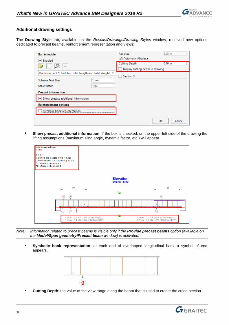
Additional drawing settings The Drawing Style tab, available on the Results/Drawings/Drawing Styles window, received new options dedicated to precast beams, reinforcement representation and views:
Show precast additional information: If the box is checked, on the upper-left side of the drawing the
lifting assumptions (maximum sling angle, dynamic factor, etc.) will appear.
Note: Information related to precast beams is visible only if the Provide precast beams option (available on the Model/Span geometry/Precast beam window) is activated.
Symbolic hook representation: at each end of overlapped longitudinal bars, a symbol of end appears.
Cutting Depth: the value of the view range along the beam that is used to create the cross-section.

What's New in GRAITEC Advance BIM Designers 2018 R2
11
Display cutting depth in drawing: a cutting depth area is shown on the elevation view.
Note: Options related to sections (Cutting Depth and Display cutting depth in drawing) are available for editing separately for each section.
Set support conditions On the group of icons used for setting supports, two new options are added to define Right/Left support conditions.
The highlighted icons open a small window to select a Method and related Value. Available methods include: β1 Mmax : The section at supports should be designed for a bending moment arising from partial fixity
of at least β1 of the maximum bending moment in the span, in accordance with article 9.2.1.2 from EN 1992-1-1
Rotational spring: Defines the support as a rotational spring. If the value for rotational spring is 0, the support is considered an ideal simple support (null bending moment on support).
Degree of restraint: Defines the support degree of restraint as a percentage. The bending moment on support is equal to “x%” from the moment on support when it is fixed.
None: The support has no stiffness and as a result the moment on support will be null (ideal simple support).

What's New in GRAITEC Advance BIM Designers 2018 R2
12
Improved load definition To facilitate the definition of the load on the beam, in the previous version of the Reinforced Concrete Beam Designer module (2018), four tabs of the Load definition window were modified to allow adding loads in tabular mode (Uniform distributed loads, Variable loads, Trapezoidal loads and Punctual loads). In the current latest version (2018 R2) similar changes were made to all other tabs, including: Uniform distributed torsional load
Punctual bending moments
Punctual torsional moments

What's New in GRAITEC Advance BIM Designers 2018 R2
13
Axial loads
Moving loads
All types of loads are defined in the same intuitive way by using tables. The most important options involve assigning a created load to the existing one, adjusting intensity loads and using span, abscissa and length columns to determine the location of a load.
Similar changes are applied to the Internal efforts tab, which is used for the definition / edition of internal loads (coming from the FEM calculations) distributed along the beam’s length.

What's New in GRAITEC Advance BIM Designers 2018 R2
14
Display bending and resisting moments on one diagram A new option Overlap bending and resisting moments is available for diagrams. It allows displaying diagrams of bending moments and resisting moments as overlapped. In addition, another new option Fill area under curves improves appearance by filling areas inside the chart. It is available on Solicitations, Stresses, Reinforcement and Deflection tabs.
General Improvements
Simplified definition of graphical parameters The Display settings dialog, which is opened by an icon available on the Options ribbon, is improved to make it easier to define / change colors of objects displayed in viewports. Colors can be assigned independently for different categories of elements displayed on the model (like reinforcement, dimensions or loads).
Note: The number and type of objects for which the color can be set depends on the module - the Reinforced Concrete Footing Designer module features options for setting the colors for stress distributions, while on the Reinforced Concrete Beam Designer module, colors of loads can also be modified according to the type of force (point / linear).

What's New in GRAITEC Advance BIM Designers 2018 R2
15
Load combinations acc. Eurocode 0 using equations 6.10a & 6.10b columns On the Combination window a new option EC0 Equation is available. It gives the possibility to select one of the methods for defining STR/GEO load combinations according to Eurocode 0: by using an equation 6.10 or equations 6.10a & 6.10b.
According to Eurocode 0 provisions (EC 1990, Annex 1, table A1.2 (B)), the choice of method depends on the National Annex to the standard. Among national annexes implemented in BIM Designers, only the Polish National Annex recommends using equations 6.10a & 6.10b, the selection between the standard method (according to formula 6.10) or the alternative (according to formulas 6.10a & 6.10b) is available only if the Polish NAD or the general Eurocode (no NAD) is set.
Note: A standard method (according to formula 6.10) is used for all National Annexes to Eurocode, other than Polish or General.
Enhanced positioning of drawing components A new tab Coordinates is added to the Drawing settings window, providing the possibility to control the placement of each view in the drawing.
For each view, there are options available to change the X and Y position of the center of the bounding box of the view according to the fixed point (the lower left corner of the drawing). It is possible to set positions by using a page percentage or an offset value.

What's New in GRAITEC Advance BIM Designers 2018 R2
16
Edit drawings in the CAD editor column A new Edit icon is available on the top-left corner of drawings. It opens the associated drawing directly on CAD software (like Advance CAD or AutoCAD) available on the computer. It also gives the option to save a drawing edited on the CAD software and show it in BIM Designers.
Note: The BIM Designer project must be saved before using the Edit option, in order to save changes to the drawing made on the CAD software back to the BIM Designer. Redoing the calculation or regenerating a drawing according to the 3D model causes changes to be overwritten by the newly created drawing.
Character Map with symbols for bars annotation A new selection Character Map is added to the list of available tokens used for annotation of bars on drawings (available on the Bending detail tab of the Drawing settings window). It allows inserting various special symbols.

What's New in GRAITEC Advance BIM Designers 2018 R2
17
Rebar shape codes acc. ISO 3766 for Polish localization A new method is available for Polish localization: Shape code based (ISO 3766). This choice results in rebar shape codes (used in the schedules) and the method of measurement of partial length of bar to be based on the code ISO 3776:2003.
New reports for loads and combinations In addition to the Synthetic, Standard and Detailed reports, that include data and results of calculated elements, a new type of a report is available: Combination Report – Reinforced Concrete Beam Designer 2018 R2 Loads and Combination Report – Reinforced Concrete Footing Designer 2018 R2 Internal Efforts and Combination Report – Reinforced Concrete Column Designer 2018 R2
Depending on the element type (beam, footing or column), new reports include a list of defined combinations (available for all types of elements) and a list of loads (for footings) or a list of internal efforts (for columns).

What's New in GRAITEC Advance BIM Designers 2018 R2
18
Sheet templates depending on element type A new option to select an element type is added to the Drawing Settings dialog, available on the GRAITEC Concrete design/Options/Customize drawing. It allows setting different templates depending on element type, sheet sizes with different title blocks, which can be used for beams, columns, footings and multi-element drawings.
Progress bar during calculation A small window showing the current progress of calculations appears after calculations are launched.
In addition to the informative role, it can also be used for canceling calculations of multiple elements at the same time (in Autodesk Revit).
Miscellaneous improvements & corrections Advance BIM Designers 2018 R2 brings a slew of miscellaneous improvements and corrections.
Improvements: Launch BIM Designers project by double-clicking on a GTCX file;
Generated drawings are saved inside a project file (GTCX), and loaded faster on saved models. Speed improvements to report generator. Import geometry of beams with T sections from Advance Design. Improvement to the mechanism of matching predefined reinforcement bar types from Autodesk Revit
with reinforcement generated by BD modules. Improvement to Autodesk Revit drawing templates for Poland.

What's New in GRAITEC Advance BIM Designers 2018 R2
19
Possibility to use arrows to easily select the active span of the beam.
Improvement to title blocks, default project templates and mapping of parameters for Autodesk Revit
footing families, Germany localization. Dimension lines with eccentricity values on the Eccentricity diagram for footings.
When using the "Copy rebar" option (in Autodesk Revit) the visibility of the copied reinforcement
depends of the source object. Reinforcement visibility option (in Autodesk Revit) with new graphical buttons for the selection of
Rebar appearance.
Introduction of area to element option (in Autodesk Revit) for multiple selection of area reinforcement Additional moments at ends can be disabled (Support conditions option on Spans Management panel)
for US/CAN localization. In Autodesk Revit, parameters for geometric position of elements are featured in the 'Geometric
Position' category.

What's New in GRAITEC Advance BIM Designers 2018 R2
20
• Possibility to change the geometry of multiple beams simultaneously with automatic synchronization across the project in Autodesk Revit.
Note: Tabs Section, Openings and Depressions are grayed, without allowing the user to modify these properties at multiple selection.
Corrections: The bending radius of reinforcement bars is taken into account for drawings of columns (standalone). Improved placement of bar marks to prevent overlapping on other objects on drawings (standalone). Improvement to several problems related to the reports for US/CAN localization (including missing
subparagraphs, issues with miscalculations and displaying some parameters coming from Eurocode).

What's New in GRAITEC Advance BIM Designers 2018 R2
21
Advance BIM Designers – Steel Series
Advance BIM Designers 2018 R2 brings many new features and improvements to the Steel Connection Designer and Stairs and Railings modules.
Advance BIM Designers – Steel Connection Designer
Additional parameters (according to EN 1090) for main elements Two new parameters are available on the Input Assembly window for defining the geometry of connected members: Class of Execution – the class of execution for steel elements, according to EN 1090-2 Family – the family of elements, according to NF EN 1090-2
Note: The Family of elements list is available only for French localization.
The Execution class property is introduced in EN1090-2. This code introduces 4 execution classes (EXC): EXC1, EXC2, EXC3 and EXC4. Each class mandates its own set of requirements, with complexity increasing as the number rises. EXC2 is the most common / default specification. The Family of elements property is introduced in French comment to NF EN1090-2. There are 8 families, marked by letters A, B, C, D, E, D+ and E+. Both parameters are available separately for each member (each linear element, including the main and secondary beam). Although the Execution class parameter is set individually for each connected member, it is automatically assigned to the entire connection, as the min value of the Execution class set for each linear element. The order, starting with the lowest value, is: EXC1, EXC2, EXC3, and EXC4. The Execution class for the entire connection is shown in the Reports and Drawing section.
Class of execution for the entire connection in a report header:
Class of execution for the entire connection on a title block of drawings:

What's New in GRAITEC Advance BIM Designers 2018 R2
22
Enhanced grid results for Clip angle and Gusset connections Clip angle and Gusset connections reports may contain multiple components subjected to verifications. In order to facilitate the design of such connections by quickly identifying joint elements, an 'Object' column was added to the Info Panel for each of these connection types. This column shows information about the item which provided the maximum work ratio for each of the considered verification.
Gusset connection
Clip angle connection
Visually improved views for elements exceeding ratios For any type of connection, if the calculation shows that some connection components (plates, stiffeners, beams, columns, welds) failed verifications (work ratio >100%), then such elements are marked in red, making it easier to identify elements requiring revision and speed up the connection design process.
Note: Only verification results that exceed the 100% work ratio are marked with the color red.

What's New in GRAITEC Advance BIM Designers 2018 R2
23
Improved geometrical method of definition for members Element positioning in the Input Assembly dialog was simplified, offering the possibility to select the reference axis graphically and assign offsets.
Note: The reference axis definition depends on the cross-section of the selected element. Also, the availability of other options, like rotation or offsets, is different for each type of connection and joined element.
Icons on lists for available stiffeners To make it easier to find the corresponding type of stiffener on the list of available items (on the Stiffeners window), as corresponding icons are visible next to each position.
Additional sections of main element for Gusset connections When defining the geometry of the Gusset connection, the cross section of the main element can be set to other than the I-section.

What's New in GRAITEC Advance BIM Designers 2018 R2
24
Recommendations of weld thickness If the weld verification returns a work ratio higher than 100%, the recommended weld thickness is shown as a warning message on the Errors and warnings tab.
Results of welds on stiffeners verifications in MEP reports Results generated by the weld stiffeners verification on the Moment Endplate Connection are available in calculation reports (including full and intermediate reports).
Note: Verification of welds for stiffeners is always performed using the simplified weld design method (as only axial forces are considered for stiffeners).The verification is done only if the column resistance is exceeded.
Markings for dimensions of failed constructive condition for holes distances If some constructive conditions for holes distances fail, then the corresponding dimension lines on the views are displayed in red.

What's New in GRAITEC Advance BIM Designers 2018 R2
25
Simplified reports for Gusset and Clip Angle Simplified reports for Gusset and Clip Angle connections are now available. The one-page simplified report type contains tables summarizing the verification, including basic information about the joint component for which the verification is performed, forces, resistance and status with work ratio for each performed check.
Independent sorting of anchor groups For the Base plate connection, when two or three groups of anchors are enabled (on the Positioning tab of the Anchors window), it is now possible to set horizontal positioning (rows) of anchors for second and third groups separately from the first group. A different number of horizontal anchors for each group can also be set.

What's New in GRAITEC Advance BIM Designers 2018 R2
26
Miscellaneous improvements & corrections Steel Connection Designer 2018 R2 features a number of small improvements and corrections.
Improvements:
Possibility to set the main member position from horizontal to vertical for Gusset joint. On reports of the Clip angle joint, the verifications for identical plates (with the same geometry,
loads, position - in case of a symmetric connection) are displayed only once. Additional dimension lines are added on the views for the Clip Angle connection (including
dimension lines for shortening and copes) and Gusset connection (dimension lines between bolts). Changes in verifications of maximum edge distances for gusset plates (e1, e2) for Gusset joints. Detailed and Intermediate reports for Clip angle and Gusset connections are improved by
introducing better naming of chapters and elements, together with improved explanatory notes at the beginning of each verification for assembly.
On Gusset joint, the effective profile area A of an unequal-leg angle connected by its larger leg is now taken as equal to the gross area (according to EN 1993-1-8, 4.13(2)).
Correction:
Improved geometric inaccuracies, which occur in specific cases when importing the geometry of a joint from Advance Design.
Intermediate reports are now available for Polish localization also for all connection types. Corrected problem with detection of too many collisions between bolts and profiles when parametric
section were used.
Advance BIM Designers – Stairs and Railings Designer
Double angles as posts in “Standard Railing” The selection of compound section of posts now includes angles.

What's New in GRAITEC Advance BIM Designers 2018 R2
27
Straight cut for posts A new option “Aligned to slope” located on the Posts tab under the Posts connection allows the creation of a straight cut for posts on sloped segments.
Perpendicular connection for “Wall mounted railing” A new option “Perpendicular on slope” is now available on the Wall connectors tab under the Connector properties and allows the perpendicular alignment of connectors on sloped segments.

What's New in GRAITEC Advance BIM Designers 2018 R2
28
Miscellaneous improvements & corrections Stairs and Railings Designer 2018 R2 brings several small improvements and corrections:
Improvements: Added reference for hand rail height value and middles rail height and spacing;
Corrections: A collision between elements was corrected for base connection of posts with flat sections; The exact cut between the elements for grab rail end type “Loop” was corrected; Improved behavior of “Use polybeam” option; Improved geometric construction rules for stairs.