What is LiFi? - University of · PDF fileWhat is LiFi? Harald Haas and Cheng Chen The...
3
What is LiFi? Harald Haas and Cheng Chen The University of Edinburgh, King’s Buildings, Edinburgh EH9 3JL, UK, [email protected] Abstract Light-Fidelity (LiFi) takes visible light communication (VLC) further by using light emitting diodes (LEDs) to realise fully networked wireless systems. Synergies are harnessed as lights become LiFi attocells resulting in enhanced wireless capacity for the Internet-of-Things (IoT), 5G and beyond. Introduction Due to the increasing demand for wireless data communication the available radio spectrum be- low 10 GHz (cm-wave communication) has be- come insufficient. The wireless communication industry has responded to this challenge by con- sidering the radio spectrum above 10 GHz (mm- wave communication). However, the higher fre- quencies, f , mean that the path loss, L, in- creases according to Friis free space equation (L ∝ f 2 ). In addition, blockages and shadow- ing in terrestrial communication are more difficult to overcome at higher frequencies. As a con- sequence, the systems must be designed to en- hance the probability of line-of-sight (LoS), typ- ically by using beamforming techniques and by using very small cell sizes (about 50 m). In fact, the need for small cells sizes are not an issue. This is because reducing cells sizes has notably been the major contributor for enhanced system performance in current cellular communications. This means, contrary to the general belief, us- ing higher frequencies for terrestrial communica- tion is a real option. However, the disadvantage is an increased requirement for infrastructure de- ployment. LiFi 6,9 is a natural continuation of the trend to move to higher frequencies in the elec- tromagnetic spectrum. Specifically, LiFi could be classified as nm-wave communication. LiFi uses LEDs for high speed communication, and speeds of over 3 Gbps from a single micro LED 13 have been demonstrated using optimised direct cur- rent optical orthogonal frequency division multi- plexing (DCO-OFDM) modulation 5 . Given that there is a wide-spread deployment of LED light- ing in homes, offices and streetlamps because of their energy-efficiency, there is an added bene- fit for LiFi cellular deployment in that it can build on an existing infrastructure. Moreover, the cell- sizes can be reduced further compared to mm- wave communication leading to the concept of LiFi attocells 10 . LiFi attocells are an additional network layer within the existing heterogeneous Fig. 1: A room of size 20 m × 20 m is considered. The circles in the figure represent the positions of the optical access points (APs), which are also the room lights, while the dots represent the positions of the terminals which can be smartphones or ’things’. Different deployment scenario studied: (a) Hexagonal network model. (b) PPP network model. (c) square network model. (d) HCPP network model. wireless networks, and they have zero interfer- ence from, and add zero interference to, the radio frequency (RF) counterparts such as femtocell networks. A LiFi attocell network uses the lighting system to provide fully networked (multiuser ac- cess and handover) wireless access. This paper provides some initial results of the downlink per- formance of a DCO-OFDM LiFi attocell network and compares the performance to state-of-the-art RF femtocell networks. Modelling LiFi Networks In a LiFi attocell network, the placement of the APs affects the system performance. The light signal from a neighbouring AP causes interfer- ence which limits the signal-to-interference-plus- noise ratio (SINR). Due to the use of LEDs, co- herent transmission is not possible, and data has to be encoded by means of intensity modulation (IM)/direct detection (DD). As a consequence fre- quencies between zero and typically 20 MHz for
Transcript of What is LiFi? - University of · PDF fileWhat is LiFi? Harald Haas and Cheng Chen The...

What is LiFi?
Harald Haas and Cheng Chen
The University of Edinburgh, King’s Buildings, Edinburgh EH9 3JL, UK, [email protected]
Abstract Light-Fidelity (LiFi) takes visible light communication (VLC) further by using light emittingdiodes (LEDs) to realise fully networked wireless systems. Synergies are harnessed as lights becomeLiFi attocells resulting in enhanced wireless capacity for the Internet-of-Things (IoT), 5G and beyond.
Introduction
Due to the increasing demand for wireless datacommunication the available radio spectrum be-low 10 GHz (cm-wave communication) has be-come insufficient. The wireless communicationindustry has responded to this challenge by con-sidering the radio spectrum above 10 GHz (mm-wave communication). However, the higher fre-quencies, f , mean that the path loss, L, in-creases according to Friis free space equation(L ∝ f2). In addition, blockages and shadow-ing in terrestrial communication are more difficultto overcome at higher frequencies. As a con-sequence, the systems must be designed to en-hance the probability of line-of-sight (LoS), typ-ically by using beamforming techniques and byusing very small cell sizes (about 50 m). In fact,the need for small cells sizes are not an issue.This is because reducing cells sizes has notablybeen the major contributor for enhanced systemperformance in current cellular communications.This means, contrary to the general belief, us-ing higher frequencies for terrestrial communica-tion is a real option. However, the disadvantageis an increased requirement for infrastructure de-ployment. LiFi6,9 is a natural continuation of thetrend to move to higher frequencies in the elec-tromagnetic spectrum. Specifically, LiFi could beclassified as nm-wave communication. LiFi usesLEDs for high speed communication, and speedsof over 3 Gbps from a single micro LED13 havebeen demonstrated using optimised direct cur-rent optical orthogonal frequency division multi-plexing (DCO-OFDM) modulation5. Given thatthere is a wide-spread deployment of LED light-ing in homes, offices and streetlamps because oftheir energy-efficiency, there is an added bene-fit for LiFi cellular deployment in that it can buildon an existing infrastructure. Moreover, the cell-sizes can be reduced further compared to mm-wave communication leading to the concept ofLiFi attocells10. LiFi attocells are an additionalnetwork layer within the existing heterogeneous
Fig. 1: A room of size 20 m × 20 m is considered. Thecircles in the figure represent the positions of the optical
access points (APs), which are also the room lights, while thedots represent the positions of the terminals which can be
smartphones or ’things’. Different deployment scenariostudied: (a) Hexagonal network model. (b) PPP network
model. (c) square network model. (d) HCPP network model.
wireless networks, and they have zero interfer-ence from, and add zero interference to, the radiofrequency (RF) counterparts such as femtocellnetworks. A LiFi attocell network uses the lightingsystem to provide fully networked (multiuser ac-cess and handover) wireless access. This paperprovides some initial results of the downlink per-formance of a DCO-OFDM LiFi attocell networkand compares the performance to state-of-the-artRF femtocell networks.
Modelling LiFi NetworksIn a LiFi attocell network, the placement of theAPs affects the system performance. The lightsignal from a neighbouring AP causes interfer-ence which limits the signal-to-interference-plus-noise ratio (SINR). Due to the use of LEDs, co-herent transmission is not possible, and data hasto be encoded by means of intensity modulation(IM)/direct detection (DD). As a consequence fre-quencies between zero and typically 20 MHz for

Tab. 1
Parameters ValuesVertical Separation 2.25 [m]
PD responsivity 0.6 [A/W]PD physical area 1 [cm2]
Receiver field of view 90◦
Receiver noise PSD 10−19 [A2/Hz]
phosphor-coded commercial white LEDs assum-ing a blue filter at the receiver, and between 60MHz – 100 MHz for micro LEDs are used. Thebandwidth can be shared among different opticalAPs according to the well-known frequency reuseconcept7 in order to mitigate co-channel interfer-ence, but this is at the expense of available band-width at each AP. Frequency reuse is modelledwith a parameter ∆. For example, ∆ = 3 meansthat the available modulation bandwidth is dividedinto three equal parts and each part is assignedto an AP in a way that the geometric re-use dis-tance of the same part of the bandwidth is max-imised. Since lighting and wireless data commu-nication are combined the placement of the op-tical APs is mainly determined by the lighting de-sign. The effect of the location of APs is evaluatedfor four different scenarios as shown in Fig. 1.The models developed for cellular RF networksare used because the principal optimisation ob-jectives are similar, namely complete and uniformsignal coverage. Similarly, lighting in home andoffice environments is designed to be able to il-luminate the entire space in a uniform manner8.Fig. 1 a) shows the traditional hexagonal topol-ogy as has been used to analyse RF cellular net-works. Fig. 1 b) shows a random AP deploymentfollowing a Poisson point process (PPP) modelwhich reflects practical cellular network deploy-ments. However, there is a possibility that thedistance between two AP is zero, which is un-realistic. Also, APs can be close to each otherleading to high interference. Frequency re-use of∆ > 1 will reduce interference. Fig. 1 c) shows asquare lattice topology to model a regular light-ing placement used in large offices and publicplaces. Fig. 1 d) shows the Matern type I hard-core point process (HCPP) deployment scenariowhich includes an additional parameter c that con-trols the minimum separation distance betweenany two APs in order to address the limitation ofthe PPP model in Fig. 1 b)12. These four modelsrepresent many specific lighting deployment sce-narios. Experimental validation of this is being un-dertaken. Random user locations are consideredin this work. Fig. 2 shows the cumulative density
function (CDF) of the SINR for the different net-work topologies in Fig. 1. For all scenarios an APdensity of 0.0353 APs/m2 is considered. The op-tical output power of the LiFi AP is set so that theaverage illuminance in the room is at least 500 lxfor reading purposes8. The rest of the system pa-rameters are listed in Tab. 1. From Fig. 2, it canbe seen that the SINR of an APs deployment on ahexagonal lattice gives the best performance, fol-lowed by the deployment on a square lattice. Sim-ilar to the conclusions in1, the SINR performanceof a random PPP network results in worst per-formance. If a minimum distance between APsis enforced by using the HCPP model, the SINRperformance improves as is expected. The re-sults show that the performance of a LiFi opticalattocell network can vary significantly. Assuminga minimum SINR of 3 dB for data transmissionwith acceptable bit error ratio (BER), the probabil-ity that this would be achieved can vary between50 % and 75 %.
The data rate performance is also evaluatedand compared with state-of-the-art RF femtocellnetworks. Optical attocell networks exploit theability of LiFi to achieve a massive spatial reusebecause the typical cell radii, R, are 1 m to 4 menabling a room to have multiple independent LiFiAPs. In contrast, femtocells typically have an or-der of magnitude larger cell radius3. To demon-strate the high data density achieved by an opticalattocell system, the area data rate, sarea, is used,and this is defined as:
sarea =s
Acell, (1)
where Acell is the cell area defined as the cover-age area of a single AP, and s is the throughputof a single cell. The throughput is obtained fromthe SINR using adaptive modulation and codingtables14. The division by the cell area allows fora normalisation for different cell areas, and is re-lated to area spectral efficiency (ASE). Fig. 3shows the area data rate performance of opticalattocell networks and femtocell networks againstchannel bandwidth, as LEDs provide freely avail-able spectrum. Also, Fig. 3 shows the potentialif the future LED devices are improved in termsof their bandwidth. The results of the femtocellnetwork are taken from2–4,11. The indoor ASEachieved by the femtocell network is generally inthe range from 0.03 to 0.0012 bps/Hz/m2. There-fore, this ASE range is used to calculate a mini-mum and maximum area data rate for the bench-mark femtocell network. From Fig. 3 it can be
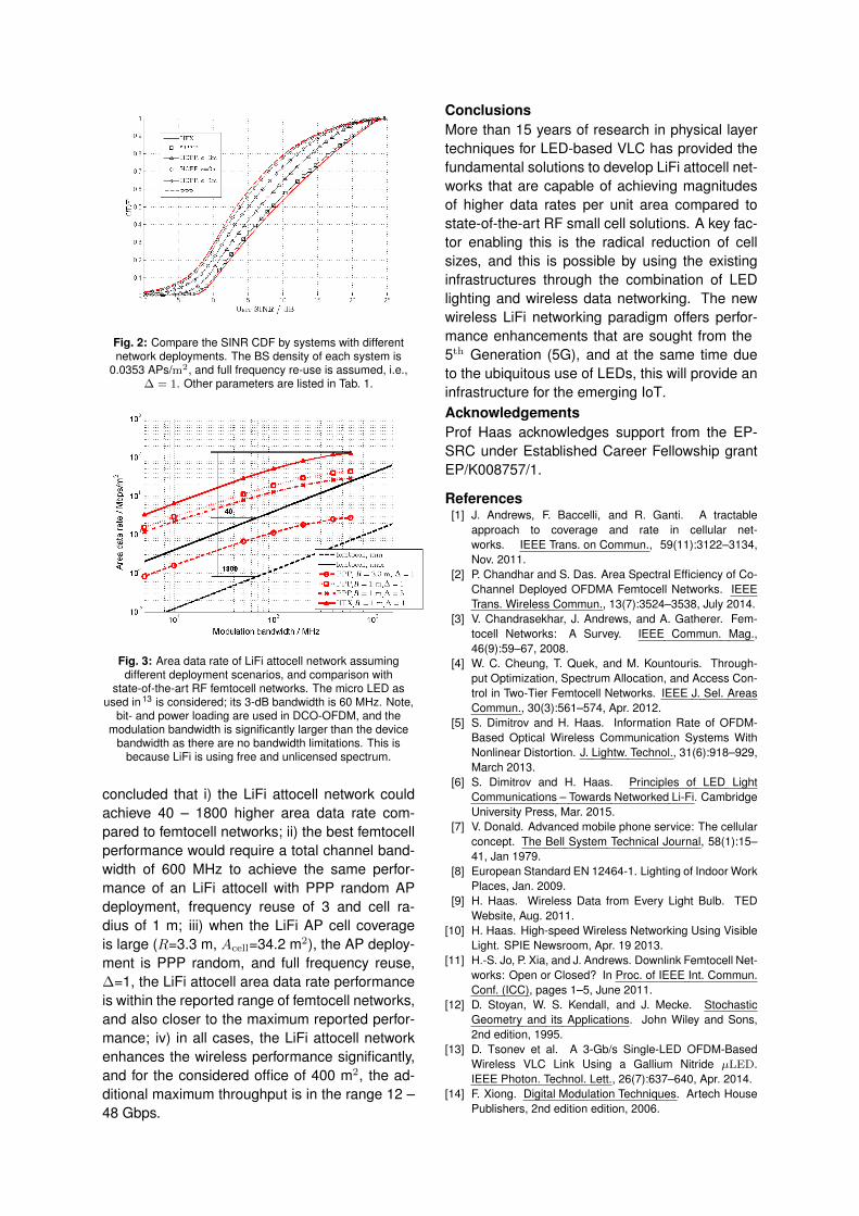
Fig. 2: Compare the SINR CDF by systems with differentnetwork deployments. The BS density of each system is
0.0353 APs/m2, and full frequency re-use is assumed, i.e.,∆ = 1. Other parameters are listed in Tab. 1.
Fig. 3: Area data rate of LiFi attocell network assumingdifferent deployment scenarios, and comparison with
state-of-the-art RF femtocell networks. The micro LED asused in 13 is considered; its 3-dB bandwidth is 60 MHz. Note,
bit- and power loading are used in DCO-OFDM, and themodulation bandwidth is significantly larger than the device
bandwidth as there are no bandwidth limitations. This isbecause LiFi is using free and unlicensed spectrum.
concluded that i) the LiFi attocell network couldachieve 40 – 1800 higher area data rate com-pared to femtocell networks; ii) the best femtocellperformance would require a total channel band-width of 600 MHz to achieve the same perfor-mance of an LiFi attocell with PPP random APdeployment, frequency reuse of 3 and cell ra-dius of 1 m; iii) when the LiFi AP cell coverageis large (R=3.3 m, Acell=34.2 m2), the AP deploy-ment is PPP random, and full frequency reuse,∆=1, the LiFi attocell area data rate performanceis within the reported range of femtocell networks,and also closer to the maximum reported perfor-mance; iv) in all cases, the LiFi attocell networkenhances the wireless performance significantly,and for the considered office of 400 m2, the ad-ditional maximum throughput is in the range 12 –48 Gbps.
ConclusionsMore than 15 years of research in physical layertechniques for LED-based VLC has provided thefundamental solutions to develop LiFi attocell net-works that are capable of achieving magnitudesof higher data rates per unit area compared tostate-of-the-art RF small cell solutions. A key fac-tor enabling this is the radical reduction of cellsizes, and this is possible by using the existinginfrastructures through the combination of LEDlighting and wireless data networking. The newwireless LiFi networking paradigm offers perfor-mance enhancements that are sought from the5th Generation (5G), and at the same time dueto the ubiquitous use of LEDs, this will provide aninfrastructure for the emerging IoT.AcknowledgementsProf Haas acknowledges support from the EP-SRC under Established Career Fellowship grantEP/K008757/1.
References[1] J. Andrews, F. Baccelli, and R. Ganti. A tractable
approach to coverage and rate in cellular net-works. IEEE Trans. on Commun., 59(11):3122–3134,Nov. 2011.
[2] P. Chandhar and S. Das. Area Spectral Efficiency of Co-Channel Deployed OFDMA Femtocell Networks. IEEETrans. Wireless Commun., 13(7):3524–3538, July 2014.
[3] V. Chandrasekhar, J. Andrews, and A. Gatherer. Fem-tocell Networks: A Survey. IEEE Commun. Mag.,46(9):59–67, 2008.
[4] W. C. Cheung, T. Quek, and M. Kountouris. Through-put Optimization, Spectrum Allocation, and Access Con-trol in Two-Tier Femtocell Networks. IEEE J. Sel. AreasCommun., 30(3):561–574, Apr. 2012.
[5] S. Dimitrov and H. Haas. Information Rate of OFDM-Based Optical Wireless Communication Systems WithNonlinear Distortion. J. Lightw. Technol., 31(6):918–929,March 2013.
[6] S. Dimitrov and H. Haas. Principles of LED LightCommunications – Towards Networked Li-Fi. CambridgeUniversity Press, Mar. 2015.
[7] V. Donald. Advanced mobile phone service: The cellularconcept. The Bell System Technical Journal, 58(1):15–41, Jan 1979.
[8] European Standard EN 12464-1. Lighting of Indoor WorkPlaces, Jan. 2009.
[9] H. Haas. Wireless Data from Every Light Bulb. TEDWebsite, Aug. 2011.
[10] H. Haas. High-speed Wireless Networking Using VisibleLight. SPIE Newsroom, Apr. 19 2013.
[11] H.-S. Jo, P. Xia, and J. Andrews. Downlink Femtocell Net-works: Open or Closed? In Proc. of IEEE Int. Commun.Conf. (ICC), pages 1–5, June 2011.
[12] D. Stoyan, W. S. Kendall, and J. Mecke. StochasticGeometry and its Applications. John Wiley and Sons,2nd edition, 1995.
[13] D. Tsonev et al. A 3-Gb/s Single-LED OFDM-BasedWireless VLC Link Using a Gallium Nitride µLED.IEEE Photon. Technol. Lett., 26(7):637–640, Apr. 2014.
[14] F. Xiong. Digital Modulation Techniques. Artech HousePublishers, 2nd edition edition, 2006.